EP4230079A1 - Fermeture - Google Patents
Fermeture Download PDFInfo
- Publication number
- EP4230079A1 EP4230079A1 EP23150854.0A EP23150854A EP4230079A1 EP 4230079 A1 EP4230079 A1 EP 4230079A1 EP 23150854 A EP23150854 A EP 23150854A EP 4230079 A1 EP4230079 A1 EP 4230079A1
- Authority
- EP
- European Patent Office
- Prior art keywords
- connection
- support element
- belt loop
- base
- area
- Prior art date
- Legal status (The legal status is an assumption and is not a legal conclusion. Google has not performed a legal analysis and makes no representation as to the accuracy of the status listed.)
- Pending
Links
- 230000001681 protective effect Effects 0.000 claims description 10
- 239000011324 bead Substances 0.000 claims description 3
- 230000002787 reinforcement Effects 0.000 description 12
- 239000000463 material Substances 0.000 description 5
- 238000010276 construction Methods 0.000 description 4
- 238000001485 positron annihilation lifetime spectroscopy Methods 0.000 description 4
- 238000004519 manufacturing process Methods 0.000 description 2
- 230000003014 reinforcing effect Effects 0.000 description 2
- 239000004753 textile Substances 0.000 description 2
- 239000000969 carrier Substances 0.000 description 1
- 230000001419 dependent effect Effects 0.000 description 1
- 238000011161 development Methods 0.000 description 1
- 230000018109 developmental process Effects 0.000 description 1
- 238000002347 injection Methods 0.000 description 1
- 239000007924 injection Substances 0.000 description 1
- 238000001746 injection moulding Methods 0.000 description 1
- 230000003993 interaction Effects 0.000 description 1
- 238000009958 sewing Methods 0.000 description 1
Images


Classifications
-
- A—HUMAN NECESSITIES
- A44—HABERDASHERY; JEWELLERY
- A44B—BUTTONS, PINS, BUCKLES, SLIDE FASTENERS, OR THE LIKE
- A44B11/00—Buckles; Similar fasteners for interconnecting straps or the like, e.g. for safety belts
- A44B11/25—Buckles; Similar fasteners for interconnecting straps or the like, e.g. for safety belts with two or more separable parts
- A44B11/258—Buckles; Similar fasteners for interconnecting straps or the like, e.g. for safety belts with two or more separable parts fastening by superposing one part on top of the other
- A44B11/2584—Buckles; Similar fasteners for interconnecting straps or the like, e.g. for safety belts with two or more separable parts fastening by superposing one part on top of the other followed by sliding in the main plane of the buckle
-
- A—HUMAN NECESSITIES
- A41—WEARING APPAREL
- A41D—OUTERWEAR; PROTECTIVE GARMENTS; ACCESSORIES
- A41D13/00—Professional, industrial or sporting protective garments, e.g. surgeons' gowns or garments protecting against blows or punches
- A41D13/05—Professional, industrial or sporting protective garments, e.g. surgeons' gowns or garments protecting against blows or punches protecting only a particular body part
- A41D13/055—Protector fastening, e.g. on the human body
- A41D13/0556—Protector fastening, e.g. on the human body with releasable fastening means
- A41D13/0568—Protector fastening, e.g. on the human body with releasable fastening means with straps
-
- A—HUMAN NECESSITIES
- A41—WEARING APPAREL
- A41F—GARMENT FASTENINGS; SUSPENDERS
- A41F1/00—Fastening devices specially adapted for garments
-
- A—HUMAN NECESSITIES
- A44—HABERDASHERY; JEWELLERY
- A44B—BUTTONS, PINS, BUCKLES, SLIDE FASTENERS, OR THE LIKE
- A44B11/00—Buckles; Similar fasteners for interconnecting straps or the like, e.g. for safety belts
- A44B11/006—Attachment of buckle to strap
-
- A—HUMAN NECESSITIES
- A44—HABERDASHERY; JEWELLERY
- A44B—BUTTONS, PINS, BUCKLES, SLIDE FASTENERS, OR THE LIKE
- A44B11/00—Buckles; Similar fasteners for interconnecting straps or the like, e.g. for safety belts
- A44B11/25—Buckles; Similar fasteners for interconnecting straps or the like, e.g. for safety belts with two or more separable parts
- A44B11/2592—Buckles; Similar fasteners for interconnecting straps or the like, e.g. for safety belts with two or more separable parts fastening by sliding in the main plane or a plane parallel to the main plane of the buckle
- A44B11/2596—Buckles; Similar fasteners for interconnecting straps or the like, e.g. for safety belts with two or more separable parts fastening by sliding in the main plane or a plane parallel to the main plane of the buckle the movement being transverse to the longitudinal direction of the strap or chain
-
- A—HUMAN NECESSITIES
- A45—HAND OR TRAVELLING ARTICLES
- A45F—TRAVELLING OR CAMP EQUIPMENT: SACKS OR PACKS CARRIED ON THE BODY
- A45F5/00—Holders or carriers for hand articles; Holders or carriers for use while travelling or camping
- A45F5/02—Fastening articles to the garment
-
- F—MECHANICAL ENGINEERING; LIGHTING; HEATING; WEAPONS; BLASTING
- F41—WEAPONS
- F41H—ARMOUR; ARMOURED TURRETS; ARMOURED OR ARMED VEHICLES; MEANS OF ATTACK OR DEFENCE, e.g. CAMOUFLAGE, IN GENERAL
- F41H5/00—Armour; Armour plates
- F41H5/013—Mounting or securing armour plates
-
- F—MECHANICAL ENGINEERING; LIGHTING; HEATING; WEAPONS; BLASTING
- F41—WEAPONS
- F41C—SMALLARMS, e.g. PISTOLS, RIFLES; ACCESSORIES THEREFOR
- F41C33/00—Means for wearing or carrying smallarms
- F41C33/02—Holsters, i.e. cases for pistols having means for being carried or worn, e.g. at the belt or under the arm
- F41C33/04—Special attachments therefor
- F41C33/046—Webbing, harnesses, belts or straps for wearing holsters
Definitions
- the present invention relates to a clasp for connecting a functional element to a belt loop.
- the clasp for connecting a functional element such.
- the strap loop can be a PALS loop of a MOLLE system, for example.
- the loop of material can also be formed by a layer of textile material into which slits have been introduced.
- Clasps are also already known for connecting functional elements to belt loops, the base element of which has belt receptacles slotted on both sides, into which the belt loop is threaded.
- the belt loop is connected to the belt mounts at the two edge areas of the base element and runs in the central part of the base element on its rear side.
- Various attachments can be attached to the free central part of the base element.
- the present invention includes a clasp for connecting a functional element to a belt loop, with a base element which has a base area and two bar elements and can be pushed under the belt loop in such a way that the base area is arranged below the belt loop and the bar elements encompass the belt loop on both sides , and with a connection element which can be latched to the web elements of the base element arranged on the belt loop.
- connection element has at least one spring arm, at the free end of which a pawl is provided.
- the pawl can preferably be latched with at least one counter-element arranged on a web element of the base element.
- connection element to be easily latched to the base element.
- the spring arm has a starting bevel, at the end of which the pawl is arranged.
- the at least one spring arm can be inserted under at least one holding area of the web elements for connection to the base element.
- the spring arm rests on the belt loop in the connected state.
- the belt loop preferably presses the pawl into the latched position.
- the pawl is preferably released by pressing the spring arm against the belt loop, the elasticity of which allows a certain yielding.
- the belt loop preferably rests at least partially on the bottom area of the base element in an area which is located in the connected position between the pawl and the free end of the spring arm. This prevents accidental release of the spring arm during operation.
- the counter element of the pawl is formed by an end area of the holding area of the web element.
- the spring arm has a recess and/or one or more bead elements. This facilitates operation, in particular operation with gloves, since the point at which the spring arm has to be pressed to release it is marked haptically.
- the at least one spring arm extends between the web elements in the connected state. As a result, it is protected against unintentional loosening by the web elements.
- the holding areas each protrude inwards from the web elements.
- the pawl engages around the counter-element from below.
- the pawl grips from below a front edge of a holding area, under which the spring arm extends in the latched state.
- the connection element has a support element which encompasses the web elements of the base element in the connected state.
- the support element secures the connection element against tensile loads on the base element.
- the support element encompasses the web elements transversely to the longitudinal direction of the belt loop and thus secures them in the longitudinal direction of the belt loop.
- the support element encompasses the end regions of the web elements.
- the end regions of the web elements encompassed by the support element are in the direction of the Floor area are beveled towards the inside.
- the support element is preferably braced with the end regions when it is pulled away from the base element.
- the support element surrounds the web elements in the connected state like a frame on their outer sides.
- the spring arm preferably extends between the web elements.
- the web elements pass through two recesses arranged between the spring arm and the frame-like support element.
- the end areas of the recesses preferably encompass the end areas of the web elements.
- the support element extends between the web elements in the connected state.
- Two spring arms are preferably provided, which extend on both sides of the support element between the support element and the web elements.
- the support element encompasses the end regions of the web elements and has widened regions for this purpose, which encompass the end regions of the web elements with their inner edges.
- the support element and the at least one spring arm extend parallel to one another in a deformation region of the support element and are separated from one another by a preferably slot-shaped cutout, so that the support element and spring arm can be deformed in opposite directions.
- connection area can have a recess through which the belt element can be guided, in particular in the form of an elongated hole.
- connection element and/or support element are designed in the form of a plate.
- connection element and/or support element extends parallel to the bottom area of the base element in the connected state.
- connection element can also be connected directly to the belt loop, in particular by pushing the spring arm under the belt loop.
- the web elements have holding areas which protrude inwards.
- the base element can be configured as has already been described above.
- the present invention also includes a connecting element for a clasp as described above, the connecting element having at least one spring arm and at least one support element, the support element and the at least one spring arm extending parallel to one another in a deformation region of the support element and by a preferred slot-shaped recess are separated from each other.
- attachment element can be configured as already described above.
- the present invention also includes a set consisting of the connection element and a reinforcement element, as described above.
- the present invention also includes an object, in particular a ballistic protective vest, with a clasp as described above.
- the object preferably has a loop on which the clasp is arranged.
- the loop can be a sewn-on belt loop or a loop formed by a textile layer in which slits have been introduced.
- it is a PALS loop, in particular a MOLLE connection system.
- the clasp serves to attach a ballistic element to the ballistic protective vest, in particular to attach a ballistic plate to a shoulder strap loop of the ballistic protective vest.
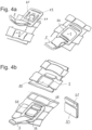
- FIG. 1 to 7 show the function of the clasp, Figures 5 to 7 Construction details.
- the clasp according to the invention serves to connect a functional element to a belt loop 3 of an object 1 that can be worn on the body, for example a protective vest.
- the functional element which is not shown, is connected via a belt element 5, which is fastened to the belt loop 3 by means of the clasp.
- the clasp consists of a base element 10 which, as in 2 shown can be pushed under the belt loop 3, and a connection element 20 which can be connected to the base element 10.
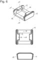
- the base element includes as in 2 and 6 As can be seen, a base area 14 and two bar elements 11 which, when connected to the belt loop 3, extend on both sides of the belt loop in the longitudinal direction of the belt loop, so that the base element encompasses the belt loop on both sides, while the base area 14 under the belt loop 3 passes through the bar elements 11 transverse to the direction of extension of the belt loop 3 connects.
- the base area 14 of the base element is formed by two webs 14 running transversely to the direction in which the belt loop 3 extends, between which webs a recess is provided. This saves material and weight and makes production easier since the injection mold does not have to be as complex.
- the connecting element 20 is connected to the web elements 11 laterally enclosing the belt loop 3 in order to close the clasp and is secured thereto by a latch.
- connection element 20 has a spring arm 21 which, as in 3 shown for attachment to the base element under holding elements 12, which project laterally from the web elements 11, pushed and in the in 1 shown pushed-in position locked.
- a pawl 23 is provided on the spring arm, which latches with counter-elements 13 of the web elements 11 .
- the counter-elements 13 are formed by the end regions of the holding elements 12, under which the spring arm is pushed.
- the pawl locks from below with the lower front edge of the respective holding element 12.
- the two holding elements are each arranged on the inside of the respective web element 11, with the spring arm 21 being pushed under the holding elements 12 between the two web elements. In the pushed-in position, the spring arm 21 therefore rests on the belt loop 3 , which in turn rests on the floor area 14 .
- the locking is released in that the spring arm 21 is pressed into the clasp onto the belt loop, which yields sufficiently due to its elasticity to release the pawl.
- the spring arm 21 has a recess 25 and bead elements 26, which facilitate operation with gloves.
- the recess 25 is arranged in the closed state of the clasp in the area between the two holding elements 12 .
- connection element 20 has one or more connection areas 22 for connection to a belt element 5 .
- the connecting areas 22 are formed by recesses through which a belt loop passes. The edges of the connection element 20 therefore form webs 29 around which the belt loop 5 is placed. The recesses 22 are closed.
- connection area 22 is provided.
- the connection to the belt element 5 is therefore made here in the longitudinal direction of the belt loop 3.
- connection areas can be provided on any sides of the connection element.
- the number of connection areas is also arbitrary and only one connection area can also be provided.
- connection of the belt element 5 is therefore here transverse to the longitudinal direction of the belt loop 3.
- the connection area is formed by a recess 22' and a web 29'.
- connection areas 22 are provided on all four sides of the connection element 20, the connection of the good element 5 can therefore take place in the longitudinal direction and transversely to the longitudinal direction of the belt loop 3.
- connection element is designed in the form of a plate.
- the connection element has a pawl on each of the two main sides, so that it can be connected to the base element regardless of its orientation.
- both main sides are designed identically and/or the connection element has a design that is symmetrical with respect to its central plane.
- the connecting element 20 In order to secure the connecting element 20 to the base element 10, the latter has a carrying element 24 which, in the connected state, encompasses the web elements 11.
- the support element 24 in the embodiment transverse to the extension of the web elements 11 running edges 28 which the end portions 15 of Web elements 11 embrace.
- the support element encompasses the web elements 11 on both longitudinal sides.
- the support element 24 extends parallel to the spring arm 21 in the longitudinal direction of the connection element and connects the edges 28, which encompass the two end regions 15 of the web elements 11, in the longitudinal direction.
- the end regions 15 of the web elements 11 run obliquely inwards, starting from their upper edge towards the bottom region 14 .
- the edges 28 of the support element brace as shown in the corresponding side view in 7 Visible with a tensile load with the end areas 15 and cannot slip off them, since under tensile load the connection element is pressed by the bevels 15 in the direction of the bottom area 14 onto the loop of goods located between the bottom area 14 and the connection element 20 .
- the areas of the support element 24 and the spring arm 21 that extend parallel to one another in the longitudinal direction are separated from one another by a recess 27 so that the two areas can be deformed independently of one another.
- the spring arm 21 can be used as shown in 3 shown are bent downwards out of the plane of the connecting element in order to be pushed under the holding elements 12, while the supporting element is bent upwards in order to push the edges 28 over the web elements 11.
- the edges 28 slide along the upper edges of the bar elements 11 until they enclose the bar elements in their end regions 15 .
- the support element 24 is thinner in the area in which it extends parallel to the spring arm 21 than in its end areas in which the connection areas 22 are provided. This increases flexibility in this area.
- the support element 24 has two arms in the area in which it runs parallel to the spring arm, each of which extends on the outside of the web elements 11 .
- the support element therefore surrounds the web elements in the connected state in the manner of a frame.
- the spring arm extends between the two bar elements 11.
- the bar elements 11 therefore pass through the recess 27 between the spring arm 21 and the arms of the support element 24 in the connected state.
- the edges 28 are formed by the longitudinal ends of this recess 27 .
- the arm of the support element 24 opposite the connection area used for the tensile load is supported on the outside of the associated web element 11 .
- the side walls of the web elements 21 can have an inwardly directed bevel towards the bottom region in order to prevent accidental loosening in the event of a tensile load.
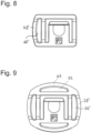
- connection element shown has the same design and mode of operation as that in Figures 1 to 7 described embodiment, so that reference is first made to the description there.
- the support element 44 runs differently than in the other exemplary embodiments in the area between the web elements 11.
- Two spring arms 41 are also provided, which extend on both sides of the centrally running Supporting element 44 extend, with both the spring arms as the support element 44 also run between the web elements 11 .
- the area of the support element 44 in which it extends parallel to the spring arms 41 is separated from the spring arms by slot-shaped recesses 47 .
- This configuration also makes it possible to bend spring arms 41 and support element 44 in opposite directions in order to push the spring arms under holding elements 12 of web elements 11 .
- the area of the support element 44 in which it extends parallel to the spring arms 41 is thinner than the end areas of the support element and the spring arms 41.
- connection areas 42 are provided, which are formed by recesses.
- the closed recesses 42 create a web 49 around which a belt loop can be placed.
- connecting areas 42 are provided on both longitudinal sides of the connecting element.
- the present invention provides an easy-to-use, stable connection of the connection element to the base element, through the interaction of which functional elements can be attached to a belt loop.
- connection element as in Figure 4a shown also be attached directly to the belt loop 3 by the spring arm 21 is pushed behind the belt loop 3 and then runs through the recesses 27 between the spring arm 21 and the support element 24 therethrough.
- Such a connection would also be in the embodiment in Figures 10 and 11 possible by placing the two spring arms behind the Belt loop are pushed, which then runs through the recesses 47. This enables a connection in the transverse direction of the loop.
- a reinforcement element 50 can be used with this type of connection, which reinforces the belt loop 3 so that it cannot deviate when the clasp is loaded.
- the reinforcement element 50 surrounds the belt loop 3 in the assembled state in the form of a sleeve. It has dimensions which allow the support element 24 to surround the reinforcement element 50 in the form of a frame in the assembled state. That area of the belt loop 3 under which the spring arm 21 was pushed is stabilized by the reinforcement element 50 . Furthermore, the reinforcement element rests on the spring arm 21 in the assembled state, so that the edges 28 interlock with the reinforcement element 50 when the connection element is loaded in or against the direction of assembly.
- the reinforcement element 50 has a slot 51 running in the longitudinal direction, by means of which it can be pushed onto the belt loop.
- the reinforcement element 50 is mounted in such a way that the slot 51 is arranged away from the visible surface on the back of the belt loop, the edges of the slot 51 together with the pawl 23 of the spring arm 21 lead to maintaining the safety function by interlocking during disassembly.
- the belt loop 3 can in particular be a PALS loop of a MOLLE fastening system.
- the strap loop 3 can be provided, for example, by sewing a strap 2 onto a carrier layer 1 .
- a strap can be connected to the carrier layer 1 at regular intervals via darts 4 in order to provide several strap loops along the strap 2 .
- the belt loops can also be provided by slots in a material layer, through which belt straps can be threaded in the same way as in an embodiment with the belt straps sewn on as described above.
- the clasp can also be used to connect any other loops.
Applications Claiming Priority (1)
| Application Number | Priority Date | Filing Date | Title |
|---|---|---|---|
| DE102022104175.1A DE102022104175A1 (de) | 2022-02-22 | 2022-02-22 | Schließe |
Publications (1)
| Publication Number | Publication Date |
|---|---|
| EP4230079A1 true EP4230079A1 (fr) | 2023-08-23 |
Family
ID=84901730
Family Applications (1)
| Application Number | Title | Priority Date | Filing Date |
|---|---|---|---|
| EP23150854.0A Pending EP4230079A1 (fr) | 2022-02-22 | 2023-01-10 | Fermeture |
Country Status (4)
| Country | Link |
|---|---|
| US (1) | US20230263272A1 (fr) |
| EP (1) | EP4230079A1 (fr) |
| CA (1) | CA3190133A1 (fr) |
| DE (1) | DE102022104175A1 (fr) |
Citations (8)
| Publication number | Priority date | Publication date | Assignee | Title |
|---|---|---|---|---|
| DE69906020T2 (de) | 1998-12-18 | 2004-02-05 | National Molding Corp. | Mehrzweckbefestigungsvorrichtung |
| US20080061098A1 (en) * | 2006-09-08 | 2008-03-13 | Hoffner Brian D | Harness for firearm accessories |
| WO2009048584A1 (fr) | 2007-10-09 | 2009-04-16 | Gregory Thomas M | Plateforme rotative d'attache d'accessoire |
| US20110061211A1 (en) * | 2009-09-17 | 2011-03-17 | Joseph Anscher | Removable buckle |
| US20120175391A1 (en) | 2007-12-17 | 2012-07-12 | Prezine, Llc | Multi-mount system for removably securing articles to garments |
| US20130181083A1 (en) | 2012-01-16 | 2013-07-18 | Hammerhead Industries, Inc. | Retracting device for mounting to a web strap |
| US20140325803A1 (en) | 2011-12-19 | 2014-11-06 | Illinois Tool Works Inc. | Webbing mounting assembly |
| CA2953176A1 (fr) | 2016-12-28 | 2018-06-28 | Productions Wedoodle Inc. | Pince pivot |
-
2022
- 2022-02-22 DE DE102022104175.1A patent/DE102022104175A1/de active Pending
-
2023
- 2023-01-10 EP EP23150854.0A patent/EP4230079A1/fr active Pending
- 2023-02-06 US US18/165,261 patent/US20230263272A1/en active Pending
- 2023-02-16 CA CA3190133A patent/CA3190133A1/fr active Pending
Patent Citations (8)
| Publication number | Priority date | Publication date | Assignee | Title |
|---|---|---|---|---|
| DE69906020T2 (de) | 1998-12-18 | 2004-02-05 | National Molding Corp. | Mehrzweckbefestigungsvorrichtung |
| US20080061098A1 (en) * | 2006-09-08 | 2008-03-13 | Hoffner Brian D | Harness for firearm accessories |
| WO2009048584A1 (fr) | 2007-10-09 | 2009-04-16 | Gregory Thomas M | Plateforme rotative d'attache d'accessoire |
| US20120175391A1 (en) | 2007-12-17 | 2012-07-12 | Prezine, Llc | Multi-mount system for removably securing articles to garments |
| US20110061211A1 (en) * | 2009-09-17 | 2011-03-17 | Joseph Anscher | Removable buckle |
| US20140325803A1 (en) | 2011-12-19 | 2014-11-06 | Illinois Tool Works Inc. | Webbing mounting assembly |
| US20130181083A1 (en) | 2012-01-16 | 2013-07-18 | Hammerhead Industries, Inc. | Retracting device for mounting to a web strap |
| CA2953176A1 (fr) | 2016-12-28 | 2018-06-28 | Productions Wedoodle Inc. | Pince pivot |
Also Published As
| Publication number | Publication date |
|---|---|
| CA3190133A1 (fr) | 2023-08-22 |
| DE102022104175A1 (de) | 2023-08-24 |
| US20230263272A1 (en) | 2023-08-24 |
Similar Documents
| Publication | Publication Date | Title |
|---|---|---|
| DE19754121B4 (de) | Mehrzweckclip | |
| DE3109792A1 (de) | Schliesse oder schnalle, insbesondere fuer uhrarmbaender | |
| DE8329307U1 (de) | Vorrichtung zum spannen von gurten oder dergleichen | |
| WO2017021312A1 (fr) | Bagage avec dispositif d'arrêt | |
| DE102012000202B4 (de) | Vorrichtung zur Verankerung eines Gurtschlosses und Vorrichtungsanordnung mit wenigstens zwei solchen Vorrichtungen | |
| DE2946229A1 (de) | Reissverschluss | |
| DE3014039A1 (de) | Undurchlaessiges reissverschlussband | |
| EP3490844B1 (fr) | Moyen de sécurité plat | |
| DE102019119267A1 (de) | Schnallenanordnung mit einklemmschutz | |
| EP4230079A1 (fr) | Fermeture | |
| DE102014119575B4 (de) | Tasche mit Tragriemen und Gurtschnalle | |
| DE19829332A1 (de) | Gurthalter | |
| DE3045797A1 (de) | Armband verstellbarer laenge | |
| DE102007041030B4 (de) | Zubehörbefestigung an einem Gepäckträger eines Fahrrades, Adapter und Gepäckträger | |
| EP0922895B1 (fr) | Dispositif à relier un élément allongé | |
| DE4107912A1 (de) | Tragekorb | |
| EP3750744A1 (fr) | Housse de siège pour une partie d'un siège de véhicule automobile | |
| EP0439053B1 (fr) | Fermeture pour ajuster des ceintures de sécurité | |
| DE202007015787U1 (de) | Haltevorrichtung | |
| CH648813A5 (en) | Device for connecting formwork panels stacked one on top of the other | |
| DE102019123573A1 (de) | Transportsicherung | |
| EP0229213A1 (fr) | Chaîne élévatrice à barreaux pour récolteuses de plantes sarclées | |
| DE3805603C2 (fr) | ||
| DE2349795C2 (de) | Innenausstattung für Schutzhelme | |
| DE102021131697A1 (de) | Komponente eines Tragsystems |
Legal Events
| Date | Code | Title | Description |
|---|---|---|---|
| PUAI | Public reference made under article 153(3) epc to a published international application that has entered the european phase |
Free format text: ORIGINAL CODE: 0009012 |
|
| STAA | Information on the status of an ep patent application or granted ep patent |
Free format text: STATUS: THE APPLICATION HAS BEEN PUBLISHED |
|
| AK | Designated contracting states |
Kind code of ref document: A1 Designated state(s): AL AT BE BG CH CY CZ DE DK EE ES FI FR GB GR HR HU IE IS IT LI LT LU LV MC ME MK MT NL NO PL PT RO RS SE SI SK SM TR |
|
| STAA | Information on the status of an ep patent application or granted ep patent |
Free format text: STATUS: REQUEST FOR EXAMINATION WAS MADE |
|
| 17P | Request for examination filed |
Effective date: 20240223 |
|
| RBV | Designated contracting states (corrected) |
Designated state(s): AL AT BE BG CH CY CZ DE DK EE ES FI FR GB GR HR HU IE IS IT LI LT LU LV MC ME MK MT NL NO PL PT RO RS SE SI SK SM TR |