EP4228099B1 - Verbinder - Google Patents
Verbinder Download PDFInfo
- Publication number
- EP4228099B1 EP4228099B1 EP23150085.1A EP23150085A EP4228099B1 EP 4228099 B1 EP4228099 B1 EP 4228099B1 EP 23150085 A EP23150085 A EP 23150085A EP 4228099 B1 EP4228099 B1 EP 4228099B1
- Authority
- EP
- European Patent Office
- Prior art keywords
- contact
- housing
- sheet
- conductive member
- tubular portion
- Prior art date
- Legal status (The legal status is an assumption and is not a legal conclusion. Google has not performed a legal analysis and makes no representation as to the accuracy of the status listed.)
- Active
Links
Images


Classifications
-
- H—ELECTRICITY
- H01—ELECTRIC ELEMENTS
- H01R—ELECTRICALLY-CONDUCTIVE CONNECTIONS; STRUCTURAL ASSOCIATIONS OF A PLURALITY OF MUTUALLY-INSULATED ELECTRICAL CONNECTING ELEMENTS; COUPLING DEVICES; CURRENT COLLECTORS
- H01R13/00—Details of coupling devices of the kinds covered by groups H01R12/70 or H01R24/00 - H01R33/00
- H01R13/02—Contact members
-
- H—ELECTRICITY
- H01—ELECTRIC ELEMENTS
- H01R—ELECTRICALLY-CONDUCTIVE CONNECTIONS; STRUCTURAL ASSOCIATIONS OF A PLURALITY OF MUTUALLY-INSULATED ELECTRICAL CONNECTING ELEMENTS; COUPLING DEVICES; CURRENT COLLECTORS
- H01R12/00—Structural associations of a plurality of mutually-insulated electrical connecting elements, specially adapted for printed circuits, e.g. printed circuit boards [PCB], flat or ribbon cables, or like generally planar structures, e.g. terminal strips, terminal blocks; Coupling devices specially adapted for printed circuits, flat or ribbon cables, or like generally planar structures; Terminals specially adapted for contact with, or insertion into, printed circuits, flat or ribbon cables, or like generally planar structures
- H01R12/50—Fixed connections
- H01R12/59—Fixed connections for flexible printed circuits, flat or ribbon cables or like structures
- H01R12/65—Fixed connections for flexible printed circuits, flat or ribbon cables or like structures characterised by the terminal
-
- H—ELECTRICITY
- H01—ELECTRIC ELEMENTS
- H01R—ELECTRICALLY-CONDUCTIVE CONNECTIONS; STRUCTURAL ASSOCIATIONS OF A PLURALITY OF MUTUALLY-INSULATED ELECTRICAL CONNECTING ELEMENTS; COUPLING DEVICES; CURRENT COLLECTORS
- H01R13/00—Details of coupling devices of the kinds covered by groups H01R12/70 or H01R24/00 - H01R33/00
- H01R13/58—Means for relieving strain on wire connection, e.g. cord grip, for avoiding loosening of connections between wires and terminals within a coupling device terminating a cable
- H01R13/5804—Means for relieving strain on wire connection, e.g. cord grip, for avoiding loosening of connections between wires and terminals within a coupling device terminating a cable comprising a separate cable clamping part
- H01R13/5808—Means for relieving strain on wire connection, e.g. cord grip, for avoiding loosening of connections between wires and terminals within a coupling device terminating a cable comprising a separate cable clamping part formed by a metallic element crimped around the cable
-
- H—ELECTRICITY
- H01—ELECTRIC ELEMENTS
- H01R—ELECTRICALLY-CONDUCTIVE CONNECTIONS; STRUCTURAL ASSOCIATIONS OF A PLURALITY OF MUTUALLY-INSULATED ELECTRICAL CONNECTING ELEMENTS; COUPLING DEVICES; CURRENT COLLECTORS
- H01R12/00—Structural associations of a plurality of mutually-insulated electrical connecting elements, specially adapted for printed circuits, e.g. printed circuit boards [PCB], flat or ribbon cables, or like generally planar structures, e.g. terminal strips, terminal blocks; Coupling devices specially adapted for printed circuits, flat or ribbon cables, or like generally planar structures; Terminals specially adapted for contact with, or insertion into, printed circuits, flat or ribbon cables, or like generally planar structures
- H01R12/70—Coupling devices
- H01R12/77—Coupling devices for flexible printed circuits, flat or ribbon cables or like structures
- H01R12/81—Coupling devices for flexible printed circuits, flat or ribbon cables or like structures connecting to another cable except for flat or ribbon cable
-
- H—ELECTRICITY
- H01—ELECTRIC ELEMENTS
- H01R—ELECTRICALLY-CONDUCTIVE CONNECTIONS; STRUCTURAL ASSOCIATIONS OF A PLURALITY OF MUTUALLY-INSULATED ELECTRICAL CONNECTING ELEMENTS; COUPLING DEVICES; CURRENT COLLECTORS
- H01R13/00—Details of coupling devices of the kinds covered by groups H01R12/70 or H01R24/00 - H01R33/00
- H01R13/40—Securing contact members in or to a base or case; Insulating of contact members
-
- H—ELECTRICITY
- H01—ELECTRIC ELEMENTS
- H01R—ELECTRICALLY-CONDUCTIVE CONNECTIONS; STRUCTURAL ASSOCIATIONS OF A PLURALITY OF MUTUALLY-INSULATED ELECTRICAL CONNECTING ELEMENTS; COUPLING DEVICES; CURRENT COLLECTORS
- H01R13/00—Details of coupling devices of the kinds covered by groups H01R12/70 or H01R24/00 - H01R33/00
- H01R13/46—Bases; Cases
-
- H—ELECTRICITY
- H01—ELECTRIC ELEMENTS
- H01R—ELECTRICALLY-CONDUCTIVE CONNECTIONS; STRUCTURAL ASSOCIATIONS OF A PLURALITY OF MUTUALLY-INSULATED ELECTRICAL CONNECTING ELEMENTS; COUPLING DEVICES; CURRENT COLLECTORS
- H01R9/00—Structural associations of a plurality of mutually-insulated electrical connecting elements, e.g. terminal strips or terminal blocks; Terminals or binding posts mounted upon a base or in a case; Bases therefor
- H01R9/22—Bases, e.g. strip, block, panel
- H01R9/223—Insulating enclosures for terminals
-
- H—ELECTRICITY
- H01—ELECTRIC ELEMENTS
- H01R—ELECTRICALLY-CONDUCTIVE CONNECTIONS; STRUCTURAL ASSOCIATIONS OF A PLURALITY OF MUTUALLY-INSULATED ELECTRICAL CONNECTING ELEMENTS; COUPLING DEVICES; CURRENT COLLECTORS
- H01R2201/00—Connectors or connections adapted for particular applications
- H01R2201/12—Connectors or connections adapted for particular applications for medicine and surgery
-
- H—ELECTRICITY
- H01—ELECTRIC ELEMENTS
- H01R—ELECTRICALLY-CONDUCTIVE CONNECTIONS; STRUCTURAL ASSOCIATIONS OF A PLURALITY OF MUTUALLY-INSULATED ELECTRICAL CONNECTING ELEMENTS; COUPLING DEVICES; CURRENT COLLECTORS
- H01R4/00—Electrically-conductive connections between two or more conductive members in direct contact, i.e. touching one another; Means for effecting or maintaining such contact; Electrically-conductive connections having two or more spaced connecting locations for conductors and using contact members penetrating insulation
- H01R4/10—Electrically-conductive connections between two or more conductive members in direct contact, i.e. touching one another; Means for effecting or maintaining such contact; Electrically-conductive connections having two or more spaced connecting locations for conductors and using contact members penetrating insulation effected solely by twisting, wrapping, bending, crimping, or other permanent deformation
- H01R4/18—Electrically-conductive connections between two or more conductive members in direct contact, i.e. touching one another; Means for effecting or maintaining such contact; Electrically-conductive connections having two or more spaced connecting locations for conductors and using contact members penetrating insulation effected solely by twisting, wrapping, bending, crimping, or other permanent deformation by crimping
- H01R4/183—Electrically-conductive connections between two or more conductive members in direct contact, i.e. touching one another; Means for effecting or maintaining such contact; Electrically-conductive connections having two or more spaced connecting locations for conductors and using contact members penetrating insulation effected solely by twisting, wrapping, bending, crimping, or other permanent deformation by crimping for cylindrical elongated bodies, e.g. cables having circular cross-section
Definitions
- the present invention relates to a connector, particularly to a connector in which a conductive connection object is connected to a flexible conductor of a sheet-like conductive member.
- smart clothes that can obtain user's biological data such as the heart rate and the body temperature only by being worn by the user.
- Such smart clothes are equipped with an electrode disposed at a measurement position and formed of a flexible conductor, and when a wearable device serving as a measurement device is electrically connected to the electrode, it is possible to send biological data to the wearable device.
- Connection between the electrode and the wearable device can be established by using, for example, a connector to be connected to the flexible conductor.
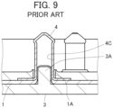
- JP 2018-129244 A discloses a connector shown in FIG. 8 .
- This connector includes a housing 2 and a base member 3 that are separately disposed on opposite sides across a flexible substrate 1 to sandwich the flexible substrate 1.
- a tubular portion 4A of a contact 4 is passed through a contact through-hole 2A of the housing 2, and a flange 4B of the contact 4 is sandwiched between the housing 2 and a flexible conductor 1A exposed on a surface of the flexible substrate 1.
- the housing 2 and the base member 3 are fixed to each other by press-fitting a housing fixing post 3B, which is formed to project on the base member 3, into a post accommodating portion 2B of the housing 2.
- the wearable device When a wearable device is fitted with the connector disclosed in JP 2018-129244 A , the wearable device can be connected to an electrode formed of a flexible conductor.
- connection object such as an electric wire is connected to the contact, whereby the flexible conductor and the connection object are electrically connected to each other.
- the post accommodating portion 2B and the housing fixing post 3B that are for fixing the housing 2 and the base member 3 to each other need to be separately disposed at positions away from the contact 4, and thus it is difficult to reduce a size of the connector.
- US 2020/0025590 A1 describes a connection structure, a touch sensor and a method for forming connection structure.
- US 2020/0235536 A1 describes a coated conductive wire connecting method, a coated conductive wire connecting structure and a coated conductive wire connecting member.
- EP 4 213 308 A1 describes a connector for electrically connecting a connection object to a flexible conductor via a contact.
- the present invention has been made to solve the conventional problem described above and aims at providing a connector capable of reducing the size thereof while a conductive connection object is connected to a flexible conductor of a sheet-like conductive member.
- a connector according to the present invention is one in which a connection object having conductivity is connected to a flexible conductor exposed at least on a bottom surface of a sheet-like conductive member having a top surface and the bottom surface facing in opposite directions from each other, the connector comprising:
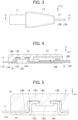
- FIGS. 1 and 2 respectively show perspective views of a connector according to the embodiment when viewed from obliquely upper and lower positions.
- the connector is configured such that a covered electric wire 12 being a conductive connection object is connected to a sheet-like conductive member 11, and includes a housing 13 made of an insulating resin material, and a conductive contact 14 held by the housing 13.
- the sheet-like conductive member 11 has a top surface and a bottom surface facing in opposite directions from each other and has a flexible conductor 11A exposed at least on the bottom surface.
- conductive cloth woven using a conductive thread such as silver can be used, for example.
- the flexible conductor 11A is exposed not only on the bottom surface but also on the top surface of the sheet-like conductive member 11.
- one obtained by applying a conductive ink on a bottom surface of cloth having no conductivity by printing or another method to form the flexible conductor 11A on the bottom surface can also be used as the sheet-like conductive member 11.
- a member obtained by forming the flexible conductor 11A formed of a conductive pattern on a bottom surface of an insulating sheet body such as a resin film may be used as the sheet-like conductive member 11.
- the sheet-like conductive member 11 shown in FIGS. 1 and 2 has a band shape extending in a predetermined direction.
- the covered electric wire 12 has such a structure that an outer periphery of a conductor portion 12A is covered with a covering portion 12B made of an insulating material. With the connector according to the embodiment, the conductor portion 12A of the covered electric wire 12 is electrically connected to the flexible conductor 11A of the sheet-like conductive member 11.
- the covered electric wire 12 shown in FIGS. 1 and 2 extends in the same direction as the direction in which the sheet-like conductive member 11 of band shape extends.
- the housing 13 has a flat plate shape extending in parallel to the sheet-like conductive member 11, and a bottom surface of the housing 13 is provided with a recessed portion 13A of rectangular shape and a linear groove 13B communicating with the recessed portion 13A.
- the sheet-like conductive member 11 and the covered electric wire 12 are connected to each other in the housing 13.
- the contact 14 is accommodated in the recessed portion 13A of the housing 13 and includes a tubular portion 14A of cylindrical shape having a central axis extending in a direction perpendicular to the housing 13 of flat plate shape, and a flange 14B of annular shape joined to the tubular portion 14A.
- a crimp terminal portion 15 integrally formed with the contact 14 is joined to the flange 14B of the contact 14 and accommodated in the groove 13B of the housing 13, and an end portion of the covered electric wire 12 is connected to the crimp terminal portion 15.
- the predetermined direction in which the sheet-like conductive member 11 extends toward the housing 13 is called “+Y direction,” the width direction of the sheet-like conductive member 11 of band shape "X direction,” and the direction orthogonal to an XY plane “Z direction.”
- the sheet-like conductive member 11 and the housing 13 extend along an XY plane.
- the recessed portion 13A is situated on the -Y direction side on a surface, facing in the -Z direction, of the housing 13, and the groove 13B extends in the +Y direction from the recessed portion 13A.
- A+Y directional end portion of the sheet-like conductive member 11 is connected to the contact 14, and a -Y directional end portion of the covered electric wire 12 is connected to the contact 14 via the crimp terminal portion 15.
- the housing 13 has a flat shape apparently formed of a rectangular shape situated on the -Y direction side combined with a trapezoidal shape situated on the +Y direction side when viewed in the Z direction, and has an X directional width that is narrower at its +Y directional end portion than at its -Y directional end portion.
- FIG. 4 that is a cross-sectional view taken along line A-A of FIG. 3 , a bottom surface, facing in the -Z direction, of the recessed portion 13A of the housing 13 forms a first surface P1 facing a +Z directional surface of the sheet-like conductive member 11, and a contact accommodating portion 13C of recess shape recessed in the +Z direction is formed in the first surface P1.
- the housing 13 further includes a projection 13D formed to project in the -Z direction from a bottom surface, facing in the -Z direction, of the contact accommodating portion 13C toward the interior of the contact accommodating portion 13C.
- the tubular potion 14A of the contact 14 is accommodated in the contact accommodating portion 13C.
- the contact 14 includes a top plate portion 14C of annular shape joined to a +Z directional end portion of the tubular portion 14A.
- the top plate portion 14C extends from the +Z directional end portion of the tubular portion 14A toward the central axis of the tubular portion 14A along an XY plane, and faces the bottom surface of the contact accommodating portion 13C.
- a cut-out portion (not shown) is formed near the +Y directional end portion of the sheet-like conductive member 11, and the tubular portion 14A of the contact 14 is accommodated in the contact accommodating portion 13C of the housing 13 while penetrating the cut-out portion of the sheet-like conductive member 11 from the -Z direction with the sheet-like conductive member 11 being sandwiched between the tubular portion 14A and the housing 13. Therefore, the sheet-like conductive member 11 is sandwiched between an inner peripheral surface of the contact accommodating portion 13C of the housing 13 and the tubular portion 14A of the contact 14.
- the flange 14B of annular shape of the contact 14 extends from a -Z directional end portion of the tubular portion 14A to the outside of the tubular portion 14A along an XY plane, and the crimp terminal portion 15 accommodated in the groove 13B of the housing 13 is joined to a +Y directional end portion of the flange 14B.
- the conductor portion 12A at the -Y directional end portion of the covered electric wire 12 is drawn from the covering portion 12B and crimped with the crimp terminal portion 15, and accordingly, the conductor portion 12A of the covered electric wire 12 is electrically connected to the contact 14.
- the top plate portion 14C of the contact 14 is provided with a through hole 14D through which the projection 13D of the housing 13 passes.
- A-Z directional end portion of the projection 13D is provided with a deformed portion 13E extending to the outside of the projection 13D along an XY plane.
- the deformed portion 13E overhangs in a direction along an XY plane in the tubular portion 14A of the contact 14 and covers a surface, facing in the -Z direction, of the top plate portion 14C around the through hole 14D. Consequently, the top plate portion 14C of the contact 14 is pressed in the +Z direction by the deformed portion 13E to thereby be fixed with respect to the housing 13.
- the sheet-like conductive member 11 is bent at a right angle at a position where the tubular portion 14A of the contact 14 is formed, and extends in the +Z direction while being sandwiched between an outer peripheral surface S of the tubular portion 14A and the inner peripheral surface of the contact accommodating portion 13C of the housing 13. Accordingly, the outer peripheral surface S of the tubular portion 14A of the contact 14 comes into contact with the flexible conductor 11A of the sheet-like conductive member 11 in a direction along an XY plane.
- the contact accommodating portion 13C of the housing 13 is formed in advance to have an inside diameter slightly smaller than a dimension obtained by adding a double of a thickness of the sheet-like conductive member 11 to an outside diameter of the tubular portion 14A of the contact 14; therefore, the flexible conductor 11A of the sheet-like conductive member 11 is pressed by the contact accommodating portion 13C against the outer peripheral surface S of the tubular portion 14A of the contact 14 such that a predetermined contact pressure is applied thereto, whereby the contact 14 is electrically connected to the flexible conductor 11A.
- the projection 13D is allowed to project in the -Z direction from the through hole 14D of the top plate portion 14C of the contact 14 as shown in FIGS. 6 and 7 , and thereafter, the deformed portion 13E is formed in the tubular portion 14A of the contact 14 through heat deformation of the -Z directional end portion of the projection 13D, whereby the connector as above can be assembled.
- the conductor portion 12A at the -Y directional end portion of the covered electric wire 12 is drawn from the covering portion 12B and crimped with the crimp terminal portion 15 in advance, and accordingly, the conductor portion 12A of the covered electric wire 12 is electrically connected to the flexible conductor 11A of the sheet-like conductive member 11 via the contact 14 and the crimp terminal portion 15.
- the top plate portion 14C of the contact 14 is fixed with respect to the housing 13 by means of the deformed portion 13E situated at the -Z directional end portion of the projection 13D while the flexible conductor 11A of the sheet-like conductive member 11 and the contact 14 are electrically connected to each other using the contact accommodating portion 13C of the housing 13. Therefore, unlike the connector of JP 2018-129244 A , it is not necessary to dispose a fixing member at a position away from the contact, whereby the connector can be decreased in size.
- the deformed portion 13E that fixes the contact 14 with respect to the housing 13 is disposed inside the tubular portion 14A of the contact 14, particularly, a height size in the Z direction of the connector can be decreased, which makes it possible to obtain a thin connector.
- the connector of the embodiment When the connector of the embodiment is applied to smart clothes, and an electrode (not shown) is connected to the flexible conductor 11A of the sheet-like conductive member 11, the electrode disposed at a measurement position and a wearable device can be connected to each other by means of the inexpensive covered electric wire 12 with low electric resistance.
- the top plate portion 14C of the contact 14 is pressed in the +Z direction by the deformed portion 13E of the housing 13, whereby the flange 14B of the contact 14 can contact, with a predetermined contact pressure, the flexible conductor 11A of the sheet-like conductive member 11 being in contact with the first surface P1 of the housing 13. Therefore, the contact 14 is also electrically connected to the flexible conductor 11A via the flange 14B, whereby the reliability of electric connection between the contact 14 and the flexible conductor 11A can be improved.
- the covered electric wire 12 is connected to the contact 14 by crimping the conductor portion 12A of the covered electric wire 12 to the crimp terminal portion 15, but the invention is not limited thereto, and the covered electric wire 12 can be connected by known various methods such as screw fixing, soldering, welding, and adhesion.
- the covered electric wire 12 is used as a conductive connection object connected to the sheet-like conductive member 11, but an electric wire having only the conductor portion 12A whose outer periphery is not covered with the covering portion 12B made of an insulating material may also be used. Further, various conductors such as a conductor of band shape other than an electric wire can be connected to the contact 14 as a connection object.
Landscapes
- Coupling Device And Connection With Printed Circuit (AREA)
Claims (6)
- Verbinder, bei dem ein Verbindungsobjekt (12), das Leitfähigkeit aufweist, mit einem flexiblen Leiter (11A) verbunden ist, der zumindest auf einer unteren Oberfläche eines flachmaterialartigen leitfähigen Elements (11) freiliegt, das eine obere Oberfläche und die untere Oberfläche aufweist, die in entgegengesetzte Richtungen voneinander weisen, wobei der Verbinder aufweist:einen Kontakt (14) mit Leitfähigkeit, der mit dem Verbindungsobjekt verbunden ist und einen rohrförmigen Abschnitt (14A) und einen oberen Plattenabschnitt (14C) mit ringförmiger Gestalt, der mit einem Ende des rohrförmigen Abschnitts verbunden und mit einem Durchgangsloch (14D) versehen ist, umfasst; undein Gehäuse (13) mit einer ersten Oberfläche (P1), die der oberen Oberfläche des flachmaterialartigen leitfähigen Elements zugewandt ist, und mit einem Kontaktaufnahmeabschnitt (13C) mit einer Aussparungsform, der in der ersten Oberfläche ausgebildet ist und den rohrförmigen Abschnitt des Kontakts aufnimmt,wobei das Gehäuse (13) einen Vorsprung (13D) aufweist, der so ausgebildet ist, dass er von einer Bodenfläche des Kontaktaufnahmeabschnitts in den Kontaktaufnahmeabschnitt hineinragt und das Durchgangsloch des oberen Plattenabschnitts durchdringt, der mit dem rohrförmigen Abschnitt verbunden ist, der in dem Kontaktaufnahmeabschnitt aufgenommen ist,
dadurch gekennzeichnet, dass
ein verformter Abschnitt (13E) in einer Richtung entlang der ersten Fläche von einer Spitze des Vorsprungs in dem rohrförmigen Abschnitt überhängt und den oberen Plattenabschnitt um das Durchgangsloch herum abdeckt, undwobei der obere Plattenabschnitt des Kontakts an dem Gehäuse durch den verformten Abschnitt des Vorsprungs in einem Zustand befestigt ist, in dem die erste Oberfläche des Gehäuses mit der oberen Oberfläche des flachmaterialartigen leitfähigen Elements in Kontakt steht und der rohrförmige Abschnitt des Kontakts in dem Kontaktaufnahmeabschnitt aufgenommen ist, wobei das flachmaterialartige leitfähige Element dazwischen sandwichartig aufgenommen ist, und eine äußere Umfangsfläche des rohrförmigen Abschnitts mit dem flexiblen Leiter des flachmaterialartigen leitfähigen Elements in einer Richtung parallel zu der ersten Oberfläche in Kontakt steht, wodurch das Verbindungsobjekt über den Kontakt elektrisch mit dem flexiblen Leiter verbunden ist. - Verbinder nach Anspruch 1, wobei der Kontaktaufnahmeabschnitt (13C) des Gehäuses einen Innendurchmesser hat, der kleiner ist als eine Abmessung, die man erhält, wenn man das Doppelte einer Dicke des flachmaterialartigen leitfähigen Elements (11) zu einem Außendurchmesser des rohrförmigen Abschnitts (14A) des Kontakts addiert.
- Der Verbinder nach Anspruch 1 oder 2,wobei der Kontakt (14) einen Flansch (14B) aufweist, der mit einem anderen Ende des rohrförmigen Abschnitts verbunden ist und sich in einer Richtung entlang der ersten Oberfläche des Gehäuses erstreckt, undwobei der Flansch mit dem flexiblen Leiter (11A) des flachmaterialartigen leitfähigen Elements in Kontakt steht.
- Der Verbinder nach Anspruch 3, aufweisend einen Crimpanschlussabschnitt (15), der mit dem Flansch (14B) verbunden ist und mit dem Verbindungsobjekt verbunden werden soll.
- Der Verbinder nach einem der Ansprüche 1-4, wobei das Verbindungsobjekt aus einem elektrischen Draht (12) besteht.
- Verbinder nach einem der Ansprüche 1 bis 5, wobei das Gehäuse (13) aus einem isolierenden Harzmaterial hergestellt ist.
Applications Claiming Priority (1)
| Application Number | Priority Date | Filing Date | Title |
|---|---|---|---|
| JP2022020351A JP2023117663A (ja) | 2022-02-14 | 2022-02-14 | コネクタ |
Publications (2)
| Publication Number | Publication Date |
|---|---|
| EP4228099A1 EP4228099A1 (de) | 2023-08-16 |
| EP4228099B1 true EP4228099B1 (de) | 2024-10-16 |
Family
ID=84799955
Family Applications (1)
| Application Number | Title | Priority Date | Filing Date |
|---|---|---|---|
| EP23150085.1A Active EP4228099B1 (de) | 2022-02-14 | 2023-01-03 | Verbinder |
Country Status (4)
| Country | Link |
|---|---|
| US (1) | US20230261415A1 (de) |
| EP (1) | EP4228099B1 (de) |
| JP (1) | JP2023117663A (de) |
| CN (1) | CN116598806A (de) |
Citations (1)
| Publication number | Priority date | Publication date | Assignee | Title |
|---|---|---|---|---|
| EP4213308A1 (de) * | 2022-01-12 | 2023-07-19 | Japan Aviation Electronics Industry, Ltd. | Verbinder |
Family Cites Families (3)
| Publication number | Priority date | Publication date | Assignee | Title |
|---|---|---|---|---|
| JP6718603B2 (ja) * | 2016-10-11 | 2020-07-08 | 株式会社東海理化電機製作所 | 接続構造体及びタッチセンサ |
| JP6840559B2 (ja) | 2017-02-10 | 2021-03-10 | 日本航空電子工業株式会社 | コネクタ |
| JP7216556B2 (ja) * | 2019-01-22 | 2023-02-01 | 日本航空電子工業株式会社 | 被覆導線の接続方法、被覆導線の接続構造および被覆導線の接続部材 |
-
2022
- 2022-02-14 JP JP2022020351A patent/JP2023117663A/ja active Pending
- 2022-12-29 CN CN202211713025.7A patent/CN116598806A/zh active Pending
-
2023
- 2023-01-03 EP EP23150085.1A patent/EP4228099B1/de active Active
- 2023-01-03 US US18/149,626 patent/US20230261415A1/en not_active Abandoned
Patent Citations (1)
| Publication number | Priority date | Publication date | Assignee | Title |
|---|---|---|---|---|
| EP4213308A1 (de) * | 2022-01-12 | 2023-07-19 | Japan Aviation Electronics Industry, Ltd. | Verbinder |
Also Published As
| Publication number | Publication date |
|---|---|
| US20230261415A1 (en) | 2023-08-17 |
| JP2023117663A (ja) | 2023-08-24 |
| EP4228099A1 (de) | 2023-08-16 |
| CN116598806A (zh) | 2023-08-15 |
Similar Documents
| Publication | Publication Date | Title |
|---|---|---|
| EP3435490B1 (de) | Verbindungsunterstützungselement und leiterplattenanordnung | |
| EP4340135B1 (de) | Verbinder | |
| EP4346017B1 (de) | Verbinder | |
| EP4329104A1 (de) | Verbinder | |
| US20230223717A1 (en) | Connector | |
| US12230907B2 (en) | Electrical connector for connecting an electric wire to a flat flexible conductor and an electrical connector assembly therefor | |
| EP4228099B1 (de) | Verbinder | |
| US10862254B2 (en) | Coated conductive wire connecting method, coated conductive wire connecting structure and coated conductive wire connecting member | |
| EP4462605B1 (de) | Verbinder | |
| CN118117364A (zh) | 连接器组装体和连接方法 | |
| EP4336658B1 (de) | Verbinder | |
| JP7822294B2 (ja) | コネクタ、コネクタ組立体および接続方法 | |
| JP7837843B2 (ja) | コネクタ | |
| EP4343974A1 (de) | Verbinder | |
| US20240145955A1 (en) | Connector and connector assembly | |
| JP3415041B2 (ja) | コネクタ | |
| JP2024178974A (ja) | コネクタおよびコネクタ組立体 |
Legal Events
| Date | Code | Title | Description |
|---|---|---|---|
| PUAI | Public reference made under article 153(3) epc to a published international application that has entered the european phase |
Free format text: ORIGINAL CODE: 0009012 |
|
| STAA | Information on the status of an ep patent application or granted ep patent |
Free format text: STATUS: REQUEST FOR EXAMINATION WAS MADE |
|
| 17P | Request for examination filed |
Effective date: 20230103 |
|
| AK | Designated contracting states |
Kind code of ref document: A1 Designated state(s): AL AT BE BG CH CY CZ DE DK EE ES FI FR GB GR HR HU IE IS IT LI LT LU LV MC ME MK MT NL NO PL PT RO RS SE SI SK SM TR |
|
| RBV | Designated contracting states (corrected) |
Designated state(s): AL AT BE BG CH CY CZ DE DK EE ES FI FR GB GR HR HU IE IS IT LI LT LU LV MC ME MK MT NL NO PL PT RO RS SE SI SK SM TR |
|
| STAA | Information on the status of an ep patent application or granted ep patent |
Free format text: STATUS: EXAMINATION IS IN PROGRESS |
|
| 17Q | First examination report despatched |
Effective date: 20231201 |
|
| GRAP | Despatch of communication of intention to grant a patent |
Free format text: ORIGINAL CODE: EPIDOSNIGR1 |
|
| STAA | Information on the status of an ep patent application or granted ep patent |
Free format text: STATUS: GRANT OF PATENT IS INTENDED |
|
| RIC1 | Information provided on ipc code assigned before grant |
Ipc: H01R 4/18 20060101ALN20240503BHEP Ipc: H01R 12/81 20110101ALI20240503BHEP Ipc: H01R 12/65 20110101ALI20240503BHEP Ipc: H01R 9/22 20060101AFI20240503BHEP |
|
| INTG | Intention to grant announced |
Effective date: 20240529 |
|
| GRAS | Grant fee paid |
Free format text: ORIGINAL CODE: EPIDOSNIGR3 |
|
| GRAA | (expected) grant |
Free format text: ORIGINAL CODE: 0009210 |
|
| STAA | Information on the status of an ep patent application or granted ep patent |
Free format text: STATUS: THE PATENT HAS BEEN GRANTED |
|
| AK | Designated contracting states |
Kind code of ref document: B1 Designated state(s): AL AT BE BG CH CY CZ DE DK EE ES FI FR GB GR HR HU IE IS IT LI LT LU LV MC ME MK MT NL NO PL PT RO RS SE SI SK SM TR |
|
| RAP3 | Party data changed (applicant data changed or rights of an application transferred) |
Owner name: JAPAN AVIATION ELECTRONICS INDUSTRY, LIMITED |
|
| REG | Reference to a national code |
Ref country code: GB Ref legal event code: FG4D |
|
| REG | Reference to a national code |
Ref country code: CH Ref legal event code: EP |
|
| REG | Reference to a national code |
Ref country code: IE Ref legal event code: FG4D |
|
| REG | Reference to a national code |
Ref country code: DE Ref legal event code: R096 Ref document number: 602023000706 Country of ref document: DE |
|
| REG | Reference to a national code |
Ref country code: LT Ref legal event code: MG9D |
|
| REG | Reference to a national code |
Ref country code: NL Ref legal event code: MP Effective date: 20241016 |
|
| REG | Reference to a national code |
Ref country code: AT Ref legal event code: MK05 Ref document number: 1733717 Country of ref document: AT Kind code of ref document: T Effective date: 20241016 |
|
| PG25 | Lapsed in a contracting state [announced via postgrant information from national office to epo] |
Ref country code: NL Free format text: LAPSE BECAUSE OF FAILURE TO SUBMIT A TRANSLATION OF THE DESCRIPTION OR TO PAY THE FEE WITHIN THE PRESCRIBED TIME-LIMIT Effective date: 20241016 |
|
| PG25 | Lapsed in a contracting state [announced via postgrant information from national office to epo] |
Ref country code: NL Free format text: LAPSE BECAUSE OF FAILURE TO SUBMIT A TRANSLATION OF THE DESCRIPTION OR TO PAY THE FEE WITHIN THE PRESCRIBED TIME-LIMIT Effective date: 20241016 |
|
| PG25 | Lapsed in a contracting state [announced via postgrant information from national office to epo] |
Ref country code: PT Free format text: LAPSE BECAUSE OF FAILURE TO SUBMIT A TRANSLATION OF THE DESCRIPTION OR TO PAY THE FEE WITHIN THE PRESCRIBED TIME-LIMIT Effective date: 20250217 Ref country code: IS Free format text: LAPSE BECAUSE OF FAILURE TO SUBMIT A TRANSLATION OF THE DESCRIPTION OR TO PAY THE FEE WITHIN THE PRESCRIBED TIME-LIMIT Effective date: 20250216 Ref country code: HR Free format text: LAPSE BECAUSE OF FAILURE TO SUBMIT A TRANSLATION OF THE DESCRIPTION OR TO PAY THE FEE WITHIN THE PRESCRIBED TIME-LIMIT Effective date: 20241016 |
|
| PGFP | Annual fee paid to national office [announced via postgrant information from national office to epo] |
Ref country code: DE Payment date: 20250110 Year of fee payment: 3 |
|
| PG25 | Lapsed in a contracting state [announced via postgrant information from national office to epo] |
Ref country code: FI Free format text: LAPSE BECAUSE OF FAILURE TO SUBMIT A TRANSLATION OF THE DESCRIPTION OR TO PAY THE FEE WITHIN THE PRESCRIBED TIME-LIMIT Effective date: 20241016 |
|
| PG25 | Lapsed in a contracting state [announced via postgrant information from national office to epo] |
Ref country code: BG Free format text: LAPSE BECAUSE OF FAILURE TO SUBMIT A TRANSLATION OF THE DESCRIPTION OR TO PAY THE FEE WITHIN THE PRESCRIBED TIME-LIMIT Effective date: 20241016 |
|
| PG25 | Lapsed in a contracting state [announced via postgrant information from national office to epo] |
Ref country code: ES Free format text: LAPSE BECAUSE OF FAILURE TO SUBMIT A TRANSLATION OF THE DESCRIPTION OR TO PAY THE FEE WITHIN THE PRESCRIBED TIME-LIMIT Effective date: 20241016 |
|
| PG25 | Lapsed in a contracting state [announced via postgrant information from national office to epo] |
Ref country code: NO Free format text: LAPSE BECAUSE OF FAILURE TO SUBMIT A TRANSLATION OF THE DESCRIPTION OR TO PAY THE FEE WITHIN THE PRESCRIBED TIME-LIMIT Effective date: 20250116 |
|
| PG25 | Lapsed in a contracting state [announced via postgrant information from national office to epo] |
Ref country code: LV Free format text: LAPSE BECAUSE OF FAILURE TO SUBMIT A TRANSLATION OF THE DESCRIPTION OR TO PAY THE FEE WITHIN THE PRESCRIBED TIME-LIMIT Effective date: 20241016 Ref country code: AT Free format text: LAPSE BECAUSE OF FAILURE TO SUBMIT A TRANSLATION OF THE DESCRIPTION OR TO PAY THE FEE WITHIN THE PRESCRIBED TIME-LIMIT Effective date: 20241016 Ref country code: GR Free format text: LAPSE BECAUSE OF FAILURE TO SUBMIT A TRANSLATION OF THE DESCRIPTION OR TO PAY THE FEE WITHIN THE PRESCRIBED TIME-LIMIT Effective date: 20250117 |
|
| PG25 | Lapsed in a contracting state [announced via postgrant information from national office to epo] |
Ref country code: PL Free format text: LAPSE BECAUSE OF FAILURE TO SUBMIT A TRANSLATION OF THE DESCRIPTION OR TO PAY THE FEE WITHIN THE PRESCRIBED TIME-LIMIT Effective date: 20241016 |
|
| PG25 | Lapsed in a contracting state [announced via postgrant information from national office to epo] |
Ref country code: RS Free format text: LAPSE BECAUSE OF FAILURE TO SUBMIT A TRANSLATION OF THE DESCRIPTION OR TO PAY THE FEE WITHIN THE PRESCRIBED TIME-LIMIT Effective date: 20250116 |
|
| PG25 | Lapsed in a contracting state [announced via postgrant information from national office to epo] |
Ref country code: SM Free format text: LAPSE BECAUSE OF FAILURE TO SUBMIT A TRANSLATION OF THE DESCRIPTION OR TO PAY THE FEE WITHIN THE PRESCRIBED TIME-LIMIT Effective date: 20241016 |
|
| PG25 | Lapsed in a contracting state [announced via postgrant information from national office to epo] |
Ref country code: DK Free format text: LAPSE BECAUSE OF FAILURE TO SUBMIT A TRANSLATION OF THE DESCRIPTION OR TO PAY THE FEE WITHIN THE PRESCRIBED TIME-LIMIT Effective date: 20241016 |
|
| REG | Reference to a national code |
Ref country code: DE Ref legal event code: R097 Ref document number: 602023000706 Country of ref document: DE |
|
| PG25 | Lapsed in a contracting state [announced via postgrant information from national office to epo] |
Ref country code: EE Free format text: LAPSE BECAUSE OF FAILURE TO SUBMIT A TRANSLATION OF THE DESCRIPTION OR TO PAY THE FEE WITHIN THE PRESCRIBED TIME-LIMIT Effective date: 20241016 |
|
| PG25 | Lapsed in a contracting state [announced via postgrant information from national office to epo] |
Ref country code: RO Free format text: LAPSE BECAUSE OF FAILURE TO SUBMIT A TRANSLATION OF THE DESCRIPTION OR TO PAY THE FEE WITHIN THE PRESCRIBED TIME-LIMIT Effective date: 20241016 |
|
| PG25 | Lapsed in a contracting state [announced via postgrant information from national office to epo] |
Ref country code: SK Free format text: LAPSE BECAUSE OF FAILURE TO SUBMIT A TRANSLATION OF THE DESCRIPTION OR TO PAY THE FEE WITHIN THE PRESCRIBED TIME-LIMIT Effective date: 20241016 |
|
| PG25 | Lapsed in a contracting state [announced via postgrant information from national office to epo] |
Ref country code: CZ Free format text: LAPSE BECAUSE OF FAILURE TO SUBMIT A TRANSLATION OF THE DESCRIPTION OR TO PAY THE FEE WITHIN THE PRESCRIBED TIME-LIMIT Effective date: 20241016 |
|
| PG25 | Lapsed in a contracting state [announced via postgrant information from national office to epo] |
Ref country code: IT Free format text: LAPSE BECAUSE OF FAILURE TO SUBMIT A TRANSLATION OF THE DESCRIPTION OR TO PAY THE FEE WITHIN THE PRESCRIBED TIME-LIMIT Effective date: 20241016 |
|
| PLBE | No opposition filed within time limit |
Free format text: ORIGINAL CODE: 0009261 |
|
| STAA | Information on the status of an ep patent application or granted ep patent |
Free format text: STATUS: NO OPPOSITION FILED WITHIN TIME LIMIT |
|
| PG25 | Lapsed in a contracting state [announced via postgrant information from national office to epo] |
Ref country code: SE Free format text: LAPSE BECAUSE OF FAILURE TO SUBMIT A TRANSLATION OF THE DESCRIPTION OR TO PAY THE FEE WITHIN THE PRESCRIBED TIME-LIMIT Effective date: 20241016 |
|
| PG25 | Lapsed in a contracting state [announced via postgrant information from national office to epo] |
Ref country code: MC Free format text: LAPSE BECAUSE OF FAILURE TO SUBMIT A TRANSLATION OF THE DESCRIPTION OR TO PAY THE FEE WITHIN THE PRESCRIBED TIME-LIMIT Effective date: 20241016 Ref country code: LU Free format text: LAPSE BECAUSE OF NON-PAYMENT OF DUE FEES Effective date: 20250103 |
|
| 26N | No opposition filed |
Effective date: 20250717 |
|
| PG25 | Lapsed in a contracting state [announced via postgrant information from national office to epo] |
Ref country code: BE Free format text: LAPSE BECAUSE OF NON-PAYMENT OF DUE FEES Effective date: 20250131 |
|
| PG25 | Lapsed in a contracting state [announced via postgrant information from national office to epo] |
Ref country code: FR Free format text: LAPSE BECAUSE OF NON-PAYMENT OF DUE FEES Effective date: 20250131 |
|
| REG | Reference to a national code |
Ref country code: BE Ref legal event code: MM Effective date: 20250131 |
|
| PG25 | Lapsed in a contracting state [announced via postgrant information from national office to epo] |
Ref country code: IE Free format text: LAPSE BECAUSE OF NON-PAYMENT OF DUE FEES Effective date: 20250103 |