EP4227594A1 - Air conditioner - Google Patents
Air conditioner Download PDFInfo
- Publication number
- EP4227594A1 EP4227594A1 EP21877223.4A EP21877223A EP4227594A1 EP 4227594 A1 EP4227594 A1 EP 4227594A1 EP 21877223 A EP21877223 A EP 21877223A EP 4227594 A1 EP4227594 A1 EP 4227594A1
- Authority
- EP
- European Patent Office
- Prior art keywords
- heater
- absorbent
- outdoor
- flow channel
- air
- Prior art date
- Legal status (The legal status is an assumption and is not a legal conclusion. Google has not performed a legal analysis and makes no representation as to the accuracy of the status listed.)
- Granted
Links
Images







Classifications
-
- F—MECHANICAL ENGINEERING; LIGHTING; HEATING; WEAPONS; BLASTING
- F24—HEATING; RANGES; VENTILATING
- F24F—AIR-CONDITIONING; AIR-HUMIDIFICATION; VENTILATION; USE OF AIR CURRENTS FOR SCREENING
- F24F1/00—Room units for air-conditioning, e.g. separate or self-contained units or units receiving primary air from a central station
- F24F1/0007—Indoor units, e.g. fan coil units
- F24F1/0087—Indoor units, e.g. fan coil units with humidification means
-
- B—PERFORMING OPERATIONS; TRANSPORTING
- B01—PHYSICAL OR CHEMICAL PROCESSES OR APPARATUS IN GENERAL
- B01D—SEPARATION
- B01D53/00—Separation of gases or vapours; Recovering vapours of volatile solvents from gases; Chemical or biological purification of waste gases, e.g. engine exhaust gases, smoke, fumes, flue gases, aerosols
- B01D53/26—Drying gases or vapours
- B01D53/261—Drying gases or vapours by adsorption
-
- F—MECHANICAL ENGINEERING; LIGHTING; HEATING; WEAPONS; BLASTING
- F24—HEATING; RANGES; VENTILATING
- F24F—AIR-CONDITIONING; AIR-HUMIDIFICATION; VENTILATION; USE OF AIR CURRENTS FOR SCREENING
- F24F1/00—Room units for air-conditioning, e.g. separate or self-contained units or units receiving primary air from a central station
- F24F1/0007—Indoor units, e.g. fan coil units
- F24F1/0035—Indoor units, e.g. fan coil units characterised by introduction of outside air to the room
-
- F—MECHANICAL ENGINEERING; LIGHTING; HEATING; WEAPONS; BLASTING
- F24—HEATING; RANGES; VENTILATING
- F24F—AIR-CONDITIONING; AIR-HUMIDIFICATION; VENTILATION; USE OF AIR CURRENTS FOR SCREENING
- F24F1/00—Room units for air-conditioning, e.g. separate or self-contained units or units receiving primary air from a central station
- F24F1/02—Self-contained room units for air-conditioning, i.e. with all apparatus for treatment installed in a common casing
- F24F1/037—Self-contained room units for air-conditioning, i.e. with all apparatus for treatment installed in a common casing with humidification means
-
- F—MECHANICAL ENGINEERING; LIGHTING; HEATING; WEAPONS; BLASTING
- F24—HEATING; RANGES; VENTILATING
- F24F—AIR-CONDITIONING; AIR-HUMIDIFICATION; VENTILATION; USE OF AIR CURRENTS FOR SCREENING
- F24F11/00—Control or safety arrangements
- F24F11/0008—Control or safety arrangements for air-humidification
-
- F—MECHANICAL ENGINEERING; LIGHTING; HEATING; WEAPONS; BLASTING
- F24—HEATING; RANGES; VENTILATING
- F24F—AIR-CONDITIONING; AIR-HUMIDIFICATION; VENTILATION; USE OF AIR CURRENTS FOR SCREENING
- F24F11/00—Control or safety arrangements
- F24F11/70—Control systems characterised by their outputs; Constructional details thereof
- F24F11/80—Control systems characterised by their outputs; Constructional details thereof for controlling the temperature of the supplied air
- F24F11/87—Control systems characterised by their outputs; Constructional details thereof for controlling the temperature of the supplied air by controlling absorption or discharge of heat in outdoor units
- F24F11/871—Control systems characterised by their outputs; Constructional details thereof for controlling the temperature of the supplied air by controlling absorption or discharge of heat in outdoor units by controlling outdoor fans
-
- F—MECHANICAL ENGINEERING; LIGHTING; HEATING; WEAPONS; BLASTING
- F24—HEATING; RANGES; VENTILATING
- F24F—AIR-CONDITIONING; AIR-HUMIDIFICATION; VENTILATION; USE OF AIR CURRENTS FOR SCREENING
- F24F6/00—Air-humidification, e.g. cooling by humidification
- F24F6/02—Air-humidification, e.g. cooling by humidification by evaporation of water in the air
- F24F6/08—Air-humidification, e.g. cooling by humidification by evaporation of water in the air using heated wet elements
-
- B—PERFORMING OPERATIONS; TRANSPORTING
- B01—PHYSICAL OR CHEMICAL PROCESSES OR APPARATUS IN GENERAL
- B01D—SEPARATION
- B01D2259/00—Type of treatment
- B01D2259/45—Gas separation or purification devices adapted for specific applications
- B01D2259/4508—Gas separation or purification devices adapted for specific applications for cleaning air in buildings
Definitions
- the present disclosure relates to an air conditioner.
- an air conditioner including an indoor unit disposed inside a room to be air-conditioned, and an outdoor unit disposed outside the room.
- the air conditioner is configured to be able to supply humidified outdoor air from the outdoor unit to the indoor unit.
- the air conditioner is sometimes required to perform a humidification operation of supplying humidified outdoor air into a room immediately after starting an air conditioning operation.
- the air conditioner described in PTL 1 there is a possibility that indoor humidification cannot be performed sufficiently and quickly due to a shortage of moisture retained by an adsorbent.
- an object of the present disclosure is to provide an air conditioner capable of sufficiently and quickly performing indoor humidification immediately after starting an air conditioning operation.
- An air conditioner is an air conditioner including an indoor unit and an outdoor unit, the air conditioner including an absorbent, a first flow channel, a second flow channel, a first fan, a second fan, and a heater.
- the absorbent absorbs moisture of outdoor air.
- the first flow channel passes through the absorbent to connect an outdoor space and an inside of the indoor unit, and allows the outdoor air to flow.
- the second flow channel passes through the absorbent, and allows the outdoor air to flow from the outdoor space to the outdoor space.
- the first fan generates a flow of the outdoor air toward the indoor unit in the first flow channel.
- the second fan generates a flow of the outdoor air in the second flow channel.
- the heater heats the outdoor air on an upstream side relative to the absorbent in the first flow channel.
- the air conditioner according to the present disclosure is configured to be able to perform a humidification operation with the heater heating the outdoor air, and the heated outdoor air taking the moisture from the absorbent and flowing toward the indoor unit. After the air conditioner according to the present disclosure stops an air conditioning operation, the second fan operates for a predetermined time to cause the absorbent to retain the moisture.
- the air conditioner according to the present disclosure can sufficiently and quickly perform the indoor humidification immediately after starting the air conditioning operation.
- An air conditioner is an air conditioner including an indoor unit and an outdoor unit, the air conditioner including an absorbent, a first flow channel, a second flow channel, a first fan, a second fan, and a heater.
- the absorbent absorbs moisture of outdoor air.
- the first flow channel passes through the absorbent to connect an outdoor space and an inside of the indoor unit, and allows the outdoor air to flow.
- the second flow channel passes through the absorbent, and allows the outdoor air to flow from the outdoor space to the outdoor space.
- the first fan generates a flow of the outdoor air toward the indoor unit in the first flow channel.
- the second fan generates a flow of the outdoor air in the second flow channel.
- the heater heats the outdoor air on an upstream side relative to the absorbent in the first flow channel.
- the air conditioner according to the present disclosure is configured to be able to perform a humidification operation with the heater heating the outdoor air, and the heated outdoor air taking the moisture from the absorbent and flowing toward the indoor unit. After the air conditioner according to the present disclosure stops an air conditioning operation, the second fan operates for a predetermined time to cause the absorbent to retain the moisture.
- the air conditioner according to the present disclosure can sufficiently and quickly perform the indoor humidification immediately after starting the air conditioning operation.
- the absorbent may be a polymeric sorbent.
- the air conditioner according to the present disclosure may further include a controller that enables a user to set a time to start the air conditioning operation, and the second fan may start to operate before the time to start the air conditioning operation.
- the heater may be a positive temperature coefficient (PTC) heater.
- PTC positive temperature coefficient
- the first flow channel may include a labyrinth that allows the outdoor air to pass.
- a Z-axis direction (vertical direction) in each drawing may be described as an upper/lower direction.
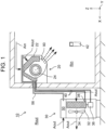
- Fig. 1 is a schematic configuration diagram of air conditioner 10.
- air conditioner 10 includes indoor unit 20 that is disposed in indoor space Rin to be air-conditioned, and outdoor unit 30 that is disposed in outdoor space Rout.
- Indoor unit 20 is provided with heat exchanger 22 and fan 24.
- Heat exchanger 22 performs heat exchange with indoor air Ain of indoor space Rin.
- Fan 24 draws indoor air Ain into indoor unit 20 and blows the air heat-exchanged with heat exchanger 22 into indoor space Rin.
- Outdoor unit 30 is provided with heat exchanger 32, fan 34, compressor 36, and expansion valve 38.
- Heat exchanger 32 performs heat exchange with outdoor air Aout of outdoor space Rout.
- Fan 34 generates a flow of outdoor air Aout passing through heat exchanger 32.
- Heat exchanger 22 of indoor unit 20 and heat exchanger 32, compressor 36, and expansion valve 38 of outdoor unit 30 are connected by refrigerant pipe 40 to constitute a refrigeration cycle of air conditioner 10.
- air conditioner 10 performs a heating operation of blowing heated indoor air Ain into indoor space Rin, a cooling operation of blowing cooled indoor air Ain into indoor space Rin, and a dehumidification operation of blowing dehumidified indoor air Ain into indoor space Rin.
- air conditioner 10 includes controller 42 that enables a user to select the operation of air conditioner 10 such as the heating operation, the cooling operation, and the dehumidification operation, and to set parameters and the like necessary for the operation, such as temperature setting.
- outdoor unit 30 of air conditioner 10 includes ventilation device 50 that supplies outdoor air Aout into indoor space Rin, that is, ventilates indoor space Rin.
- ventilation device 50 does not have to be included in outdoor unit 30.
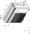
- Fig. 2 is a perspective view illustrating an outer appearance of outdoor unit 30.
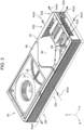
- Fig. 3 is a perspective view illustrating an internal configuration of ventilation device 50.
- Figs. 4 and 5 are a perspective view and a top view of ventilation device 50 from which some of its components are removed.
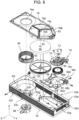
- Fig. 6 is an exploded perspective view of ventilation device 50.
- Fig. 7 is an exploded perspective view of some components of ventilation device 50 as viewed from a different viewpoint.
- Fig. 8 is a schematic sectional view of ventilation device 50.
- ventilation device 50 has housing 52 with an open top, and top panel 54 that is a lid of housing 52.
- Housing 52 of ventilation device 50 includes a plurality of intake ports 52a, 52b, 52c, and exhaust ports 52d, 52e, 52f.
- Intake ports 52a, 52b, 52c are used for drawing outdoor air Aout into housing 52.
- Exhaust ports 52d, 52e, 52f are used for discharging outdoor air Aout drawn into housing 52 to the outside.
- Ventilation conduit 56 illustrated in Fig. 2 is connected to exhaust port 52d. As illustrated in Fig.
- ventilation conduit 56 is attached to a side surface of outdoor unit 30 and is coupled to a ventilation hose that communicates with indoor unit 20. That is, ventilation conduit 56 connects the inside of outdoor unit 30 and the inside of indoor unit 20. Remaining exhaust ports 52e, 52f communicate with outdoor space Rout.
- ventilation device 50 includes absorbent 58 that absorbs moisture of outdoor air Aout, at the center in housing 52.
- Absorbent 58 is a member through which air can pass, and is a member that collects moisture from the passing air or gives moisture to the passing air.
- absorbent 58 is a disk-shaped member that enables the air passage in the vertical direction (Z-axis direction) and that rotates about rotation center line C1 extending in the vertical direction.
- absorbent motor 64 includes gear 62 that meshes with external teeth of holder 60.
- absorbent 58 is preferably formed of a polymeric sorbent that sorbs moisture in the air.
- the polymeric sorbent is composed of, for example, crosslinked sodium polyacrylate.
- the polymeric sorbent has a higher rate of absorbing moisture, can desorb the moisture retained therein at a lower heating temperature, and can retain the moisture for a longer time, than an adsorbent such as silica gel or zeolite can.
- ventilation device 50 also includes first fan 66 that draws outdoor air Aout into ventilation device 50, causes outdoor air Aout to pass through absorbent 58, and blows outdoor air Aout having passed through absorbent 58 toward indoor unit 20.
- First fan 66 is disposed on one side in a longitudinal direction (Y-axis direction) of ventilation device 50 relative to absorbent 58.
- First fan 66 is, for example, a sirocco fan.
- First fan 66 is accommodated in cylindrical part 68a that is provided in partition wall plate 68.
- Partition wall plate 68 divides a space on one side in the longitudinal direction relative to absorbent 58 into upper and lower spaces. As illustrated in Fig. 8 , partition wall plate 68 forms upper space S 1 in contact with a portion of upper surface 58a of absorbent 58, and lower space S2 in contact with a portion of lower surface 58b of absorbent 58.
- Opening 68b connected to exhaust port 52d and opening 68c connected to exhaust port 52e are formed in cylindrical part 68a of partition wall plate 68.
- Through hole 68d for drawing air into first fan 66 in cylindrical part 68a is also formed in partition wall plate 68.
- fan cover 70 that covers first fan 66 is attached to cylindrical part 68a of partition wall plate 68.
- Fan cover 70 is provided with motor 72 that rotates first fan 66.
- fan cover 70 is also provided with damper device 74 that closes one of opening 68b and opening 68c of partition wall plate 68.
- Damper device 74 includes turnable damper 74a, and is configured to close one of opening 68b and opening 68c of partition wall plate 68 by turning damper 74a.
- outdoor air Aout flows into housing 52 through intake ports 52a, 52b of housing 52 as illustrated in Fig. 4 .
- outdoor air Aout inflowing through each of intake ports 52a, 52b flows into upper space S 1 above partition wall plate 68 and flows toward an upper portion of absorbent 58.
- outdoor air Aout passes through absorbent 58 from upper surface 58a toward lower surface 58b of absorbent 58.
- Outdoor air Aout having passed through absorbent 58 moves in lower space S2 below partition wall plate 68, and passes through through hole 68d of partition wall plate 68 to be drawn into first fan 66.
- Outdoor air Aout drawn into first fan 66 passes through one of opening 68b and opening 68c that is not closed by damper 74a of damper device 74. That is, outdoor air Aout passes through exhaust port 52d and finally reaches the inside of indoor unit 20, or is discharged to outdoor space Rout through exhaust port 52e. As described above, first fan 66 draws outdoor air Aout into outdoor unit 30, and sends drawn outdoor air Aout toward indoor unit 20 through ventilation conduit 56.
- fan cover 70 and motor 72 are disposed between intake port 52a and intake port 52b of housing 52. Therefore, there are substantially two flow channels that pass through absorbent 58 to connect outdoor space Rout and the inside of indoor unit 20, that is, connect with ventilation conduit 56, and allow outdoor air Aout to flow.
- two flow channels R1, R2 include a merging channel where the two flow channels merge with each other after passing through absorbent 58.
- First fan 66 is provided in the merging channel. That is, first fan 66 generates a flow of outdoor air Aout toward indoor unit 20 in flow channels R1, R2. As illustrated in Fig.
- ventilation device 50 includes first heater 76A and second heater 76B.
- First heater 76A is provided in flow channel R1 starting from intake port 52a.
- Second heater 76B is provided in flow channel R2 starting from intake port 52b. The reason why ventilation device 50 is provided with the plurality of flow channels for outdoor air Aout flowing toward indoor unit 20, and first heater 76A and second heater 76B are respectively provided in the flow channels will be described later.
- first heater 76A and second heater 76B are disposed near absorbent 58. Specifically, first heater 76A and second heater 76B are disposed on the upstream side relative to absorbent 58 in flow channels R1, R2 of outdoor air Aout. In the case of the present exemplary embodiment, first heater 76A and second heater 76B are provided on partition wall plate 78 (see Fig. 6 ).
- first heater 76A, second heater 76B, and a portion of upper surface 58a of absorbent 58 where flow channels R1, R2 pass are covered with heater cover 80.
- outdoor air Aout heated by first heater 76A and second heater 76B can pass through absorbent 58. Note that the details of the heating of outdoor air Aout by first heater 76A and second heater 76B will be described later.
- First heater 76A and second heater 76B may be heaters having the same heating capacity or heaters having different heating capacities.
- first heater 76A and second heater 76B are preferably PTC heaters in which electrical resistance increases with an increase in temperature when a current flows, that is, the PTC heaters capable of preventing an excessive increase in heating temperature.
- a heater using nichrome wires, carbon fibers, or the like may be used. In this case, since the heating temperature (surface temperature) continues rising as the current flows continuously, it is necessary to monitor the temperature.
- the PTC heater the heater itself adjusts the heating temperature within a certain temperature range, and thus, it is not necessary to monitor the heating temperature. In this respect, the PTC heater is more preferable.
- first heater 76A and second heater 76B are covered with heater cover 80. Therefore, in order to enter first heater 76A and second heater 76B, outdoor air Aout flowing through flow channels R1, R2 first descends along an outer side surface of side wall 80a. Outdoor air Aout subsequently enters a gap and moves upward. Outdoor air Aout then moves through first heater 76A and second heater 76B. After that, outdoor air Aout descends toward upper surface 58a of absorbent 58. That is, two flow channels R1, R2 include a labyrinth through which outdoor air Aout passes.
- flow channels R1, R2 through which outdoor air Aout flows include the labyrinth through which outdoor air Aout passes, it is possible to prevent dust, sand, and the like contained in outdoor air Aout from reaching ventilation conduit 56, indoor unit 20, and indoor space Rin. That is, when outdoor air Aout moves through the labyrinth, dust, sand, and the like are separated from outdoor air Aout by gravity.
- Tray 82 is provided in a portion of partition wall plate 78 near first heater 76A and second heater 76B. Tray 82 receives and collects the dust and the like separated from outdoor air Aout.
- ventilation device 50 includes flow channel R3 other than flow channels R1, R2, as a flow channel of outdoor air Aout.
- flow channel R3 of outdoor air Aout is not connected to the inside of indoor unit 20.
- Flow channel R3 is a flow channel that passes through absorbent 58 and allows outdoor air Aout to flow from outdoor space Rout to outdoor space Rout.
- flow channel R3 starts from intake port 52c, passes through absorbent 58 from lower surface 58b toward upper surface 58a, and reaches exhaust port 52f.
- Ventilation device 50 includes second fan 84 that generates a flow of outdoor air Aout in flow channel R3.
- second fan 84 is disposed on the other side in the longitudinal direction (Y-axis direction) of ventilation device 50 relative to absorbent 58.
- Second fan 84 is, for example, a sirocco fan.
- Second fan 84 is rotated by motor 86 that is attached to an outer side surface of bottom plate 52g of housing 52.
- second fan 84 is accommodated in cylindrical part 52h that is provided on an inner side surface of bottom plate 52g of housing 52.
- An inner space of cylindrical part 52h communicates with exhaust port 52f.
- partition wall plate 78 that covers second fan 84 is mounted on cylindrical part 52h of housing 52.
- Partition wall plate 78 divides a space on the other side in the longitudinal direction (Y-axis direction) relative to absorbent 58 into upper and lower spaces.
- partition wall plate 78 has through hole 78a for drawing outdoor air Aout into second fan 84.
- Partition wall plate 78 is further provided with absorbent accommodating part 78b that rotatably accommodates absorbent 58 without covering upper surface 58a.
- outdoor air Aout flows into housing 52 through intake port 52c of housing 52 as illustrated in Fig. 4 .
- outdoor air Aout inflowing through intake port 52c flows into lower space S4 below partition wall plate 78 and flows toward a lower portion of absorbent 58.
- outdoor air Aout passes through absorbent 58 from lower surface 58b toward upper surface 58a of absorbent 58.
- Outdoor air Aout having passed through absorbent 58 moves in upper space S3 above partition wall plate 78, and passes through through hole 78a of partition wall plate 78 to be drawn into second fan 84.
- Outdoor air Aout drawn into second fan 84 is discharged to outdoor space Rout through exhaust port 52f.
- housing 52 includes seal 52j on bottom plate 52g as illustrated in Figs. 6 and 8 .
- partition wall plate 78 includes seal 78c, and sealing member 88 that seals a gap between partition wall plate 78 and top panel 54 is provided between partition wall plate 78 and top panel 54.
- ventilation device 50 has been described so far. An operation of ventilation device 50 will be described below with reference to Figs. 9 to 14 .
- Ventilation device 50 is configured to perform a humidification operation, a dehumidification operation, a regeneration operation, and a ventilation operation described below.
- ventilation device 50 includes a control device that performs the humidification operation, the dehumidification operation, the regeneration operation, and the ventilation operation by controlling first fan 66, second fan 84, first heater 76A, second heater 76B, damper device 74 (damper 74a), and the like.
- the control device includes, for example, a computer system including a processor and a memory.
- the processor executes a program stored in the memory, and thus, the computer system functions as the control device.
- the program executed by the processor is assumed to be recorded in advance in the memory of the computer system.
- the program may be provided by being recorded in a non-transitory recording medium such as a memory card, or may be provided through a telecommunication line such as the Internet.
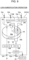
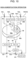
- Figs. 9 and 10 are diagrams illustrating the humidification operation of ventilation device 50.
- Fig. 11 illustrates a timing chart of the humidification operation.
- the humidification operation of ventilation device 50 is performed in a state where at least one of first heater 76A and second heater 76B (in the present exemplary embodiment, first heater 76A) is in operation.
- first heater 76A and second heater 76B operate as illustrated in Fig. 9 .
- both of first heater 76A and second heater 76B operate as illustrated in Fig. 10 .
- both of first fan 66 and second fan 84 rotate during the humidification operation.
- damper 74a closes exhaust port 52e in order to direct outdoor air Aout to indoor unit 20 (IN state).
- outdoor air Aout heated by at least one of first heater 76A and second heater 76B takes moisture retained by absorbent 58 and is supplied to indoor space Rin.
- indoor space Rin is humidified.
- absorbent 58 whose moisture is taken by heated outdoor air Aout collects moisture from outdoor air Aout flowing through flow channel R3.
- Absorbent 58 can thereby continue retaining a certain amount of moisture.
- ventilation device 50 can continue the humidification operation.
- the plurality of heaters (first heater 76A, second heater 76B) as the heating means for outdoor air Aout in this manner, it is possible to more finely adjust the amount of moisture of outdoor air Aout (the amount of moisture taken from absorbent 58) as compared with a case of using one heating means. That is, the humidification level of indoor space Rin can be finely controlled.
- the moisture amount of outdoor air Aout can be adjusted in three stages by turning ON/OFF each of first heater 76A and second heater 76B. As a result, excessive humidification can be prevented, and wasteful power consumption by the heaters can be prevented (as compared with the case of using one heating means).
- first heater 76A and second heater 76B are a heater whose output is adjustable as well as being turned ON/OFF, the moisture amount of outdoor air Aout (the moisture amount taken from absorbent 58) can be more finely adjusted.
- controller 42 illustrated in Fig. 1 is configured to enable the user to set the indoor humidity.
- Indoor unit 20 is provided with indoor humidity sensor 90 that measures the indoor humidity and outputs a measured value of the measured indoor humidity. The outputs of first heater 76A and second heater 76B are controlled such that the indoor humidity (measured value) output by indoor humidity sensor 90 becomes the set value.
- both of first heater 76A and second heater 76B operate at the maximum output.
- a predetermined value for example, 30%
- both of first heater 76A and second heater 76B operate at the maximum output.
- only one of first heater 76A and second heater 76B operates to adjust the output value.
- a rotation speed of first fan 66 may be adjusted in a state where the outputs of first heater 76A and second heater 76B are maintained constant.
- the indoor humidity can be more quickly adjusted although the adjustable range is smaller, as compared with the case where the indoor humidity is adjusted by first heater 76A and second heater 76B.
- the output adjustment of first heater 76A and second heater 76B may be executed on the basis of the moisture amount retained by absorbent 58.
- the moisture amount that outdoor air Aout can take from absorbent 58 and can retain is determined by the temperature of outdoor air Aout, that is, the outputs of first heater 76A and second heater 76B. Therefore, in a case where the moisture amount retained by absorbent 58 is smaller than the moisture amount that can be retained by outdoor air Aout heated by first heater 76A and second heater 76B at the maximum output, heating outdoor air Aout wastefully consumes power.
- the output adjustment of first heater 76A and second heater 76B is preferably executed on the basis of the moisture amount retained by absorbent 58.
- the moisture amount retained by absorbent 58 can be estimated on the basis of, for example, humidity of outdoor space Rout and a rotation time of second fan 84.
- outdoor unit 30 is provided with an outdoor humidity sensor (not illustrated) that measures outdoor humidity.
- second fan 84 may operate for a predetermined time after air conditioner 10 stops an air conditioning operation (after timing Te).
- second fan 84 of ventilation device 50 rotates while fan 24 of indoor unit 20, and fan 34 and compressor 36 of outdoor unit 30 stop.
- absorbent 58 after the stop of the air conditioning operation of air conditioner 10.
- the humidification operation can be reliably performed in a state where absorbent 58 has a sufficient moisture retention amount without any shortage. That is, it is possible to sufficiently and quickly humidify indoor space Rin immediately after the start of the air conditioning operation.
- second fan 84 may start to operate before the start of the air conditioning operation of air conditioner 10 (before timing T0).
- moisture is stored in absorbent 58 before the start of the air conditioning operation of air conditioner 10.
- controller 42 illustrated in Fig. 1 is configured to enable the user to set a time to start the air conditioning operation, and second fan 84 starts to rotate from a predetermined time before the start time.
- the predetermined time is, for example, a time required for the moisture retention amount of absorbent 58 to increase from 0 to the maximum.
- Fig. 12 is a diagram illustrating the dehumidification operation and the regeneration operation of ventilation device 50.
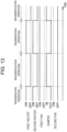
- Fig. 13 is a timing chart of the dehumidification operation and the regeneration operation.
- the dehumidification operation of ventilation device 50 is performed in a state where first heater 76A and second heater 76B stop operating (OFF state).
- first fan 66 rotates and second fan 84 stops during the dehumidification operation.
- damper 74a closes exhaust port 52e in order to direct outdoor air Aout to indoor unit 20 (IN state).
- outdoor air Aout passes through absorbent 58 without being heated.
- the moisture of outdoor air Aout is collected by absorbent 58, and outdoor air Aout is supplied to indoor space Rin in a dried state.
- indoor space Rin is dehumidified.
- absorbent 58 While the dehumidification operation is continued, absorbent 58 continues collecting the moisture of outdoor air Aout. Therefore, absorbent 58 eventually reaches a saturation state in which absorbent 58 cannot retain moisture any more. Therefore, the regeneration operation for regenerating the collecting capacity of absorbent 58 is performed.
- the regeneration operation of ventilation device 50 is performed in a state where first heater 76A and second heater 76B are in operation (ON state).
- first fan 66 rotates and second fan 84 stops during the regeneration operation.
- damper 74a closes exhaust port 52d in order to direct outdoor air Aout not to indoor unit 20 but to outdoor space Rout (OUT state).
- outdoor air Aout heated by both of first heater 76A and second heater 76B takes the moisture retained by absorbent 58 and is discharged to outdoor space Rout.
- absorbent 58 is dried, and its moisture collecting capacity is regenerated.
- the regeneration operation is performed as a set with the dehumidification operation. Specifically, the regeneration operation is performed in a case where the duration of the dehumidification operation is longer than a time until absorbent 58 is saturated. In this case, as illustrated in Fig. 13 , the dehumidification operation and the regeneration operation are alternately performed. As a result, the dehumidification operation is intermittently continued.
- Fig. 14 is a diagram illustrating the ventilation operation of ventilation device 50.
- the ventilation operation of ventilation device 50 is performed in a state where first heater 76A and second heater 76B stop operating (OFF state).
- first fan 66 rotates and second fan 84 stops during the ventilation operation.
- damper 74a closes exhaust port 52e in order to direct outdoor air Aout to indoor unit 20 (IN state).
- outdoor air Aout is directly supplied to indoor space Rin.
- Which one of the humidification operation, the dehumidification operation, and the ventilation operation of ventilation device 50 is to be performed is determined by, for example, the user. For example, when the user selects the operation of ventilation device 50 using controller 42, the operation selected by the user among the humidification operation, the dehumidification operation, and the ventilation operation is performed.
- the humidification operation and the dehumidification operation are selectively performed such that the measured value by indoor humidity sensor 90 becomes the set value.
- the regeneration operation is performed on the basis of the duration of the dehumidification operation or the moisture retention amount of absorbent 58, instead of the operation by the user.
- ventilation conduit 56 illustrated in Fig. 1 When outdoor air Aout flows into ventilation conduit 56 illustrated in Fig. 1 by the operation of ventilation device 50 (particularly, the humidification operation), dew condensation may occur and water may be accumulated in ventilation conduit 56 depending on the surrounding environment or the season. Specifically, water may be accumulated in a lowermost part of ventilation conduit 56.
- ventilation conduit 56 includes fixed pipe 92, ventilation hose (not illustrated), and connector 94.
- Fixed pipe 92 is fixed to the side surface of outdoor unit 30.
- the ventilation hose connects fixed pipe 92 and indoor unit 20.
- Connector 94 is attached to a distal end of the ventilation hose and detachably connected to distal end 92a of fixed pipe 92. Since distal end 92a of fixed pipe 92 is located at the lowest position in ventilation conduit 56, there is a possibility that water is accumulated in distal end 92a of fixed pipe 92.
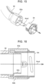
- Fig. 15 is an exploded view of a portion of ventilation conduit 56.
- Fig. 16 is a sectional view of a portion of ventilation conduit 56.
- through hole 92b is formed in a lowermost part of distal end 92a of fixed pipe 92. That is, ventilation conduit 56 has through hole 92b in the lowermost part of ventilation conduit 56. Water accumulated in ventilation conduit 56 is discharged to the outside through through hole 92b.
- fixed pipe 92 that is, ventilation conduit 56
- hood 92c has a semi-cylindrical shape, but may have another shape such as a triangular shape, a rectangular shape, or a polygonal shape, for example.
- a flow channel of water that enters hood 92c and reaches through hole 92b is provided such that a direction in which water flows is opposite to a direction of outdoor air Aout.
- outdoor air Aout is prevented from entering hood 92c and unnecessarily escaping from through hole 92b.
- through hole 92b desirably has a diameter more than or equal to 2.5 mm. This is to prevent a waterdrop, which has a diameter of about 2 mm, from bridging and blocking through hole 92b.
- air conditioner 10 can sufficiently and quickly humidify indoor space Rin immediately after the start of the air conditioning operation.
- Air conditioner 10 is the air conditioner including indoor unit 20 and outdoor unit 30.
- Air conditioner 10 according to the exemplary embodiment of the present disclosure includes absorbent 58, the first flow channel (flow channel R1, flow channel R2), the second flow channel (flow channel R3), first fan 66, second fan 84, and the heater (first heater 76A, second heater 76B).
- flow channel R1 and flow channel R2 are examples of the first flow channel according to the present disclosure
- flow channel R3 is an example of the second flow channel according to the present disclosure.
- first heater 76A and second heater 76B are examples of the heater according to the present disclosure.
- Absorbent 58 absorbs the moisture of outdoor air Aout.
- the first flow channel passes through absorbent 58 to connect outdoor space Rout and the inside of indoor unit 20, and allows outdoor air Aout to flow.
- the second flow channel passes through absorbent 58, and allows outdoor air Aout to flow from outdoor space Rout to outdoor space Rout.
- First fan 66 generates the flow of outdoor air Aout toward indoor unit 20 in the first flow channel (flow channel R1, flow channel R2).
- Second fan 84 generates the flow of outdoor air Aout in the second flow channel (flow channel R3).
- the heater (first heater 76A, second heater 76B) heats outdoor air Aout on the upstream side relative to absorbent 58 in the first flow channel (flow channel R1, flow channel R2).
- Air conditioner 10 is configured to be able to perform the humidification operation with the heater (first heater 76A, second heater 76B) heating outdoor air Aout, and heated outdoor air Aout taking the moisture from absorbent 58 and flowing toward indoor unit 20.
- second fan 84 operates for the predetermined time to cause absorbent 58 to retain the moisture.
- second fan 84 may operate for the predetermined time after the stop of the operation other than the humidification operation, that is, after the stop of the air conditioning operation. Conversely, second fan 84 may operate for the predetermined time only after the stop of the humidification operation of air conditioner 10.
- absorbent 58 is the polymeric sorbent.
- air conditioner 10 according to the exemplary embodiment of the present disclosure further includes controller 42 that enables the user to set the time to start the air conditioning operation, and second fan 84 starts to operate before the time to start the air conditioning operation.
- the heater (first heater 76A, second heater 76B) is the PTC heater.
- the first flow channel (flow channel R1, flow channel R2) includes the labyrinth that allows outdoor air Aout to pass.
- air conditioner 10 according to the exemplary embodiment of the present disclosure includes indoor unit 20 and outdoor unit 30, and outdoor unit 30 includes ventilation device 50.
- air conditioner 10 according to the exemplary embodiment of the present disclosure may be modified such that outdoor unit 30 and ventilation device 50 are configured separately, that is, air conditioner 10 includes indoor unit 20, outdoor unit 30, and ventilation device 50 (first modification).
- air conditioner 10 according to the exemplary embodiment of the present disclosure may be modified so as to include indoor unit 20 and outdoor unit 30, and have at least the following configuration (second modification).
- the air conditioner according to the second modification includes at least absorbent 58, the first flow channel (flow channel R1, flow channel R2), the second flow channel (flow channel R3), first fan 66, second fan 84, and the heater (first heater 76A, second heater 76B).
- air conditioner 10 according to the exemplary embodiment of the present disclosure and the air conditioners according to the first and second modifications described above have been described as including the two flow channels (flow channel R1, flow channel R2) and the two heaters (first heater 76A, second heater 76B).
- air conditioner 10 according to the exemplary embodiment of the present disclosure and the air conditioners according to the first and second modifications described above may be modified into a configuration including flow channel R1 and first heater 76A, or a configuration including flow channel R2 and second heater 76B (third modification). That is, for example, the air conditioner according to the third modification includes the first flow channel (flow channel R1) and the heater (first heater 76A).
- the first flow channel (flow channel R1) passes through absorbent 58 to connect outdoor space Rout and the inside of indoor unit 20, and allows outdoor air Aout to flow.
- the heater (first heater 76A) heats outdoor air Aout on the upstream side relative to absorbent 58 in the first flow channel (flow channel R1).
- first heater 76A and second heater 76B are provided as the heating means for heating outdoor air Aout.
- the number of heaters as the heating means is not limited thereto.
- the number of means for heating outdoor air Aout may be one.
- the dehumidification operation is performed to lower the indoor humidity.
- the purpose of performing the dehumidification operation is not limited thereto.
- the dehumidification operation may be performed to dry heat exchanger 22 of indoor unit 20 to which waterdrops adhere after the cooling operation.
- indoor unit 20 is configured such that outdoor air Aout dried by the dehumidification operation is blown toward heat exchanger 22.
- the air conditioner according to the exemplary embodiment of the present disclosure is an air conditioner including an indoor unit and an outdoor unit, the air conditioner including an absorbent, a first flow channel, a second flow channel, a first fan, a second fan, and a heater.
- the absorbent absorbs moisture of outdoor air.
- the first flow channel passes through the absorbent to connect an outdoor space and an inside of the indoor unit, and allows the outdoor air to flow.
- the second flow channel passes through the absorbent, and allows the outdoor air to flow from the outdoor space to the outdoor space.
- the first fan generates a flow of the outdoor air toward the indoor unit in the first flow channel.
- the second fan generates a flow of the outdoor air in the second flow channel.
- the heater heats the outdoor air on an upstream side relative to the absorbent in the first flow channel.
- the air conditioner according to the exemplary embodiment of the present disclosure is configured to be able to perform a humidification operation with the heater heating the outdoor air, and the heated outdoor air taking the moisture from the absorbent and flowing toward the indoor unit. After the air conditioner according to the exemplary embodiment of the present disclosure stops an air conditioning operation, the second fan operates for a predetermined time to cause the absorbent to retain the moisture.
- the present disclosure is applicable to any air conditioner including an indoor unit and an outdoor unit.
Landscapes
- Engineering & Computer Science (AREA)
- Chemical & Material Sciences (AREA)
- Combustion & Propulsion (AREA)
- Mechanical Engineering (AREA)
- General Engineering & Computer Science (AREA)
- General Chemical & Material Sciences (AREA)
- Thermal Sciences (AREA)
- Analytical Chemistry (AREA)
- Physics & Mathematics (AREA)
- Oil, Petroleum & Natural Gas (AREA)
- Chemical Kinetics & Catalysis (AREA)
- Drying Of Gases (AREA)
- Air Conditioning Control Device (AREA)
- Ventilation (AREA)
- Duct Arrangements (AREA)
- Devices For Blowing Cold Air, Devices For Blowing Warm Air, And Means For Preventing Water Condensation In Air Conditioning Units (AREA)
- Air Humidification (AREA)
Abstract
Description
- The present disclosure relates to an air conditioner.
- Conventionally, as described in PTL 1, there has been known an air conditioner including an indoor unit disposed inside a room to be air-conditioned, and an outdoor unit disposed outside the room. The air conditioner is configured to be able to supply humidified outdoor air from the outdoor unit to the indoor unit.
- PTL 1: Unexamined
Japanese Patent Publication No. 2001-91000 - By the way, the air conditioner is sometimes required to perform a humidification operation of supplying humidified outdoor air into a room immediately after starting an air conditioning operation. However, in the case of the air conditioner described in PTL 1, there is a possibility that indoor humidification cannot be performed sufficiently and quickly due to a shortage of moisture retained by an adsorbent.
- Therefore, an object of the present disclosure is to provide an air conditioner capable of sufficiently and quickly performing indoor humidification immediately after starting an air conditioning operation.
- An air conditioner according to the present disclosure is an air conditioner including an indoor unit and an outdoor unit, the air conditioner including an absorbent, a first flow channel, a second flow channel, a first fan, a second fan, and a heater. The absorbent absorbs moisture of outdoor air. The first flow channel passes through the absorbent to connect an outdoor space and an inside of the indoor unit, and allows the outdoor air to flow. The second flow channel passes through the absorbent, and allows the outdoor air to flow from the outdoor space to the outdoor space. The first fan generates a flow of the outdoor air toward the indoor unit in the first flow channel. The second fan generates a flow of the outdoor air in the second flow channel. The heater heats the outdoor air on an upstream side relative to the absorbent in the first flow channel. The air conditioner according to the present disclosure is configured to be able to perform a humidification operation with the heater heating the outdoor air, and the heated outdoor air taking the moisture from the absorbent and flowing toward the indoor unit. After the air conditioner according to the present disclosure stops an air conditioning operation, the second fan operates for a predetermined time to cause the absorbent to retain the moisture.
- The air conditioner according to the present disclosure can sufficiently and quickly perform the indoor humidification immediately after starting the air conditioning operation.
-
-
Fig. 1 is a schematic configuration diagram of an air conditioner according to an exemplary embodiment of the present disclosure. -
Fig. 2 is a perspective view illustrating an outer appearance of an outdoor unit according to the exemplary embodiment. -
Fig. 3 is a perspective view illustrating an internal configuration of a ventilation device according to the exemplary embodiment. -
Fig. 4 is a perspective view of the ventilation device according to the exemplary embodiment from which some of its components are removed. -
Fig. 5 is a top view of the ventilation device according to the exemplary embodiment from which some of its components are removed. -
Fig. 6 is an exploded perspective view of the ventilation device according to the exemplary embodiment. -
Fig. 7 is an exploded perspective view of some components of the ventilation device according to the exemplary embodiment as viewed from a different viewpoint. -
Fig. 8 is a schematic sectional view of the ventilation device according to the exemplary embodiment. -
Fig. 9 is a diagram illustrating a humidification operation (low-humidification operation) of the ventilation device according to the exemplary embodiment. -
Fig. 10 is a diagram illustrating a humidification operation (high-humidification operation) of the ventilation device according to the exemplary embodiment. -
Fig. 11 is a timing chart of the humidification operation of the ventilation device according to the exemplary embodiment. -
Fig. 12 is a diagram illustrating a dehumidification operation and a regeneration operation of the ventilation device according to the exemplary embodiment. -
Fig. 13 is a timing chart of the dehumidification operation and the regeneration operation of the ventilation device according to the exemplary embodiment. -
Fig. 14 is a diagram illustrating a ventilation operation of the ventilation device according to the exemplary embodiment. -
Fig. 15 is an exploded view of a portion of a ventilation conduit according to the exemplary embodiment. -
Fig. 16 is a sectional view of a portion of the ventilation conduit according to the exemplary embodiment. - An air conditioner according to the present disclosure is an air conditioner including an indoor unit and an outdoor unit, the air conditioner including an absorbent, a first flow channel, a second flow channel, a first fan, a second fan, and a heater. The absorbent absorbs moisture of outdoor air. The first flow channel passes through the absorbent to connect an outdoor space and an inside of the indoor unit, and allows the outdoor air to flow. The second flow channel passes through the absorbent, and allows the outdoor air to flow from the outdoor space to the outdoor space. The first fan generates a flow of the outdoor air toward the indoor unit in the first flow channel. The second fan generates a flow of the outdoor air in the second flow channel. The heater heats the outdoor air on an upstream side relative to the absorbent in the first flow channel. The air conditioner according to the present disclosure is configured to be able to perform a humidification operation with the heater heating the outdoor air, and the heated outdoor air taking the moisture from the absorbent and flowing toward the indoor unit. After the air conditioner according to the present disclosure stops an air conditioning operation, the second fan operates for a predetermined time to cause the absorbent to retain the moisture.
- The air conditioner according to the present disclosure can sufficiently and quickly perform the indoor humidification immediately after starting the air conditioning operation.
- Furthermore, for example, in the air conditioner according to the present disclosure, the absorbent may be a polymeric sorbent.
- Furthermore, for example, the air conditioner according to the present disclosure may further include a controller that enables a user to set a time to start the air conditioning operation, and the second fan may start to operate before the time to start the air conditioning operation.
- In addition, for example, in the air conditioner according to the present disclosure, the heater may be a positive temperature coefficient (PTC) heater.
- Moreover, for example, in the air conditioner according to the present disclosure, the first flow channel may include a labyrinth that allows the outdoor air to pass.
- Hereinafter, one exemplary embodiment of the present disclosure will be described with reference to the drawings. Hereinafter, a Z-axis direction (vertical direction) in each drawing may be described as an upper/lower direction.
- First, a configuration of
air conditioner 10 according to the present exemplary embodiment will be described with reference toFig. 1 . -
Fig. 1 is a schematic configuration diagram ofair conditioner 10. - As illustrated in
Fig. 1 ,air conditioner 10 includesindoor unit 20 that is disposed in indoor space Rin to be air-conditioned, andoutdoor unit 30 that is disposed in outdoor space Rout. -
Indoor unit 20 is provided with heat exchanger 22 andfan 24. Heat exchanger 22 performs heat exchange with indoor air Ain of indoor space Rin.Fan 24 draws indoor air Ain intoindoor unit 20 and blows the air heat-exchanged with heat exchanger 22 into indoor space Rin. -
Outdoor unit 30 is provided withheat exchanger 32,fan 34, compressor 36, andexpansion valve 38.Heat exchanger 32 performs heat exchange with outdoor air Aout of outdoor space Rout.Fan 34 generates a flow of outdoor air Aout passing throughheat exchanger 32. - Heat exchanger 22 of
indoor unit 20 andheat exchanger 32, compressor 36, andexpansion valve 38 ofoutdoor unit 30 are connected byrefrigerant pipe 40 to constitute a refrigeration cycle ofair conditioner 10. With this refrigeration cycle,air conditioner 10 performs a heating operation of blowing heated indoor air Ain into indoor space Rin, a cooling operation of blowing cooled indoor air Ain into indoor space Rin, and a dehumidification operation of blowing dehumidified indoor air Ain into indoor space Rin. In the case of the present exemplary embodiment,air conditioner 10 includescontroller 42 that enables a user to select the operation ofair conditioner 10 such as the heating operation, the cooling operation, and the dehumidification operation, and to set parameters and the like necessary for the operation, such as temperature setting. - Furthermore,
outdoor unit 30 ofair conditioner 10 includesventilation device 50 that supplies outdoor air Aout into indoor space Rin, that is, ventilates indoor space Rin. Although the present exemplary embodiment is described such thatoutdoor unit 30 includesventilation device 50,ventilation device 50 does not have to be included inoutdoor unit 30. - Next, a configuration of
ventilation device 50 will be described with reference toFigs. 2 to 8 . -
Fig. 2 is a perspective view illustrating an outer appearance ofoutdoor unit 30. In addition,Fig. 3 is a perspective view illustrating an internal configuration ofventilation device 50. Furthermore,Figs. 4 and5 are a perspective view and a top view ofventilation device 50 from which some of its components are removed. Moreover,Fig. 6 is an exploded perspective view ofventilation device 50. In addition,Fig. 7 is an exploded perspective view of some components ofventilation device 50 as viewed from a different viewpoint. Furthermore,Fig. 8 is a schematic sectional view ofventilation device 50. - In the case of the present exemplary embodiment, as illustrated in
Fig. 2 andFig. 3 ,ventilation device 50 hashousing 52 with an open top, andtop panel 54 that is a lid ofhousing 52.Housing 52 ofventilation device 50 includes a plurality ofintake ports exhaust ports Intake ports housing 52.Exhaust ports housing 52 to the outside.Ventilation conduit 56 illustrated inFig. 2 is connected to exhaustport 52d. As illustrated inFig. 2 ,ventilation conduit 56 is attached to a side surface ofoutdoor unit 30 and is coupled to a ventilation hose that communicates withindoor unit 20. That is,ventilation conduit 56 connects the inside ofoutdoor unit 30 and the inside ofindoor unit 20. Remainingexhaust ports - As illustrated in
Figs. 4 ,5 ,6 , and8 ,ventilation device 50 includes absorbent 58 that absorbs moisture of outdoor air Aout, at the center inhousing 52. -
Absorbent 58 is a member through which air can pass, and is a member that collects moisture from the passing air or gives moisture to the passing air. In the case of the present exemplary embodiment, absorbent 58 is a disk-shaped member that enables the air passage in the vertical direction (Z-axis direction) and that rotates about rotation center line C1 extending in the vertical direction. As illustrated inFig. 6 ,absorbent 58 is held bycylindrical holder 60, and is rotated byabsorbent motor 64.Absorbent motor 64 includesgear 62 that meshes with external teeth ofholder 60. During operation ofventilation device 50,absorbent 58 continues rotating at a constant rotation speed. - Note that absorbent 58 is preferably formed of a polymeric sorbent that sorbs moisture in the air. The polymeric sorbent is composed of, for example, crosslinked sodium polyacrylate. The polymeric sorbent has a higher rate of absorbing moisture, can desorb the moisture retained therein at a lower heating temperature, and can retain the moisture for a longer time, than an adsorbent such as silica gel or zeolite can.
- As illustrated in
Figs. 6 ,7 , and8 ,ventilation device 50 also includesfirst fan 66 that draws outdoor air Aout intoventilation device 50, causes outdoor air Aout to pass through absorbent 58, and blows outdoor air Aout having passed throughabsorbent 58 towardindoor unit 20. -
First fan 66 is disposed on one side in a longitudinal direction (Y-axis direction) ofventilation device 50 relative toabsorbent 58.First fan 66 is, for example, a sirocco fan.First fan 66 is accommodated incylindrical part 68a that is provided inpartition wall plate 68.Partition wall plate 68 divides a space on one side in the longitudinal direction relative to absorbent 58 into upper and lower spaces. As illustrated inFig. 8 ,partition wall plate 68 forms upper space S 1 in contact with a portion ofupper surface 58a ofabsorbent 58, and lower space S2 in contact with a portion oflower surface 58b ofabsorbent 58. -
Opening 68b connected to exhaustport 52d andopening 68c connected to exhaustport 52e are formed incylindrical part 68a ofpartition wall plate 68. Throughhole 68d for drawing air intofirst fan 66 incylindrical part 68a is also formed inpartition wall plate 68. - In addition,
fan cover 70 that coversfirst fan 66 is attached tocylindrical part 68a ofpartition wall plate 68.Fan cover 70 is provided withmotor 72 that rotatesfirst fan 66. As illustrated inFig. 7 ,fan cover 70 is also provided withdamper device 74 that closes one ofopening 68b andopening 68c ofpartition wall plate 68.Damper device 74 includesturnable damper 74a, and is configured to close one ofopening 68b andopening 68c ofpartition wall plate 68 by turningdamper 74a. - When
motor 72 rotatesfirst fan 66, outdoor air Aout flows intohousing 52 throughintake ports housing 52 as illustrated inFig. 4 . Specifically, as illustrated inFig. 8 , outdoor air Aout inflowing through each ofintake ports partition wall plate 68 and flows toward an upper portion ofabsorbent 58. Subsequently, outdoor air Aout passes through absorbent 58 fromupper surface 58a towardlower surface 58b ofabsorbent 58. Outdoor air Aout having passed throughabsorbent 58 moves in lower space S2 belowpartition wall plate 68, and passes through throughhole 68d ofpartition wall plate 68 to be drawn intofirst fan 66. Outdoor air Aout drawn intofirst fan 66 passes through one ofopening 68b andopening 68c that is not closed bydamper 74a ofdamper device 74. That is, outdoor air Aout passes throughexhaust port 52d and finally reaches the inside ofindoor unit 20, or is discharged to outdoor space Rout throughexhaust port 52e. As described above,first fan 66 draws outdoor air Aout intooutdoor unit 30, and sends drawn outdoor air Aout towardindoor unit 20 throughventilation conduit 56. - In the case of the present exemplary embodiment, as illustrated in
Fig. 4 andFig. 5 ,fan cover 70 andmotor 72 are disposed betweenintake port 52a andintake port 52b ofhousing 52. Therefore, there are substantially two flow channels that pass throughabsorbent 58 to connect outdoor space Rout and the inside ofindoor unit 20, that is, connect withventilation conduit 56, and allow outdoor air Aout to flow. As illustrated inFig. 6 , two flow channels R1, R2 include a merging channel where the two flow channels merge with each other after passing throughabsorbent 58.First fan 66 is provided in the merging channel. That is,first fan 66 generates a flow of outdoor air Aout towardindoor unit 20 in flow channels R1, R2. As illustrated inFig. 5 ,ventilation device 50 includesfirst heater 76A andsecond heater 76B.First heater 76A is provided in flow channel R1 starting fromintake port 52a.Second heater 76B is provided in flow channel R2 starting fromintake port 52b. The reason whyventilation device 50 is provided with the plurality of flow channels for outdoor air Aout flowing towardindoor unit 20, andfirst heater 76A andsecond heater 76B are respectively provided in the flow channels will be described later. - As illustrated in
Fig. 4 andFig. 5 ,first heater 76A andsecond heater 76B are disposed nearabsorbent 58. Specifically,first heater 76A andsecond heater 76B are disposed on the upstream side relative to absorbent 58 in flow channels R1, R2 of outdoor air Aout. In the case of the present exemplary embodiment,first heater 76A andsecond heater 76B are provided on partition wall plate 78 (seeFig. 6 ). - In addition, as illustrated in
Fig. 4 ,first heater 76A,second heater 76B, and a portion ofupper surface 58a ofabsorbent 58 where flow channels R1, R2 pass are covered withheater cover 80. As a result, outdoor air Aout heated byfirst heater 76A andsecond heater 76B can pass throughabsorbent 58. Note that the details of the heating of outdoor air Aout byfirst heater 76A andsecond heater 76B will be described later. -
First heater 76A andsecond heater 76B may be heaters having the same heating capacity or heaters having different heating capacities. In addition,first heater 76A andsecond heater 76B are preferably PTC heaters in which electrical resistance increases with an increase in temperature when a current flows, that is, the PTC heaters capable of preventing an excessive increase in heating temperature. A heater using nichrome wires, carbon fibers, or the like may be used. In this case, since the heating temperature (surface temperature) continues rising as the current flows continuously, it is necessary to monitor the temperature. On the other hand, in the case of the PTC heater, the heater itself adjusts the heating temperature within a certain temperature range, and thus, it is not necessary to monitor the heating temperature. In this respect, the PTC heater is more preferable. - As illustrated in
Fig. 8 ,first heater 76A andsecond heater 76B are covered withheater cover 80. Therefore, in order to enterfirst heater 76A andsecond heater 76B, outdoor air Aout flowing through flow channels R1, R2 first descends along an outer side surface ofside wall 80a. Outdoor air Aout subsequently enters a gap and moves upward. Outdoor air Aout then moves throughfirst heater 76A andsecond heater 76B. After that, outdoor air Aout descends towardupper surface 58a ofabsorbent 58. That is, two flow channels R1, R2 include a labyrinth through which outdoor air Aout passes. - Since flow channels R1, R2 through which outdoor air Aout flows include the labyrinth through which outdoor air Aout passes, it is possible to prevent dust, sand, and the like contained in outdoor air Aout from reaching
ventilation conduit 56,indoor unit 20, and indoor space Rin. That is, when outdoor air Aout moves through the labyrinth, dust, sand, and the like are separated from outdoor air Aout by gravity.Tray 82 is provided in a portion ofpartition wall plate 78 nearfirst heater 76A andsecond heater 76B.Tray 82 receives and collects the dust and the like separated from outdoor air Aout. - As illustrated in
Figs. 4 ,5 ,6 , and8 ,ventilation device 50 includes flow channel R3 other than flow channels R1, R2, as a flow channel of outdoor air Aout. - Unlike flow channels R1, R2, flow channel R3 of outdoor air Aout is not connected to the inside of
indoor unit 20. Flow channel R3 is a flow channel that passes throughabsorbent 58 and allows outdoor air Aout to flow from outdoor space Rout to outdoor space Rout. - Specifically, flow channel R3 starts from
intake port 52c, passes through absorbent 58 fromlower surface 58b towardupper surface 58a, and reachesexhaust port 52f.Ventilation device 50 includessecond fan 84 that generates a flow of outdoor air Aout in flow channel R3. - As illustrated in
Fig. 6 ,second fan 84 is disposed on the other side in the longitudinal direction (Y-axis direction) ofventilation device 50 relative toabsorbent 58.Second fan 84 is, for example, a sirocco fan.Second fan 84 is rotated bymotor 86 that is attached to an outer side surface ofbottom plate 52g ofhousing 52. In addition,second fan 84 is accommodated incylindrical part 52h that is provided on an inner side surface ofbottom plate 52g ofhousing 52. An inner space ofcylindrical part 52h communicates withexhaust port 52f. - In addition,
partition wall plate 78 that coverssecond fan 84 is mounted oncylindrical part 52h ofhousing 52.Partition wall plate 78 divides a space on the other side in the longitudinal direction (Y-axis direction) relative to absorbent 58 into upper and lower spaces. In addition,partition wall plate 78 has throughhole 78a for drawing outdoor air Aout intosecond fan 84.Partition wall plate 78 is further provided with absorbentaccommodating part 78b that rotatably accommodates absorbent 58 without coveringupper surface 58a. - When
motor 86 rotatessecond fan 84, outdoor air Aout flows intohousing 52 throughintake port 52c ofhousing 52 as illustrated inFig. 4 . Specifically, as illustrated inFig. 8 , outdoor air Aout inflowing throughintake port 52c flows into lower space S4 belowpartition wall plate 78 and flows toward a lower portion ofabsorbent 58. Subsequently, outdoor air Aout passes through absorbent 58 fromlower surface 58b towardupper surface 58a ofabsorbent 58. Outdoor air Aout having passed throughabsorbent 58 moves in upper space S3 abovepartition wall plate 78, and passes through throughhole 78a ofpartition wall plate 78 to be drawn intosecond fan 84. Outdoor air Aout drawn intosecond fan 84 is discharged to outdoor space Rout throughexhaust port 52f. - To block the flow of outdoor air Aout between lower space S2 and lower space S4 below
absorbent 58,housing 52 includesseal 52j onbottom plate 52g as illustrated inFigs. 6 and8 . In addition, to block the flow of outdoor air Aout between upper spaces S1, S3 aboveabsorbent 58,partition wall plate 78 includesseal 78c, and sealingmember 88 that seals a gap betweenpartition wall plate 78 andtop panel 54 is provided betweenpartition wall plate 78 andtop panel 54. As a result, outdoor air Aout flowing through flow channels R1, R2 and outdoor air Aout flowing through flow channel R3 can pass throughabsorbent 58 at different positions, and are prevented from being mixed with each other. - The configuration of
ventilation device 50 has been described so far. An operation ofventilation device 50 will be described below with reference toFigs. 9 to 14 . -
Ventilation device 50 is configured to perform a humidification operation, a dehumidification operation, a regeneration operation, and a ventilation operation described below. Specifically,ventilation device 50 includes a control device that performs the humidification operation, the dehumidification operation, the regeneration operation, and the ventilation operation by controllingfirst fan 66,second fan 84,first heater 76A,second heater 76B, damper device 74 (damper 74a), and the like. The control device includes, for example, a computer system including a processor and a memory. The processor executes a program stored in the memory, and thus, the computer system functions as the control device. Here, the program executed by the processor is assumed to be recorded in advance in the memory of the computer system. The program may be provided by being recorded in a non-transitory recording medium such as a memory card, or may be provided through a telecommunication line such as the Internet. -
Figs. 9 and10 are diagrams illustrating the humidification operation ofventilation device 50. In addition,Fig. 11 illustrates a timing chart of the humidification operation. - As illustrated in
Figs. 9 ,10 , and11 , the humidification operation ofventilation device 50 is performed in a state where at least one offirst heater 76A andsecond heater 76B (in the present exemplary embodiment,first heater 76A) is in operation. When indoor humidity of indoor space Rin is to be increased a little (low-humidification operation), at least one offirst heater 76A andsecond heater 76B operates as illustrated inFig. 9 . On the other hand, when the indoor humidity of indoor space Rin is to be increased a lot (high-humidification operation), both offirst heater 76A andsecond heater 76B operate as illustrated inFig. 10 . In addition, both offirst fan 66 andsecond fan 84 rotate during the humidification operation. Furthermore, during the humidification operation,damper 74a closesexhaust port 52e in order to direct outdoor air Aout to indoor unit 20 (IN state). - According to such a humidification operation, outdoor air Aout heated by at least one of
first heater 76A andsecond heater 76B takes moisture retained byabsorbent 58 and is supplied to indoor space Rin. As a result, indoor space Rin is humidified. In addition, absorbent 58 whose moisture is taken by heated outdoor air Aout collects moisture from outdoor air Aout flowing through flow channel R3.Absorbent 58 can thereby continue retaining a certain amount of moisture. As a result,ventilation device 50 can continue the humidification operation. - By using the plurality of heaters (
first heater 76A,second heater 76B) as the heating means for outdoor air Aout in this manner, it is possible to more finely adjust the amount of moisture of outdoor air Aout (the amount of moisture taken from absorbent 58) as compared with a case of using one heating means. That is, the humidification level of indoor space Rin can be finely controlled. For example, in a case wherefirst heater 76A andsecond heater 76B are of the type operating at a constant temperature, the moisture amount of outdoor air Aout can be adjusted in three stages by turning ON/OFF each offirst heater 76A andsecond heater 76B. As a result, excessive humidification can be prevented, and wasteful power consumption by the heaters can be prevented (as compared with the case of using one heating means). - In a case where each of
first heater 76A andsecond heater 76B is a heater whose output is adjustable as well as being turned ON/OFF, the moisture amount of outdoor air Aout (the moisture amount taken from absorbent 58) can be more finely adjusted. As a result, in a case where the indoor humidity is maintained at a set value set by the user, it is easy to maintain the set value. In this case,controller 42 illustrated inFig. 1 is configured to enable the user to set the indoor humidity.Indoor unit 20 is provided withindoor humidity sensor 90 that measures the indoor humidity and outputs a measured value of the measured indoor humidity. The outputs offirst heater 76A andsecond heater 76B are controlled such that the indoor humidity (measured value) output byindoor humidity sensor 90 becomes the set value. For example, when a difference between the measured value byindoor humidity sensor 90 and the set value is larger than a predetermined value (for example, 30%), both offirst heater 76A andsecond heater 76B operate at the maximum output. For example, when the difference between the measured value byindoor humidity sensor 90 and the set value is smaller than the predetermined value, only one offirst heater 76A andsecond heater 76B operates to adjust the output value. - In addition, for example, when the measured value by
indoor humidity sensor 90 substantially matches the set value, a rotation speed offirst fan 66 may be adjusted in a state where the outputs offirst heater 76A andsecond heater 76B are maintained constant. By adjusting the rotation speed offirst fan 66 on the basis of the measured value byindoor humidity sensor 90, the indoor humidity can be more quickly adjusted although the adjustable range is smaller, as compared with the case where the indoor humidity is adjusted byfirst heater 76A andsecond heater 76B. - Furthermore, the output adjustment of
first heater 76A andsecond heater 76B may be executed on the basis of the moisture amount retained byabsorbent 58. The moisture amount that outdoor air Aout can take fromabsorbent 58 and can retain is determined by the temperature of outdoor air Aout, that is, the outputs offirst heater 76A andsecond heater 76B. Therefore, in a case where the moisture amount retained byabsorbent 58 is smaller than the moisture amount that can be retained by outdoor air Aout heated byfirst heater 76A andsecond heater 76B at the maximum output, heating outdoor air Aout wastefully consumes power. In order to prevent such wasteful power consumption of the heaters, the output adjustment offirst heater 76A andsecond heater 76B is preferably executed on the basis of the moisture amount retained byabsorbent 58. Note that the moisture amount retained byabsorbent 58 can be estimated on the basis of, for example, humidity of outdoor space Rout and a rotation time ofsecond fan 84. In this case,outdoor unit 30 is provided with an outdoor humidity sensor (not illustrated) that measures outdoor humidity. - Furthermore, as illustrated in
Fig. 11 ,second fan 84 may operate for a predetermined time afterair conditioner 10 stops an air conditioning operation (after timing Te). In this case,second fan 84 ofventilation device 50 rotates whilefan 24 ofindoor unit 20, andfan 34 and compressor 36 ofoutdoor unit 30 stop. As a result, moisture is stored inabsorbent 58 after the stop of the air conditioning operation ofair conditioner 10. As a result, in a case where the humidification operation is performed at the same time as the start of the subsequent air conditioning operation, the humidification operation can be reliably performed in a state where absorbent 58 has a sufficient moisture retention amount without any shortage. That is, it is possible to sufficiently and quickly humidify indoor space Rin immediately after the start of the air conditioning operation. - In addition, as illustrated in
Fig. 11 ,second fan 84 may start to operate before the start of the air conditioning operation of air conditioner 10 (before timing T0). As a result, moisture is stored inabsorbent 58 before the start of the air conditioning operation ofair conditioner 10. As a result, in a case where the humidification operation is performed at the same time as the start of the subsequent air conditioning operation, the humidification operation can be reliably performed in a state where absorbent 58 has a sufficient moisture retention amount without any shortage. In this case,controller 42 illustrated inFig. 1 is configured to enable the user to set a time to start the air conditioning operation, andsecond fan 84 starts to rotate from a predetermined time before the start time. The predetermined time is, for example, a time required for the moisture retention amount ofabsorbent 58 to increase from 0 to the maximum. - Next, the dehumidification operation and the regeneration operation of
ventilation device 50 will be described. -
Fig. 12 is a diagram illustrating the dehumidification operation and the regeneration operation ofventilation device 50. In addition,Fig. 13 is a timing chart of the dehumidification operation and the regeneration operation. - As illustrated in
Figs. 12 and13 , the dehumidification operation ofventilation device 50 is performed in a state wherefirst heater 76A andsecond heater 76B stop operating (OFF state). In addition,first fan 66 rotates andsecond fan 84 stops during the dehumidification operation. During the dehumidification operation,damper 74a closesexhaust port 52e in order to direct outdoor air Aout to indoor unit 20 (IN state). - According to such a dehumidification operation, outdoor air Aout passes through
absorbent 58 without being heated. As a result, the moisture of outdoor air Aout is collected byabsorbent 58, and outdoor air Aout is supplied to indoor space Rin in a dried state. As a result, indoor space Rin is dehumidified. - While the dehumidification operation is continued, absorbent 58 continues collecting the moisture of outdoor air Aout. Therefore, absorbent 58 eventually reaches a saturation state in which absorbent 58 cannot retain moisture any more. Therefore, the regeneration operation for regenerating the collecting capacity of
absorbent 58 is performed. - As illustrated in
Figs. 12 and13 , the regeneration operation ofventilation device 50 is performed in a state wherefirst heater 76A andsecond heater 76B are in operation (ON state). In addition,first fan 66 rotates andsecond fan 84 stops during the regeneration operation. During the regeneration operation,damper 74a closesexhaust port 52d in order to direct outdoor air Aout not toindoor unit 20 but to outdoor space Rout (OUT state). - According to such a regeneration operation, outdoor air Aout heated by both of
first heater 76A andsecond heater 76B takes the moisture retained byabsorbent 58 and is discharged to outdoor space Rout. As a result, absorbent 58 is dried, and its moisture collecting capacity is regenerated. - The regeneration operation is performed as a set with the dehumidification operation. Specifically, the regeneration operation is performed in a case where the duration of the dehumidification operation is longer than a time until
absorbent 58 is saturated. In this case, as illustrated inFig. 13 , the dehumidification operation and the regeneration operation are alternately performed. As a result, the dehumidification operation is intermittently continued. -
Fig. 14 is a diagram illustrating the ventilation operation ofventilation device 50. - As illustrated in
Fig. 14 , the ventilation operation ofventilation device 50 is performed in a state wherefirst heater 76A andsecond heater 76B stop operating (OFF state). In addition,first fan 66 rotates andsecond fan 84 stops during the ventilation operation. During the ventilation operation,damper 74a closesexhaust port 52e in order to direct outdoor air Aout to indoor unit 20 (IN state). - According to such a ventilation operation, outdoor air Aout is directly supplied to indoor space Rin.
- As a result, indoor space Rin is ventilated.
- Which one of the humidification operation, the dehumidification operation, and the ventilation operation of
ventilation device 50 is to be performed is determined by, for example, the user. For example, when the user selects the operation ofventilation device 50 usingcontroller 42, the operation selected by the user among the humidification operation, the dehumidification operation, and the ventilation operation is performed. In addition, in a case whereair conditioner 10 is configured such that the user can set the indoorhumidity using controller 42, the humidification operation and the dehumidification operation are selectively performed such that the measured value byindoor humidity sensor 90 becomes the set value. Note that the regeneration operation is performed on the basis of the duration of the dehumidification operation or the moisture retention amount ofabsorbent 58, instead of the operation by the user. - When outdoor air Aout flows into
ventilation conduit 56 illustrated inFig. 1 by the operation of ventilation device 50 (particularly, the humidification operation), dew condensation may occur and water may be accumulated inventilation conduit 56 depending on the surrounding environment or the season. Specifically, water may be accumulated in a lowermost part ofventilation conduit 56. - In the case of the present exemplary embodiment, as illustrated in
Fig. 2 ,ventilation conduit 56 includes fixedpipe 92, ventilation hose (not illustrated), andconnector 94.Fixed pipe 92 is fixed to the side surface ofoutdoor unit 30. The ventilation hose connects fixedpipe 92 andindoor unit 20.Connector 94 is attached to a distal end of the ventilation hose and detachably connected todistal end 92a of fixedpipe 92. Sincedistal end 92a of fixedpipe 92 is located at the lowest position inventilation conduit 56, there is a possibility that water is accumulated indistal end 92a of fixedpipe 92. -
Fig. 15 is an exploded view of a portion ofventilation conduit 56. In addition,Fig. 16 is a sectional view of a portion ofventilation conduit 56. - As illustrated in
Fig. 16 , through hole 92b is formed in a lowermost part ofdistal end 92a of fixedpipe 92. That is,ventilation conduit 56 has through hole 92b in the lowermost part ofventilation conduit 56. Water accumulated inventilation conduit 56 is discharged to the outside through through hole 92b. In order to prevent outdoor air Aout flowing fromoutdoor unit 30 towardindoor unit 20 from leaking to the outside through through hole 92b, fixed pipe 92 (that is, ventilation conduit 56) includessemi-cylindrical hood 92c that extends from the side closer tooutdoor unit 30 to cover through hole 92b. In the present exemplary embodiment,hood 92c has a semi-cylindrical shape, but may have another shape such as a triangular shape, a rectangular shape, or a polygonal shape, for example. - Furthermore, a flow channel of water that enters
hood 92c and reaches through hole 92b is provided such that a direction in which water flows is opposite to a direction of outdoor air Aout. As a result, outdoor air Aout is prevented from enteringhood 92c and unnecessarily escaping from through hole 92b. In addition, through hole 92b desirably has a diameter more than or equal to 2.5 mm. This is to prevent a waterdrop, which has a diameter of about 2 mm, from bridging and blocking through hole 92b. - As described above,
air conditioner 10 according to the present exemplary embodiment can sufficiently and quickly humidify indoor space Rin immediately after the start of the air conditioning operation. -
Air conditioner 10 according to the exemplary embodiment of the present disclosure is the air conditioner includingindoor unit 20 andoutdoor unit 30.Air conditioner 10 according to the exemplary embodiment of the present disclosure includes absorbent 58, the first flow channel (flow channel R1, flow channel R2), the second flow channel (flow channel R3),first fan 66,second fan 84, and the heater (first heater 76A,second heater 76B). Here, flow channel R1 and flow channel R2 are examples of the first flow channel according to the present disclosure, and flow channel R3 is an example of the second flow channel according to the present disclosure. In addition,first heater 76A andsecond heater 76B are examples of the heater according to the present disclosure.Absorbent 58 absorbs the moisture of outdoor air Aout. The first flow channel (flow channel R1, flow channel R2) passes throughabsorbent 58 to connect outdoor space Rout and the inside ofindoor unit 20, and allows outdoor air Aout to flow. The second flow channel (flow channel R3) passes throughabsorbent 58, and allows outdoor air Aout to flow from outdoor space Rout to outdoor space Rout.First fan 66 generates the flow of outdoor air Aout towardindoor unit 20 in the first flow channel (flow channel R1, flow channel R2).Second fan 84 generates the flow of outdoor air Aout in the second flow channel (flow channel R3). The heater (first heater 76A,second heater 76B) heats outdoor air Aout on the upstream side relative to absorbent 58 in the first flow channel (flow channel R1, flow channel R2).Air conditioner 10 according to the exemplary embodiment of the present disclosure is configured to be able to perform the humidification operation with the heater (first heater 76A,second heater 76B) heating outdoor air Aout, and heated outdoor air Aout taking the moisture fromabsorbent 58 and flowing towardindoor unit 20. Afterair conditioner 10 according to the exemplary embodiment of the present disclosure stops the air conditioning operation,second fan 84 operates for the predetermined time to cause absorbent 58 to retain the moisture. - In the exemplary embodiment, the example in which
second fan 84 operates for the predetermined time afterair conditioner 10 stops the humidification operation (after timing Te) as illustrated inFig. 11 has been described. However,second fan 84 may operate for the predetermined time after the stop of the operation other than the humidification operation, that is, after the stop of the air conditioning operation. Conversely,second fan 84 may operate for the predetermined time only after the stop of the humidification operation ofair conditioner 10. - Furthermore, in
air conditioner 10 according to the exemplary embodiment of the present disclosure, absorbent 58 is the polymeric sorbent. - Furthermore,
air conditioner 10 according to the exemplary embodiment of the present disclosure further includescontroller 42 that enables the user to set the time to start the air conditioning operation, andsecond fan 84 starts to operate before the time to start the air conditioning operation. - In addition, in
air conditioner 10 according to the exemplary embodiment of the present disclosure, the heater (first heater 76A,second heater 76B) is the PTC heater. - Moreover, in
air conditioner 10 according to the exemplary embodiment of the present disclosure, the first flow channel (flow channel R1, flow channel R2) includes the labyrinth that allows outdoor air Aout to pass. - It has been described that
air conditioner 10 according to the exemplary embodiment of the present disclosure includesindoor unit 20 andoutdoor unit 30, andoutdoor unit 30 includesventilation device 50. However,air conditioner 10 according to the exemplary embodiment of the present disclosure may be modified such thatoutdoor unit 30 andventilation device 50 are configured separately, that is,air conditioner 10 includesindoor unit 20,outdoor unit 30, and ventilation device 50 (first modification). Furthermore,air conditioner 10 according to the exemplary embodiment of the present disclosure may be modified so as to includeindoor unit 20 andoutdoor unit 30, and have at least the following configuration (second modification). That is, the air conditioner according to the second modification includes at least absorbent 58, the first flow channel (flow channel R1, flow channel R2), the second flow channel (flow channel R3),first fan 66,second fan 84, and the heater (first heater 76A,second heater 76B). - In addition,
air conditioner 10 according to the exemplary embodiment of the present disclosure and the air conditioners according to the first and second modifications described above have been described as including the two flow channels (flow channel R1, flow channel R2) and the two heaters (first heater 76A,second heater 76B). However,air conditioner 10 according to the exemplary embodiment of the present disclosure and the air conditioners according to the first and second modifications described above may be modified into a configuration including flow channel R1 andfirst heater 76A, or a configuration including flow channel R2 andsecond heater 76B (third modification). That is, for example, the air conditioner according to the third modification includes the first flow channel (flow channel R1) and the heater (first heater 76A). The first flow channel (flow channel R1) passes throughabsorbent 58 to connect outdoor space Rout and the inside ofindoor unit 20, and allows outdoor air Aout to flow. The heater (first heater 76A) heats outdoor air Aout on the upstream side relative to absorbent 58 in the first flow channel (flow channel R1). - Although the present disclosure has been described above by taking the above exemplary embodiment (including the first to third modifications) as an example, the present disclosure is not limited to the above exemplary embodiment.
- For example, in the case of the above exemplary embodiment,
first heater 76A andsecond heater 76B are provided as the heating means for heating outdoor air Aout. However, the number of heaters as the heating means is not limited thereto. The number of means for heating outdoor air Aout may be one. - In addition, in the case of the above exemplary embodiment, the dehumidification operation is performed to lower the indoor humidity. However, the purpose of performing the dehumidification operation is not limited thereto. For example, the dehumidification operation may be performed to dry heat exchanger 22 of
indoor unit 20 to which waterdrops adhere after the cooling operation. In this case,indoor unit 20 is configured such that outdoor air Aout dried by the dehumidification operation is blown toward heat exchanger 22. - That is, in a broad sense, the air conditioner according to the exemplary embodiment of the present disclosure is an air conditioner including an indoor unit and an outdoor unit, the air conditioner including an absorbent, a first flow channel, a second flow channel, a first fan, a second fan, and a heater. The absorbent absorbs moisture of outdoor air. The first flow channel passes through the absorbent to connect an outdoor space and an inside of the indoor unit, and allows the outdoor air to flow. The second flow channel passes through the absorbent, and allows the outdoor air to flow from the outdoor space to the outdoor space. The first fan generates a flow of the outdoor air toward the indoor unit in the first flow channel. The second fan generates a flow of the outdoor air in the second flow channel. The heater heats the outdoor air on an upstream side relative to the absorbent in the first flow channel. The air conditioner according to the exemplary embodiment of the present disclosure is configured to be able to perform a humidification operation with the heater heating the outdoor air, and the heated outdoor air taking the moisture from the absorbent and flowing toward the indoor unit. After the air conditioner according to the exemplary embodiment of the present disclosure stops an air conditioning operation, the second fan operates for a predetermined time to cause the absorbent to retain the moisture.
- The present disclosure is applicable to any air conditioner including an indoor unit and an outdoor unit.
-
- 10
- air conditioner
- 20
- indoor unit
- 22
- heat exchanger
- 24
- fan
- 30
- outdoor unit
- 32
- heat exchanger
- 34
- fan
- 36
- compressor
- 38
- expansion valve
- 40
- refrigerant pipe
- 42
- controller
- 50
- ventilation device
- 52
- housing
- 52a
- intake port
- 52b
- intake port
- 52c
- intake port
- 52d
- exhaust port
- 52e
- exhaust port
- 52f
- exhaust port
- 52g
- bottom plate
- 52h
- cylindrical part
- 52j
- seal
- 54
- top panel
- 56
- ventilation conduit
- 58
- absorbent
- 58a
- upper surface
- 58b
- lower surface
- 60
- holder
- 62
- gear
- 64
- absorbent motor
- 66
- first fan
- 68
- partition wall plate
- 68a
- cylindrical part
- 68b
- opening
- 68c
- opening
- 68d
- through hole
- 70
- fan cover
- 72
- motor
- 74
- damper device
- 74a
- damper
- 76A
- first heater
- 76B
- second heater
- 78
- partition wall plate
- 78a
- through hole
- 78b
- absorbent accommodating part
- 78c
- seal
- 80
- heater cover
- 80a
- side wall
- 82
- tray
- 84
- second fan
- 86
- motor
- 88
- sealing member
- 90
- indoor humidity sensor
- 92
- fixed pipe
- 92a
- distal end
- 92b
- through hole
- 92c
- hood
- 94
- connector
- Ain
- indoor air
- Aout
- outdoor air
- C 1
- rotation center line
- R1
- flow channel
- R2
- flow channel
- R3
- flow channel
- Rin
- indoor space
- Rout
- outdoor space
- S1
- upper space
- S2
- lower space
- S3
- upper space
- S4
- lower space
- T0
- timing
- Te
- timing
Claims (5)
- An air conditioner including an indoor unit and an outdoor unit, the air conditioner comprising:an absorbent that absorbs moisture of outdoor air;a first flow channel that passes through the absorbent to connect an outdoor space and an inside of the indoor unit, and allows the outdoor air to flow in the first flow channel;a second flow channel that passes through the absorbent, and allows the outdoor air to flow from the outdoor space to the outdoor space;a first fan that generates a flow of the outdoor air toward the indoor unit in the first flow channel;a second fan that generates a flow of the outdoor air in the second flow channel; anda heater that heats the outdoor air on an upstream side relative to the absorbent in the first flow channel,wherein the air conditioner is configured to be able to perform a humidification operation with the heater heating the outdoor air, and the heated outdoor air taking the moisture from the absorbent and flowing toward the indoor unit, andafter the air conditioner stops an air conditioning operation, the second fan operates for a predetermined time to cause the absorbent to retain the moisture.
- The air conditioner according to Claim 1, wherein the absorbent is a polymeric sorbent.
- The air conditioner according to Claim 1 or 2, further comprising a controller that enables a user to set a time to start the air conditioning operation,
wherein the second fan starts to operate before the time to start the air conditioning operation. - The air conditioner according to any one of Claims 1 to 3, wherein the heater is a positive temperature coefficient (PTC) heater.
- The air conditioner according to any one of Claims 1 to 4, wherein the first flow channel includes a labyrinth that allows the outdoor air to pass.
Applications Claiming Priority (2)
| Application Number | Priority Date | Filing Date | Title |
|---|---|---|---|
| JP2020168617A JP6970930B1 (en) | 2020-10-05 | 2020-10-05 | Air conditioner |
| PCT/JP2021/028705 WO2022074919A1 (en) | 2020-10-05 | 2021-08-03 | Air conditioner |
Publications (3)
| Publication Number | Publication Date |
|---|---|
| EP4227594A1 true EP4227594A1 (en) | 2023-08-16 |
| EP4227594A4 EP4227594A4 (en) | 2024-02-28 |
| EP4227594B1 EP4227594B1 (en) | 2026-01-28 |
Family
ID=78605742
Family Applications (1)
| Application Number | Title | Priority Date | Filing Date |
|---|---|---|---|
| EP21877223.4A Active EP4227594B1 (en) | 2020-10-05 | 2021-08-03 | Air conditioner |
Country Status (4)
| Country | Link |
|---|---|
| EP (1) | EP4227594B1 (en) |
| JP (1) | JP6970930B1 (en) |
| CN (1) | CN115956181B (en) |
| WO (1) | WO2022074919A1 (en) |
Families Citing this family (3)
| Publication number | Priority date | Publication date | Assignee | Title |
|---|---|---|---|---|
| JP7093047B1 (en) | 2021-08-06 | 2022-06-29 | ダイキン工業株式会社 | Humidifier and air conditioner |
| JP7436897B1 (en) | 2022-09-09 | 2024-02-22 | ダイキン工業株式会社 | ventilation system |
| JP7804917B2 (en) * | 2022-09-22 | 2026-01-23 | パナソニックIpマネジメント株式会社 | Air conditioner, air conditioner control method, program, and computer-readable storage medium |
Family Cites Families (25)
| Publication number | Priority date | Publication date | Assignee | Title |
|---|---|---|---|---|
| JP3370757B2 (en) * | 1993-12-24 | 2003-01-27 | 松下精工株式会社 | Dehumidifier |
| JPH08178350A (en) * | 1994-12-28 | 1996-07-12 | Matsushita Electric Ind Co Ltd | Humidity control device and air conditioner with humidity control function |
| JP2001091000A (en) | 1999-09-27 | 2001-04-03 | Daikin Ind Ltd | Air conditioner with humidification function |
| JP2002089896A (en) * | 2000-09-12 | 2002-03-27 | Daikin Ind Ltd | Air conditioner |
| JP2003035414A (en) * | 2001-07-24 | 2003-02-07 | Matsushita Electric Ind Co Ltd | Forced charge combustion device |
| JP2003083568A (en) * | 2001-09-11 | 2003-03-19 | Matsushita Electric Ind Co Ltd | Air conditioner |
| JP2003262427A (en) * | 2002-03-08 | 2003-09-19 | Denso Corp | Ventilation control for engine driven systems |
| JP2003314858A (en) * | 2002-04-22 | 2003-11-06 | Daikin Ind Ltd | Air conditioner |
| JP2004020109A (en) * | 2002-06-18 | 2004-01-22 | Matsushita Electric Ind Co Ltd | Humidifier and air conditioner using the same |
| JP3786090B2 (en) * | 2003-01-20 | 2006-06-14 | ダイキン工業株式会社 | Air conditioner and control method of air conditioner |
| JP4337402B2 (en) * | 2003-05-27 | 2009-09-30 | 三菱電機株式会社 | Air conditioner, operation method of air conditioner |
| JP3815485B2 (en) * | 2004-03-31 | 2006-08-30 | ダイキン工業株式会社 | Humidity control device |
| JP2007101056A (en) * | 2005-10-04 | 2007-04-19 | Daikin Ind Ltd | Humidification unit |
| JP5007098B2 (en) * | 2006-10-31 | 2012-08-22 | 東芝キヤリア株式会社 | Adsorber, humidity control device and air conditioner indoor unit |
| JP5000312B2 (en) * | 2007-01-19 | 2012-08-15 | 東芝キヤリア株式会社 | Air conditioner indoor unit |
| JPWO2008117684A1 (en) * | 2007-03-28 | 2010-07-15 | 東芝キヤリア株式会社 | Humidifier and air conditioner |
| KR101398897B1 (en) * | 2007-04-11 | 2014-07-01 | 삼성전자주식회사 | Ventilator and air conditioner with it |
| JP5099099B2 (en) * | 2009-10-14 | 2012-12-12 | ダイキン工業株式会社 | Air conditioner |
| JP2014156938A (en) * | 2013-02-14 | 2014-08-28 | Daikin Ind Ltd | Humidifier |
| JP5796618B2 (en) * | 2013-11-20 | 2015-10-21 | ダイキン工業株式会社 | Unit outside air conditioning room |
| JP2016118312A (en) * | 2014-12-18 | 2016-06-30 | ダイキン工業株式会社 | Outdoor unit of air conditioner |
| KR102527647B1 (en) * | 2015-05-27 | 2023-05-03 | 삼성전자주식회사 | Humidifying apparatus |
| KR101749061B1 (en) * | 2015-10-08 | 2017-06-21 | 주식회사 경동나비엔 | Humidifier |
| JP2017105407A (en) * | 2015-12-11 | 2017-06-15 | 株式会社デンソー | Humidifier |
| CN106440053A (en) * | 2016-10-31 | 2017-02-22 | 广东美的制冷设备有限公司 | Water-free humidifying device, air conditioner and humidification control method |
-
2020
- 2020-10-05 JP JP2020168617A patent/JP6970930B1/en active Active
-
2021
- 2021-08-03 WO PCT/JP2021/028705 patent/WO2022074919A1/en not_active Ceased
- 2021-08-03 EP EP21877223.4A patent/EP4227594B1/en active Active
- 2021-08-03 CN CN202180050270.1A patent/CN115956181B/en active Active
Also Published As
| Publication number | Publication date |
|---|---|
| WO2022074919A1 (en) | 2022-04-14 |
| CN115956181B (en) | 2025-02-18 |
| EP4227594B1 (en) | 2026-01-28 |
| CN115956181A (en) | 2023-04-11 |
| JP6970930B1 (en) | 2021-11-24 |
| JP2022060875A (en) | 2022-04-15 |
| EP4227594A4 (en) | 2024-02-28 |
Similar Documents
| Publication | Publication Date | Title |
|---|---|---|
| EP4227594B1 (en) | Air conditioner | |
| JP7142248B2 (en) | air conditioner | |
| JP5014378B2 (en) | Dehumidifying dryer | |
| JP2004225945A (en) | Air conditioner and control method of air conditioner | |
| JP7065446B2 (en) | Air conditioner | |
| EP4226988B1 (en) | Air conditioner | |
| EP4227593A1 (en) | Air conditioner | |
| JP5022026B2 (en) | Desiccant air conditioner | |
| WO2022172485A1 (en) | Ventilator and air conditioner equipped with ventilator | |
| JP5289171B2 (en) | Dehumidifying dryer | |
| JP2007010266A (en) | Air conditioner | |
| JP2008116060A (en) | Adsorber, humidity control device and air conditioner indoor unit | |
| KR100352430B1 (en) | air-wnditional system and air-wnditional control methode having both indoors dehumidificalion system and indoors humidificatian system | |
| JP3835920B2 (en) | Warm air heater | |
| KR20120122693A (en) | A hunidifier for an air conditioner and a control method the same | |
| JP5289170B2 (en) | Dehumidifying dryer | |
| JP2025115588A (en) | air conditioner | |
| KR100624729B1 (en) | Air conditioner | |
| JP2000300933A (en) | Dehumidifying apparatus | |
| CN118836498A (en) | Dehumidifying device and air conditioner comprising same | |
| CN117957408A (en) | Air Conditioner | |
| JP2000081228A (en) | Ventilating device provided with dehumidifying and humidifying function |
Legal Events
| Date | Code | Title | Description |
|---|---|---|---|
| STAA | Information on the status of an ep patent application or granted ep patent |
Free format text: STATUS: THE INTERNATIONAL PUBLICATION HAS BEEN MADE |
|
| PUAI | Public reference made under article 153(3) epc to a published international application that has entered the european phase |
Free format text: ORIGINAL CODE: 0009012 |
|
| STAA | Information on the status of an ep patent application or granted ep patent |
Free format text: STATUS: REQUEST FOR EXAMINATION WAS MADE |
|
| 17P | Request for examination filed |
Effective date: 20230508 |
|
| AK | Designated contracting states |
Kind code of ref document: A1 Designated state(s): AL AT BE BG CH CY CZ DE DK EE ES FI FR GB GR HR HU IE IS IT LI LT LU LV MC MK MT NL NO PL PT RO RS SE SI SK SM TR |
|
| DAV | Request for validation of the european patent (deleted) | ||
| DAX | Request for extension of the european patent (deleted) | ||
| A4 | Supplementary search report drawn up and despatched |
Effective date: 20240125 |
|
| RIC1 | Information provided on ipc code assigned before grant |
Ipc: F24F 1/0035 20190101ALI20240119BHEP Ipc: F24F 7/007 20060101ALI20240119BHEP Ipc: F24F 6/08 20060101ALI20240119BHEP Ipc: F24F 6/00 20060101ALI20240119BHEP Ipc: F24F 1/0373 20190101ALI20240119BHEP Ipc: F24F 1/037 20190101ALI20240119BHEP Ipc: F24F 1/0087 20190101ALI20240119BHEP Ipc: B01D 53/26 20060101ALI20240119BHEP Ipc: F24F 13/02 20060101AFI20240119BHEP |
|
| GRAP | Despatch of communication of intention to grant a patent |
Free format text: ORIGINAL CODE: EPIDOSNIGR1 |
|
| STAA | Information on the status of an ep patent application or granted ep patent |
Free format text: STATUS: GRANT OF PATENT IS INTENDED |
|
| INTG | Intention to grant announced |
Effective date: 20250818 |
|
| GRAS | Grant fee paid |
Free format text: ORIGINAL CODE: EPIDOSNIGR3 |
|
| GRAA | (expected) grant |
Free format text: ORIGINAL CODE: 0009210 |
|
| STAA | Information on the status of an ep patent application or granted ep patent |
Free format text: STATUS: THE PATENT HAS BEEN GRANTED |
|
| REG | Reference to a national code |
Ref country code: DE Ref legal event code: R081 Ref document number: 602021047278 Country of ref document: DE Owner name: PANASONIC INTELLECTUAL PROPERTY MANAGEMENT CO., JP Free format text: FORMER OWNER: PANASONIC INTELLECTUAL PROPERTY MANAGEMENT CO., LTD., OSAKA-SHI, JP |
|
| AK | Designated contracting states |
Kind code of ref document: B1 Designated state(s): AL AT BE BG CH CY CZ DE DK EE ES FI FR GB GR HR HU IE IS IT LI LT LU LV MC MK MT NL NO PL PT RO RS SE SI SK SM TR |
|
| REG | Reference to a national code |
Ref country code: CH Ref legal event code: F10 Free format text: ST27 STATUS EVENT CODE: U-0-0-F10-F00 (AS PROVIDED BY THE NATIONAL OFFICE) Effective date: 20260128 Ref country code: GB Ref legal event code: FG4D |
|
| REG | Reference to a national code |
Ref country code: DE Ref legal event code: R096 Ref document number: 602021047278 Country of ref document: DE |
|
| REG | Reference to a national code |
Ref country code: IE Ref legal event code: FG4D |