EP4227189B1 - Gelenkverbindung zur drehmomentübertragung in einer schienenachse mit variablem kaliber - Google Patents
Gelenkverbindung zur drehmomentübertragung in einer schienenachse mit variablem kaliber Download PDFInfo
- Publication number
- EP4227189B1 EP4227189B1 EP21877045.1A EP21877045A EP4227189B1 EP 4227189 B1 EP4227189 B1 EP 4227189B1 EP 21877045 A EP21877045 A EP 21877045A EP 4227189 B1 EP4227189 B1 EP 4227189B1
- Authority
- EP
- European Patent Office
- Prior art keywords
- fork
- wheel
- axle
- rail axle
- outer side
- Prior art date
- Legal status (The legal status is an assumption and is not a legal conclusion. Google has not performed a legal analysis and makes no representation as to the accuracy of the status listed.)
- Active
Links
Images



Classifications
-
- B—PERFORMING OPERATIONS; TRANSPORTING
- B61—RAILWAYS
- B61F—RAIL VEHICLE SUSPENSIONS, e.g. UNDERFRAMES, BOGIES OR ARRANGEMENTS OF WHEEL AXLES; RAIL VEHICLES FOR USE ON TRACKS OF DIFFERENT WIDTH; PREVENTING DERAILING OF RAIL VEHICLES; WHEEL GUARDS, OBSTRUCTION REMOVERS OR THE LIKE FOR RAIL VEHICLES
- B61F7/00—Rail vehicles equipped for use on tracks of different width
-
- B—PERFORMING OPERATIONS; TRANSPORTING
- B60—VEHICLES IN GENERAL
- B60B—VEHICLE WHEELS; CASTORS; AXLES FOR WHEELS OR CASTORS; INCREASING WHEEL ADHESION
- B60B17/00—Wheels characterised by rail-engaging elements
-
- B—PERFORMING OPERATIONS; TRANSPORTING
- B60—VEHICLES IN GENERAL
- B60B—VEHICLE WHEELS; CASTORS; AXLES FOR WHEELS OR CASTORS; INCREASING WHEEL ADHESION
- B60B35/00—Axle units; Parts thereof ; Arrangements for lubrication of axles
- B60B35/02—Dead axles, i.e. not transmitting torque
- B60B35/10—Dead axles, i.e. not transmitting torque adjustable for varying track
-
- B—PERFORMING OPERATIONS; TRANSPORTING
- B60—VEHICLES IN GENERAL
- B60B—VEHICLE WHEELS; CASTORS; AXLES FOR WHEELS OR CASTORS; INCREASING WHEEL ADHESION
- B60B37/00—Wheel-axle combinations, e.g. wheel sets
- B60B37/04—Wheel-axle combinations, e.g. wheel sets the wheels being rigidly attached to solid axles
-
- F—MECHANICAL ENGINEERING; LIGHTING; HEATING; WEAPONS; BLASTING
- F16—ENGINEERING ELEMENTS AND UNITS; GENERAL MEASURES FOR PRODUCING AND MAINTAINING EFFECTIVE FUNCTIONING OF MACHINES OR INSTALLATIONS; THERMAL INSULATION IN GENERAL
- F16C—SHAFTS; FLEXIBLE SHAFTS; ELEMENTS OR CRANKSHAFT MECHANISMS; ROTARY BODIES OTHER THAN GEARING ELEMENTS; BEARINGS
- F16C11/00—Pivots; Pivotal connections
- F16C11/04—Pivotal connections
- F16C11/045—Pivotal connections with at least a pair of arms pivoting relatively to at least one other arm, all arms being mounted on one pin
-
- F—MECHANICAL ENGINEERING; LIGHTING; HEATING; WEAPONS; BLASTING
- F16—ENGINEERING ELEMENTS AND UNITS; GENERAL MEASURES FOR PRODUCING AND MAINTAINING EFFECTIVE FUNCTIONING OF MACHINES OR INSTALLATIONS; THERMAL INSULATION IN GENERAL
- F16C—SHAFTS; FLEXIBLE SHAFTS; ELEMENTS OR CRANKSHAFT MECHANISMS; ROTARY BODIES OTHER THAN GEARING ELEMENTS; BEARINGS
- F16C11/00—Pivots; Pivotal connections
- F16C11/04—Pivotal connections
- F16C11/06—Ball-joints; Other joints having more than one degree of angular freedom, i.e. universal joints
-
- F—MECHANICAL ENGINEERING; LIGHTING; HEATING; WEAPONS; BLASTING
- F16—ENGINEERING ELEMENTS AND UNITS; GENERAL MEASURES FOR PRODUCING AND MAINTAINING EFFECTIVE FUNCTIONING OF MACHINES OR INSTALLATIONS; THERMAL INSULATION IN GENERAL
- F16C—SHAFTS; FLEXIBLE SHAFTS; ELEMENTS OR CRANKSHAFT MECHANISMS; ROTARY BODIES OTHER THAN GEARING ELEMENTS; BEARINGS
- F16C23/00—Bearings for exclusively rotary movement adjustable for aligning or positioning
- F16C23/02—Sliding-contact bearings
- F16C23/04—Sliding-contact bearings self-adjusting
- F16C23/043—Sliding-contact bearings self-adjusting with spherical surfaces, e.g. spherical plain bearings
-
- F—MECHANICAL ENGINEERING; LIGHTING; HEATING; WEAPONS; BLASTING
- F16—ENGINEERING ELEMENTS AND UNITS; GENERAL MEASURES FOR PRODUCING AND MAINTAINING EFFECTIVE FUNCTIONING OF MACHINES OR INSTALLATIONS; THERMAL INSULATION IN GENERAL
- F16D—COUPLINGS FOR TRANSMITTING ROTATION; CLUTCHES; BRAKES
- F16D3/00—Yielding couplings, i.e. with means permitting movement between the connected parts during the drive
- F16D3/02—Yielding couplings, i.e. with means permitting movement between the connected parts during the drive adapted to specific functions
- F16D3/06—Yielding couplings, i.e. with means permitting movement between the connected parts during the drive adapted to specific functions specially adapted to allow axial displacement
-
- F—MECHANICAL ENGINEERING; LIGHTING; HEATING; WEAPONS; BLASTING
- F16—ENGINEERING ELEMENTS AND UNITS; GENERAL MEASURES FOR PRODUCING AND MAINTAINING EFFECTIVE FUNCTIONING OF MACHINES OR INSTALLATIONS; THERMAL INSULATION IN GENERAL
- F16D—COUPLINGS FOR TRANSMITTING ROTATION; CLUTCHES; BRAKES
- F16D3/00—Yielding couplings, i.e. with means permitting movement between the connected parts during the drive
- F16D3/50—Yielding couplings, i.e. with means permitting movement between the connected parts during the drive with the coupling parts connected by one or more intermediate members
- F16D3/60—Yielding couplings, i.e. with means permitting movement between the connected parts during the drive with the coupling parts connected by one or more intermediate members comprising pushing or pulling links attached to both parts
- F16D3/62—Yielding couplings, i.e. with means permitting movement between the connected parts during the drive with the coupling parts connected by one or more intermediate members comprising pushing or pulling links attached to both parts the links or their attachments being elastic
-
- B—PERFORMING OPERATIONS; TRANSPORTING
- B60—VEHICLES IN GENERAL
- B60Y—INDEXING SCHEME RELATING TO ASPECTS CROSS-CUTTING VEHICLE TECHNOLOGY
- B60Y2200/00—Type of vehicle
- B60Y2200/30—Railway vehicles
-
- F—MECHANICAL ENGINEERING; LIGHTING; HEATING; WEAPONS; BLASTING
- F16—ENGINEERING ELEMENTS AND UNITS; GENERAL MEASURES FOR PRODUCING AND MAINTAINING EFFECTIVE FUNCTIONING OF MACHINES OR INSTALLATIONS; THERMAL INSULATION IN GENERAL
- F16C—SHAFTS; FLEXIBLE SHAFTS; ELEMENTS OR CRANKSHAFT MECHANISMS; ROTARY BODIES OTHER THAN GEARING ELEMENTS; BEARINGS
- F16C2326/00—Articles relating to transporting
- F16C2326/10—Railway vehicles
-
- F—MECHANICAL ENGINEERING; LIGHTING; HEATING; WEAPONS; BLASTING
- F16—ENGINEERING ELEMENTS AND UNITS; GENERAL MEASURES FOR PRODUCING AND MAINTAINING EFFECTIVE FUNCTIONING OF MACHINES OR INSTALLATIONS; THERMAL INSULATION IN GENERAL
- F16C—SHAFTS; FLEXIBLE SHAFTS; ELEMENTS OR CRANKSHAFT MECHANISMS; ROTARY BODIES OTHER THAN GEARING ELEMENTS; BEARINGS
- F16C2361/00—Apparatus or articles in engineering in general
- F16C2361/31—Axle
-
- F—MECHANICAL ENGINEERING; LIGHTING; HEATING; WEAPONS; BLASTING
- F16—ENGINEERING ELEMENTS AND UNITS; GENERAL MEASURES FOR PRODUCING AND MAINTAINING EFFECTIVE FUNCTIONING OF MACHINES OR INSTALLATIONS; THERMAL INSULATION IN GENERAL
- F16C—SHAFTS; FLEXIBLE SHAFTS; ELEMENTS OR CRANKSHAFT MECHANISMS; ROTARY BODIES OTHER THAN GEARING ELEMENTS; BEARINGS
- F16C3/00—Shafts; Axles; Cranks; Eccentrics
- F16C3/02—Shafts; Axles
- F16C3/03—Shafts; Axles telescopic
Definitions
- the object of the present invention relates to a novel connection between the wheels and the axle for transmitting torque in a variable-gauge rail axle.
- Variable-gauge rail axles are designed to adapt to several different track gauges. To that end, these axles have a mechanism designed to allow the wheels to slide along the axle between two or more positions corresponding to respective track gauges. Once located in the position corresponding to the desired gauge, a fixing system locks the position of the wheels. Therefore, unlike conventional rail axles, in a variable-gauge rail axle the wheels are not fixed to the axles.
- variable-gauge rail axles Since the wheels are not fixed to the axles, the coupling mechanisms of variable-gauge rail axles must have a coupling system capable of transmitting the torque from the wheels to the axle. In fact, due to the loads supported by the rail axle, as well as the braking stresses to which it is subjected during its normal service life, a torsional stress that tends to misalign the wheels and the axle arises.
- Conventional coupling systems that do not allow the possibility of pitching between axles and wheels such as, for example splined or tongued-and-grooved coupling systems, deteriorate rapidly due to the accumulation of fatigue loads. In this context, it should be noted that a fatigue cycle occurs for each revolution of the wheel.
- the present invention describes a jointed connection for coupling the axle and the wheel in a variable-gauge rail axle which solves the preceding problems.
- the main concept consists of the use of a spherical joint which connects two forks which are in turn connected respectively to the wheel and to the axle. This spherical joint allows the misalignment between the two forks, and therefore also between the wheel and the rail axle.
- connection of the present invention fundamentally comprises the following elements:
- the end of the outer side is connected to one of either the wheel or the rail axle rotatably about a transverse axis with respect to said wheel or axle.
- the connection between the end of the outer side of the first fork to the wheel or the axle comprises a bolt oriented according to the transverse axis going through holes arranged at the ends of two branches of said peripheral side.
- the second fork has an inner side and an outer side.
- connection between the end of the outer side of the second fork to the wheel or the axle preferably comprises a bolt oriented according to the transverse axis going through holes arranged at the ends of two branches of said peripheral side.
- the ball-and-socket joint connects the ends of the inner sides of the first and second forks to one another. In this way, an additional degree of freedom is provided to the coupling between both forks allowing misalignments between the wheel and the rail axle, thereby reducing the wear that occurs throughout the service life of said rail axle.
- the spherical joints fixed to the faces of the end of the central arm of the first fork are housed inside spherical cavities of the cups which are in turn fixed to the side arms of the second fork. In this way, a misalignment between the axes of rotation of the first and the second forks, respectively, and therefore also between the axles of the wheel and the rail axle, can occur.
- each support comprises a first segment for support against the cup, a second threaded segment for the fixing thereof to the hole of the end of the arm of the second fork, a third threaded segment for receiving a lock nut, and a fourth polygonal-shaped segment for setting the cup in its position.
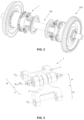
- connection (1) is fundamentally formed by a first fork (2) and a second fork (3) which are connected by means of a ball-and-socket joint.
- the first fork (2) has an inner side (21) and an outer side (22). It has two essentially parallel branches (221) on the outer side (22) which are provided with respective aligned holes for the rotatable coupling thereof to the rail axle (100).
- the coupling is performed by passing a bolt or pin through said aligned holes and corresponding holes arranged in a part integral with the rail axle (100).
- the outer side (22) of the first fork (2) is thereby jointed to the rail axle (100) about an axis (E 2a ) contained in a plane transverse to said rail axle (100). This joint is rigid as it only allows one degree of freedom.
- the inner side (21) of the first fork (2) has a central arm (211) essentially parallel to the branches (221) of the inner side (22).
- Spherical joints (4) are fixed on the side faces of the end of the central arm (211) of said inner side (21).
- each of these joints (4) comprises a spherical portion, for example, an essentially half-sphere portion.
- the second fork (3) also has an inner side (31) and an outer side (32).
- the outer side (32) of the second fork (3) is similar to that of the first fork (2), and has two essentially parallel branches (321) provided with respective aligned holes for the rotatable coupling thereof to the wheel (200). As shown in Figure 6 , the coupling is performed by means of a bolt (8) going through said holes and corresponding holes of a part integral with the wheel (200).
- the outer side of the second fork (3) is also thereby jointed to the wheel (200) about an axis (E 3a ) contained in a plane transverse to the axis of rotation of the wheel (200). This joint is also rigid as it only allows one degree of freedom.
- the inner side (31) of the second fork (3) comprises two arms (311) essentially parallel to one another and parallel to the branches (321) of the outer side (32) thereof. These arms (311) have at their end respective aligned holes, and on the inner faces of said ends they are configured to support of cups (5).
- Each cup (5) has an essentially spherical cavity which is complementary to the shape of the joints (4).
- the end of the central arm (211) of the first fork (2) can therefore be placed between the two ends of the arms (311) of the second fork (3) such that the joints (4) are housed inside the cups (5), thereby forming the ball-and-socket joint which connects the first fork (2) and the second fork (3).
- supports (6) screwed into the holes arranged at the ends of the inner side (31) of the arms (311) compress the cups (5) against the joints (4).
- These supports (6) have, fundamentally, four parts or segments: a first segment (61) having a diameter designed to be fitted into a cylindrical cavity arranged on a face of the cup (5) opposite that on which a spherical cavity is arranged; a second threaded segment (62) which is fixed, by means of thread, into the hole of the end of the corresponding arm (311); a third also threaded segment (63) for fixing, by means of thread, a lock nut (7) of the assembly; and a fourth segment (64) located at the end and having a polygonal shape, such that the support (6) can be rotated as a whole to be suitably place the cup (5).
- this connection (1) allows a certain misalignment between the first fork (2) and the second fork (3).
- Figure 5 shows such a situation where the axis (E 2b ) going through the hole of the end of the central arm (211) of the first fork (2) and the axis (E 3b ) going through the holes of the ends of the side arms (311) of the second fork (3) form an angle ⁇ . Therefore, this connection (1) allows misalignment between the wheel (200) and the rail axle (100), when required, based on the stresses to which they are subjected throughout their service life, thereby preventing breakages caused by fatigues loads.
Landscapes
- Engineering & Computer Science (AREA)
- Mechanical Engineering (AREA)
- General Engineering & Computer Science (AREA)
- Braking Arrangements (AREA)
- Vehicle Body Suspensions (AREA)
- Pivots And Pivotal Connections (AREA)
- Motor Power Transmission Devices (AREA)
Claims (3)
- Gelenkverbindung (1) zur Drehmomentübertragung in einer Schienenachse mit variablem Kaliber, umfassend:- eine erste Gabel (2), die eine Innenseite (21) und eine Außenseite (22) umfasst, wobei ein Ende der Außenseite (22) mit einem von entweder einem Rad (200) oder einer Schienenachse (100) drehbar um eine Querachse (E2a) in Bezug auf das Rad (200) oder die Schienenachse (100) verbunden werden soll;- eine zweite Gabel (3), die eine Innenseite (31) und eine Außenseite (32) aufweist, wobei ein Ende der Außenseite (32) mit dem anderen von entweder dem Rad (200) oder der Schienenachse (100) drehbar um eine Querachse (E3a) in Bezug auf das Rad (200) oder die Schienenachse (100) verbunden werden soll;wobei die Enden der Innenseiten (21, 31) der ersten und der zweiten Gabel (2, 3) mittels eines Kugelgelenks miteinander verbunden sind, und wobei das Kugelgelenk mit einem zentralen Arm (211) der Innenseite (21) der ersten Gabel (2) verbunden ist,wobei zwei zwischen zwei Schalen (5) gehaltene Kugelgelenke (4) auf gegenüberliegenden Seiten des Endes des zentralen Arms (211) der ersten Gabel (2) angeordnet sind, dadurch gekennzeichnet, dass das Kugelgelenk zwischen zwei Seitenarmen (311) der Innenseite (31) der zweiten Gabel angeordnet ist und dass die beiden Schalen (5) mittels zweier entsprechender Stützen (6) befestigt sind, die in Löcher geschraubt sind, die an den Enden der beiden Seitenarme (311) der zweiten Gabel (3) angeordnet sind.
- Verbindung (1) nach Anspruch 1, wobei jede Stütze (6) ein erstes Segment (61) zur Abstützung an der Schale (5), ein zweites, mit Gewinde versehenes Segment (62) zur Befestigung an dem Loch des Endes des Arms (311) der zweiten Gabel (3), ein drittes, mit Gewinde versehenes Segment (63) zur Aufnahme einer Kontermutter (7) und ein viertes, polygonal geformtes Segment (64) zum Einstellen der Schale (5) in ihre Position umfasst.
- Verbindung (1) nach einem der vorhergehenden Ansprüche, wobei die Verbindung zwischen den Enden der Außenseiten (22, 32) der ersten und der zweiten Gabel (2, 3) mit dem Rad (200) oder der Schienenachse (100) einen Bolzen (8) umfasst, der gemäß der Querachse (E2a, E3a) ausgerichtet ist und durch Löcher geht, die an den Enden von zwei Schenkeln (221, 321) der Außenseite (22, 32) angeordnet sind.
Applications Claiming Priority (2)
| Application Number | Priority Date | Filing Date | Title |
|---|---|---|---|
| ES202031004A ES2794248B2 (es) | 2020-10-05 | 2020-10-05 | Conexion articulada para transmision de torsor en un eje ferroviario de ancho variable |
| PCT/ES2021/070657 WO2022074266A1 (es) | 2020-10-05 | 2021-09-13 | Conexión articulada para transmisión de torsor en un eje ferroviario de ancho variable |
Publications (4)
| Publication Number | Publication Date |
|---|---|
| EP4227189A1 EP4227189A1 (de) | 2023-08-16 |
| EP4227189A4 EP4227189A4 (de) | 2024-11-13 |
| EP4227189B1 true EP4227189B1 (de) | 2025-04-16 |
| EP4227189C0 EP4227189C0 (de) | 2025-04-16 |
Family
ID=73197507
Family Applications (1)
| Application Number | Title | Priority Date | Filing Date |
|---|---|---|---|
| EP21877045.1A Active EP4227189B1 (de) | 2020-10-05 | 2021-09-13 | Gelenkverbindung zur drehmomentübertragung in einer schienenachse mit variablem kaliber |
Country Status (6)
| Country | Link |
|---|---|
| EP (1) | EP4227189B1 (de) |
| AU (1) | AU2021357853A1 (de) |
| ES (1) | ES2794248B2 (de) |
| MD (1) | MD4227189T2 (de) |
| PL (1) | PL4227189T3 (de) |
| WO (1) | WO2022074266A1 (de) |
Families Citing this family (2)
| Publication number | Priority date | Publication date | Assignee | Title |
|---|---|---|---|---|
| US11866887B2 (en) * | 2021-02-10 | 2024-01-09 | Nomadd Desert Solar Solutions Pte. Ltd. | Track-wheel based device |
| ES2979089B2 (es) * | 2024-01-25 | 2025-06-10 | E P E Administrador De Infraestructuras Ferroviarias Adif | Sistema ferroviario para cambio de ancho de via |
Family Cites Families (8)
| Publication number | Priority date | Publication date | Assignee | Title |
|---|---|---|---|---|
| GB590924A (en) * | 1945-04-09 | 1947-07-31 | Miles Aircraft Ltd | A self-aligning bearing or universal joint |
| ES338183A1 (es) * | 1967-03-17 | 1968-04-01 | Rubio Lara Bastida Camacho | Procedimiento para modificar el ancho entre ruedas en los vehiculos de ferrocarril para pasar de forma continua de un ancho de via a otro. |
| US3584918A (en) * | 1969-10-07 | 1971-06-15 | Jarva Inc | Articulated torque arm construction |
| SU393494A1 (ru) * | 1970-09-28 | 1973-08-10 | Универсальный шарнир для привода валков прокатных станов | |
| SU631702A1 (ru) * | 1977-05-16 | 1978-11-05 | Bychenko Grigorij M | Шарнир равных угловых скоростей |
| ES2428239B1 (es) * | 2013-07-11 | 2014-04-16 | Beltrán RUBIO DE HITA | Eje ferroviario con cambio automático a multiples anchos de vía |
| CN107061527A (zh) * | 2017-06-12 | 2017-08-18 | 江苏丰东热技术有限公司 | 可轴向伸缩联轴器 |
| CN208651460U (zh) * | 2018-08-01 | 2019-03-26 | 河北金菱尔特传动科技股份有限公司 | 一种可伸缩式联轴器 |
-
2020
- 2020-10-05 ES ES202031004A patent/ES2794248B2/es active Active
-
2021
- 2021-09-13 WO PCT/ES2021/070657 patent/WO2022074266A1/es not_active Ceased
- 2021-09-13 MD MDE20230815T patent/MD4227189T2/ro unknown
- 2021-09-13 EP EP21877045.1A patent/EP4227189B1/de active Active
- 2021-09-13 AU AU2021357853A patent/AU2021357853A1/en not_active Abandoned
- 2021-09-13 PL PL21877045.1T patent/PL4227189T3/pl unknown
Also Published As
| Publication number | Publication date |
|---|---|
| EP4227189A4 (de) | 2024-11-13 |
| MD4227189T2 (ro) | 2025-10-31 |
| PL4227189T3 (pl) | 2025-08-04 |
| ES2794248A1 (es) | 2020-11-17 |
| WO2022074266A1 (es) | 2022-04-14 |
| ES2794248B2 (es) | 2021-11-08 |
| EP4227189C0 (de) | 2025-04-16 |
| EP4227189A1 (de) | 2023-08-16 |
| AU2021357853A1 (en) | 2023-06-01 |
Similar Documents
| Publication | Publication Date | Title |
|---|---|---|
| EP4227189B1 (de) | Gelenkverbindung zur drehmomentübertragung in einer schienenachse mit variablem kaliber | |
| GB2522767A (en) | Coupling | |
| US20100035696A1 (en) | Driveshaft comprising a counter track joint featuring a delimited axial displacement path | |
| US6976922B2 (en) | Precision thrust bearing joint | |
| CN111219419B (zh) | 特别用于机动车辆方向盘柱的两个同心轴之间的连接装置 | |
| KR20090012137A (ko) | 가요성 디스크, 그러한 가요성 디스크가 제공된 가요성커플링, 그러한 가요성 커플링이 제공된 장착 플랜지, 및그러한 장착 플랜지가 설치된 전동 샤프트 | |
| US3279216A (en) | Misalignment coupling | |
| KR102916974B1 (ko) | 등속 커플링 | |
| CA2435398C (en) | Coupling | |
| KR102437891B1 (ko) | 연장된 클램프를 포함하는 커플링 | |
| CN219062263U (zh) | 一种新型轧钢机十字万向联轴器 | |
| EP0626915B1 (de) | Kupplungsglied für eine fahrzeuglenksäule | |
| US20250198464A1 (en) | Automotive drive shaft modular connector | |
| CA2610853A1 (en) | Improved constant-velocity joint for tiltrotor hubs | |
| JP3987008B2 (ja) | 軸継手 | |
| US7878912B2 (en) | Cardanic cross joint with insulation | |
| CN112648299A (zh) | 一种联轴器 | |
| RU2347120C1 (ru) | Шарнирно-рычажный соединительный узел | |
| CN2763626Y (zh) | 万向滚珠联轴器 | |
| RU2068382C1 (ru) | Устройство для соединения секций винтового конвейера | |
| RU1795181C (ru) | Поводково-рычажна муфта т гового привода рельсового транспортного средства | |
| KR100656840B1 (ko) | 커플링 장치 | |
| KR20230148598A (ko) | 위건드센서 리프커플링 및 이의 결합방법 | |
| IT202400003694A1 (it) | Dispositivo per la trasmissione del moto fra una macchina motrice ed un’attrezzatura o in un veicolo speciale | |
| SU1449730A2 (ru) | Поводково-рычажна муфта |
Legal Events
| Date | Code | Title | Description |
|---|---|---|---|
| STAA | Information on the status of an ep patent application or granted ep patent |
Free format text: STATUS: THE INTERNATIONAL PUBLICATION HAS BEEN MADE |
|
| PUAI | Public reference made under article 153(3) epc to a published international application that has entered the european phase |
Free format text: ORIGINAL CODE: 0009012 |
|
| STAA | Information on the status of an ep patent application or granted ep patent |
Free format text: STATUS: REQUEST FOR EXAMINATION WAS MADE |
|
| 17P | Request for examination filed |
Effective date: 20230417 |
|
| AK | Designated contracting states |
Kind code of ref document: A1 Designated state(s): AL AT BE BG CH CY CZ DE DK EE ES FI FR GB GR HR HU IE IS IT LI LT LU LV MC MK MT NL NO PL PT RO RS SE SI SK SM TR |
|
| DAX | Request for extension of the european patent (deleted) | ||
| RAV | Requested validation state of the european patent: fee paid |
Extension state: MD Effective date: 20230707 |
|
| A4 | Supplementary search report drawn up and despatched |
Effective date: 20241011 |
|
| RIC1 | Information provided on ipc code assigned before grant |
Ipc: F16C 11/06 20060101ALI20241007BHEP Ipc: F16D 3/06 20060101ALI20241007BHEP Ipc: B61F 7/00 20060101AFI20241007BHEP |
|
| GRAP | Despatch of communication of intention to grant a patent |
Free format text: ORIGINAL CODE: EPIDOSNIGR1 |
|
| STAA | Information on the status of an ep patent application or granted ep patent |
Free format text: STATUS: GRANT OF PATENT IS INTENDED |
|
| INTG | Intention to grant announced |
Effective date: 20241220 |
|
| GRAJ | Information related to disapproval of communication of intention to grant by the applicant or resumption of examination proceedings by the epo deleted |
Free format text: ORIGINAL CODE: EPIDOSDIGR1 |
|
| STAA | Information on the status of an ep patent application or granted ep patent |
Free format text: STATUS: REQUEST FOR EXAMINATION WAS MADE |
|
| GRAS | Grant fee paid |
Free format text: ORIGINAL CODE: EPIDOSNIGR3 |
|
| STAA | Information on the status of an ep patent application or granted ep patent |
Free format text: STATUS: GRANT OF PATENT IS INTENDED |
|
| GRAP | Despatch of communication of intention to grant a patent |
Free format text: ORIGINAL CODE: EPIDOSNIGR1 |
|
| GRAA | (expected) grant |
Free format text: ORIGINAL CODE: 0009210 |
|
| STAA | Information on the status of an ep patent application or granted ep patent |
Free format text: STATUS: THE PATENT HAS BEEN GRANTED |
|
| INTC | Intention to grant announced (deleted) | ||
| INTG | Intention to grant announced |
Effective date: 20250305 |
|
| AK | Designated contracting states |
Kind code of ref document: B1 Designated state(s): AL AT BE BG CH CY CZ DE DK EE ES FI FR GB GR HR HU IE IS IT LI LT LU LV MC MK MT NL NO PL PT RO RS SE SI SK SM TR |
|
| REG | Reference to a national code |
Ref country code: GB Ref legal event code: FG4D |
|
| REG | Reference to a national code |
Ref country code: CH Ref legal event code: EP |
|
| REG | Reference to a national code |
Ref country code: IE Ref legal event code: FG4D |
|
| REG | Reference to a national code |
Ref country code: DE Ref legal event code: R096 Ref document number: 602021029385 Country of ref document: DE |
|
| U01 | Request for unitary effect filed |
Effective date: 20250515 |
|
| U07 | Unitary effect registered |
Designated state(s): AT BE BG DE DK EE FI FR IT LT LU LV MT NL PT RO SE SI Effective date: 20250522 |
|
| PG25 | Lapsed in a contracting state [announced via postgrant information from national office to epo] |
Ref country code: ES Free format text: LAPSE BECAUSE OF FAILURE TO SUBMIT A TRANSLATION OF THE DESCRIPTION OR TO PAY THE FEE WITHIN THE PRESCRIBED TIME-LIMIT Effective date: 20250416 |
|
| PG25 | Lapsed in a contracting state [announced via postgrant information from national office to epo] |
Ref country code: NO Free format text: LAPSE BECAUSE OF FAILURE TO SUBMIT A TRANSLATION OF THE DESCRIPTION OR TO PAY THE FEE WITHIN THE PRESCRIBED TIME-LIMIT Effective date: 20250716 Ref country code: GR Free format text: LAPSE BECAUSE OF FAILURE TO SUBMIT A TRANSLATION OF THE DESCRIPTION OR TO PAY THE FEE WITHIN THE PRESCRIBED TIME-LIMIT Effective date: 20250717 |
|
| PGFP | Annual fee paid to national office [announced via postgrant information from national office to epo] |
Ref country code: PL Payment date: 20250821 Year of fee payment: 5 |
|
| VSFP | Annual fee paid to validation state [announced via postgrant information from national office to epo] |
Ref country code: MD Payment date: 20250825 Year of fee payment: 5 |
|
| PGFP | Annual fee paid to national office [announced via postgrant information from national office to epo] |
Ref country code: GB Payment date: 20250919 Year of fee payment: 5 |
|
| PG25 | Lapsed in a contracting state [announced via postgrant information from national office to epo] |
Ref country code: HR Free format text: LAPSE BECAUSE OF FAILURE TO SUBMIT A TRANSLATION OF THE DESCRIPTION OR TO PAY THE FEE WITHIN THE PRESCRIBED TIME-LIMIT Effective date: 20250416 |
|
| PG25 | Lapsed in a contracting state [announced via postgrant information from national office to epo] |
Ref country code: RS Free format text: LAPSE BECAUSE OF FAILURE TO SUBMIT A TRANSLATION OF THE DESCRIPTION OR TO PAY THE FEE WITHIN THE PRESCRIBED TIME-LIMIT Effective date: 20250716 |
|
| PG25 | Lapsed in a contracting state [announced via postgrant information from national office to epo] |
Ref country code: IS Free format text: LAPSE BECAUSE OF FAILURE TO SUBMIT A TRANSLATION OF THE DESCRIPTION OR TO PAY THE FEE WITHIN THE PRESCRIBED TIME-LIMIT Effective date: 20250816 |
|
| REG | Reference to a national code |
Ref country code: MD Ref legal event code: VAGR Ref document number: 4227189 Country of ref document: MD Date of ref document: 20251031 Kind code of ref document: T2 |
|
| U20 | Renewal fee for the european patent with unitary effect paid |
Year of fee payment: 5 Effective date: 20250926 |
|
| REG | Reference to a national code |
Ref country code: CH Ref legal event code: W10 Free format text: ST27 STATUS EVENT CODE: U-0-0-W10-W00 (AS PROVIDED BY THE NATIONAL OFFICE) Effective date: 20251210 |
|
| RAP2 | Party data changed (patent owner data changed or rights of a patent transferred) |
Owner name: E.P.E. ADMINISTRADOR DE INFRAESTRUCTURASFERROVIARIAS (ADIF) |
|
| U1K | Transfer of rights of the unitary patent after the registration of the unitary effect |
Owner name: E.P.E. ADMINISTRADOR DE INFRAESTRUCTURASFERROVIARIAS (ADIF); ES |
|
| PG25 | Lapsed in a contracting state [announced via postgrant information from national office to epo] |
Ref country code: SM Free format text: LAPSE BECAUSE OF FAILURE TO SUBMIT A TRANSLATION OF THE DESCRIPTION OR TO PAY THE FEE WITHIN THE PRESCRIBED TIME-LIMIT Effective date: 20250416 |
|
| PG25 | Lapsed in a contracting state [announced via postgrant information from national office to epo] |
Ref country code: CZ Free format text: LAPSE BECAUSE OF FAILURE TO SUBMIT A TRANSLATION OF THE DESCRIPTION OR TO PAY THE FEE WITHIN THE PRESCRIBED TIME-LIMIT Effective date: 20250416 |
|
| PG25 | Lapsed in a contracting state [announced via postgrant information from national office to epo] |
Ref country code: SK Free format text: LAPSE BECAUSE OF FAILURE TO SUBMIT A TRANSLATION OF THE DESCRIPTION OR TO PAY THE FEE WITHIN THE PRESCRIBED TIME-LIMIT Effective date: 20250416 |
|
| PLBE | No opposition filed within time limit |
Free format text: ORIGINAL CODE: 0009261 |
|
| STAA | Information on the status of an ep patent application or granted ep patent |
Free format text: STATUS: NO OPPOSITION FILED WITHIN TIME LIMIT |
|
| REG | Reference to a national code |
Ref country code: CH Ref legal event code: L10 Free format text: ST27 STATUS EVENT CODE: U-0-0-L10-L00 (AS PROVIDED BY THE NATIONAL OFFICE) Effective date: 20260225 |
|
| REG | Reference to a national code |
Ref country code: CH Ref legal event code: U11 Free format text: ST27 STATUS EVENT CODE: U-0-0-U10-U11 (AS PROVIDED BY THE NATIONAL OFFICE) Effective date: 20260303 |
|
| 26N | No opposition filed |
Effective date: 20260119 |
|
| PGFP | Annual fee paid to national office [announced via postgrant information from national office to epo] |
Ref country code: IE Payment date: 20260318 Year of fee payment: 5 |
|
| PGFP | Annual fee paid to national office [announced via postgrant information from national office to epo] |
Ref country code: CH Payment date: 20260303 Year of fee payment: 5 |