EP4227189A1 - Jointed connection for transmitting torque in a variable-gauge rail axle - Google Patents
Jointed connection for transmitting torque in a variable-gauge rail axle Download PDFInfo
- Publication number
- EP4227189A1 EP4227189A1 EP21877045.1A EP21877045A EP4227189A1 EP 4227189 A1 EP4227189 A1 EP 4227189A1 EP 21877045 A EP21877045 A EP 21877045A EP 4227189 A1 EP4227189 A1 EP 4227189A1
- Authority
- EP
- European Patent Office
- Prior art keywords
- fork
- wheel
- rail axle
- axle
- outer side
- Prior art date
- Legal status (The legal status is an assumption and is not a legal conclusion. Google has not performed a legal analysis and makes no representation as to the accuracy of the status listed.)
- Granted
Links
Images



Classifications
-
- B—PERFORMING OPERATIONS; TRANSPORTING
- B61—RAILWAYS
- B61F—RAIL VEHICLE SUSPENSIONS, e.g. UNDERFRAMES, BOGIES OR ARRANGEMENTS OF WHEEL AXLES; RAIL VEHICLES FOR USE ON TRACKS OF DIFFERENT WIDTH; PREVENTING DERAILING OF RAIL VEHICLES; WHEEL GUARDS, OBSTRUCTION REMOVERS OR THE LIKE FOR RAIL VEHICLES
- B61F7/00—Rail vehicles equipped for use on tracks of different width
-
- B—PERFORMING OPERATIONS; TRANSPORTING
- B60—VEHICLES IN GENERAL
- B60B—VEHICLE WHEELS; CASTORS; AXLES FOR WHEELS OR CASTORS; INCREASING WHEEL ADHESION
- B60B17/00—Wheels characterised by rail-engaging elements
-
- B—PERFORMING OPERATIONS; TRANSPORTING
- B60—VEHICLES IN GENERAL
- B60B—VEHICLE WHEELS; CASTORS; AXLES FOR WHEELS OR CASTORS; INCREASING WHEEL ADHESION
- B60B35/00—Axle units; Parts thereof ; Arrangements for lubrication of axles
- B60B35/02—Dead axles, i.e. not transmitting torque
- B60B35/10—Dead axles, i.e. not transmitting torque adjustable for varying track
-
- B—PERFORMING OPERATIONS; TRANSPORTING
- B60—VEHICLES IN GENERAL
- B60B—VEHICLE WHEELS; CASTORS; AXLES FOR WHEELS OR CASTORS; INCREASING WHEEL ADHESION
- B60B37/00—Wheel-axle combinations, e.g. wheel sets
- B60B37/04—Wheel-axle combinations, e.g. wheel sets the wheels being rigidly attached to solid axles
-
- F—MECHANICAL ENGINEERING; LIGHTING; HEATING; WEAPONS; BLASTING
- F16—ENGINEERING ELEMENTS AND UNITS; GENERAL MEASURES FOR PRODUCING AND MAINTAINING EFFECTIVE FUNCTIONING OF MACHINES OR INSTALLATIONS; THERMAL INSULATION IN GENERAL
- F16C—SHAFTS; FLEXIBLE SHAFTS; ELEMENTS OR CRANKSHAFT MECHANISMS; ROTARY BODIES OTHER THAN GEARING ELEMENTS; BEARINGS
- F16C11/00—Pivots; Pivotal connections
- F16C11/04—Pivotal connections
- F16C11/045—Pivotal connections with at least a pair of arms pivoting relatively to at least one other arm, all arms being mounted on one pin
-
- F—MECHANICAL ENGINEERING; LIGHTING; HEATING; WEAPONS; BLASTING
- F16—ENGINEERING ELEMENTS AND UNITS; GENERAL MEASURES FOR PRODUCING AND MAINTAINING EFFECTIVE FUNCTIONING OF MACHINES OR INSTALLATIONS; THERMAL INSULATION IN GENERAL
- F16C—SHAFTS; FLEXIBLE SHAFTS; ELEMENTS OR CRANKSHAFT MECHANISMS; ROTARY BODIES OTHER THAN GEARING ELEMENTS; BEARINGS
- F16C11/00—Pivots; Pivotal connections
- F16C11/04—Pivotal connections
- F16C11/06—Ball-joints; Other joints having more than one degree of angular freedom, i.e. universal joints
-
- F—MECHANICAL ENGINEERING; LIGHTING; HEATING; WEAPONS; BLASTING
- F16—ENGINEERING ELEMENTS AND UNITS; GENERAL MEASURES FOR PRODUCING AND MAINTAINING EFFECTIVE FUNCTIONING OF MACHINES OR INSTALLATIONS; THERMAL INSULATION IN GENERAL
- F16C—SHAFTS; FLEXIBLE SHAFTS; ELEMENTS OR CRANKSHAFT MECHANISMS; ROTARY BODIES OTHER THAN GEARING ELEMENTS; BEARINGS
- F16C23/00—Bearings for exclusively rotary movement adjustable for aligning or positioning
- F16C23/02—Sliding-contact bearings
- F16C23/04—Sliding-contact bearings self-adjusting
- F16C23/043—Sliding-contact bearings self-adjusting with spherical surfaces, e.g. spherical plain bearings
-
- F—MECHANICAL ENGINEERING; LIGHTING; HEATING; WEAPONS; BLASTING
- F16—ENGINEERING ELEMENTS AND UNITS; GENERAL MEASURES FOR PRODUCING AND MAINTAINING EFFECTIVE FUNCTIONING OF MACHINES OR INSTALLATIONS; THERMAL INSULATION IN GENERAL
- F16D—COUPLINGS FOR TRANSMITTING ROTATION; CLUTCHES; BRAKES
- F16D3/00—Yielding couplings, i.e. with means permitting movement between the connected parts during the drive
- F16D3/02—Yielding couplings, i.e. with means permitting movement between the connected parts during the drive adapted to specific functions
- F16D3/06—Yielding couplings, i.e. with means permitting movement between the connected parts during the drive adapted to specific functions specially adapted to allow axial displacement
-
- F—MECHANICAL ENGINEERING; LIGHTING; HEATING; WEAPONS; BLASTING
- F16—ENGINEERING ELEMENTS AND UNITS; GENERAL MEASURES FOR PRODUCING AND MAINTAINING EFFECTIVE FUNCTIONING OF MACHINES OR INSTALLATIONS; THERMAL INSULATION IN GENERAL
- F16D—COUPLINGS FOR TRANSMITTING ROTATION; CLUTCHES; BRAKES
- F16D3/00—Yielding couplings, i.e. with means permitting movement between the connected parts during the drive
- F16D3/50—Yielding couplings, i.e. with means permitting movement between the connected parts during the drive with the coupling parts connected by one or more intermediate members
- F16D3/60—Yielding couplings, i.e. with means permitting movement between the connected parts during the drive with the coupling parts connected by one or more intermediate members comprising pushing or pulling links attached to both parts
- F16D3/62—Yielding couplings, i.e. with means permitting movement between the connected parts during the drive with the coupling parts connected by one or more intermediate members comprising pushing or pulling links attached to both parts the links or their attachments being elastic
-
- B—PERFORMING OPERATIONS; TRANSPORTING
- B60—VEHICLES IN GENERAL
- B60Y—INDEXING SCHEME RELATING TO ASPECTS CROSS-CUTTING VEHICLE TECHNOLOGY
- B60Y2200/00—Type of vehicle
- B60Y2200/30—Railway vehicles
-
- F—MECHANICAL ENGINEERING; LIGHTING; HEATING; WEAPONS; BLASTING
- F16—ENGINEERING ELEMENTS AND UNITS; GENERAL MEASURES FOR PRODUCING AND MAINTAINING EFFECTIVE FUNCTIONING OF MACHINES OR INSTALLATIONS; THERMAL INSULATION IN GENERAL
- F16C—SHAFTS; FLEXIBLE SHAFTS; ELEMENTS OR CRANKSHAFT MECHANISMS; ROTARY BODIES OTHER THAN GEARING ELEMENTS; BEARINGS
- F16C2326/00—Articles relating to transporting
- F16C2326/10—Railway vehicles
-
- F—MECHANICAL ENGINEERING; LIGHTING; HEATING; WEAPONS; BLASTING
- F16—ENGINEERING ELEMENTS AND UNITS; GENERAL MEASURES FOR PRODUCING AND MAINTAINING EFFECTIVE FUNCTIONING OF MACHINES OR INSTALLATIONS; THERMAL INSULATION IN GENERAL
- F16C—SHAFTS; FLEXIBLE SHAFTS; ELEMENTS OR CRANKSHAFT MECHANISMS; ROTARY BODIES OTHER THAN GEARING ELEMENTS; BEARINGS
- F16C2361/00—Apparatus or articles in engineering in general
- F16C2361/31—Axle
-
- F—MECHANICAL ENGINEERING; LIGHTING; HEATING; WEAPONS; BLASTING
- F16—ENGINEERING ELEMENTS AND UNITS; GENERAL MEASURES FOR PRODUCING AND MAINTAINING EFFECTIVE FUNCTIONING OF MACHINES OR INSTALLATIONS; THERMAL INSULATION IN GENERAL
- F16C—SHAFTS; FLEXIBLE SHAFTS; ELEMENTS OR CRANKSHAFT MECHANISMS; ROTARY BODIES OTHER THAN GEARING ELEMENTS; BEARINGS
- F16C3/00—Shafts; Axles; Cranks; Eccentrics
- F16C3/02—Shafts; Axles
- F16C3/03—Shafts; Axles telescopic
Definitions
- the invention belongs to the railway sector, and more particularly to devices used for changing the gauge of a rail axle.
- the object of the present invention relates to a novel connection between the wheels and the axle for transmitting torque in a variable-gauge rail axle.
- Variable-gauge rail axles are designed to adapt to several different track gauges. To that end, these axles have a mechanism designed to allow the wheels to slide along the axle between two or more positions corresponding to respective track gauges. Once located in the position corresponding to the desired gauge, a fixing system locks the position of the wheels. Therefore, unlike conventional rail axles, in a variable-gauge rail axle the wheels are not fixed to the axles.
- variable-gauge rail axles Since the wheels are not fixed to the axles, the coupling mechanisms of variable-gauge rail axles must have a coupling system capable of transmitting the torque from the wheels to the axle. In fact, due to the loads supported by the rail axle, as well as the braking stresses to which it is subjected during its normal service life, a torsional stress that tends to misalign the wheels and the axle arises.
- Conventional coupling systems that do not allow the possibility of pitching between axles and wheels such as, for example splined or tongued-and-grooved coupling systems, deteriorate rapidly due to the accumulation of fatigue loads. In this context, it should be noted that a fatigue cycle occurs for each revolution of the wheel.
- Patent ES2428239B1 belonging to the inventor of the present application, describes a rail axle that can be adapted to several track gauges.
- the problem of torque transmission is solved by means of a coupling system formed by two semi-compasses that are fixed respectively to the axle and to the wheel and jointed such that they can open or close in order to adapt to the different positions of the wheel, as well as perform pitching to absorb misalignments between the wheel and axle, transmitting torque without clearances in all the positions of the wheel with respect to the axle.
- Figures 1a and 1b show sectional views of a connection (100) according to patent ES2428239B1 .
- the jointed compasses are formed by two semi-compasses (103a, 103b) having two arms at one end and a single arm at the other end, being connected on the side provided with single arm by means of joints (104a, 104b) and coupled by means of a shaft (106).
- the semi-compass (103a) houses the shaft (106) which stacks the cups (105a, 105b), the joints (104a, 104b), and the semi-compass (103b).
- semi-compass (103a) is fixed to the axle of the wheel (not shown) and semi-compass (103b) is fixed to the wheel (not shown).
- semi-compass (103a) transmits stress to the shaft (106), which transmits the torque by contact to the cup (105a), which also transmits same by pressure to the joint (104a) and to semi-compass (103b), which finally transmits same to the wheel.
- This is the optimal route for torque transmission, since torque is always transmitted by pressure between contacting surfaces.
- semi-compass (103a) transmits stress to the shaft (106) through the thread, and the latter transmits same by traction to the cup of the farthest joint which transmits the stress by pressure between surfaces to the cup (105b) and from the joint (104b) to semi-compass (103b).
- the route followed involves causing the shaft (106) coupling the semi-compasses (103a, 103b) to work under traction and also bending due to the friction between the joint and the cup, accumulating a stress cycle at each turn. Since the shaft coupling the semi-compasses is the weakest part of the system, the accumulation of fatigue loads could lead to shaft breakage and it constitutes a problem for systems that require greater stress transmission, like in the case of drive shafts or shafts with disc brakes incorporated in the central area of the shaft.
- the present invention describes a jointed connection for coupling the axle and the wheel in a variable-gauge rail axle which solves the preceding problems.
- the main concept consists of the use of a spherical joint which connects two forks which are in turn connected respectively to the wheel and to the axle. This spherical joint allows the misalignment between the two forks, and therefore also between the wheel and the rail axle.
- connection of the present invention fundamentally comprises the following elements:
- the end of the outer side is connected to one of either the wheel or the rail axle rotatably about a transverse axis with respect to said wheel or axle.
- the connection between the end of the outer side of the first fork to the wheel or the axle comprises a bolt oriented according to the transverse axis going through holes arranged at the ends of two branches of said peripheral side.
- the second fork has an inner side and an outer side.
- connection between the end of the outer side of the second fork to the wheel or the axle preferably comprises a bolt oriented according to the transverse axis going through holes arranged at the ends of two branches of said peripheral side.
- the ball-and-socket joint connects the ends of the inner sides of the first and second forks to one another. In this way, an additional degree of freedom is provided to the coupling between both forks allowing misalignments between the wheel and the rail axle, thereby reducing the wear that occurs throughout the service life of said rail axle.
- the ball-and-socket joint can be implemented in different manners as long as it allows said misalignments.
- the ball-and-socket joint comprises a central arm of the inner side of the first fork arranged between two side arms of the inner side of the second fork.
- opposite faces of the end of the central arm of the first fork comprise two spherical joints retained between two cups fixed by means of two corresponding supports screwed into holes arranged at the ends of the two side arms of the second fork.
- the spherical joints fixed to the faces of the end of the central arm of the first fork are housed inside spherical cavities of the cups which are in turn fixed to the side arms of the second fork. In this way, a misalignment between the axes of rotation of the first and the second forks, respectively, and therefore also between the axles of the wheel and the rail axle, can occur.
- each support comprises a first segment for support against the cup, a second threaded segment for the fixing thereof to the hole of the end of the arm of the second fork, a third threaded segment for receiving a lock nut, and a fourth polygonal-shaped segment for setting the cup in its position.
- connection (1) An example of the connection (1) according to the present invention is described below in reference to the attached figures in which the different parts making up same can be seen.
- connection (1) is fundamentally formed by a first fork (2) and a second fork (3) which are connected by means of a ball-and-socket joint.
- the first fork (2) has an inner side (21) and an outer side (22). It has two essentially parallel branches (221) on the outer side (22) which are provided with respective aligned holes for the rotatable coupling thereof to the rail axle (100).
- the coupling is performed by passing a bolt or pin through said aligned holes and corresponding holes arranged in a part integral with the rail axle (100).
- the outer side (22) of the first fork (2) is thereby jointed to the rail axle (100) about an axis (E 2a ) contained in a plane transverse to said rail axle (100). This joint is rigid as it only allows one degree of freedom.
- the inner side (21) of the first fork (2) has a central arm (211) essentially parallel to the branches (221) of the inner side (22).
- Spherical joints (4) are fixed on the side faces of the end of the central arm (211) of said inner side (21).
- each of these joints (4) comprises a spherical portion, for example, an essentially half-sphere portion.
- the second fork (3) also has an inner side (31) and an outer side (32).
- the outer side (32) of the second fork (3) is similar to that of the first fork (2), and has two essentially parallel branches (321) provided with respective aligned holes for the rotatable coupling thereof to the wheel (200). As shown in Figure 6 , the coupling is performed by means of a bolt (8) going through said holes and corresponding holes of a part integral with the wheel (200).
- the outer side of the second fork (3) is also thereby jointed to the wheel (200) about an axis (E 3a ) contained in a plane transverse to the axis of rotation of the wheel (200). This joint is also rigid as it only allows one degree of freedom.
- the inner side (31) of the second fork (3) comprises two arms (311) essentially parallel to one another and parallel to the branches (321) of the outer side (32) thereof. These arms (311) have at their end respective aligned holes, and on the inner faces of said ends they are configured to support of cups (5).
- Each cup (5) has an essentially spherical cavity which is complementary to the shape of the joints (4).
- the end of the central arm (211) of the first fork (2) can therefore be placed between the two ends of the arms (311) of the second fork (3) such that the joints (4) are housed inside the cups (5), thereby forming the ball-and-socket joint which connects the first fork (2) and the second fork (3).
- supports (6) screwed into the holes arranged at the ends of the inner side (31) of the arms (311) compress the cups (5) against the joints (4).
- These supports (6) have, fundamentally, four parts or segments: a first segment (61) having a diameter designed to be fitted into a cylindrical cavity arranged on a face of the cup (5) opposite that on which a spherical cavity is arranged; a second threaded segment (62) which is fixed, by means of thread, into the hole of the end of the corresponding arm (311); a third also threaded segment (63) for fixing, by means of thread, a lock nut (7) of the assembly; and a fourth segment (64) located at the end and having a polygonal shape, such that the support (6) can be rotated as a whole to be suitably place the cup (5).
- this connection (1) allows a certain misalignment between the first fork (2) and the second fork (3).
- Figure 5 shows such a situation where the axis (E 2b ) going through the hole of the end of the central arm (211) of the first fork (2) and the axis (E 3b ) going through the holes of the ends of the side arms (311) of the second fork (3) form an angle ⁇ . Therefore, this connection (1) allows misalignment between the wheel (200) and the rail axle (100), when required, based on the stresses to which they are subjected throughout their service life, thereby preventing breakages caused by fatigues loads.
Landscapes
- Engineering & Computer Science (AREA)
- General Engineering & Computer Science (AREA)
- Mechanical Engineering (AREA)
- Braking Arrangements (AREA)
- Vehicle Body Suspensions (AREA)
- Pivots And Pivotal Connections (AREA)
- Motor Power Transmission Devices (AREA)
Abstract
Description
- Generally, the invention belongs to the railway sector, and more particularly to devices used for changing the gauge of a rail axle.
- The object of the present invention relates to a novel connection between the wheels and the axle for transmitting torque in a variable-gauge rail axle.
- Variable-gauge rail axles are designed to adapt to several different track gauges. To that end, these axles have a mechanism designed to allow the wheels to slide along the axle between two or more positions corresponding to respective track gauges. Once located in the position corresponding to the desired gauge, a fixing system locks the position of the wheels. Therefore, unlike conventional rail axles, in a variable-gauge rail axle the wheels are not fixed to the axles.
- Since the wheels are not fixed to the axles, the coupling mechanisms of variable-gauge rail axles must have a coupling system capable of transmitting the torque from the wheels to the axle. In fact, due to the loads supported by the rail axle, as well as the braking stresses to which it is subjected during its normal service life, a torsional stress that tends to misalign the wheels and the axle arises. Conventional coupling systems that do not allow the possibility of pitching between axles and wheels such as, for example splined or tongued-and-grooved coupling systems, deteriorate rapidly due to the accumulation of fatigue loads. In this context, it should be noted that a fatigue cycle occurs for each revolution of the wheel. Taking into account that a rail axle has a service life of several million kilometers, the number of fatigue cycles to which the axle is subjected can exceed 109. Therefore, even if the loads in each cycle are small, the wheel-axle coupling system can break due to fatigue. In short, the problem of torque transmission in variable-gauge rail axles is a key aspect for axle viability.
- Patent
ES2428239B1 -
Figures 1a and 1b show sectional views of a connection (100) according to patentES2428239B1 - Supposedly, semi-compass (103a) is fixed to the axle of the wheel (not shown) and semi-compass (103b) is fixed to the wheel (not shown). When torque is transmitted from semi-compass (103a) to semi-compass (103b), semi-compass (103a) transmits stress to the shaft (106), which transmits the torque by contact to the cup (105a), which also transmits same by pressure to the joint (104a) and to semi-compass (103b), which finally transmits same to the wheel. This is the optimal route for torque transmission, since torque is always transmitted by pressure between contacting surfaces.
- However, in the case where torque is transmitted in the opposite direction with semi-compass (103a) driving semi-compass (103b) during the movement thereof, semi-compass (103a) transmits stress to the shaft (106) through the thread, and the latter transmits same by traction to the cup of the farthest joint which transmits the stress by pressure between surfaces to the cup (105b) and from the joint (104b) to semi-compass (103b).
- In this second case, the route followed involves causing the shaft (106) coupling the semi-compasses (103a, 103b) to work under traction and also bending due to the friction between the joint and the cup, accumulating a stress cycle at each turn. Since the shaft coupling the semi-compasses is the weakest part of the system, the accumulation of fatigue loads could lead to shaft breakage and it constitutes a problem for systems that require greater stress transmission, like in the case of drive shafts or shafts with disc brakes incorporated in the central area of the shaft.
- On the other hand, as shown in
Figure 1b , there is the drawback that the shaft (106) is fixed to the cups (105a, 105b) and goes through the hole of the joints (104a, 104b). As a result thereof, the pitching movement between both semi-compasses (103a, 103b) is limited by the difference in diameters between the shaft (106) and the hole of the joint (104a, 104b), thus imposing a mechanical limit that restricts movement and forces greater precision in assembly. Furthermore, shaft breakage could occur if the shaft (106) comes into contact with the joint (104a, 104b) in the areas marked inFigure 1b . - Breakage of the coupling joint of a single semi-compass assembly would not be catastrophic, since two or more such coupling systems are assembled typically. However, it would cause an overload on the remaining coupling systems which, under very adverse conditions, could lead to breakage of the remaining coupling systems. This risk increases if the axle is a drive axle, since in this case, in addition to transmitting torque due to self-centering on the track, it must also transmit traction and braking forces.
- In short, there is still a need in the art of a wheel-rail axle coupling system which solves the preceding problems.
- The present invention describes a jointed connection for coupling the axle and the wheel in a variable-gauge rail axle which solves the preceding problems. The main concept consists of the use of a spherical joint which connects two forks which are in turn connected respectively to the wheel and to the axle. This spherical joint allows the misalignment between the two forks, and therefore also between the wheel and the rail axle.
- More specifically, the connection of the present invention fundamentally comprises the following elements:
- a) First fork
- This is a fork comprising an inner side and an outer side.
- The end of the outer side is connected to one of either the wheel or the rail axle rotatably about a transverse axis with respect to said wheel or axle. For example, in a particularly preferred embodiment, the connection between the end of the outer side of the first fork to the wheel or the axle comprises a bolt oriented according to the transverse axis going through holes arranged at the ends of two branches of said peripheral side.
- The second fork has an inner side and an outer side.
- The end of the outer side is connected to the other of either the wheel or the rail axle rotatably about a transverse axis with respect to said wheel or axle. Like in the first fork, in this case, the connection between the end of the outer side of the second fork to the wheel or the axle preferably comprises a bolt oriented according to the transverse axis going through holes arranged at the ends of two branches of said peripheral side.
- The ball-and-socket joint connects the ends of the inner sides of the first and second forks to one another. In this way, an additional degree of freedom is provided to the coupling between both forks allowing misalignments between the wheel and the rail axle, thereby reducing the wear that occurs throughout the service life of said rail axle.
- In principle, the ball-and-socket joint can be implemented in different manners as long as it allows said misalignments. Specifically, according to a particularly preferred embodiment of the invention, the ball-and-socket joint comprises a central arm of the inner side of the first fork arranged between two side arms of the inner side of the second fork. Furthermore, opposite faces of the end of the central arm of the first fork comprise two spherical joints retained between two cups fixed by means of two corresponding supports screwed into holes arranged at the ends of the two side arms of the second fork. In other words, the spherical joints fixed to the faces of the end of the central arm of the first fork are housed inside spherical cavities of the cups which are in turn fixed to the side arms of the second fork. In this way, a misalignment between the axes of rotation of the first and the second forks, respectively, and therefore also between the axles of the wheel and the rail axle, can occur.
- According to a particularly preferred embodiment of the invention, each support comprises a first segment for support against the cup, a second threaded segment for the fixing thereof to the hole of the end of the arm of the second fork, a third threaded segment for receiving a lock nut, and a fourth polygonal-shaped segment for setting the cup in its position. These supports allow a simple assembly and disassembly of the ball-and-socket joint.
-
-
Figures 1a and 1b show a sectional view of a connection according to the prior art. -
Figure 2 shows a perspective view of a rail axle with the wheels coupled and provided with a connection according to the present invention. -
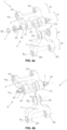
Figure 3 shows a perspective view of a connection according to the present invention. -
Figures 4a and 4b show respective perspective views of a connection according to the present invention in a partially disassembled state. -
Figure 5 shows a perspective view of a connection according to the present invention in which the misalignment between both forks can be seen. -
Figure 6 shows a perspective view showing the coupling between the connection of the invention and the wheel of the rail axle. - An example of the connection (1) according to the present invention is described below in reference to the attached figures in which the different parts making up same can be seen.
- The connection (1) is fundamentally formed by a first fork (2) and a second fork (3) which are connected by means of a ball-and-socket joint.
- The first fork (2) has an inner side (21) and an outer side (22). It has two essentially parallel branches (221) on the outer side (22) which are provided with respective aligned holes for the rotatable coupling thereof to the rail axle (100). As can be clearly seen in
Figure 6 , the coupling is performed by passing a bolt or pin through said aligned holes and corresponding holes arranged in a part integral with the rail axle (100). The outer side (22) of the first fork (2) is thereby jointed to the rail axle (100) about an axis (E2a) contained in a plane transverse to said rail axle (100). This joint is rigid as it only allows one degree of freedom. - On the other hand, the inner side (21) of the first fork (2) has a central arm (211) essentially parallel to the branches (221) of the inner side (22). Spherical joints (4) are fixed on the side faces of the end of the central arm (211) of said inner side (21). Specifically, each of these joints (4) comprises a spherical portion, for example, an essentially half-sphere portion.
- The second fork (3) also has an inner side (31) and an outer side (32). The outer side (32) of the second fork (3) is similar to that of the first fork (2), and has two essentially parallel branches (321) provided with respective aligned holes for the rotatable coupling thereof to the wheel (200). As shown in
Figure 6 , the coupling is performed by means of a bolt (8) going through said holes and corresponding holes of a part integral with the wheel (200). The outer side of the second fork (3) is also thereby jointed to the wheel (200) about an axis (E3a) contained in a plane transverse to the axis of rotation of the wheel (200). This joint is also rigid as it only allows one degree of freedom. - The inner side (31) of the second fork (3) comprises two arms (311) essentially parallel to one another and parallel to the branches (321) of the outer side (32) thereof. These arms (311) have at their end respective aligned holes, and on the inner faces of said ends they are configured to support of cups (5). Each cup (5) has an essentially spherical cavity which is complementary to the shape of the joints (4).
- The end of the central arm (211) of the first fork (2) can therefore be placed between the two ends of the arms (311) of the second fork (3) such that the joints (4) are housed inside the cups (5), thereby forming the ball-and-socket joint which connects the first fork (2) and the second fork (3). To complete the joint, supports (6) screwed into the holes arranged at the ends of the inner side (31) of the arms (311) compress the cups (5) against the joints (4). These supports (6) have, fundamentally, four parts or segments: a first segment (61) having a diameter designed to be fitted into a cylindrical cavity arranged on a face of the cup (5) opposite that on which a spherical cavity is arranged; a second threaded segment (62) which is fixed, by means of thread, into the hole of the end of the corresponding arm (311); a third also threaded segment (63) for fixing, by means of thread, a lock nut (7) of the assembly; and a fourth segment (64) located at the end and having a polygonal shape, such that the support (6) can be rotated as a whole to be suitably place the cup (5).
- As a result of this configuration, this connection (1) allows a certain misalignment between the first fork (2) and the second fork (3).
Figure 5 shows such a situation where the axis (E2b) going through the hole of the end of the central arm (211) of the first fork (2) and the axis (E3b) going through the holes of the ends of the side arms (311) of the second fork (3) form an angle α. Therefore, this connection (1) allows misalignment between the wheel (200) and the rail axle (100), when required, based on the stresses to which they are subjected throughout their service life, thereby preventing breakages caused by fatigues loads.
Claims (3)
- A jointed connection (1) for transmitting torque in a variable-gauge rail axle, comprising:- a first fork (2) comprising an inner side (21) and an outer side (22), wherein an end of the outer side (22) is connected to one of either a wheel (200) or a rail axle (100) rotatably about a transverse axis (E2a) with respect to said wheel (200) or rail axle (100);- a second fork (3) having an inner side (31) and an outer side (32), wherein an end of the outer side (32) is connected to the other of either the wheel (200) or the rail axle (100) rotatably about a transverse axis (E3a) with respect to said wheel (200) or rail axle (100);characterized in that the ends of the inner sides (21, 31) of the first and second forks (2, 3) are connected to one another by means of a ball-and-socket joint,and wherein the ball-and-socket joint comprises a central arm (211) of the inner side (21) of the first fork (2) arranged between two side arms (311) of the inner side (31) of the second fork (3), wherein opposite faces of the end of the central arm (211) of the first fork (2) comprise two spherical joints (4) retained between two cups (5) fixed by means of two corresponding supports (6) screwed into holes arranged at the ends of the two side arms (311) of the second fork (3).
- The connection (1) according to claim 1, wherein each support (6) comprises a first segment (61) for support against the cup (5), a second threaded segment (62) for the fixing thereof to the hole of the end of the arm (311) of the second fork (3), a third threaded segment (63) for receiving a lock nut (7), and a fourth polygonal-shaped segment (64) for setting the cup (5) in its position.
- The connection (1) according to any of the preceding claims, wherein the connection between the ends of the outer sides (22, 32) of the first and the second forks (2, 3) to the wheel (200) or the rail axle (100) comprises a bolt (8) oriented according to the transverse axis (E2a, E3a) going through holes arranged at the ends of two branches (221, 321) of said outer side (22, 32).
Applications Claiming Priority (2)
| Application Number | Priority Date | Filing Date | Title |
|---|---|---|---|
| ES202031004A ES2794248B2 (en) | 2020-10-05 | 2020-10-05 | ARTICULATED CONNECTION FOR TORSOR TRANSMISSION ON A VARIABLE WIDTH RAILWAY AXLE |
| PCT/ES2021/070657 WO2022074266A1 (en) | 2020-10-05 | 2021-09-13 | Jointed connection for transmitting torque in a variable-gauge rail axle |
Publications (4)
| Publication Number | Publication Date |
|---|---|
| EP4227189A1 true EP4227189A1 (en) | 2023-08-16 |
| EP4227189A4 EP4227189A4 (en) | 2024-11-13 |
| EP4227189B1 EP4227189B1 (en) | 2025-04-16 |
| EP4227189C0 EP4227189C0 (en) | 2025-04-16 |
Family
ID=73197507
Family Applications (1)
| Application Number | Title | Priority Date | Filing Date |
|---|---|---|---|
| EP21877045.1A Active EP4227189B1 (en) | 2020-10-05 | 2021-09-13 | Jointed connection for transmitting torque in a variable-gauge rail axle |
Country Status (6)
| Country | Link |
|---|---|
| EP (1) | EP4227189B1 (en) |
| AU (1) | AU2021357853A1 (en) |
| ES (1) | ES2794248B2 (en) |
| MD (1) | MD4227189T2 (en) |
| PL (1) | PL4227189T3 (en) |
| WO (1) | WO2022074266A1 (en) |
Families Citing this family (2)
| Publication number | Priority date | Publication date | Assignee | Title |
|---|---|---|---|---|
| US11866887B2 (en) * | 2021-02-10 | 2024-01-09 | Nomadd Desert Solar Solutions Pte. Ltd. | Track-wheel based device |
| ES2979089B2 (en) * | 2024-01-25 | 2025-06-10 | E P E Administrador De Infraestructuras Ferroviarias Adif | RAILWAY SYSTEM FOR CHANGE OF TRACK GAUGE |
Family Cites Families (8)
| Publication number | Priority date | Publication date | Assignee | Title |
|---|---|---|---|---|
| GB590924A (en) * | 1945-04-09 | 1947-07-31 | Miles Aircraft Ltd | A self-aligning bearing or universal joint |
| ES338183A1 (en) * | 1967-03-17 | 1968-04-01 | Rubio Lara Bastida Camacho | Procedure to modify the width between wheels in the railroad vehicles to pass continuously from one width from one to the other. (Machine-translation by Google Translate, not legally binding) |
| US3584918A (en) * | 1969-10-07 | 1971-06-15 | Jarva Inc | Articulated torque arm construction |
| SU393494A1 (en) * | 1970-09-28 | 1973-08-10 | UNIVERSAL HINGE FOR DRIVING ROLL MILLS DRIVES | |
| SU631702A1 (en) * | 1977-05-16 | 1978-11-05 | Bychenko Grigorij M | Equal angular velocity fork joint |
| ES2428239B1 (en) * | 2013-07-11 | 2014-04-16 | Beltrán RUBIO DE HITA | Railway axle with automatic transmission to multiple track widths |
| CN107061527A (en) * | 2017-06-12 | 2017-08-18 | 江苏丰东热技术有限公司 | Can axial stretching shaft coupling |
| CN208651460U (en) * | 2018-08-01 | 2019-03-26 | 河北金菱尔特传动科技股份有限公司 | A kind of extension type shaft coupling |
-
2020
- 2020-10-05 ES ES202031004A patent/ES2794248B2/en active Active
-
2021
- 2021-09-13 AU AU2021357853A patent/AU2021357853A1/en not_active Abandoned
- 2021-09-13 EP EP21877045.1A patent/EP4227189B1/en active Active
- 2021-09-13 MD MDE20230815T patent/MD4227189T2/en unknown
- 2021-09-13 WO PCT/ES2021/070657 patent/WO2022074266A1/en not_active Ceased
- 2021-09-13 PL PL21877045.1T patent/PL4227189T3/en unknown
Also Published As
| Publication number | Publication date |
|---|---|
| EP4227189B1 (en) | 2025-04-16 |
| EP4227189C0 (en) | 2025-04-16 |
| EP4227189A4 (en) | 2024-11-13 |
| ES2794248B2 (en) | 2021-11-08 |
| AU2021357853A1 (en) | 2023-06-01 |
| MD4227189T2 (en) | 2025-10-31 |
| ES2794248A1 (en) | 2020-11-17 |
| WO2022074266A1 (en) | 2022-04-14 |
| PL4227189T3 (en) | 2025-08-04 |
Similar Documents
| Publication | Publication Date | Title |
|---|---|---|
| EP4227189B1 (en) | Jointed connection for transmitting torque in a variable-gauge rail axle | |
| US4439168A (en) | Coupling between two rotary shafts | |
| JPS6141039A (en) | Differential gear device for automobile | |
| GB2522767A (en) | Coupling | |
| US6976922B2 (en) | Precision thrust bearing joint | |
| KR20090012137A (en) | Flexible discs, flexible couplings provided with such flexible discs, mounting flanges provided with such flexible couplings, and motorized shafts with such mounting flanges installed | |
| KR102916974B1 (en) | constant velocity coupling | |
| CN100417830C (en) | Couplings that accommodate large angular and axial displacements | |
| CA2435398C (en) | Coupling | |
| KR200353896Y1 (en) | Coupling apparatus | |
| US4501571A (en) | Large operating angle constant-speed joint | |
| KR20220039063A (en) | A coupling including extended clamp | |
| CN219062263U (en) | Novel cross universal coupling of rolling mill | |
| EP0626915B1 (en) | Steering lower shaft assembly coupling | |
| JP3987008B2 (en) | Shaft coupling | |
| SU1200017A1 (en) | Arrangement for shaft coupling | |
| US20250198464A1 (en) | Automotive drive shaft modular connector | |
| CN112648299A (en) | Shaft coupling | |
| RU2347120C1 (en) | Hinged-lever linkage | |
| RU2068382C1 (en) | Screw conveyor section connecting device | |
| CN107327509B (en) | Universal coupling | |
| CN2763626Y (en) | Universal rolling ball coupling | |
| RU1795181C (en) | Carrier-lever coupling of power drive of railway vehicle | |
| SU1449730A2 (en) | Driver-linkage clutch | |
| KR20230148598A (en) | Wigund Sensor Leaf Coupling and Its Combination Method |
Legal Events
| Date | Code | Title | Description |
|---|---|---|---|
| STAA | Information on the status of an ep patent application or granted ep patent |
Free format text: STATUS: THE INTERNATIONAL PUBLICATION HAS BEEN MADE |
|
| PUAI | Public reference made under article 153(3) epc to a published international application that has entered the european phase |
Free format text: ORIGINAL CODE: 0009012 |
|
| STAA | Information on the status of an ep patent application or granted ep patent |
Free format text: STATUS: REQUEST FOR EXAMINATION WAS MADE |
|
| 17P | Request for examination filed |
Effective date: 20230417 |
|
| AK | Designated contracting states |
Kind code of ref document: A1 Designated state(s): AL AT BE BG CH CY CZ DE DK EE ES FI FR GB GR HR HU IE IS IT LI LT LU LV MC MK MT NL NO PL PT RO RS SE SI SK SM TR |
|
| DAX | Request for extension of the european patent (deleted) | ||
| RAV | Requested validation state of the european patent: fee paid |
Extension state: MD Effective date: 20230707 |
|
| A4 | Supplementary search report drawn up and despatched |
Effective date: 20241011 |
|
| RIC1 | Information provided on ipc code assigned before grant |
Ipc: F16C 11/06 20060101ALI20241007BHEP Ipc: F16D 3/06 20060101ALI20241007BHEP Ipc: B61F 7/00 20060101AFI20241007BHEP |
|
| GRAP | Despatch of communication of intention to grant a patent |
Free format text: ORIGINAL CODE: EPIDOSNIGR1 |
|
| STAA | Information on the status of an ep patent application or granted ep patent |
Free format text: STATUS: GRANT OF PATENT IS INTENDED |
|
| INTG | Intention to grant announced |
Effective date: 20241220 |
|
| GRAJ | Information related to disapproval of communication of intention to grant by the applicant or resumption of examination proceedings by the epo deleted |
Free format text: ORIGINAL CODE: EPIDOSDIGR1 |
|
| STAA | Information on the status of an ep patent application or granted ep patent |
Free format text: STATUS: REQUEST FOR EXAMINATION WAS MADE |
|
| GRAS | Grant fee paid |
Free format text: ORIGINAL CODE: EPIDOSNIGR3 |
|
| STAA | Information on the status of an ep patent application or granted ep patent |
Free format text: STATUS: GRANT OF PATENT IS INTENDED |
|
| GRAP | Despatch of communication of intention to grant a patent |
Free format text: ORIGINAL CODE: EPIDOSNIGR1 |
|
| GRAA | (expected) grant |
Free format text: ORIGINAL CODE: 0009210 |
|
| STAA | Information on the status of an ep patent application or granted ep patent |
Free format text: STATUS: THE PATENT HAS BEEN GRANTED |
|
| INTC | Intention to grant announced (deleted) | ||
| INTG | Intention to grant announced |
Effective date: 20250305 |
|
| AK | Designated contracting states |
Kind code of ref document: B1 Designated state(s): AL AT BE BG CH CY CZ DE DK EE ES FI FR GB GR HR HU IE IS IT LI LT LU LV MC MK MT NL NO PL PT RO RS SE SI SK SM TR |
|
| REG | Reference to a national code |
Ref country code: GB Ref legal event code: FG4D |
|
| REG | Reference to a national code |
Ref country code: CH Ref legal event code: EP |
|
| REG | Reference to a national code |
Ref country code: IE Ref legal event code: FG4D |
|
| REG | Reference to a national code |
Ref country code: DE Ref legal event code: R096 Ref document number: 602021029385 Country of ref document: DE |
|
| U01 | Request for unitary effect filed |
Effective date: 20250515 |
|
| U07 | Unitary effect registered |
Designated state(s): AT BE BG DE DK EE FI FR IT LT LU LV MT NL PT RO SE SI Effective date: 20250522 |
|
| PG25 | Lapsed in a contracting state [announced via postgrant information from national office to epo] |
Ref country code: ES Free format text: LAPSE BECAUSE OF FAILURE TO SUBMIT A TRANSLATION OF THE DESCRIPTION OR TO PAY THE FEE WITHIN THE PRESCRIBED TIME-LIMIT Effective date: 20250416 |
|
| PG25 | Lapsed in a contracting state [announced via postgrant information from national office to epo] |
Ref country code: NO Free format text: LAPSE BECAUSE OF FAILURE TO SUBMIT A TRANSLATION OF THE DESCRIPTION OR TO PAY THE FEE WITHIN THE PRESCRIBED TIME-LIMIT Effective date: 20250716 Ref country code: GR Free format text: LAPSE BECAUSE OF FAILURE TO SUBMIT A TRANSLATION OF THE DESCRIPTION OR TO PAY THE FEE WITHIN THE PRESCRIBED TIME-LIMIT Effective date: 20250717 |
|
| PGFP | Annual fee paid to national office [announced via postgrant information from national office to epo] |
Ref country code: PL Payment date: 20250821 Year of fee payment: 5 |
|
| VSFP | Annual fee paid to validation state [announced via postgrant information from national office to epo] |
Ref country code: MD Payment date: 20250825 Year of fee payment: 5 |
|
| PGFP | Annual fee paid to national office [announced via postgrant information from national office to epo] |
Ref country code: GB Payment date: 20250919 Year of fee payment: 5 |
|
| PG25 | Lapsed in a contracting state [announced via postgrant information from national office to epo] |
Ref country code: HR Free format text: LAPSE BECAUSE OF FAILURE TO SUBMIT A TRANSLATION OF THE DESCRIPTION OR TO PAY THE FEE WITHIN THE PRESCRIBED TIME-LIMIT Effective date: 20250416 |
|
| PG25 | Lapsed in a contracting state [announced via postgrant information from national office to epo] |
Ref country code: RS Free format text: LAPSE BECAUSE OF FAILURE TO SUBMIT A TRANSLATION OF THE DESCRIPTION OR TO PAY THE FEE WITHIN THE PRESCRIBED TIME-LIMIT Effective date: 20250716 |
|
| PG25 | Lapsed in a contracting state [announced via postgrant information from national office to epo] |
Ref country code: IS Free format text: LAPSE BECAUSE OF FAILURE TO SUBMIT A TRANSLATION OF THE DESCRIPTION OR TO PAY THE FEE WITHIN THE PRESCRIBED TIME-LIMIT Effective date: 20250816 |
|
| REG | Reference to a national code |
Ref country code: MD Ref legal event code: VAGR Ref document number: 4227189 Country of ref document: MD Date of ref document: 20251031 Kind code of ref document: T2 |
|
| U20 | Renewal fee for the european patent with unitary effect paid |
Year of fee payment: 5 Effective date: 20250926 |
|
| REG | Reference to a national code |
Ref country code: CH Ref legal event code: W10 Free format text: ST27 STATUS EVENT CODE: U-0-0-W10-W00 (AS PROVIDED BY THE NATIONAL OFFICE) Effective date: 20251210 |
|
| RAP2 | Party data changed (patent owner data changed or rights of a patent transferred) |
Owner name: E.P.E. ADMINISTRADOR DE INFRAESTRUCTURASFERROVIARIAS (ADIF) |
|
| U1K | Transfer of rights of the unitary patent after the registration of the unitary effect |
Owner name: E.P.E. ADMINISTRADOR DE INFRAESTRUCTURASFERROVIARIAS (ADIF); ES |
|
| PG25 | Lapsed in a contracting state [announced via postgrant information from national office to epo] |
Ref country code: SM Free format text: LAPSE BECAUSE OF FAILURE TO SUBMIT A TRANSLATION OF THE DESCRIPTION OR TO PAY THE FEE WITHIN THE PRESCRIBED TIME-LIMIT Effective date: 20250416 |
|
| PG25 | Lapsed in a contracting state [announced via postgrant information from national office to epo] |
Ref country code: CZ Free format text: LAPSE BECAUSE OF FAILURE TO SUBMIT A TRANSLATION OF THE DESCRIPTION OR TO PAY THE FEE WITHIN THE PRESCRIBED TIME-LIMIT Effective date: 20250416 |
|
| PG25 | Lapsed in a contracting state [announced via postgrant information from national office to epo] |
Ref country code: SK Free format text: LAPSE BECAUSE OF FAILURE TO SUBMIT A TRANSLATION OF THE DESCRIPTION OR TO PAY THE FEE WITHIN THE PRESCRIBED TIME-LIMIT Effective date: 20250416 |
|
| PLBE | No opposition filed within time limit |
Free format text: ORIGINAL CODE: 0009261 |
|
| STAA | Information on the status of an ep patent application or granted ep patent |
Free format text: STATUS: NO OPPOSITION FILED WITHIN TIME LIMIT |
|
| REG | Reference to a national code |
Ref country code: CH Ref legal event code: L10 Free format text: ST27 STATUS EVENT CODE: U-0-0-L10-L00 (AS PROVIDED BY THE NATIONAL OFFICE) Effective date: 20260225 |
|
| REG | Reference to a national code |
Ref country code: CH Ref legal event code: U11 Free format text: ST27 STATUS EVENT CODE: U-0-0-U10-U11 (AS PROVIDED BY THE NATIONAL OFFICE) Effective date: 20260303 |
|
| 26N | No opposition filed |
Effective date: 20260119 |
|
| PGFP | Annual fee paid to national office [announced via postgrant information from national office to epo] |
Ref country code: IE Payment date: 20260318 Year of fee payment: 5 |
|
| PGFP | Annual fee paid to national office [announced via postgrant information from national office to epo] |
Ref country code: CH Payment date: 20260303 Year of fee payment: 5 |
|
| PG25 | Lapsed in a contracting state [announced via postgrant information from national office to epo] |
Ref country code: MC Free format text: LAPSE BECAUSE OF FAILURE TO SUBMIT A TRANSLATION OF THE DESCRIPTION OR TO PAY THE FEE WITHIN THE PRESCRIBED TIME-LIMIT Effective date: 20250416 |