EP4225594B1 - Fahrzeugluftreifen mit umfangsrille - Google Patents
Fahrzeugluftreifen mit umfangsrille Download PDFInfo
- Publication number
- EP4225594B1 EP4225594B1 EP21798279.2A EP21798279A EP4225594B1 EP 4225594 B1 EP4225594 B1 EP 4225594B1 EP 21798279 A EP21798279 A EP 21798279A EP 4225594 B1 EP4225594 B1 EP 4225594B1
- Authority
- EP
- European Patent Office
- Prior art keywords
- groove
- pneumatic vehicle
- circumferential
- radial direction
- cross
- Prior art date
- Legal status (The legal status is an assumption and is not a legal conclusion. Google has not performed a legal analysis and makes no representation as to the accuracy of the status listed.)
- Active
Links
Images



Classifications
-
- B—PERFORMING OPERATIONS; TRANSPORTING
- B60—VEHICLES IN GENERAL
- B60C—VEHICLE TYRES; TYRE INFLATION; TYRE CHANGING; CONNECTING VALVES TO INFLATABLE ELASTIC BODIES IN GENERAL; DEVICES OR ARRANGEMENTS RELATED TO TYRES
- B60C11/00—Tyre tread bands; Tread patterns; Anti-skid inserts
- B60C11/03—Tread patterns
- B60C11/032—Patterns comprising isolated recesses
- B60C11/0323—Patterns comprising isolated recesses tread comprising channels under the tread surface, e.g. for draining water
-
- B—PERFORMING OPERATIONS; TRANSPORTING
- B60—VEHICLES IN GENERAL
- B60C—VEHICLE TYRES; TYRE INFLATION; TYRE CHANGING; CONNECTING VALVES TO INFLATABLE ELASTIC BODIES IN GENERAL; DEVICES OR ARRANGEMENTS RELATED TO TYRES
- B60C11/00—Tyre tread bands; Tread patterns; Anti-skid inserts
- B60C11/03—Tread patterns
- B60C11/04—Tread patterns in which the raised area of the pattern consists only of continuous circumferential ribs, e.g. zig-zag
-
- B—PERFORMING OPERATIONS; TRANSPORTING
- B60—VEHICLES IN GENERAL
- B60C—VEHICLE TYRES; TYRE INFLATION; TYRE CHANGING; CONNECTING VALVES TO INFLATABLE ELASTIC BODIES IN GENERAL; DEVICES OR ARRANGEMENTS RELATED TO TYRES
- B60C11/00—Tyre tread bands; Tread patterns; Anti-skid inserts
- B60C11/03—Tread patterns
- B60C11/04—Tread patterns in which the raised area of the pattern consists only of continuous circumferential ribs, e.g. zig-zag
- B60C11/042—Tread patterns in which the raised area of the pattern consists only of continuous circumferential ribs, e.g. zig-zag further characterised by the groove cross-section
-
- B—PERFORMING OPERATIONS; TRANSPORTING
- B60—VEHICLES IN GENERAL
- B60C—VEHICLE TYRES; TYRE INFLATION; TYRE CHANGING; CONNECTING VALVES TO INFLATABLE ELASTIC BODIES IN GENERAL; DEVICES OR ARRANGEMENTS RELATED TO TYRES
- B60C11/00—Tyre tread bands; Tread patterns; Anti-skid inserts
- B60C11/03—Tread patterns
- B60C11/12—Tread patterns characterised by the use of narrow slits or incisions, e.g. sipes
- B60C11/1272—Width of the sipe
- B60C11/1281—Width of the sipe different within the same sipe, i.e. enlarged width portion at sipe bottom or along its length
-
- B—PERFORMING OPERATIONS; TRANSPORTING
- B60—VEHICLES IN GENERAL
- B60C—VEHICLE TYRES; TYRE INFLATION; TYRE CHANGING; CONNECTING VALVES TO INFLATABLE ELASTIC BODIES IN GENERAL; DEVICES OR ARRANGEMENTS RELATED TO TYRES
- B60C11/00—Tyre tread bands; Tread patterns; Anti-skid inserts
- B60C11/03—Tread patterns
- B60C11/13—Tread patterns characterised by the groove cross-section, e.g. for buttressing or preventing stone-trapping
- B60C11/1307—Tread patterns characterised by the groove cross-section, e.g. for buttressing or preventing stone-trapping with special features of the groove walls
- B60C11/1323—Tread patterns characterised by the groove cross-section, e.g. for buttressing or preventing stone-trapping with special features of the groove walls asymmetric
-
- B—PERFORMING OPERATIONS; TRANSPORTING
- B60—VEHICLES IN GENERAL
- B60C—VEHICLE TYRES; TYRE INFLATION; TYRE CHANGING; CONNECTING VALVES TO INFLATABLE ELASTIC BODIES IN GENERAL; DEVICES OR ARRANGEMENTS RELATED TO TYRES
- B60C11/00—Tyre tread bands; Tread patterns; Anti-skid inserts
- B60C11/03—Tread patterns
- B60C11/12—Tread patterns characterised by the use of narrow slits or incisions, e.g. sipes
- B60C11/1204—Tread patterns characterised by the use of narrow slits or incisions, e.g. sipes with special shape of the sipe
- B60C11/1218—Three-dimensional shape with regard to depth and extending direction
-
- B—PERFORMING OPERATIONS; TRANSPORTING
- B60—VEHICLES IN GENERAL
- B60C—VEHICLE TYRES; TYRE INFLATION; TYRE CHANGING; CONNECTING VALVES TO INFLATABLE ELASTIC BODIES IN GENERAL; DEVICES OR ARRANGEMENTS RELATED TO TYRES
- B60C11/00—Tyre tread bands; Tread patterns; Anti-skid inserts
- B60C11/03—Tread patterns
- B60C2011/0337—Tread patterns characterised by particular design features of the pattern
- B60C2011/0339—Grooves
- B60C2011/0341—Circumferential grooves
- B60C2011/0348—Narrow grooves, i.e. having a width of less than 4 mm
-
- B—PERFORMING OPERATIONS; TRANSPORTING
- B60—VEHICLES IN GENERAL
- B60C—VEHICLE TYRES; TYRE INFLATION; TYRE CHANGING; CONNECTING VALVES TO INFLATABLE ELASTIC BODIES IN GENERAL; DEVICES OR ARRANGEMENTS RELATED TO TYRES
- B60C11/00—Tyre tread bands; Tread patterns; Anti-skid inserts
- B60C11/03—Tread patterns
- B60C2011/0337—Tread patterns characterised by particular design features of the pattern
- B60C2011/0339—Grooves
- B60C2011/0341—Circumferential grooves
- B60C2011/0353—Circumferential grooves characterised by width
-
- B—PERFORMING OPERATIONS; TRANSPORTING
- B60—VEHICLES IN GENERAL
- B60C—VEHICLE TYRES; TYRE INFLATION; TYRE CHANGING; CONNECTING VALVES TO INFLATABLE ELASTIC BODIES IN GENERAL; DEVICES OR ARRANGEMENTS RELATED TO TYRES
- B60C11/00—Tyre tread bands; Tread patterns; Anti-skid inserts
- B60C11/03—Tread patterns
- B60C2011/0337—Tread patterns characterised by particular design features of the pattern
- B60C2011/0339—Grooves
- B60C2011/0341—Circumferential grooves
- B60C2011/0355—Circumferential grooves characterised by depth
-
- B—PERFORMING OPERATIONS; TRANSPORTING
- B60—VEHICLES IN GENERAL
- B60C—VEHICLE TYRES; TYRE INFLATION; TYRE CHANGING; CONNECTING VALVES TO INFLATABLE ELASTIC BODIES IN GENERAL; DEVICES OR ARRANGEMENTS RELATED TO TYRES
- B60C11/00—Tyre tread bands; Tread patterns; Anti-skid inserts
- B60C11/03—Tread patterns
- B60C11/12—Tread patterns characterised by the use of narrow slits or incisions, e.g. sipes
- B60C11/1204—Tread patterns characterised by the use of narrow slits or incisions, e.g. sipes with special shape of the sipe
- B60C2011/1209—Tread patterns characterised by the use of narrow slits or incisions, e.g. sipes with special shape of the sipe straight at the tread surface
-
- B—PERFORMING OPERATIONS; TRANSPORTING
- B60—VEHICLES IN GENERAL
- B60C—VEHICLE TYRES; TYRE INFLATION; TYRE CHANGING; CONNECTING VALVES TO INFLATABLE ELASTIC BODIES IN GENERAL; DEVICES OR ARRANGEMENTS RELATED TO TYRES
- B60C2200/00—Tyres specially adapted for particular applications
- B60C2200/06—Tyres specially adapted for particular applications for heavy duty vehicles
Definitions
- the invention relates to a pneumatic vehicle tire, in particular a commercial vehicle tire, with a tread having a profile with at least one circumferential groove running in the circumferential direction of the pneumatic vehicle tire and designed to a tread depth PT, which is composed of at least two groove sections adjoining one another in a radial direction R of the pneumatic vehicle tire in cross section perpendicular to the circumferential direction over at least a partial section of the circumference of the pneumatic vehicle tire, a first groove section symmetrical to a line running in the radial direction R of the pneumatic vehicle tire, the width of which in the axial direction A of the pneumatic vehicle tire is less than 3 mm and does not vary by more than 10%, preferably does not vary by more than 2% and particularly preferably does not vary by more than 0.5%, and a radially inner second groove section which is wider in the axial direction A than the first groove section and has the largest cross-sectional area of all groove sections.
- circumferential grooves running around the circumference in the tread of commercial vehicle pneumatic tires.
- Such circumferential grooves separate circumferential ribs from one another, which can be provided with further grooves, for example transverse grooves, which give the circumferential ribs a block-like structure.
- Widely used in treads of commercial vehicle pneumatic tires are circumferential grooves with a cross section perpendicular to the circumferential direction of the commercial vehicle pneumatic tire, which has only one groove section in the radial direction R.
- the radial direction R is the direction that runs from the axis of rotation of the tire, which defines the axial direction A of the tire, i.e.
- a groove section in the radial direction R of a cross-section of a circumferential groove perpendicular to the circumferential direction of the tire is characterized by a specific geometric shape of the cross-section of the groove section perpendicular to the circumferential direction of the tire, which is clearly different from the geometric shape of the cross-section of another groove section perpendicular to the circumferential direction of the tire.
- Circumferential grooves with only one groove section have, for example, a V-shaped or U-shaped cross-section perpendicular to the circumferential direction of the tire.
- the cross-section of a circumferential groove can have a deepest point in its bottom area at which the distance to the surface of the tread is greatest, which then corresponds to the tread depth PT of the circumferential groove in an unused groove.
- the bottom area of the circumferential groove is the area of the circumferential groove at which the groove is deepest when viewed from the surface of the tread of the tire, or which represents the innermost area of the circumferential groove, since this is where the distance of the circumferential groove to the center of the tire or hub of the wheel carrying the tire is smallest.
- This innermost area of a circumferential groove, its bottom area, includes the deepest point of a cross-section of the circumferential groove that has the greatest distance - the tread depth PT when the pneumatic vehicle tire is new - from the surface of the tread, and the area of the circumferential groove whose distance is greater than 90% of the tread depth PT from the surface of the tread when the pneumatic vehicle tire is new.
- the deepest point of a cross-section in the bottom area of a circumferential groove can be exactly one point on the edge of the circumferential groove. However, it is equally possible that there is not a deepest point in the cross-section of the circumferential groove, but a straight line in the bottom area of the circumferential groove.
- this straight line extends in the axial direction A over a certain length, runs parallel to the surface of the tread and has the greatest distance to the surface of the tread, which corresponds to the tread depth PT for an unused tire.
- the edge of the cross-section of the circumferential groove perpendicular to the circumferential direction then points in the axial direction A of the tire, also referred to as the axial direction, has two sides which abut one another at a single deepest point in the bottom region of the circumferential groove and are arranged to the side of this straight line in the axial direction in the bottom region of the circumferential groove which has the greatest distance between the circumferential groove and the surface of the tread.
- a circumferential groove is not arranged axially centrally in the tread of a tire, one side of the circumferential groove points towards the center of a pneumatic vehicle tire and the other towards the outside of a pneumatic vehicle tire. Both sides are pronounced in the form of groove flanks which typically form an angle with respect to the radial direction R. This can vary depending on the depth of the circumferential groove, but is often constant over at least a certain range of the depth of the circumferential groove, i.e. the distance of the circumferential groove from the surface of the tread.
- the edge of one side of the circumferential groove is then formed by a straight line which is perpendicular to the circumferential direction and encloses a constant angle with the radial direction R.
- a groove section in which the sides of the circumferential groove run almost or exactly parallel to the radial direction has a U-shaped profile.
- the tangent of the sides perpendicular to the circumferential direction forms an angle with the radial direction that is not greater than 10°.
- the tangent can run parallel to the radial direction.
- the groove section has a V-shaped cross-section.
- the angle is the same across the depth of the circumferential groove, so that the groove flanks of the cross-section are straight lines.
- the shape of the groove flanks on both sides of the circumferential groove is the same, so that the cross-section of the circumferential groove perpendicular to the circumferential direction is symmetrical to the radial direction R.
- the groove has in its lowest bottom area, the groove base, either a very slight curvature with a deepest point at which the distance to the surface of the tread corresponds to the profile depth PT on an unused grooves or an area in the axial direction where the distance to the surface of the tread corresponds to the tread depth PT of an unused tire.
- both sides of a circumferential groove can converge directly at the deepest point of the circumferential groove.
- a tread of a commercial vehicle pneumatic tire can also have circumferential grooves with a cross section perpendicular to the circumferential direction of the commercial vehicle pneumatic tire with only one groove section in the radial direction R, whereby the cross section is not symmetrical to the radial direction R.
- Vehicle pneumatic tires with circumferential grooves which have such a cross section perpendicular to the circumferential direction of the commercial vehicle pneumatic tire are made of DE 10 2005 042 903 A1 Both sides of the disclosed circumferential grooves are formed in the form of groove flanks, which are designed as straight lines above the bottom area of the circumferential groove, which form a small angle of inclination with respect to the radial direction R.
- the larger angle of inclination of the side of the circumferential groove which faces the outside of the pneumatic vehicle tyre gives the profile of the tread increased transverse stiffness towards the outside.
- the larger angle of inclination means that less compression occurs in the groove base facing the outside of the pneumatic vehicle tyre, so that the risk of groove breakage in this area is reduced.
- the cross section comprises a first groove section which is symmetrical to the radial direction R of the pneumatic vehicle tire and whose width is constant in the axial direction A, and a second groove section which adjoins this in the radial direction, is radially inner and widened in relation to the first groove section in the axial direction A and which comprises the bottom region of the circumferential groove.
- Such circumferential grooves of a pneumatic vehicle tire are known from US 2,843,172 known.
- the third groove section which widens outwards, is only symmetrical to the radial direction R of the vehicle tire in certain positions around the circumference of the pneumatic vehicle tire, since this groove section has a shape that is twisted in the axial direction A over the circumference, which can be sinusoidal or zigzag-shaped.
- the first groove section has a reduced width in the axial direction A compared to this third groove section and is symmetrical to the radial direction R of the vehicle tire.
- a radially inner second groove section can have a cross-section that is wider in the axial direction A compared to the first groove section and is also symmetrical to the radial direction R of the vehicle tire.
- the edge of the cross-section perpendicular to the circumferential direction has a curved shape in the bottom area of the circumferential groove. a square shape.
- the width of the circumferential groove in the axial direction is almost unchanged over most of the height of the second groove section in the radial direction, after the width of the cross section of the second groove section perpendicular to the circumferential direction of the tire in the axial direction A has initially increased constantly with increasing distance from the surface of the tread up to a maximum width.
- the edge of the cross section of the second groove section is formed by a straight line.
- the height of a groove section is the maximum extent of the groove section in the radial direction R.
- the area of almost unchanged width forms the innermost area of the second groove section, which has the greatest distance from the surface of the tread of the pneumatic vehicle tire, and therefore also includes the bottom area of the circumferential groove, which is formed by an area in the axial direction A, where the distance from the surface of the tread corresponds to the profile depth PT of the circumferential groove in an unused groove.
- the edge of the cross-section of the second groove section is formed by a straight line on both sides, so that the groove flanks of the second groove section have a contour perpendicular to the circumferential direction of the tire that essentially consists of two straight sections.
- the inner straight sections of the groove flanks form corners with the surface of the ground area.
- a pneumatic vehicle tire with a tread with circumferential grooves is disclosed.
- the cross section of the circumferential groove perpendicular to the circumferential direction has an outer third groove section, which has a funnel shape as a cross section, which is symmetrical to the radial direction R of the pneumatic vehicle tire.
- This outer third groove section is followed in the radial direction by a first groove section with a constant width in the axial direction A, which corresponds to the smallest width in the axial direction A of the third groove section.
- This first groove section is also symmetrical to the radial direction R of the pneumatic vehicle tire.
- This first groove section is followed in the radial direction R by a second inner groove section. It has a cross section that is wider in the axial direction A than the first groove section. It has two cover flanks, through which the width of the second groove section in the axial direction A is increased at a greater distance from the surface of the tread of the tire shown. tire symmetrically to the radial direction R up to a maximum value. With further increasing distance from the tread surface, the width of the groove section then slowly decreases in the axial direction until the bottom area of the groove is reached, at which the maximum tread depth PT of the groove is present.
- the cross-section of the second groove section has straight lines on its edge on both sides of the groove section, arranged perpendicular to the circumferential direction symmetrically to the radial direction R, which converge towards each other at a small angle of inclination to the radial axis R with increasing distance from the tread surface until they reach the bottom area of the groove section, which is formed by a surface perpendicular to the radial direction R in the axial direction A.
- the angle of inclination of the converging straight lines to the radial direction R is typically in the range of 5° to 25°.
- the circumferential grooves described above which have three consecutive groove sections in the radial direction, have a reduced rolling resistance due to the central groove section of small width in the axial direction R, since the flanks of the circumferential groove in this groove section touch when the flanks of the circumferential groove come into contact with the road, which prevents further radial deformation in the tread of the pneumatic vehicle tire in the area of the circumferential groove due to the vehicle weight.
- the contact pressure in this area is reduced by the groove flanks touching, which leads to a reduction in tire wear.
- circumferential grooves described above have good drainage properties due to the large cross-section of the inner second groove section. This improves the aquaplaning behavior of the pneumatic vehicle tire as the tread wear increases.
- Circumferential grooves with a cross-section perpendicular to the circumferential direction are also known in a pneumatic vehicle tire, which only comprises the first and the second groove section. Due to a small width of the first groove section, the second groove section can become a channel that is no longer connected to the tread surface when the first groove section comes into contact with the road. As in the US 2018/0244111 A1 As shown, openings can then be provided in the circumferential groove to allow water from the road surface to pass into the channel of the second groove section when it is wet, thereby reducing the risk of aquaplaning.
- a circumferential groove as described above exhibits different aquaplaning behavior depending on the tire wear and the resulting remaining tread depth.
- an outer third groove section if present, can result in initial aquaplaning behavior, but this only partially corresponds to the performance of an open circumferential groove, e.g. with a U-shaped profile.
- the first groove section is directly on the surface of the tread of the pneumatic vehicle tire, particularly due to rubber wear from the tire, the circumferential groove no longer contributes to positive aquaplaning behavior because the flanks of the first groove section then abut one another when the circumferential groove comes into contact with the road.
- the water on the road cannot then pass through the first groove section into the larger cross-section of the inner second groove section, which would immediately significantly reduce aquaplaning. This is only the case when the first groove section is at least almost completely or completely worn away. Then the inner second groove section represents an open circumferential groove, which can absorb a lot of water from the road due to its cross-section and thus reduces the risk of aquaplaning to a considerable extent.
- a pneumatic vehicle tire with a tread with four circumferential grooves designed to the profile depth and two outer grooves formed in the shoulder-side profile ribs and running in the circumferential direction is known.
- Each outer groove has a depth of 30% to 150% of the profile depth in the radial direction and, viewed in cross section, is made up of a radially outer groove section and a radially inner groove section.
- the radially outer groove section is designed symmetrically with respect to a line running in the radial direction and has a width of 0.3 mm to 5.0 mm, for example 2.0 mm.
- the radially inner groove section is expanded in the axial direction (axial direction) compared to the radially outer groove section and has a drop-shaped cross-sectional area which is asymmetrical to the line running in the radial direction.
- the cross-sectional area of the second groove section of the outer groove is asymmetrical to the line running in the radial direction, extends on both sides of the line running in the radial direction and has an edge without corners in the base area.
- a pneumatic vehicle tire with a tread with outer grooves with a depth of 30% to 150% of the tread depth is known.
- the outer grooves viewed in cross section, are made up of a radially outer groove section and a radially inner groove section.
- the radially outer groove section is symmetrical with respect to a line running in the radial direction and runs in the radial direction.
- the radially inner groove section has a circular cross section and, according to one embodiment, is offset from the radially outer groove section in the direction of the tread center, so that the cross-sectional area of the radially inner groove section between a line running in the radial direction and centrally through the radially outer groove section and the side of the outer groove that faces the center of the vehicle tire is larger than the cross-sectional area of the radially inner groove section between the line running in the radial direction and the side of the circumferential groove that faces the outside of the pneumatic vehicle tire.
- a pneumatic vehicle tire with a tread with outer grooves which, viewed in cross section, consists of a radially extending, radially outer Groove section and a channel-shaped, radially inner groove section.
- the radially inner groove section is asymmetrical with respect to a line running in the radial direction and is limited by a base area with four sections. The sections run along radii, with three of the sections curved outwards and one of the sections curved inwards.
- the invention is based on the object of providing circumferential grooves for a pneumatic vehicle tire which continue to have the advantages of the previously known circumferential grooves which have at least two groove sections following one another in the radial direction and additionally have an improved cross-sectional profile in the circumferential direction which better prevents groove breakage.
- the improved structure of the circumferential grooves is intended to reduce the increased risk of groove breakage in the shoulder area of tires.
- the improved cross-sectional profile is also intended to reduce the risk of groove breakage if a pneumatic vehicle tire has been in use for a long time. On the one hand, the sipes on the surface are then largely worn away.
- the problem of groove breakage is particularly high in commercial vehicles, as the high weight of the vehicles, which can be increased by the weight of the load being transported depending on the use, means that very large weight forces act on the tread of commercial vehicle tires, especially the tread blocks of the tread.
- the problem is particularly great with the steering axle tires of commercial vehicles, which are always subjected to the same alternation of compression and tension. This is even worse if the commercial vehicles are used primarily or only for long-distance transport.
- Such a pneumatic vehicle tire is a pneumatic vehicle tire with a tread having a profile with at least one circumferential groove running around in the circumferential direction of the pneumatic vehicle tire and having a profile depth PT, which is composed of at least two groove sections adjoining one another in a radial direction R of the pneumatic vehicle tire in cross section perpendicular to the circumferential direction, at least over at least a partial section of the circumference of the pneumatic vehicle tire, a first groove section symmetrical to the radial direction R of the pneumatic vehicle tire, the width of which in the axial direction of the pneumatic vehicle tire is less than 3 mm and does not vary by more than 10%, preferably does not vary by more than 2% and particularly preferably does not vary by more than 0.5%, and a radially inner second groove section which is wider than the first groove section in the axial direction of the pneumatic vehicle tire and has the largest cross-sectional area of all groove sections, the cross-sectional area of which is asymmetrical to the radial direction R, extend
- the tread of the pneumatic vehicle tire has a profile that has at least one, usually several circumferential grooves running around the circumferential direction of the pneumatic vehicle tire. At least one of these circumferential grooves is designed to a profile depth (PT) and has a cross-section perpendicular to the circumferential direction over at least one partial section of the circumference of the pneumatic vehicle tire, which cross-section is composed of at least two groove sections adjoining one another in a radial direction R of the pneumatic vehicle tire.
- PT profile depth
- This circumferential groove then has the same tread depth over the entire circumference of the tire with a tolerance of typically 0.10 to 0.15 mm that is only due to production. Only if wear indicators (tread wear indicators) are arranged in the circumferential groove can the tread depth at these points deviate by the height of the wear indicators.
- the height of a wear indicator can be 1.2 mm, for example.
- Crossbars in a circumferential groove at the base of the groove are arranged evenly around the circumference of the tire as wear indicators.
- the at least one circumferential groove running in the circumferential direction of the pneumatic vehicle tire and having a tread depth PT comprises several circumferential grooves, these may have the same or different tread depths, which, however, are the same over the tire circumference for one circumferential groove, as previously explained.
- the at least two adjacent groove sections lie directly one behind the other in a radial direction R of the pneumatic vehicle tire as parts of a cross section of a circumferential groove of the pneumatic vehicle tire.
- a pneumatic vehicle tire according to the invention can also have further circumferential grooves which do not have such groove sections or only have differently designed groove sections.
- the first groove section of the two groove sections has a width in the axial direction of the pneumatic vehicle tire that is less than 3 mm. This width varies by no more than 10%, preferably no more than 2%, and particularly preferably no more than 0.5%. In a preferred embodiment, the width of the first groove section in the axial direction is even constant. Deviations are then solely due to the limits of the manufacturing options for the circumferential grooves in the pneumatic vehicle tire.
- the resulting tolerance of the width of the first groove section is typically less than 0.2 mm, preferably less than 0.15 mm, and particularly preferably less than 0.05 mm.
- This first groove section is symmetrical to the radial direction R of the pneumatic vehicle tire. The symmetry of the first groove section to the radial direction R then precisely determines for the circumferential groove in which radial direction its at least two groove sections adjoin one another.
- the small width of the first groove section in the axial direction which is less than 3 mm, ensures that the sides of the first groove section touch when a cross-section of the circumferential groove comes into contact with the road due to the vehicle weight, which compresses the rubber of the tread, thereby preventing further radial deformation in this area of the circumferential groove.
- the contact pressure on the surface of the tread is reduced in this area by the groove flanks touching, which leads to a reduction in tire wear.
- a width of the first groove section in the axial direction of 0.5 mm to 2.8 mm, preferably 0.75 mm to 2.25 mm and particularly preferably 1.1 mm to 1.4 mm is typically selected.
- the second groove section is arranged radially inwardly of the first groove section along the radial direction R. It is expanded in the axial direction A compared to the first groove section and has the largest cross-sectional area perpendicular to the circumferential direction of all groove sections of the circumferential groove.
- the cross-sectional area of the second groove section is asymmetrical to the radial direction R. It extends on both sides of the radial direction R, which belongs to the circumferential groove, and has an edge without corners in the bottom area of the circumferential groove, which is formed by the second groove section. This means that there is no point on the edge of the cross section in the bottom area of the circumferential groove where two straight sides abut one another or where the angle of inclination to the radial direction changes discontinuously, i.e. abruptly.
- the risk of groove breakages in these circumferential grooves can be reduced, since now, with different loads on the circumferential grooves on both sides of the circumferential groove in the axial direction A, the contour of the edge of the cross-sectional area perpendicular to the circumferential direction of the second groove section is designed accordingly on both sides.
- the risk of groove breakages is also reduced in particular by the fact that the edge of the cross-sectional area perpendicular to the The circumferential direction of the second groove section has no corners at least in the base area, with the contour being designed differently on both sides of the radial direction R.
- This requirement for the contour of the edge of the cross-sectional area perpendicular to the circumferential direction avoids weak points for groove breakages due to the discontinuity of an edge in the material of the tread, a rubber compound.
- the edge of the cross-sectional area of the second groove section in the bottom area of the circumferential groove only has curves.
- the edge in the bottom area of the circumferential groove has curves with different curvatures that are described by a radius of curvature.
- the edge has curves with a constant curvature or a constant radius of curvature over a certain length of the edge.
- the edge then corresponds to an arc of a circle with the associated constant radius of curvature.
- the arc can typically cover an angular range of the circle of up to 90 °.
- the angular range of the arc is often in the range of 30 ° to 75 °, preferably between 45 ° and 60 °.
- the angular range of the arc can also have a relatively small value and cover less than 30 ° of the circle, even be less than 20 ° and 10 °.
- the edge of the cross-sectional area of the second groove section in the bottom area of the circumferential groove only has curves and straight lines.
- the edge also has curves with different curvatures, which are described by a radius of curvature.
- the edge has curves with a constant curvature or a constant radius of curvature over a certain length of the edge.
- the angular ranges of a circular arc given by this can have the same values as in the previously described development.
- the edge of the cross-sectional area of the second groove section additionally has at least one straight line perpendicular to the circumferential direction in the bottom area of the circumferential groove.
- the edge of the second groove portion may also have a straight line on one or both of its sides of the circumferential groove.
- the side of the circumferential groove in the bottom area of the circumferential groove, has a curvature with the smallest radius of curvature that points towards the center of the pneumatic vehicle tire.
- the side of the circumferential groove that points towards the center of the pneumatic vehicle tire is curved differently in the bottom area of the circumferential groove than the side of the circumferential groove that points towards the outside of the pneumatic vehicle tire.
- the side of the circumferential groove that points towards the center of the pneumatic vehicle tire has a greater curvature with a smaller radius of curvature.
- the correspondingly smaller curvature of the side of the circumferential groove that points towards the outside of the pneumatic vehicle tire increases the transverse rigidity of this side and thus reduces the risk of groove breakage on this side.
- the smallest radius of curvature of the curvature is typically at least 20% smaller than the smallest radius of curvature of the curvature of the other side, preferably at least 35% smaller than the smallest radius of curvature of the curvature of the other side, and particularly preferably at least 50% smaller than the smallest radius of curvature of the curvature of the other side.
- one of the circumferential grooves running in the circumferential direction of the pneumatic vehicle tire and having a profile depth PT is provided, which has a cross-section perpendicular to the circumferential direction at least in a partial section of the circumference, which cross-section consists of at least two adjacent grooves in a radial direction R of the pneumatic vehicle tire. subsequent groove sections with the properties described above to form an outer groove of a pneumatic vehicle tire according to the invention.
- both outer grooves of a pneumatic vehicle tire according to the invention are such circumferential grooves.
- a pneumatic vehicle tire according to the invention has only one such circumferential groove, which forms one of the two outer grooves of the pneumatic vehicle tire.
- the second groove section of the cross section composed of at least two groove sections has a cross-sectional area perpendicular to the circumferential direction, in which over at least 35% of the height of the second groove section in the radial direction R, the cross-sectional area starting from the bottom region of the circumferential groove is asymmetrical to the radial direction R, preferably over at least 50% of the height of the second groove section in the radial direction R, the cross-sectional area starting from the bottom region of the circumferential groove is asymmetrical to the radial direction R, and particularly preferably over at least 70% of the height of the second groove section in the radial direction R, the cross-sectional area starting from the bottom region of the circumferential groove is asymmetrical to the radial direction R.
- the symmetry of the first groove section to the radial direction R determines exactly for the circumferential groove in which radial direction R its at least two groove sections adjoin one another.
- the height of the second groove section in the radial direction R is defined as the maximum height of the cross-sectional area in the direction of the radial direction R and is given by the maximum distance between two points on the edge of the cross-sectional area that they have from one another only in the radial direction R. Their distance perpendicular to the radial direction is not considered here.
- the asymmetry of the cross-sectional area to the radial direction R is present over a certain proportion of the height of the second groove section in the radial direction R.
- the asymmetrical area begins at the bottom area of the circumferential groove, which is also the bottom region of the second groove section, and extends from this region over a certain proportion of the height of the second groove section in the radial direction R.
- the asymmetry of the second groove section in its bottom region and a further portion of the cross-section in the radial direction R is very advantageous for preventing groove breakage.
- the greater the proportion of the asymmetrical cross-section the more the circumferential groove can take into account different loads caused by forces on its two sides in the axial direction A. This is generally the more the case, the greater the difference between the smallest radii of curvature on both sides of the circumferential groove in the bottom region of the circumferential groove.
- the second groove section is asymmetrical to the radial direction R over a height of at least 3 mm, preferably over a height of 4 mm and particularly preferably a height of 5 mm in the radial direction R starting from the deepest point of the circumferential groove.
- the cross-sectional area of the second groove section between the radial direction R and the side of the circumferential groove facing the center of the pneumatic vehicle tire is 15% smaller to 45% larger, preferably 5% smaller to 35% larger, and particularly preferably 25% to 32% larger than the cross-sectional area of the second groove section between the radial direction R and the side of the circumferential groove facing the outside of the pneumatic vehicle tire.
- the radially inner region of the second groove portion which is asymmetrical to the radial direction R and has these cross-sectional areas, begins at the bottom region of the circumferential groove and extends from this region over a corresponding distance of the second groove portion in the radial direction R.
- the edge of the cross-sectional area of the second groove section has a straight line on both sides of the circumferential groove which runs inwards towards the radial direction R, wherein the straight line of the side of the circumferential groove which faces the center of the pneumatic vehicle tire has a smaller inclination relative to the radial direction R than the straight line of the side of the circumferential groove facing the outside of the pneumatic vehicle tire.
- the distance to the radial direction R which is defined by the symmetry of the first groove section, decreases with increasing distance from the surface of the tread of the pneumatic vehicle tire.
- the angle of inclination relative to the radial direction R of the straight line of the side of the circumferential groove that faces the outside of the pneumatic vehicle tire is 8 times to 100 times, preferably 12 times to 30 times, and particularly preferably 17 to 20 times greater than the angle of inclination of the straight line of the side of the circumferential groove that faces the center of the pneumatic vehicle tire.
- the angle of inclination of the straight line of the side of the circumferential groove that faces the center of the pneumatic vehicle tire has a value of 0 ° to 15 °, preferably a value of 4 ° to 11 °, and particularly preferably a value of 6 ° to 9 °.
- the angle of inclination of the straight line of the side of the circumferential groove that faces the outside of the pneumatic vehicle tire has a value of 10 ° to 45 °, preferably a value of 15 ° to 35 °, and particularly preferably a value of 25 ° to 32 °.
- the greater inclination of the straight line of the side of the circumferential groove facing the outside of the vehicle tire increases the transverse stiffness of that side and thereby reduces the risk of groove breakage on that side.
- the edge of the cross-sectional area of the second groove section on the side of the circumferential groove facing the outside of the pneumatic vehicle tire has a straight line with a length that is less than 40% of the height of the second groove section in the radial direction R , preferably less than 20% of the height of the second groove section in the radial direction R and particularly preferably less than 10% of the height of the second groove section in the radial direction R .
- the edge of the cross-sectional area of the second groove portion has a straight line that tapers inward toward the radial direction only on the side of the circumferential groove that faces the center of the pneumatic vehicle tire.
- a design of the side of the circumferential groove that faces the center of the pneumatic vehicle tire with a straight line that preferably has a small angle of inclination relative to the radial direction R, as described above, can be advantageous on this side, since the focus here is not on the transverse rigidity of the adjacent profile blocks of the profile, but rather on the ability of the shape of the second groove section to absorb water when the road is wet and thus improve the drainage properties of the circumferential groove.
- Such a design therefore ensures both increased stability of the profile of the pneumatic vehicle tire and good wet behavior of the pneumatic vehicle tire, which in particular appropriately reduces the risk of aquaplaning.
- the cross-sectional area of the second groove section perpendicular to the circumferential direction has a maximum width perpendicular to the radial direction R which is 20% smaller to 50% larger, preferably 5% smaller to 35% larger, and particularly preferably 10% to 17% larger than the maximum height of the cross-sectional area in the direction of the radial direction R.
- the maximum width of the cross-sectional area of the second groove section is defined as the maximum distance between two edge points of the edge of the cross-sectional area that they have from each other only in the axial direction A.
- the two edge points that define the maximum width of the second groove spacing are the two points on both sides of the second groove section that are each the greatest distance from the radial direction R.
- the maximum width of the second groove spacing is then the sum of the distances from the radial direction R of the two points that are the greatest distance from the radial direction R.
- both points do not have the same distance to the surface of the tread of the vehicle's pneumatic tire, i.e. they do not have the same tread depth.
- the point with the greatest distance to the radial direction R is located on the side facing the outside of the pneumatic vehicle tire, with a greater tread depth than the point with the greatest distance to the radial direction R on the side facing the center of the pneumatic vehicle tire.
- the difference in the profile depth of the two points is typically 0.5% to 15% of the maximum height of the cross-sectional area of the second groove section in the direction of the radial direction R, preferably 1% to 6% of the maximum height of the cross-sectional area of the second groove section in the direction of the radial direction R and particularly preferably 2% to 3% of the maximum height of the cross-sectional area of the second groove section in the direction of the radial direction R.
- the distance of the edge point of the cross-sectional area of the second groove section perpendicular to the circumferential direction with the greatest distance to the radial direction R on the side facing the outside of the pneumatic vehicle tire to the deepest point of the circumferential groove in the radial direction R is typically 30% to 80% of the maximum height of the cross-sectional area of the second groove section in the direction of the radial direction R, preferably 50% to 75% of the maximum height of the cross-sectional area of the second groove section in the direction of the radial direction R and particularly preferably 55% to 65% of the maximum height of the cross-sectional area of the second Groove section in the direction of the radial direction R.
- the distance of the edge point of the cross-sectional area of the second groove section perpendicular to the circumferential direction with the greatest distance to the radial direction R on the side facing the center of the pneumatic vehicle tire to the deepest point of the circumferential groove in the radial direction R is typically 50% to 80% of the maximum height of the cross-sectional area of the second groove section in the direction of the radial direction R, preferably 55% to 75% of the maximum height of the cross-sectional area of the second groove section in the direction of the radial direction R and particularly preferably 60% to 70% of the maximum height of the cross-sectional area of the second groove section in the direction of the radial direction R.
- the distance to the radial direction R of the edge point of the cross-sectional area of the second groove section perpendicular to the circumferential direction with the greatest distance to the radial direction R on the side facing the outside of the pneumatic vehicle tire is greater than the distance to the radial direction R of the edge point of the cross-sectional area of the second groove section perpendicular to the circumferential direction with the greatest distance to the radial Direction R on the side facing the center of the pneumatic vehicle tire.
- the distance to the radial direction R of the edge point with the greatest distance to the radial direction R on the side facing the outside of the pneumatic vehicle tire is typically 5% to 35% greater, preferably 8% to 25% greater, and particularly preferably 12% to 18% greater than the distance to the radial direction R of the edge point with the greatest distance to the radial direction R on the side facing the center of the pneumatic vehicle tire.
- the aforementioned positioning of the edge points with the greatest distance to the radial direction R on the two sides of the second groove section achieves both good transverse rigidity of the profile of the tread of the pneumatic vehicle tire on the side of the circumferential groove facing the outside of the pneumatic vehicle tire and good wet behavior of the pneumatic vehicle tire.
- the cross section perpendicular to the circumferential direction in the at least one partial section of the circumference of the pneumatic vehicle tire, starting at the tread outer surface is composed of only three groove sections adjoining one another in a radial direction R of the pneumatic vehicle tire, wherein a third outer groove section widens outwards and is symmetrical to the radial direction R of the pneumatic vehicle tire and the first groove section narrows compared to the third groove section in the axial direction A.
- This third groove section adjoins the first groove section outwards in the radial direction and ends at the surface of the tread of the pneumatic vehicle tire. It widens outwards, i.e. towards the outer surface of the tread, and, just like the first groove section, is symmetrical to the radial direction R of the pneumatic vehicle tire.
- the first groove section is narrower than the third groove section.
- the cross section of the outer third groove section expands uniformly outwards perpendicular to the circumferential direction.
- the cross section of the outer third groove section has the shape of an isosceles and therefore symmetrical trapezoid.
- the third groove section in a new pneumatic vehicle tire initially has a width in the axial direction A of 2.5 mm to 5.0 mm on the surface of the tread, preferably a width of 3.5 mm to 4.6 mm and particularly preferably a width of 3.75 mm to 4.25 mm.
- the third groove section then typically tapers to a width in the axial direction A of 0.8 mm to 2.5 mm, preferably a width of 1.0 mm to 1.7 mm and particularly preferably to a width of 1.1 mm to 1.4 mm.
- the two sides of the cross section of the third groove section perpendicular to the circumferential direction, when the third groove section expands uniformly outwards, have an angle of inclination of 25 ° to 45 °, preferably 30 ° to 40 ° and particularly preferably 33 ° to 37 ° with respect to the radial direction R. Due to the inclination of the side walls, the first groove section is able to absorb water in wet conditions and thus improve the wet behavior of the pneumatic vehicle tire.
- a third outer groove section with the aforementioned properties is present in all of the at least one circumferential grooves running in the circumferential direction of the pneumatic vehicle tire, so that in the partial sections of the circumference of the pneumatic vehicle tire in which the cross section is composed of the at least two groove sections, the cross section of the circumferential grooves perpendicular to the circumferential direction is composed only of the three groove sections adjoining one another in the radial direction R of the pneumatic vehicle tire, namely the first, the second and the third groove section with the aforementioned properties.
- the at least one circumferential groove running in the circumferential direction of the pneumatic vehicle tire and designed to a profile depth PT has the same cross section perpendicular to the circumferential direction over the entire circumference of the pneumatic vehicle tire.
- This consists of at least two radial direction R of the pneumatic vehicle tire, the first groove section and the second inner groove section.
- the second inner groove section then has good transverse stability against groove breakage and good wet behavior over the entire circumference of the tire, preferably with the properties described.
- the cross section perpendicular to the circumferential direction of the at least one circumferential groove of the pneumatic vehicle tire which is composed at least over at least a partial section of the circumference of the pneumatic vehicle tire perpendicular to the circumferential direction of the at least two groove sections adjoining one another in the radial direction R of the pneumatic vehicle tire, the first groove section and the second inner groove section, has the same position in the axial direction of the pneumatic vehicle tire over the partial section of the circumference.
- the cross section perpendicular to the circumferential direction of the at least one circumferential groove of the pneumatic vehicle tire which is composed of the at least two groove sections adjoining one another in the radial direction R of the pneumatic vehicle tire, the first groove section and the second inner groove section, at least over at least one partial section of the circumference of the pneumatic vehicle tire perpendicular to the circumferential direction, changes its axial position over the circumference of the pneumatic vehicle tire.
- the axial position of the cross section over the circumference of the pneumatic vehicle tire can follow a wavy line or a zigzag line.
- One embodiment of the pneumatic vehicle tire according to the invention can also have circumferential grooves in which the position of the cross section in the axial direction remains the same on the one hand and changes on the other over different partial sections of the circumference of the pneumatic vehicle tire.
- the position of the cross-section in the axial direction can change differently in different sections of the circumference of the pneumatic vehicle tire, e.g. in that the axial position of the cross-section over the circumference of the pneumatic vehicle tire follows a wavy line on the one hand and a zigzag line on the other.
- a further embodiment of the pneumatic vehicle tire according to the invention has at least one circumferential groove running around the circumference of the pneumatic vehicle tire in the circumferential direction of the pneumatic vehicle tire and designed to a profile depth PT, which in at least one partial section of the circumference of the pneumatic vehicle tire is composed in cross section perpendicular to the circumferential direction of the at least two groove sections adjoining one another in the radial direction R of the pneumatic vehicle tire, the first groove section and the second inner groove section of the pneumatic vehicle tire, and in at least one partial section of the circumference of the pneumatic vehicle tire has a U-profile as a cross section perpendicular to the circumferential direction.
- the U-profile is preferably designed asymmetrically, e.g.
- sections with a cross-section perpendicular to the circumferential direction which is composed of the three groove sections adjoining one another in the radial direction R of the pneumatic vehicle tire, alternate with sections which have a U-profile as a cross-section perpendicular to the circumferential direction.
- both sections have the same length in the circumferential direction.
- transition regions over a distance of the circumference which is significantly smaller than the length of the sections in the circumferential direction. In this region, the structure of the cross-section changes from one form to the other.
- the change in the cross-section of the circumferential grooves over the circumference means that there are areas around the circumference that combine good wet performance with low rolling resistance and a reduced risk of groove breakage thanks to the at least two different groove cuts, and areas where the wet performance is particularly good thanks to the open profile and the transverse rigidity thanks to an asymmetrical U-profile.
- water can get from the asymmetrical U-profile into the second inner groove section of the multi-part cross-sectional area of the other section, which further reduces the risk of aquaplaning in this design.
- both circumferential grooves of the pneumatic vehicle tire which are located on the outside of the tire profile in the axial direction A, have the alternation of both cross-sectional shapes over the entire circumference.
- the sections of both circumferential grooves are preferably arranged in relation to one another in such a way that if in a section of the circumference one of the two circumferential grooves has the at least two-part cross-sectional area perpendicular to the circumferential direction, the other circumferential groove has a U-profile as a cross-section perpendicular to the circumferential direction.
- wet behavior such as aquaplaning capability
- optimal rolling resistance and optimal transverse stiffness of the profile are evenly distributed over the circumference.
- the sections of the circumference that have a cross-section with the at least two groove sections also contribute more to the aquaplaning behavior through the second inner groove section and thus compensate for the fact that in other sections of the circumference less water can be absorbed from the road as the groove depth decreases. Therefore, the profile change over the circumference, especially in combination with the different profile of both outer grooves when in contact with the road, ensures that a pneumatic vehicle tire according to the invention has good aquaplaning behavior over a long service life.
- a radially outward-facing structure can be arranged in the second inner groove section in the bottom region of the circumferential groove, by means of which the penetration of small foreign bodies into the circumferential groove is made difficult or prevented.
- the average width of the first groove section in the axial direction A of the pneumatic vehicle tire is 0.7 mm to 2.5 mm, preferably 0.9 to 2.0 mm and particularly preferably 1.0 to 1.5 mm, with an elasticity of the tread with a modulus of elasticity at 60 °C of 6.0 MPa to 7.0 MPa.
- the width of the first groove section in the axial direction A is preferably constant in the radial direction R.
- the average width of the first groove section in the axial direction A of the pneumatic vehicle tire is 0.55 mm to 2 mm, preferably 0.8 to 1.5 mm and particularly preferably 0.9 to 1.2 mm, with an elasticity of the tread with a modulus of elasticity at 60 °C of 7.0 MPa to 8.0 MPa.
- the width of the first groove section in the axial direction A is preferably constant in the radial direction R.
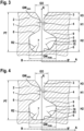
- Fig. 2 shows a circumferential groove 1 of a first embodiment of a pneumatic vehicle tire according to the invention.
- the cross section of the circumferential groove 1 is shown perpendicular to the circumferential direction of the pneumatic vehicle tire in the tread 2 of the pneumatic vehicle tire.
- the circumferential groove 1 is divided into three groove sections, a first groove section 4, a second inner groove section 5 and an outer third groove section 3. These groove sections are arranged in a radial direction R of the pneumatic vehicle tire.
- Both the first groove section 4 and the third groove section 3 are symmetrical to the radial direction R (shown by the directional arrow R in the Figure 2 ) is arranged.
- the third groove section 3 widens outwards towards the surface of the tread 2.
- the cross section of the outer third groove section 3 of the Figure 2 The circumferential groove 1 shown expands uniformly outwards in the radial direction R. Accordingly, the cross section of the third groove section 3 perpendicular to the circumferential direction has the shape of an isosceles and thus symmetrical trapezoid.
- Embodiment has a width GO in the axial direction A of 4 mm and a width GW min of 1.2 mm at its innermost point.
- This third groove section 3 is followed in the radial direction R by the first groove section 4. In the embodiment shown, this has a constant width in the axial direction A of 1.2 mm over its extension in the radial direction R.
- the first groove section 4 is thus narrower than the third groove section 3.
- the circumferential groove also has a second groove section 5. In this second groove section 5, the distance of the circumferential groove 1 to the center of the tire or the hub of the wheel that carries the pneumatic vehicle tire is the smallest.
- the second inner groove section 5 has in its bottom area, the bottom area of the circumferential groove 6, a deepest point 7 of the circumferential groove, which is the greatest distance from the surface of the tread 2 of the pneumatic vehicle tire. When the pneumatic vehicle tire is new, this distance is the tread depth PT of the pneumatic vehicle tire.
- the inner second groove section 5 adjoining the first groove section 4 has the largest cross-sectional area of the three groove sections of the circumferential groove. This cross-sectional area is asymmetrical to the radial direction. It extends on both sides of the radial direction and has an edge without corners.
- the circumferential groove 1 In the plane perpendicular to the circumferential direction of the pneumatic vehicle tire, the circumferential groove 1 has two sides.
- the side 8 of the circumferential groove points towards the center of the pneumatic vehicle tire.
- the side 9 of the circumferential groove points towards the outside of the pneumatic vehicle tire.
- Both sides of the circumferential groove 1 each have a curvature in the bottom area 6 of the circumferential groove 1, which is part of the second groove section 5.
- the radius of curvature of both sides is different.
- the radius of curvature R2 of the curvature of the side 8 of the circumferential groove, which points towards the center of the pneumatic vehicle tire, is smaller than the radius of curvature R1 of the side 9 of the circumferential groove, which points towards the outside of the vehicle tire.
- the radius of curvature R2 of the side 8 of the circumferential groove, which points towards the center of the pneumatic vehicle tire, is 2 mm in the exemplary embodiment.
- the radius of curvature R1 of the side 9 of the circumferential groove, which faces the outside of the pneumatic vehicle tire, is 4 mm.
- the radius of curvature R2 of the side 8, which faces the center of the vehicle is 50% smaller than the radius of curvature of the other side 9.
- the Cross-sectional area of the second groove section 5 is not asymmetrical over its entire height H2 in the radial direction R.
- the third groove section 3 has a height H3 of 2 mm in the direction of the radial direction R.
- the first groove section 4 has a height H1 of 3.5 mm in the direction of the radial direction R.
- the second groove section 5 has a height H2 of 6.5 mm in the direction of the radial direction R. Of this height, 73.8% of the height in the inner region of the second groove section 5 is asymmetrical.
- the asymmetrical region of the second groove section 5 therefore has a height of 4.8 mm in the radial direction R.
- the cross-sectional area of the second groove section 5 between the axial direction R and the side 8 of the circumferential groove 1, which faces the center of the pneumatic vehicle tire is in the embodiment shown approximately 1.1% smaller than the cross-sectional area of the second groove section 5 between the radial direction R and the side 9 of the circumferential groove 1, which faces the outside of the pneumatic vehicle tire.
- the percentage value is based on the area between the radial direction R and the side of the circumferential groove that faces the outside of the pneumatic vehicle tire.
- the area between the radial direction R and the side 8 of the circumferential groove 1 that faces the center of the pneumatic vehicle tire is even approximately 1.4% smaller than the cross-sectional area of the second groove section between the radial direction R and the side 9 of the circumferential groove 1 that faces the outside of the pneumatic vehicle tire.
- the ratio of the areas between the individual sides 8, 9 of the circumferential groove 1 and the radial direction R, together with the geometry of the cross-sectional area, is essential for the optimal behavior of the circumferential groove 1, both with regard to wet behavior and the transverse stiffness of the profile of the tread of the pneumatic vehicle tire. Area ratios between these areas that are typically used have already been described previously.
- Fig. 2 shown first embodiment of a circumferential groove 1 of a pneumatic vehicle tire according to the invention, that the edge of the cross-sectional area of the second groove section 5 has only one straight line on the side 8, which points towards the center of the vehicle tire, and no corners or other straight lines. Accordingly, the entire edge of the cross-sectional area of the second groove section 5 - apart from the straight line - only has curves. This leads to an increased rigidity of the groove profile, in particular on the side of the circumferential groove 1 facing the outside of the vehicle tyre, i.e. side 9.
- the straight line on the side 8, which points towards the center of the vehicle tire has an angle with respect to the radial direction R of 8.1°.
- the distance of the straight line from the radial direction R decreases with increasing distance from the surface of the tread 2.
- the angle with respect to the radial direction R is 0° to 15°, preferably 4° to 11° and particularly preferably 6° to 9°.
- the edge point with the maximum distance from the radial direction R which is located on the side 8 of the circumferential groove 1 which faces the center of the pneumatic vehicle tire, has a distance from the radial direction R of 3.9 mm in the axial direction A. This point of the maximum distance also has a distance in the radial direction R of 4 mm from the deepest point 7 of the second groove section 5.
- the point on the edge of the cross-sectional area of the second groove section 5, which is located on the side 9 of the circumferential groove 1 which faces the outside of the pneumatic vehicle tire has a distance of 4.6 mm from the radial direction R.
- this point has a distance in the radial direction R of 3.8 mm from the deepest point 7 of the circumferential groove 1.
- the two points of maximum distance on both sides 8, 9 of the circumferential groove also define a maximum width GWmax of the cross-sectional area of the third groove section 5.
- the maximum width GWmax of the second groove section 5 is 8.5 mm.
- the maximum width GWmax of the second groove section 5 is 4 mm to 10 mm, preferably 6 mm to 9 mm and particularly preferably 7 mm to 8 mm.
- the two points of maximum distance GWmax of the cross-sectional area of the second groove section 5 perpendicular to the circumferential direction were selected so that the circumferential groove 1 has both very good wet properties and a high transverse stiffness of the two sides 8, 9 of the circumferential groove, whereby groove fractures of the Circumferential groove can be avoided.
- the cross-sectional profile of the second groove section 5 of the circumferential grooves 1 of the inventive pneumatic vehicle tire is selected such that a circumferential groove 1 has very good wet properties, e.g. with regard to aquaplaning, and good resistance to groove breakage due to the cross-sectional area of the second groove section 5. It is precisely this compromise of properties that characterizes the invention.
- a ratio that describes this property very well is the ratio of the maximum width GWmax of the cross-sectional area of the second groove section 5 to the maximum height H2 of the cross-sectional area in the direction of the radial direction R.
- the maximum width GWmax perpendicular to the radial direction R of the cross-sectional area is 30.7% greater than the maximum height H2 of the cross-sectional area in the direction of the radial direction R.
- the distance to the radial direction R of the edge point of the cross-sectional area of the second groove section 5 perpendicular to the circumferential direction with the greatest distance to the radial direction R on the side 9 facing the outside of the pneumatic vehicle tire is greater than the distance of the edge point on the other side 8 to the radial direction R, which has the greatest distance to the radial direction R.
- the distance of the edge point on the side 9 facing the outside of the pneumatic vehicle tire is 17.9% greater in the exemplary embodiment than the corresponding distance of the edge point to the radial direction R, which has the maximum distance on the side 8 facing the center of the pneumatic vehicle tire.
- the distance of the edge point with maximum distance from the radial direction on the side 9 facing the outside of the pneumatic vehicle tire is 5% to 35% larger, preferably 8% to 25% larger and particularly preferably 12% to 18% larger than on the side 8 facing the center of the pneumatic vehicle tire.
- the distance of the edge point of the cross-sectional area of the second groove section 5 perpendicular to the circumferential direction with the greatest distance to the radial direction R on the side 9 facing the outside of the pneumatic vehicle tire to the deepest point 7 of the circumferential groove is 3.8 mm in the radial direction with a maximum height H2 of the Cross-sectional area of the second groove section of 6.5 mm. Accordingly, the distance of this edge point to the deepest point of the circumferential groove in the radial direction R is 58.4% of the maximum height H2 of the cross-sectional area of the second groove section 5.
- the distance of the edge point of the cross-sectional area of the second groove section 5 perpendicular to the circumferential direction with the greatest distance to the radial direction R on the side 9 facing the outside of the pneumatic vehicle tire to the deepest point 7 of the circumferential groove in the radial direction R is between 30% and 80% of the maximum height H2 of the cross-sectional area of the second groove section 5, preferably between 50% and 75% of the maximum height H2 of the cross-sectional area of the second groove section 5 and particularly preferably between 55% and 65% of the maximum height H2 of the cross-sectional area of the second groove section 5.
- the distance of the edge point of the cross-sectional area of the second groove section 5 perpendicular to the circumferential direction with the greatest distance to the radial direction R on the side 8 that is free to the center of the pneumatic vehicle tire to the lowest point 7 of the circumferential groove 1 is 4 mm in the radial direction R in the exemplary embodiment. Accordingly, the distance of this edge point to the lowest point 7 of the circumferential groove 1 is 61.5% of the maximum height H2 of the cross-sectional area of the second groove section 5 in the direction of the radial direction R.
- the distance of the edge point of the cross-sectional area of the second groove section 5 perpendicular to the circumferential direction with the greatest distance to the radial direction R on the side 8 that points towards the center of the pneumatic vehicle tire to the deepest point 7 of the circumferential groove in the radial direction R is between 50% and 80% of the maximum height H2 of the cross-sectional area of the second groove section 5, preferably between 55% and 75% of the maximum height H2 of the cross-sectional area of the second groove section 5 and particularly preferably between 60% and 70% of the maximum height H2 of the cross-sectional area of the second groove section 5.
- the bottom area 6 of the circumferential groove 1 typically has, as shown in the embodiment, the two radii of curvature R1 and R2. In the bottom area 6 of the circumferential groove 1, these are the smallest radii of curvature of both sides 8 and 9 of the circumferential groove 1.
- the smallest radius of curvature R1 of the side 9 of the circumferential groove 2 in the bottom area 6, which faces the outside of the pneumatic vehicle tire, is larger than the smallest radius of curvature R2 of the side 8 in the bottom area 6, which faces the center of the pneumatic vehicle tire.
- the radius of curvature R1 is 4 mm and the radius of curvature R2 is 2 mm. Accordingly, the radius of curvature R2 located at the bottom of the side 8 of the circumferential groove 2 facing the center of the pneumatic vehicle tire is 50% smaller than the radius of curvature R1 of the other side 9.
- the smallest radius of curvature R1 of the side 9 in the bottom region 6 of the circumferential groove 1 in a pneumatic vehicle tire according to the invention has a value between 1.5 mm and 5.0 mm, preferably between 2.0 mm and 4.2 mm and particularly preferably between 3.5 and 4.0 mm.
- the smallest radius of curvature R2 of the side 8 in the bottom region 6 of the circumferential groove 1 in a pneumatic vehicle tire according to the invention typically has a value between 0.7 mm and 2.5 mm, preferably between 1.0 mm and 2.2 mm and particularly preferably between 1.5 and 2.0 mm.
- the Fig. 2 the cross section of the outer third groove section 3 of the circumferential groove 1 shown expands evenly outwards in the axial direction A. Therefore, both sides of the third groove section 3 form straight lines which have an angle to the radial direction R, which in the exemplary embodiment is 35°.
- the width GO of the first groove section 3 tapers from the surface of the tread 2 of the pneumatic vehicle tire in the new state of 4 mm to a width in the axial direction of 1.2 mm (GWmin).
- the material of the tread 2 of the pneumatic vehicle tire in which the circumferential groove shown is arranged is usually a rubber mixture.
- the material has a modulus of elasticity in the range of 11 MaPa at 60°C, preferably a modulus of elasticity in the range of 4.0 to 9.0 MaPa and particularly preferably a modulus of elasticity in the range of 5.5 to 8.0 MaPa. In the exemplary embodiment shown, a modulus of elasticity of 6.5 MaPa is used. The modulus of elasticity is determined in accordance with DIN EN 527.
- the tread of a pneumatic vehicle tire according to the invention has a loss factor tan ⁇ which is usually in the range of 0.03 to 0.25 at 60°C, preferably in the range of 0.05 to 0.2 at 60°C and particularly preferably in the range of 0.75 to 0.1 at 60°C. In the exemplary embodiment shown, the loss factor tan ⁇ is 0.085.
- the loss factor of the material of tread 2 is determined according to DIN 52 513 and describes the hysteresis behavior of the viscoelastic material of tread 2.
- Fig. 3 shows a circumferential groove 1 of a second embodiment of a pneumatic vehicle tire according to the invention.
- the same and corresponding components are identified by the same reference numerals as in the Figure 2 shown first embodiment.
- FIG. 2 Shown is as in Fig. 2 the cross section of the circumferential groove 1 perpendicular to the circumferential direction of the pneumatic vehicle tire in the tread 2 of the pneumatic vehicle tire.
- the circumferential groove 1 is divided into three groove sections, a first groove section 4, and a second inner groove section 5 and an outer third groove section 3. These groove sections are arranged in a radial direction R of the pneumatic vehicle tire.
- the first groove portion 4 and the third groove portion 3 are unchanged from the first embodiment. Therefore, both the first groove portion 4 and the third groove portion 3 are symmetrical to the radial direction R (shown by the direction arrow R in the Figure 3 ). Further details on these groove sections can be found in Fig. 2 shown first embodiment.
- the circumferential groove 1 shown has a second groove section 5 which is designed differently than the one shown in Fig. 2 shown first embodiment. Also in this second groove section 5, the distance of the circumferential groove 1 to the center of the tire or the hub of the wheel that carries the pneumatic vehicle tire 1 is the smallest. Accordingly, the second inner groove section 5 has a lowest point 7 of the circumferential groove in its bottom area, the bottom area 6 of the circumferential groove 1, which is the greatest distance from the surface of the tread of the pneumatic vehicle tire. When the pneumatic vehicle tire is new, this distance is the tread depth PT of the pneumatic vehicle tire.
- the second inner groove section 5 adjoining the first groove section has the largest cross-sectional area of the three groove sections of the circumferential groove. This cross-sectional area is asymmetrical to the radial direction. It extends on both sides of the radial direction and has an edge without corners.
- the circumferential groove 1 In the plane perpendicular to the circumferential direction of the pneumatic vehicle tire, the circumferential groove 1 has two sides.
- the side 8 of the circumferential groove faces the center of the pneumatic vehicle tire.
- the side 9 of the circumferential groove faces the outside of the pneumatic vehicle tire.
- Both sides of the circumferential groove face the same direction as in Fig. 2 shown first embodiment in the bottom area 6 of the circumferential groove 1, which is part of the second groove section 5, each has a curvature. The radius of curvature of both sides is different.
- the radius of curvature of the curvature R2 of the side 8 of the circumferential groove that faces the center of the pneumatic vehicle tire is smaller than the radius of curvature R1 of the side 9 of the circumferential groove that faces the outside of the vehicle tire.
- the radius of curvature R2 of the side 8 of the circumferential groove that faces the center of the pneumatic vehicle tire is 2 mm in the embodiment.
- the radius of curvature R1 of the side 9 of the circumferential groove that faces the outside of the pneumatic vehicle tire is 4 mm.
- the radius of curvature R2 of the side 8 facing the vehicle center is 50% smaller than the radius of curvature R1 of the other side 9.
- the cross-sectional area of the second groove section 5 is not asymmetrical over its entire height in the radial direction R.
- the second groove section 5 has a height H2 of 6.5 mm in the radial direction. Of this height, 78.7% of the height is in the inner area of the third groove section 5 is asymmetrical. The asymmetrical region of the third groove section 5 therefore has a height of 5.12 mm in the radial direction R.
- the edge of the cross-sectional area of the third groove section 5 in the Fig. 3 has a straight line on both sides 8 and 9 and no corners or other straight lines. Accordingly, the entire edge of the cross-sectional area of the third groove section 5 - apart from the two straight lines - has curvatures.
- the straight line 15 on side 9 of the circumferential groove 1, which faces the outside of the vehicle tire, is designed in such a way that it contributes to an increased rigidity of the groove profile, in particular on side 9.
- the straight line 15 is inclined by 33.3° with respect to the radial direction R and runs towards the radial direction R with increasing depth of the circumferential groove. It extends in the radial direction R over 1.95 mm, which corresponds to 30.0% of the maximum height H2 of the cross-sectional area of the second groove section 5.
- the edge point with the maximum distance from the radial direction R which is located on the side 8 of the circumferential groove 1 which faces the center of the pneumatic vehicle tire, has a distance from the radial direction R of 4 mm in the axial direction A.
- the two points of the maximum distance on both sides 8, 9 of the circumferential groove also define a maximum width GWmax of the cross-sectional area of the second groove section 5 in the axial direction A.
- the maximum width GWmax of the second groove section 5 is 8.27 mm.
- the straight line 15 of side 9 of the circumferential groove 1, which points towards the outside of the pneumatic vehicle tire, begins on side 9, viewed from the surface of the tread 2 of the pneumatic vehicle tire, almost below the point on side 9 which has the largest section to the axial direction R. Opposite this point, the straight line is oriented inwards towards the center of the tire and reduces the width of the second groove section 5 by its inclination to the radial direction R.
- the distance of the straight line in the radial direction R at its innermost point is 1.50 mm, which corresponds to 23.1% of the maximum height H2 of the cross-sectional area of the second groove section 5 in the radial direction R, and at its outermost point is 3.45 mm, which corresponds to 53.1% of the maximum height H2 of the cross-sectional area of the second groove section 5 in the radial direction R.
- the straight line 15 is followed inwards by a curved transition region and the area of the bottom area 6 with the radius of curvature R1.
- the two points of the maximum distance GWmax of the cross-sectional area of the second groove section 5 perpendicular to the circumferential direction and the straight line 15 on the side 9 of the circumferential groove 1 were generally chosen so that the circumferential groove 1 has both very good wet properties and a high transverse stiffness of the two sides 8,9 of the circumferential groove, thereby preventing groove breakages in the circumferential groove.
- the cross-sectional profile of the third groove section 5 of the circumferential grooves 1 of the inventive pneumatic vehicle tire is generally chosen so that a circumferential groove 1 has very good wet properties, e.g. with regard to aquaplaning, and good resistance to groove breakages due to the cross-sectional area of the second groove section 5. It is precisely this compromise of properties that characterizes the invention.
- a ratio that describes this property very well is the ratio of the maximum width GWmax of the cross-sectional area of the second groove section 5 to the maximum height H2 of the cross-sectional area in the direction of the radial direction R.
- the maximum width GWmax perpendicular to the radial direction R of the cross-sectional area is 27.2% larger than the maximum height H2 of the cross-sectional area in the direction of the radial direction R.
- the distance to the radial direction R of the edge point of the Cross-sectional area of the second groove section 5 perpendicular to the circumferential direction with the greatest distance to the radial direction R on the side 9 facing the outside of the pneumatic vehicle tire is greater than the distance of the edge point on the other side 8 to the radial direction R, which has the greatest distance to the radial direction R.
- the distance of the edge point on the side 9 facing the outside of the pneumatic vehicle tire is 17.9% greater in the exemplary embodiment than the corresponding distance of the edge point to the radial direction R, which has the maximum distance on the side 8 facing the center of the pneumatic vehicle tire.
- the distance of the edge point of the cross-sectional area of the second groove section 5 perpendicular to the circumferential direction with the greatest distance to the radial direction R on the side 9 facing the outside of the pneumatic vehicle tire to the deepest point 7 of the circumferential groove is 3.8 mm in the radial direction R with a maximum height H2 of the cross-sectional area of the second groove section of 6.5 mm in the radial direction R. Accordingly, the distance of this edge point to the deepest point of the circumferential groove in the radial direction R is 57% of the maximum height H2 of the cross-sectional area of the second groove section 5.
- the distance of the edge point of the cross-sectional area of the second groove section 5 perpendicular to the circumferential direction with the greatest distance to the radial direction R on the side 8 that is free to the center of the pneumatic vehicle tire to the deepest point 7 of the circumferential groove 1 is 4 mm in the radial direction R in the exemplary embodiment. Accordingly, the distance of this edge point to the deepest point of the circumferential groove 6 is 61.5% of the maximum height H2 of the cross-sectional area of the second groove section 5 in the direction of the radial direction R.
- This positioning of the outermost edge point of the side 8 of the circumferential groove that faces the center of the pneumatic vehicle tire increases the water absorption capacity of the second groove section 5, thereby improving the contribution of the circumferential groove 1 to the good wet behavior of the pneumatic vehicle tire according to the invention.
- the base region 6 of the circumferential groove 1 has the two radii of curvature R1 and R2 already mentioned. These are the main radii of curvature of the two sides 8 and 9 in the base region of the circumferential groove 1, ie the radii of curvature by which the contour of both sides in the base region is predetermined over the largest side length.
- the main radius of curvature R1 of the side 9 of the circumferential groove 1, which faces the outside of the pneumatic vehicle tire, in embodiments of the pneumatic vehicle tire according to the invention such as the one in Figure 3 shown is larger than the main radius of curvature R2 of the side 8 facing the center of the pneumatic vehicle tire.
- the main radius of curvature R1 is 4 mm and the main radius of curvature R2 is 2 mm. Accordingly, the main radius of curvature R2 located at the bottom portion of the side 8 of the circumferential groove 1 facing the center of the pneumatic vehicle tire is 50% smaller than the main radius of curvature R1 of the other side.
- the main radius of curvature R2 which is located in the bottom region of the side 8 of the circumferential groove 1 which faces the center of the pneumatic vehicle tire, is 20% smaller than the main radius of curvature R1 in the bottom region of the other side, preferably 35% smaller than the main radius of curvature R1 in the bottom region of the other side, and particularly preferably 50% smaller than the main radius of curvature R1 in the bottom region of the other side.
- the material of the tread 2 of the pneumatic vehicle tire according to the invention with the Fig. 3 The second embodiment of a circumferential groove 1 shown corresponds to that of the Fig. 2 shown first embodiment of a circumferential groove 1.
- Fig. 4 shows a circumferential groove 1 of a third embodiment of a pneumatic vehicle tire according to the invention.
- the same and corresponding components are identified by the same reference numerals as in the Figure 2 shown first embodiment.
- FIG. 2 Shown is as in Fig. 2 the cross section of the circumferential groove 1 perpendicular to the circumferential direction of the pneumatic vehicle tire in the tread 2 of the pneumatic vehicle tire.
- the circumferential groove 1 is divided into three groove sections, a first groove section 4, a second inner groove section 5 and an outer third Groove section 3,. These groove sections are arranged in a radial direction R of the vehicle pneumatic tire.
- first groove portion 4 and the third groove portion 3 are unchanged from the first and second embodiments. Therefore, both the first groove portion 4 and the third groove portion 3 are symmetrical to the radial direction R (shown by the direction arrow R in the Figure 4 ). Further details on these groove sections can be found in Fig. 2 shown first embodiment.
- the circumferential groove 1 shown has a second groove section 5 which is designed differently than the one shown in Fig. 2 shown first embodiment.
- the distance of the circumferential groove 2 to the center of the tire or the hub of the wheel that carries the pneumatic vehicle tire 1 is the smallest.
- the second inner groove section 5 has in its bottom area, the bottom area 6 of the circumferential groove 1, a lowest point 7 of the circumferential groove that is the greatest distance from the surface of the tread of the pneumatic vehicle tire. When the pneumatic vehicle tire is new, this distance is the tread depth PT of the pneumatic vehicle tire.
- the second inner groove section 5 adjoining the first groove section has the largest cross-sectional area of the three groove sections of the circumferential groove. This cross-sectional area is asymmetrical to the radial direction. It extends on both sides of the radial direction and has an edge without corners.
- the circumferential groove 1 In the plane perpendicular to the circumferential direction of the pneumatic vehicle tire, the circumferential groove 1 has two sides.
- the side 8 of the circumferential groove faces the center of the pneumatic vehicle tire.
- the side 9 of the circumferential groove faces the outside of the pneumatic vehicle tire.
- Both sides of the circumferential groove face the same direction as in Fig. 2 shown first embodiment in the bottom area 6 of the circumferential groove 1, which is part of the second groove section 5, each has a curvature. The radius of curvature of both sides is different.
- the radius of curvature of the curvature R2 of the side 8 of the circumferential groove, which faces the center of the pneumatic vehicle tire, is smaller than the radius of curvature R1 of the side 9 of the circumferential groove, which faces the outside of the vehicle tire.
- the radius of curvature R2 of the side 8 of the circumferential groove, which faces the vehicle center of the pneumatic vehicle tire, is 2 mm in the exemplary embodiment.
- the radius of curvature R1 of the side 9 of the circumferential groove, which faces the outside of the pneumatic vehicle tire, is 4 mm.
- the radius of curvature R2 of the side 8, which faces the vehicle center is 50% smaller than the radius of curvature R1 of the other side 9.
- the second groove section 5 has a height H2 of 6.5 mm in the radial direction R. Of this height, 78.7% of the height in the inner region of the second groove section 5 is asymmetrical. The asymmetrical region of the third groove section 5 therefore has a height of 5.12 mm in the radial direction R.
- the edge of the cross-sectional area of the second groove section 5 in the Fig. 4 has a straight line on both sides 8 and 9 and no corners or other straight lines. Accordingly, the entire edge of the cross-sectional area of the second groove section 5 - apart from the two straight lines - has curvatures.
- the straight line 16 on side 9 of the circumferential groove 1, which faces the outside of the pneumatic vehicle tire, is designed such that it contributes to an increased rigidity of the groove profile, in particular on side 9.
- the straight line 16 is inclined by 13.9° with respect to the radial direction R and runs towards the radial direction R as the depth of the circumferential groove increases. It extends in the radial direction R over 0.93 mm, which corresponds to 14.3% of the maximum height H2 of the cross-sectional area of the second groove section 5.
- the straight line 16 on the side 9 of the circumferential groove, which faces the outside of the pneumatic vehicle tire, in this third embodiment is shorter than the corresponding straight line 15 of the second embodiment and has a smaller inclination with respect to the radial direction.
- a straight line that belongs to the edge of the cross-sectional area of the second groove section 5 perpendicular to the circumferential direction extends on the side 9 of the circumferential groove that faces the outside of the pneumatic vehicle tire over at most 45% of the maximum height H2 of the cross-sectional area of the second groove section 5, preferably over at most 20% of the maximum height H2 of the cross-sectional area of the second groove section 5 and particularly preferably over at most 5% of the maximum height H2 of the cross-sectional area of the second groove section 5.
- Such a straight line typically has an inclination with respect to the radial direction R of at least 5°, preferably at least 20° and particularly preferably at least 25°.
- a longer straight line on the side 9 of the circumferential groove 1 has a greater inclination with respect to the radial direction R.
- the edge point with the maximum distance from the radial direction R which is located on the side 8 of the circumferential groove 1 which faces the center of the pneumatic vehicle tire, has a distance from the radial direction R of 4 mm in the axial direction A.
- the two points of the maximum distance on both sides 8, 9 of the circumferential groove also define a maximum width GWmax of the cross-sectional area of the second groove section 5 in the axial direction A.
- the maximum width GWmax of the second groove section 5 is 8.27 mm.
- the straight line 16 of side 9 of the circumferential groove 1, which points towards the outside of the pneumatic vehicle tire, begins on side 9, as viewed from the surface of the tread 2 of the pneumatic vehicle tire, almost below the point on side 9 which has the largest section to the axial direction R. Opposite this point, the straight line is directed inwards towards the tire center and reduces the width of the second Groove section 5 by its inclination to the radial direction R.
- the distance of the straight line in the radial direction R at its innermost point is 2.82 mm, which corresponds to 43.4% of the maximum height H2 of the cross-sectional area of the second groove section 5, and at its outermost point 3.75 mm, which corresponds to 57.7% of the maximum height H2 of the cross-sectional area of the second groove section 5.
- the straight line 16 is followed inwards by the area of the base area 6 with the radius of curvature R1 after a curved transition area.
- the two points of the maximum distance GWmax of the cross-sectional area of the third groove section 5 perpendicular to the circumferential direction and the straight line 16 on the side 9 of the circumferential groove 1 were chosen so that the circumferential groove 1 has both very good wet properties and a high transverse stiffness of the two sides 8,9 of the circumferential groove, thereby preventing groove breakages in the circumferential groove.
- the cross-sectional profile of the second groove section 5 of the circumferential grooves 1 of the inventive pneumatic vehicle tire is chosen so that a circumferential groove 1 has very good wet properties, e.g. with regard to aquaplaning, and good resistance to groove breakages due to the cross-sectional area of the third groove section 5. It is precisely this compromise of properties that characterizes the invention.
- a ratio that describes this property very well is the ratio of the maximum width GWmax of the cross-sectional area of the second groove section 5 to the maximum height H2 of the cross-sectional area in the direction of the radial direction R.
- the maximum width GWmax perpendicular to the radial direction R of the cross-sectional area is 27.2% greater than the maximum height H2 of the cross-sectional area in the direction of the radial direction R.
- the distance to the radial direction R of the edge point of the cross-sectional area of the second groove section 5 perpendicular to the circumferential direction with the greatest distance to the radial direction R on the side 9 facing the outside of the pneumatic vehicle tire is greater than the distance of the edge point on the other side 8 to the radial direction R, which has the greatest distance to the radial direction R.
- the distance of the edge point on the side 9 facing the outside of the pneumatic vehicle tire is 17.9% greater in the exemplary embodiment than the corresponding Distance of the edge point to the radial direction R which has the maximum distance on the side 8 facing the centre of the vehicle tyre.
- the distance of the edge point of the cross-sectional area of the second groove section 5 perpendicular to the circumferential direction with the greatest distance to the radial direction R on the side 9 facing the outside of the pneumatic vehicle tire to the deepest point 7 of the circumferential groove is 3.8 mm with a maximum height H2 of the cross-sectional area of the third groove section of 6.5 mm. Accordingly, the distance of this edge point to the deepest point of the circumferential groove in the radial direction R is 58.4% of the maximum height of the cross-sectional area of the third groove section 5.
- the distance of the edge point of the cross-sectional area of the second groove section 5 perpendicular to the circumferential direction with the greatest distance to the radial direction R on the side 8 that is free to the center of the pneumatic vehicle tire to the deepest point 7 of the circumferential groove 1 is 4 mm in the exemplary embodiment. Accordingly, the distance of this edge point to the deepest point of the circumferential groove 6 is 61.5% of the maximum height H2 of the cross-sectional area of the second groove section 5 in the direction of the radial direction R.
- This positioning of the outermost edge point of the side 8 of the circumferential groove that faces the center of the pneumatic vehicle tire increases the water absorption capacity of the second groove section 5, thereby improving the contribution of the circumferential groove 1 to the good wet behavior of the pneumatic vehicle tire according to the invention.
- the bottom area 6 of the circumferential groove 1 typically has, as shown in the embodiment, the two radii of curvature R1 and R2. In the bottom area 6 of the circumferential groove 1, these are the smallest radii of curvature of both sides 8 and 9 of the circumferential groove 1.
- the smallest radius of curvature R1 of the side 9 of the circumferential groove 1 in the bottom area 6, which faces the outside of the pneumatic vehicle tire is larger than the smallest radius of curvature R2 of the side 8 in the bottom area 6, which faces the center of the pneumatic vehicle tire.
- the radius of curvature R1 is 4 mm and the radius of curvature R2 is 2 mm. Accordingly, the radius of curvature R2, which is located at the bottom portion 6 of the side 8 of the circumferential groove 1 facing the center of the pneumatic vehicle tire, is 50% smaller than the radius of curvature R1 of the other side 9.
- the material of the tread 2 of the pneumatic vehicle tire according to the invention with the Fig. 4 The third embodiment of a circumferential groove 1 shown corresponds to that of the Fig. 2 shown first embodiment of a circumferential groove 1.
- Fig. 5 shows a circumferential groove 1 of a fourth particularly preferred embodiment of a pneumatic vehicle tire according to the invention.
- the same and corresponding components are identified by the same reference numerals as in the Figure 2 shown first embodiment.
- FIG. 2 Shown is as in Fig. 2 the cross section of the circumferential groove 1 perpendicular to the circumferential direction of the pneumatic vehicle tire in the tread 2 of the pneumatic vehicle tire.
- the circumferential groove 1 is divided into three groove sections, a first groove section 4, and a second inner groove section 5 and an outer third groove section 3. These groove sections are arranged in a radial direction R of the pneumatic vehicle tire.
- the first groove portion 4 and the third groove portion 3 are unchanged from the first embodiment. Therefore, both the first groove portion 4 and the third groove portion 3 are symmetrical to the radial direction R (shown by the direction arrow R in the Figure 5 ). Further details on these groove sections can be found in Fig. 2 shown first embodiment.
- the Figure 5 shown circumferential groove 1 of the fourth embodiment has a second groove section 5.
- the distance of the circumferential groove 1 to the center of the tire or the hub of the wheel that carries the pneumatic vehicle tire is the smallest.
- the second inner groove section 5 has in its bottom area, the bottom area 6 of the circumferential groove 1, a deepest point 7 of the circumferential groove, which is the greatest distance from the surface of the tread 2 of the vehicle pneumatic tire. When the vehicle pneumatic tire is new, this distance is the tread depth PT of the vehicle pneumatic tire.
- the inner second groove section 5 adjoining the first groove section also has the largest cross-sectional area of the three groove sections of the circumferential groove in the fourth embodiment. This cross-sectional area is asymmetrical to the radial direction. It extends on both sides of the radial direction and has an edge without corners.
- Both sides of the Fig. 5 shown circumferential groove 1, the side 8 which faces the center of the pneumatic vehicle tire and the side 9 which faces the outside of the pneumatic vehicle tire each have a curvature in the bottom region 6 of the circumferential groove 1, which is part of the second groove section 5.
- the radius of curvature of both sides is different.
- the radius of curvature R2 of the curvature of the side 8 of the circumferential groove which faces the center of the pneumatic vehicle tire is smaller than the radius of curvature R1 of the side 9 of the circumferential groove which faces the outside of the vehicle tire.
- the radius of curvature R2 of the side 8 of the circumferential groove which faces the center of the pneumatic vehicle tire is 2 mm in the exemplary embodiment.
- the radius of curvature R1 of the side 9 of the circumferential groove which faces the outside of the pneumatic vehicle tire is 4 mm.
- the radius of curvature R2 of the side 8 facing the vehicle center is 50% smaller than the radius of curvature of the other side 9.
- the cross-sectional area of the second groove section 5 is not asymmetrical over its entire height H2 in the radial direction R.
- the second groove section 5 has a height H2 of 6.5 mm in the radial direction in the direction R. Of this height, 76% of the height in the inner region of the second groove section 5 is asymmetrical.
- the asymmetrical area of the second groove section 5 therefore has a height of 4.94 mm in the radial direction R.
- the cross-sectional area of the second groove section 5 between the axial direction R and the side 8 of the circumferential groove 1, which faces the center of the pneumatic vehicle tire is in the embodiment shown approximately 22.2% larger than the cross-sectional area of the second groove section 5 between the radial direction R and the side 9 of the circumferential groove 1, which faces the outside of the pneumatic vehicle tire.
- the percentage value is based on the area between the radial direction R and the side of the circumferential groove, which faces the outside of the pneumatic vehicle tire.
- the area between the radial direction R and the side 8 of the circumferential groove 1, which faces the center of the pneumatic vehicle tire is even approximately 29.7% larger than the cross-sectional area of the second groove section between the radial direction R and the side 9 of the circumferential groove 1, which faces the outside of the pneumatic vehicle tire.
- the ratio of the areas between the individual sides 8 and 9 of the circumferential groove 1 and the radial direction R, together with the geometry of the cross-sectional area, is essential for the optimal behavior of the circumferential groove 1, both with regard to wet behavior and the transverse stiffness of the profile of the tread of the pneumatic vehicle tire.
- the edge of the cross-sectional area of the second groove section 5 has only one straight line on the side 8 that faces the center of the vehicle tire, and no corners or other straight lines. Accordingly, the entire edge of the cross-sectional area of the second groove section 5 - apart from the straight line - only has curves. This leads to increased rigidity of the groove profile, in particular on the side of the circumferential groove 1 that faces the outside of the vehicle tire, ie the side 9.
- the straight line on the side 8, which points towards the centre of the vehicle tyre has an angle of 8.4° with respect to the radial direction R.
- the distance of the straight line from the radial direction R decreases with increasing distance from the surface of the tread 2.
- the edge point with the maximum distance from the radial direction R which is located on the side 8 of the circumferential groove 1 which faces the center of the pneumatic vehicle tire, has a distance from the radial direction R of 3.45 mm in the axial direction A. This point of the maximum distance also has a distance in the radial direction R of 4.2 mm from the deepest point 7 of the second groove section 5.
- the point of the edge of the cross-sectional area of the second groove section 5 which is on the side 9 of the circumferential groove 1 which faces the outside of the pneumatic vehicle tire, is at a distance of 3.95 mm from the radial direction R. In addition, this point is at a distance of 4.0 mm in the radial direction R from the deepest point 7 of the circumferential groove 1.
- the two points of maximum distance on both sides 8, 9 of the circumferential groove also define a maximum width GWmax of the cross-sectional area of the third groove section 5. In the exemplary embodiment shown, the maximum width GWmax of the second groove section 5 is 7.4 mm.
- the two points of maximum distance GWmax of the cross-sectional area of the second groove section 5 perpendicular to the circumferential direction were selected such that the circumferential groove 1 has both very good wet properties and great transverse rigidity of the two sides 8 and 9 of the circumferential groove, thereby preventing groove breakages in the circumferential groove.
- the cross-sectional profile of the second groove section 5 of the circumferential grooves 1 of the inventive pneumatic vehicle tire is selected such that a circumferential groove 1 has very good wet properties, e.g. with regard to aquaplaning, and good resistance to groove breakage due to the cross-sectional area of the second groove section 5.
- a very good compromise of these properties is characterized by the Figure 5 shown circumferential groove 1.
- a ratio that describes this property very well is the ratio of the maximum width GWmax of the cross-sectional area of the second groove section 5 to the maximum height H2 of the cross-sectional area in the direction of the radial direction R.
- the maximum width GWmax perpendicular to the radial direction R of the cross-sectional area is 13.8% greater than the maximum height H2 of the cross-sectional area in the direction of the radial direction R.
- the distance to the radial direction R of the edge point of the cross-sectional area of the second groove section 5 perpendicular to the circumferential direction with the greatest distance to the radial direction R on the side 9 facing the outside of the pneumatic vehicle tire is greater than the distance of the edge point on the other side 8 to the radial direction R, which has the greatest distance to the radial direction R.
- the distance of the edge point on the side 9 facing the outside of the pneumatic vehicle tire is 16.7% greater in the exemplary embodiment than the corresponding distance of the edge point to the radial direction R, which has the maximum distance on the side 8 facing the center of the pneumatic vehicle tire.
- the distance of the edge point of the cross-sectional area of the second groove section 5 perpendicular to the circumferential direction with the greatest distance to the radial direction R on the side 9 facing the outside of the pneumatic vehicle tire to the deepest point 7 of the circumferential groove is 4.0 mm in the radial direction with a maximum height H2 of the cross-sectional area of the second groove section of 6.5 mm. Accordingly, the distance of this edge point to the deepest point of the circumferential groove in the radial direction R is 61.5% of the maximum height H2 of the cross-sectional area of the second groove section 5.
- the distance of the edge point of the cross-sectional area of the second groove section 5 perpendicular to the circumferential direction with the greatest distance to the radial direction R on the side 8 that is free to the center of the pneumatic vehicle tire to the deepest point 7 of the circumferential groove 1 is 4.2 mm in the radial direction R in the exemplary embodiment. Accordingly, the distance of this edge point to the deepest point 7 of the circumferential groove 1 is 64.6% of the maximum height H2 of the cross-sectional area of the second groove section 5 in the direction of the radial direction R.
- This positioning of the outermost edge point of the side 8 of the circumferential groove that faces the center of the pneumatic vehicle tire increases the water absorption capacity of the second groove section 5, thereby improving the contribution of the circumferential groove 1 to the good wet behavior of the pneumatic vehicle tire according to the invention.
- the bottom area 6 of the circumferential groove 1 has in the Figure 5 shown embodiment, the two radii of curvature R1 and R2. These are in the bottom area 6 of the circumferential groove 1 the smallest radii of curvature of both sides 8 and 9 of the circumferential groove 1.
- the smallest radius of curvature R1 of the side 9 of the circumferential groove 2 in the bottom area 6, which faces the outside of the pneumatic vehicle tire is larger than the smallest radius of curvature R2 of the side 8 in the bottom area 6, which faces the center of the pneumatic vehicle tire.
- the radius of curvature R1 is 4 mm and the radius of curvature R2 is 2 mm. Accordingly, the Radius of curvature R2 located at the bottom portion of side 8 of circumferential groove 2 facing the center of the pneumatic vehicle tire is 50% smaller than the radius of curvature R1 of the other side 9.
- Fig. 6 shows a circumferential groove 1 of a fifth embodiment of a pneumatic vehicle tire according to the invention.
- the same and corresponding components are identified by the same reference numerals as in the Figure 5 shown fourth embodiment.
- Shown is as in Fig. 5 the cross section of the circumferential groove 1 perpendicular to the circumferential direction of the pneumatic vehicle tire in the tread 2 of the pneumatic vehicle tire.
- the circumferential groove 1 is only divided into two groove sections, a first outer groove section 4 and a second inner groove section 5. These groove sections are arranged in a radial direction R of the pneumatic vehicle tire.
- the first groove section 4 is arranged symmetrically to the radial direction.
- the first outer groove section 4 ends at the surface of the tread 2 of the pneumatic vehicle tire. In the exemplary embodiment shown, it has a constant width GW min in the axial direction A, which is 1.2 mm, over its extension in the radial direction R.
- the first radial groove section has a height H1 of 5.5 mm in the direction of the radial direction R.
- the height H1 of the first radial groove section in the direction of the radial direction R is typically 2 mm to 11 mm, preferably 4 mm to 9 mm and particularly preferably 5 mm to 7 mm.
- the second inner groove section 5 adjoining the first groove section 4 in the fifth embodiment shown has a cross section in the axial direction A which is wider than this width GW min .
- the second inner groove section 5 is the one shown in Figure 6 showed fifth embodiment compared to that in Figure 5 shown fourth embodiment remains unchanged.
- the tread 2 of a pneumatic vehicle tire according to the invention is shown.
- the tread has four circumferential grooves, the outer grooves 10 and 11 and the inner grooves 12 and 13.
- the two outer grooves 10 and 11 have a cross section perpendicular to the circumferential direction, as shown in the Figures 2 to 5 is shown. Accordingly, the two outer grooves 10 and 11 have three groove sections 3, 4 and 5.
- the pneumatic vehicle tire Due to the inventive design of the outer grooves 10, 11 of the pneumatic vehicle tire shown, the pneumatic vehicle tire has very good wet properties, particularly with regard to aquaplaning, and nevertheless a high transverse stiffness, which prevents the formation of groove breaks.
- This improvement in the profile of the outer grooves 10, 11 takes into account in particular a permanently even rolling and thus a permanently uniform stress on the pneumatic vehicle tire and also the lateral forces that act on the pneumatic vehicle tire during vehicle operation, whereby the shoulder area of the pneumatic vehicle tire is particularly stressed.
- the tread 2 is shown in a further embodiment of a pneumatic vehicle tire according to the invention.
- the tread 2 has four circumferential grooves. These are two outer grooves 10, 11 and two inner grooves 12, 13.
- the inner grooves 12, 13 have a U-shaped profile, which can alternatively also be V-shaped.
- Both outer grooves 10, 11 have two different cross sections perpendicular to the circumferential direction in partial sections of the circumference.
- the partial sections alternate with the two different cross sections of the circumferential groove perpendicular to the circumferential direction over the circumference. At the end of a partial section, one cross section of the circumferential groove merges into the other cross section of the circumferential groove.
- the cross section of the circumferential groove is composed of three adjoining groove sections 3, 4 and 5, which are arranged one behind the other in the radial direction R of the pneumatic vehicle tire.
- Such cross sections of the circumferential groove of a pneumatic vehicle tire according to the invention have been described previously and are shown by way of example in the Figures 2 to 5 shown.
- Fig. 8 In such a section the line B, B ⁇ is shown. It runs through the circumferential groove 11 in the axial direction of the tread 2.
- the line B, B ⁇ is also shown in the Figures 2 to 5 , along which the cross section of the circumferential groove 1 is shown in the figures.
- the cross section in this circumferential section is characterized by the properties that are reproduced in claim 1.
- this cross section of the circumferential groove has already been described previously and can also be found in Fig. 8 in the tread 2 of the pneumatic vehicle tire.
- a cross-section of the circumferential groove 11 perpendicular to the circumferential direction which has a V-shaped and preferably a U-shaped profile.
- the U-shaped profile is asymmetrical, with the side 8 of the circumferential groove facing the center of the vehicle having a smaller radius of curvature in the bottom region 6 of the circumferential groove.
- the cross-section used in this section of the circumferential groove is e.g.
- the sections with varying cross-sections have the same length in the circumferential direction.
- length ratios of the sections with the different cross-sections that deviate from this are also possible.
- the proportion of the length of the sections of the circumference of the pneumatic vehicle tire that have a cross-section that is composed of at least two groove sections 4 and 5 that adjoin one another in the radial direction R of the pneumatic vehicle tire, compared to the total length of the sections over the circumference of the tire in which both this cross-section and the second cross-section are present, which typically has a U-profile, is between 23% and 75% of the circumference, preferably between 30% and 70% of the circumference, and particularly preferably between 40% and 60% of the circumference.
- Fig. 8 the arrangement of the sections on both outer grooves 10 and 11 is such that in each case of the two outer grooves, one cross-section of the circumferential groove is present and in the same sub-section of the other outer groove, the other cross-section of the circumferential groove is present.
- the sub-sections on both outer grooves are preferably arranged such that the center of the sub-section with a cross-section composed of at least two groove sections adjoining one another in the radial direction of the pneumatic vehicle tire is arranged on an outer groove in the circumferential direction such that on the other outer groove at the same point in the circumferential direction, the center of the sub-section having the other cross-sectional profile, which is preferably a U-profile, is arranged.
- the alternating cross sections on the outer grooves of the tire ensure that the preferably U-shaped profile absorbs large amounts of water in wet conditions and the other outer groove absorbs a relatively large amount of water in the second groove section 5. This ensures that the tread 2 of the pneumatic tire can absorb an even amount of water at every circumferential point in order to counteract the risk of aquaplaning. Furthermore, both outer grooves have a high transverse stiffness over the entire circumference due to the two different cross sections in order to counteract groove breakage.
- the narrowed first groove section 4 of the cross section of the circumferential grooves 10, 11, when it is composed of the at least two groove sections 4 and 5, ensures improved, i.e. reduced, rolling resistance in the sections of the circumference that have such a cross section.
- Fig. 9 The cross-section of the circumferential grooves 10 and 11 is shown again when the section of these outer grooves 10, 11 has a U-shaped profile. This profile is shown along the section line C, C ⁇ , which is shown in the Fig. 8 is marked. It can be seen from the Fig. 9 that the bottom area 6 of the circumferential groove 1 shown has different radii of curvature. The radius of curvature of the side 8 of the circumferential groove, which faces the center of the pneumatic vehicle tire, is smaller than the radius of curvature of the side 9 of the circumferential groove 1, which faces the outside of the pneumatic vehicle tire. Due to this profile of the circumferential groove, which has only one groove section, the transverse rigidity of the profile of the tread 2 in the shoulder region of the pneumatic vehicle tire is increased.
- FIG. 10 a further sixth embodiment of a pneumatic vehicle tire according to the invention is shown.
- a circumferential groove 1 of the pneumatic vehicle tire is shown in detail, wherein its cross-sectional profile perpendicular to the circumferential direction consists of three groove sections which are arranged one behind the other in the radial direction R.
- the radially inner groove section a structure 14 is arranged starting from the bottom area 6 of the circumferential groove 1, which is intended to make it difficult or prevent the penetration of small foreign bodies.
- the sides 8 and 9 of the circumferential groove 1 are designed in the same way as those in the Figure 2 shown circumferential groove 1. Accordingly, the structure of the second groove section 5 is only changed by the additional outward-facing structure 14.
- the area of the asymmetrical region of the second groove section 5 is changed by the structure 14, which faces outwards.
- the area ratios of the asymmetrical region of the second groove section also change accordingly.
- Such a circumferential groove is part of a pneumatic vehicle tire according to the invention if its cross section perpendicular to the circumferential direction, without taking into account the cross-sectional area of the structure 14 perpendicular to the circumferential direction, which is additionally arranged in the bottom area of the circumferential groove 1 and faces radially outwards, has a cross-sectional area with the previously described properties of a pneumatic vehicle tire according to the invention.
- the sixth embodiment compared to the previously described embodiments, only the structure 14 is additionally arranged in the bottom area 6 of the circumferential groove 1, which is usually part of the second groove section.
- the additional structure 14 arranged in the base region 6 can have angular structures such as a tip in the region that faces outwards in the radial direction and is no longer arranged in the base region 6 of the circumferential groove 1.
- a tip is a structure in which the slope of a surface changes discontinuously from one value to the other. In the circumferential direction, the structure 14 can therefore have a degree.
- the circumferential grooves which are composed of at least two groove sections 4 and 5 adjoining one another in the radial direction of the pneumatic vehicle tire, typically have a tread depth PT of 5 mm to 18 mm, preferably a tread depth PT of 6 mm to 16 mm, and particularly preferably a tread depth PT of 9 mm to 15 mm.
- its width GO in the axial direction A on the surface of the tread 2 in the new state of the pneumatic vehicle tire according to the invention is typically 1 mm to 5.5 mm, preferably 3 mm to 5 mm and particularly preferably 3.7 mm to 4.5 mm.
- a third groove section 3 is present in the cross section of a circumferential groove 1, its height H3 in the radial direction R of these circumferential grooves 1 in the new state of the pneumatic vehicle tire according to the invention is typically 1 mm to 5 mm, preferably 1.5 mm to 4 mm and particularly preferably 1.7 mm to 2.5 mm.
- the height H1 of the first groove section 4 in the radial direction R of these circumferential grooves 1 is, in the event that a third groove section 3 is also present in the cross section of a circumferential groove 1, typically 1.5 mm to 9 mm, preferably 2.5 mm to 8 mm and particularly preferably 3.0 mm to 7.5 mm.
- the height H1 of the first groove section 4 typically corresponds to at least 20% of the tread depth PT, preferably at least 25% of the tread depth PT and particularly preferably at least 28% of the tread depth PT in the new state of the pneumatic vehicle tire.
- the height H2 of the second groove section 5 in the radial direction R of these circumferential grooves 1 is typically 3 mm to 11 mm, preferably 4 mm to 9.5 mm and particularly preferably 5 mm to 8 mm.
- the height H2 of the second groove section 5 typically corresponds to at least 40% of the tread depth PT, preferably at least 45% of the tread depth PT and particularly preferably at least 50% of the tread depth PT in the new state of the pneumatic vehicle tire.
- the nominal width of the pneumatic vehicle tires according to the invention is typically 280 mm to 460 mm, preferably 290 mm to 400 mm and particularly preferably 300 mm to 330 mm. In the embodiments described in the Figures 5 and 6 The nominal width of the pneumatic vehicle tire shown is 315 mm. The nominal width of the pneumatic vehicle tires is defined according to the ISO 5775 standard.
- the nominal cross-sectional ratio ie the ratio of the tire height to the nominal width, is typically 40% to 95% for pneumatic vehicle tires according to the invention, preferably 45% to 80% and particularly preferably 50% to 70%.
- the ratio of tire height to nominal width is 70%.
- the pneumatic vehicle tires according to the invention typically have 2 to 6 grooves, preferably 3 to 5 grooves and particularly preferably 4 circumferential grooves.
- the distance between the outer grooves of the pneumatic vehicle tires according to the invention and the shoulder of the pneumatic vehicle tire is typically 40 mm to 70 mm, preferably 45 mm to 65 mm and particularly preferably 50 mm to 55 mm. In the embodiments of the Figures 7 and 8 this distance is 52 mm.
- the pneumatic vehicle tires according to the invention are used on wheels which preferably have a rim diameter of 19.5 inches and particularly preferably a rim diameter of 22.5 inches.
- the pneumatic vehicle tires according to the invention are preferably used in buses and trucks. They are typically used for light trucks, preferably for medium-weight trucks, especially with a total weight of more than 7.2 tons and especially preferably for heavy trucks.
- the pneumatic vehicle tires according to the invention are used in particular for steering wheels and trailer wheels.
- the pneumatic vehicle tires according to the invention are characterized by low rolling resistance and tire wear.
- the inventive design of the cross sections of the circumferential grooves achieves a significant reduction in the formation of cracks in the tread profile, especially at the groove base.
- the design of the circumferential grooves according to the invention enables tires to be used for a much longer period of time on long-distance vehicles.
- the pneumatic vehicle tires according to the invention have circumferential grooves with an improved profile, which contributes to better wet properties, particularly with regard to aquaplaning, and also increases the transverse stiffness of the tires and thus the grip of the tires.
- groove breaks in the shoulder area of the pneumatic vehicle tires are avoided by these new circumferential grooves.
- the circumferential grooves with the improved profile also contribute to an advantageous, namely lower, rolling resistance.
Landscapes
- Engineering & Computer Science (AREA)
- Mechanical Engineering (AREA)
- Tires In General (AREA)
Description
- Die Erfindung betrifft einen Fahrzeugluftreifen, insbesondere Nutzfahrzeugreifen, mit einem eine Profilierung aufweisenden Laufstreifen mit zumindest einer in Umfangsrichtung des Fahrzeugluftreifens umlaufenden, auf eine Profiltiefe PT ausgeführten Umfangsrille, welche sich zumindest über mindestens einen Teilabschnitt des Umfangs des Fahrzeugluftreifens im Querschnitt senkrecht zur Umfangrichtung aus mindestens zwei in einer radialer Richtung R des Fahrzeugluftreifens aneinander anschließenden Rillenabschnitten zusammensetzt, einem zu einer in radialer Richtung R des Fahrzeugluftreifens verlaufenden Linie symmetrischen ersten Rillenabschnitt, dessen Breite in Achsrichtung A des Fahrzeugluftreifens kleiner als 3 mm ist und um nicht mehr als 10 % variiert, bevorzugt nicht mehr als 2 % variiert und besonders bevorzugt nicht mehr als 0,5 % variiert und einem radial inneren, gegenüber dem ersten Rillenabschnitt in Achsrichtung A erweiterten und die größte Querschnittsfläche von allen Rillenabschnitten aufweisenden zweiten Rillenabschnitt.
- Es ist bekannt und üblich, im Laufstreifen von Nutzfahrzeugluftreifen in Umfangsrichtung umlaufende Umfangsrillen vorzusehen. Solche Umfangsrillen trennen Umfangsrippen voneinander, die mit weiteren Rillen, beispielsweise Querrillen, versehen sein können, welche den Umfangsrippen eine klotzartige Strukturierung verleihen. Weit verbreitet in Laufstreifen von Nutzfahrzeugluftreifen sind Umfangsrillen mit einem Querschnitt senkrecht zur Umfangrichtung des Nutzfahrzeugluftreifens, der in der radialer Richtung R nur aus einem Rillenabschnitt aufweist. Bei einem Reifen ist die radiale Richtung R die Richtung, die von der Drehachse des Reifens, die die Achsrichtung A des Reifens definiert, d.h. der Mitte, des Reifens bzw. der Nabe der den Reifen tragenden Felge senkrecht zur Drehachse nach außen weist. In dieser Richtung wirkt bei der Drehung eines mit dem Nutzfahrzeugluftreifen ausgestatteten Rades die Zentrifugalkraft auf den Reifen. Ein Rillenabschnitt in der radialen Richtung R eines Querschnitts einer Umfangsrille senkrecht zur Umfangrichtung des Reifens zeichnet sich durch eine bestimmte geometrische Form des Querschnitts des Rillenabschnitts senkrecht zur Umfangrichtung des Reifens aus, die sich von der geometrische Form des Querschnitts eines anderen Rillenabschnitts senkrecht zur Umfangrichtung des Reifens klar unterscheidet. Weist daher eine Umfangsrille nur einen Rillenabschnitt in der radialen Richtung R auf, kann ihr Querschnitt senkrecht zur Umfangrichtung des Reifens durch eine geometrische Form beschrieben werden. Umfangsrillen mit nur einem Rillenabschnitt haben zum Beispiel einen V-förmigen oder U-förmigen Querschnitt senkrecht zur Umfangrichtung des Reifens.
- Der Querschnitt einer Umfangsrille kann in ihrem Bodenbereich einen tiefsten Punkt aufweisen, an dem der Abstand zur Oberfläche des Laufstreifens am größten ist, der dann der Profiltiefe PT der Umfangsrille bei einem unbenutzten Riefen entspricht. Hierbei ist der Bodenbereich der Umfangsrille der Bereich der Umfangsrille, an dem von der Oberfläche des Laufstreifens des Reifens aus betrachtet die Rille am tiefsten ist, bzw. der den innersten Bereich der Umfangsrille darstellt, da hier der Abstand der Umfangsrille zur Mitte des Reifens bzw. Nabe des den Reifen tragenden Rades am geringsten ist. Dieser innerste Bereich einer Umfangsrille, ihr Bodenbereich, umfasst den tiefsten Punkt eines Querschnitts der Umfangsrille, der den größten Abstand, im Neuzustand des Fahrzeugluftreifens die Profiltiefe PT, von der Oberfläche des Laufstreifens hat, und den Bereich der Umfangsrille, dessen Abstand im Neuzustand des Fahrzeugluftreifens größer als 90 % der Profiltiefe PT von der Oberfläche des Laufstreifens ist. Der tiefste Punkt eines Querschnitts im Bodenbereich einer Umfangsrille kann genau ein Punkt des Randes der Umfangsrille sein. Es ist aber genauso möglich, dass es nicht einen tiefsten Punkt des Querschnitts der Umfangsrille gibt, sondern eine Gerade im Bodenbereich der Umfangsrille. Bei einem Querschnitt senkrecht zur Umfangsrichtung erstreckt sich diese Gerade in axialer Richtung A über eine gewisse Länge, verläuft dabei parallel zur Oberfläche des Laufstreifens und weist den größten Abstand zur Oberfläche des Laufstreifens auf, der beim unbenutzten Reifen der Profiltiefe PT entspricht. Der Rand des Querschnitts der Umfangsrille senkrecht zur Umfangsrichtung weist dann in Achsrichtung A des Reifens, auch als axiale Richtung bezeichnet, zwei Seiten auf, die bei einem einzelnen tiefsten Punkt im Bodenbereich der Umfangsrille aneinanderstoßen und bei einer Geraden im Bodenbereich der Umfangsrille, die den größten Abstand der Umfangsrille zur Oberfläche des Laufstreifens aufweist, in axialer Richtung seitlich dieser Geraden angeordnet sind. Falls eine Umfangsrille nicht axial mittig im Laufstreifen eines Reifens angeordnet ist, weist dabei eine Seite der Umfangsrille zur Mitte eines Fahrzeugluftreifens und die andere zur Außenseite eines Fahrzeugluftreifens. Beide Seiten sind in Form von Rillenflanken ausgeprägt, die typischerweise einen Winkel gegenüber der radialen Richtung R bilden. Dieser kann in Abhängigkeit von der Tiefe der Umfangsrille unterschiedlich sein, ist aber oft mindestens über einen gewissen Bereich der Tiefe der Umfangsrille, d.h. des Abstands der Umfangsrille von der Oberfläche des Laufstreifens konstant. Dann wird der Rand einer Seite der Umfangsrille durch eine Gerade gebildet, die senkrecht zur Umfangsrichtung ist und mit der radialen Richtung R einen konstanten Winkel einschließt. Ein Rillenabschnitt, bei dem die Seiten der Umfangsrille nahezu oder genau parallel zur radialen Richtung verlaufen, weist ein U-förmiges Profil auf. In diesem Rillenabschnitt schließt die Tangente der Seiten senkrecht zur Umfangsrichtung mit der radialen Richtung einen Winkel ein, der nicht größer als 10 ° ist. Insbesondere kann die Tangente parallel zur radialen Richtung verlaufen.
- Laufen dagegen die beiden Seiten mit zunehmender Tiefe der Umfangsrille unter einen Winkel von größer als 10 ° gegenüber der radialen Richtung R in einem Rillenabschnitt aufeinander zu, weist der Rillenabschnitt einen V-förmigen Querschnitt auf. Bei einem exakten V-förmigen Querschnitt ist der Winkel über die Tiefe der Umfangsrille gleich, so dass die Rillenflanken des Querschnitts Geraden sind.
- Üblicherweise ist die Form der Rillenflanken auf beiden Seiten der Umfangsrille gleich, so dass der Querschnitt der Umfangsrille senkrecht zur Umfangsrichtung zur radialen Richtung R symmetrisch ist.
- Bei einem U-förmigen Querschnitt weist die Rille in ihrem untersten Bodenbereich, dem Rillengrund, entweder eine sehr geringe Krümmung mit einen tiefsten Punkt auf, am dem der Abstand zur Oberfläche des Laufstreifens der Profiltiefe PT bei einem unbenutzten Riefen entspricht oder eine Fläche in axialer Richtung, bei der der Abstand zur Oberfläche des Laufstreifens der Profiltiefe PT bei einem unbenutzten Reifen entspricht.
- Bei einem V-förmigen Querschnitt dagegen können beide Seiten einer Umfangsrille direkt im tiefsten Punkt der Umfangsrille zusammenlaufen.
- Ein Laufstreifen von Nutzfahrzeugluftreifen kann aber auch Umfangsrillen mit einem Querschnitt senkrecht zur Umfangrichtung des Nutzfahrzeugluftreifens aufweisen mit nur einem Rillenabschnitt in der radialer Richtung R, wobei der Querschnitt nicht symmetrisch zur radialen Richtung R ist. Fahrzeugluftreifen mit Umfangsrillen, die ein solchen Querschnitt senkrecht zur Umfangrichtung des Nutzfahrzeugluftreifens aufweisen, sind aus
DE 10 2005 042 903 A1 bekannt. Beide Seiten der offenbarten Umfangsrillen sind in Form von Rillenflanken ausgeprägt, die oberhalb des Bodenbereichs der Umfangsrille als Geraden ausgeführt sind, die einen kleinen Neigungswinkel gegenüber der radialen Richtung R bilden. Diese kleinen Neigungswinkel (α und β) sind auf beiden Seiten der Rille unterschiedlich. Die geraden Abschnitte der Rillenflanken beider Seiten der Umfangsrillen reichen bis zur Oberfläche des Laufstreifens der gezeigten Fahrzeugluftreifen. Sehr ähnliche Umfangsrillen sind auch in derWO 2017/176280 A1 beschrieben. Die dargestellten Umfangsrillen unterscheiden sich nur dahingehend, welche Seite der Umfangsrille, die Seite zur Mitte eines Fahrzeugluftreifens oder die Seite zur Außenseite eines Fahrzeugluftreifens den kleineren Neigungswinkel gegenüber der radialen Richtung R aufweist. Bei der inDE 10 2005 042 903 A1 beschriebenen Umfangsrille besitzt die Seite zur Mitte eines Fahrzeugluftreifens vorzugsweise den kleineren Neigungswinkel. Durch den größeren Neigungswinkel der Seite der Umfangsrille, die zur Außenseite der Fahrzeugluftreifens weist, erhält das Profil des Laufstreifens zur Außenseite eine erhöhte Quersteifigkeit. Zudem tritt durch den größeren Neigungswinkel eine geringere Kompression im zur Außenseite der Fahrzeugluftreifens gerichteten Rillengrund auf, so dass die Gefahr von Rillenbrüchen in diesem Bereich verringert wird. - Bekannt sind jedoch auch wesentlich komplexere Ausgestaltungen der Querschnitte senkrecht zur Umfangrichtung von Umfangsrillen, wobei der Querschnitt aus zwei oder drei in einer radialer Richtung R des Fahrzeugluftreifen aneinander anschließenden Rillenabschnitten zusammengesetzt sein kann.
- Hierbei umfasst der Querschnitt in bekannten Ausgestaltungen einen zur radialen Richtung R des Fahrzeugluftreifens symmetrischen ersten Rillenabschnitt, dessen Breite in Achsrichtung A konstant ist, und einen sich an diesen in der radialen Richtung anschließenden, radial inneren, gegenüber dem ersten Rillenabschnitt in Achsrichtung A erweiterten zweiten Rillenabschnitt, der den Bodenbereich der Umfangsrille umfasst.
- Bei einer solchen bekannten Form derartiger Umfangsrillen 1 in einem Laufstreifen 2 eines Fahrzeugluftreifens , von der ein Beispiel in
Figur 1 gezeigt ist, weist ihr Querschnitt senkrecht zur Umfangrichtung zudem einen äußeren dritten Rillenabschnitt 3 auf, der sich nach außen erweitert und zur radialer Richtung R des Fahrzeugluftreifens symmetrisch ist. An diesen dritten äußeren ersten Rillenabschnitt 3 schließt sich in radialer Richtung (entgegen der Pfeilrichtung) ein erster Rillenabschnitt 4 an. Dieser ist in Achsrichtung A gegenüber dem dritten Rillenabschnitt 3 verengt und zur radialer Richtung R des Fahrzeugluftreifens symmetrisch. An diesen ersten Rillenabschnitt 4 schließt sich in radialer Richtung (entgegen der Pfeilrichtung) ein zweiter Rillenabschnitt 5 an. Dieser radial innenliegende Rillenabschnitt 5 weist einen gegenüber dem ersten Rillenabschnitt 4 in Achsrichtung A erweiterten Querschnitt auf. - Derartige Umfangsrillen eines Fahrzeugluftreifens sind aus der
US 2,843,172 bekannt. Hierbei ist der dritte Rillenabschnitt, der sich nach außen erweitert, nur in bestimmten Positionen über den Umfang des Fahrzeugluftreifens symmetrisch zur radialer Richtung R des Fahrzeugluftreifens, da diese Rillenabschnitt über den Umfang eine in axialer Richtung A gewundene Form aufweist, die sinusförmig oder zickzackförmig sein kann. Der erste Rillenabschnitt besitzt gegenüber diesem dritten Rillenabschnitt eine reduzierte Breite in Achsrichtung A und ist zur radialer Richtung R des Fahrzeugluftreifens symmetrisch. Ein radial innenliegender zweiter Rillenabschnitt kann einen gegenüber dem ersten Rillenabschnitt in Achsrichtung A erweiterten Querschnitt aufweisen und ist dabei ebenfalls symmetrisch zur radialer Richtung R des Fahrzeugluftreifens. Der Rand des Querschnitts senkrecht zur Umfangrichtung weist dabei im Bodenbereich der Umfangsrille eine eckige Form auf. Dabei ist die Breite der Umfangsrille in Achsrichtung über einen der Großteil der Höhe des zweiten Rillenabschnitts in radialer Richtung nahezu unverändert, nachdem zunächst die Breite des Querschnitts des zweiten Rillenabschnitts senkrecht zur Umfangsrichtung des Reifens in axialer Richtung A mit zunehmenden Abstand von der Oberfläche des Laufstreifens bis zu einer maximalen Breite konstant zugenommen hat. In diesem Bereich des zweiten Rillenabschnitts wird der Rand des Querschnitts des zweiten Rillenanschnitts durch eine Gerade gebildet. Die Höhe eines Rillenabschnitts ist die maximale Ausdehnung des Rillenabschnitts in der radialen Richtung R. Der Bereich nahezu unveränderter Breite bildet den innersten Bereich des zweiten Rillenabschnitts, der den größten Abstand zur Oberfläche des Laufstreifens des Fahrzeugluftreifens aufweist, und umfasst daher auch den Bodenbereich der Umfangsrille, der durch eine Fläche in axialer Richtung A gebildet wird, bei der der Abstand zur Oberfläche des Laufstreifens der Profiltiefe PT der Umfangsrille bei einem unbenutzten Riefen entspricht. Auch in diesem innersten Bereich wird der Rand der Querschnitts des zweiten Rillenanschnitts auf beiden Seiten durch eine Gerade gebildet, so dass die Rillenflanken des zweiten Rillenabschnitts senkrecht zur Umfangsrichtung des Reifens eine Kontur aufweist, die im Wesentlichen aus zwei geraden Abschnitten besteht. Der inneren geraden Abschnitte der Rillenflanken bilden mit der Fläche des Bodenbereichs Ecken. - Aus der
DE 10 2017 208 010 A1 ist ein Fahrzeugluftreifen der eingangs genannten Art bekannt. Offenbart ist ein Fahrzeugluftreifen mit einem Laufstreifen mit Umfangsrillen. Dabei weist Querschnitt der Umfangsrille senkrecht zur Umfangrichtung einen äußeren dritten Rillenabschnitt auf, der eine Trichterform als Querschnitt aufweist, die zur radialer Richtung R des Fahrzeugluftreifens symmetrisch ist. An diesen äußeren dritten Rillenabschnitt schließt sich in radialer Richtung ein erster Rillenabschnitt mit einer konstanten Breite in Achsrichtung A an, die der geringsten Breite in Achsrichtung A des dritten Rillenabschnitts entspricht. Auch dieser erste Rillenabschnitt ist zur radialer Richtung R des Fahrzeugluftreifens symmetrisch. An diesen ersten Rillenabschnitt schließt sich in radialer Richtung R ein zweiter innerer Rillenabschnitt an. Er weist einen gegenüber dem ersten Rillenabschnitt in Achsrichtung A erweiterten Querschnitt auf. Er weist zwei Deckenflanken auf, durch die sich die Breite des zweiten Rillenabschnitts in axialer Richtung A mit größeren Abstand zur Oberfläche des Laufstreifens des gezeigten Reifens symmetrisch zur radialen Richtung R bis zu einem maximalen Wert erweitert. Mit weiter zunehmendem Abstand von der Laufstreifen-oberfläche nimmt danach die Breite des Rillenabschnitts in axialer Richtung langsam ab, bis der Bodenbereich der Rille erreicht ist, am dem die maximale Profiltiefe PT der Rille vorliegt. Hierbei weist der Querschnitt des zweiten Rillenabschnitts senkrecht zur Umfangsrichtung symmetrisch zur radialen Richtung R angeordnet auf beiden Seiten der Rillenabschnitts Geraden an seinen Rand auf, die mit zunehmenden Abstand von der Laufflächenoberfläche unter einem kleinen Neigungswinkel zur radialen Ache R aufeinander zulaufen, bis sie den Bodenbereich des Rillenabschnitts erreichen, der durch eine Fläche senkrecht zur radialen Richtung R in Achsrichtung A gebildet wird. Der Neigungswinkel der zulaufenden Geraden zur radialen Richtung R liegt typischerweise im Bereich von 5° bis 25°. - Die zuvor beschriebenen Umfangsrillen, die drei in radialer Richtung aufeinander folgende Rillenabschnitte aufweisen, haben durch den mittleren Rillenabschnitt geringer Breite in axialer Richtung R eine reduzierten Rollwiderstand, da sich die Flanken der Umfangsrille in diesem Rillenabschnitt bei Fahrbahnkontakt der Flanken der Umfangsrille berühren, wodurch im Bereich der Umfangsrille eine weitere radiale Deformation durch das Fahrzeuggewicht im Laufstreifen des Fahrzeugluftreifens verhindert wird. Zudem wird in diesem Bereich durch das Berühren der Rillenflanken der Kontaktdruck reduziert, was zur Verringerung des Reifenabriebs führt.
- Außerdem wiesen die zuvor beschriebenen Umfangsrillen durch den großen Querschnitt des inneren zweiten Rillenanschnitts gute Entwässerungseigenschaften auf. Hierdurch wird das Aquaplaningverhalten des Fahrzeugluftreifens mit zunehmendem Profilabtrag verbessert.
- Das Problem von Rillenbrüchen, dass insbesondere im Schulterbereich von Fahrzeugluftreifen erhöht ist und damit in den Außenrillen, die in axialer Richtung außen im Laufstreifen des Fahrzeugluftreifen angeordnet sind, wird bisher bei den zuvor beschriebenen Umfangsrillen, die drei in radialer Richtung aufeinander folgende Rillenabschnitte aufweisen, durch ein Vorsehen von Lamellen, d.h. Einschnitten, die zumeist regelmäßig auf der äußeren Fläche des Laufstreifens angeordnet sind, gelöst. Bei einem zunehmenden Abtrag des Laufstreifens des Fahrzeugluftreifens im Laufe der Nutzung werden die Lamellen an der Oberfläche jedoch mit abgetragen. Entsprechend steigt bisher die Gefahr von Rillenbrüchen bei zunehmender Reifennutzung durch den damit verbundenen Abtrag des Laufstreifens.
- Ebenso sind Umfangsrillen mit einem Querschnitt senkrecht zur Umfangsrichtung in einem Fahrzeugluftreifen bekannt, der nur den ersten und den zweiten Rillenabschnitt umfasst. Dabei kann durch eine geringe Breite des ersten Rillenabschnitts bei Fahrbahnkontakt des ersten Rillenabschnitts der zweite Rillenabschnitt zu einem Kanal werden, der nicht mehr mit der Laufstreifenoberfläche verbunden ist. Wie in der
US 2018/0244111 A1 gezeigt, können dann Öffnungen in der Umfangsrille vorgesehen sein, um bei Nässe Wasser von der Fahrbahnoberfläche in den Kanal des zweite Rillenabschnitts gelangen zu lassen, wodurch die Aquaplaninggefahr gemindert wird. - Generell liegt bei einer zuvor beschriebenen Umfangsrille, deren Querschnitt senkrecht zur Umfangrille sich aus mindestens zwei Rillenabschnitten zusammensetzt, je nach erfolgtem Reifenabrieb und damit verbliebener Profiltiefe ein unterschiedliches Aquaplaningverhalten vor. Zunächst kann durch einen äußeren dritten Rillenabschnitt, falls vorhanden, ein erstes Aquaplaningverhalten vorhanden sein, dass aber nur bedingt der Performance einer offene Umfangsrille z.B. mit U-förmigem Profil entspricht. Ist dagegen, insbesondere durch den Gummiabrieb des Reifens, der erste Rillenabschnitt direkt an der Oberfläche des Laufstreifens des Fahrzeugluftreifens, so trägt die Umfangsrille aufgrund nicht mehr zu einem positiven Aquaplaningverhalten bei, da dann die Flanken des ersten Rillenabschnitts aneinanderstoßen, wenn die Umfangsrille mit der Fahrbahn in Kontakt kommt. Das Wasser auf der Fahrbahn kann dann nicht durch den ersten Rillenabschnitt in den größeren Querschnitt des inneren zweiten Rillenabschnitts gelangen, was sofort das Aquaplaning deutlich reduzieren würde. Dies ist erst der Fall, wenn der erste Rillenabschnitt zumindest fast vollständig oder vollständig abgetragen ist. Dann stellt der innere zweite Rillenabschnitt eine offene Umfangsrille dar, die durch ihren Querschnitt viel Wasser der Fahrbahn aufnehmen kann und dadurch die Gefahr von Aquaplaning in einem erheblichen Umfang reduziert.
- Aus der
US 2018/0147894 A1 ist ein Fahrzeugluftreifen mit einem Laufstreifen mit vier auf Profiltiefe ausgeführten Umfangsrillen und zwei in den schulterseitigen Profilrippen ausgebildeten, in Umfangsrichtung umlaufenden Außenrillen bekannt. Jede Außenrille weist in radialer Richtung eine Tiefe von 30% bis 150% der Profiltiefe auf und setzt sich, im Querschnitt betrachtet, aus einem radial äußeren Rillenabschnitt und einem radial inneren Rillenabschnitt zusammen. Der radial äußere Rillenabschnitt ist bezüglich einer in radialer Richtung verlaufenden Linie symmetrisch ausgeführt und weist eine Breite von 0,3 mm bis 5,0 mm, beispielsweise von 2,0 mm, auf. Der radial innere Rillenabschnitt ist gegenüber dem radial äußeren Rillenabschnitt in axialer Richtung (Achsrichtung) erweitert und weist eine tropfenförmige Querschnittsfläche auf, welche asymmetrisch zur in radialer Richtung verlaufenden Linie ist. Die Querschnittsfläche des zweiten Rillenabschnitts der Außenrille ist asymmetrisch zur in radialer Richtung verlaufenden Linie, erstreckt sich beidseitig der in radialer Richtung verlaufenden Linie und weist am Bodenbereich einen Rand ohne Ecken auf. - Aus der
US 2018/0162176 A1 ist ein Fahrzugluftreifen mit einem Laufstreifen mit Außenrillen mit einer Tiefe von 30% bis 150% der Profiltiefe bekannt. Die Außenrillen setzen sich, im Querschnitt betrachtet, aus einem radial äußeren Rillenabschnitt und einem radial inneren Rillenabschnitt zusammen. Der radial äußere Rillenabschnitt ist bezüglich einer in radialer Richtung verlaufenden Linie symmetrisch ausgeführt und verläuft in radialer Richtung. Der radial innere Rillenabschnitt weist einen kreisförmigen Querschnitt auf und ist gemäß einem Ausführungsbeispiel gegenüber dem radial äußeren Rillenabschnitt in Richtung zur Laufstreifenmitte versetzt ausgebildet, sodass die Querschnittsfläche des radial inneren Rillenabschnitts zwischen einer in radialer Richtung sowie mittig durch den radial äußeren Rillenabschnitt verlaufenden Linie und der Seite der Außenrille, die zur Mitte des Fahrzeugreifens weist, größer ist als die Querschnittsfläche des radial inneren Rillenabschnitts zwischen der in radialer Richtung verlaufenden Linie und der Seite der Umfangsrille, die zur Außenseite des Fahrzeugluftreifens weist. - Aus der
JP2002079809 A US 2010/0116395 A1 sowie aus derWO 2014/178186 A1 ist jeweils ein Fahrzeugluftreifen mit einem Laufstreifen mit Außenrillen bekannt, welche sich, im Querschnitt betrachtet, aus einem in radialer Richtung verlaufenden, radial äußeren Rillenabschnitt und einem kanalförmigen, radial inneren Rillenabschnitt zusammensetzen. Der radial innere Rillenabschnitt ist bezüglich einer in radialer Richtung verlaufenden Linie asymmetrische ausgeführt und durch einen Bodenbereich mit vier Abschnitten begrenzt. Die Abschnitte verlaufen entlang von Radien, wobei drei der Abschnitte nach außen gewölbt und einer der Abschnitte nach innen gewölbt ist. - Der Erfindung liegt die Aufgabe zugrunde, Umfangsrillen für einen Fahrzeugluftreifen bereitzustellen, die die Vorteile der bisher bekannten Umfangsrillen, die mindestens zwei in radialer Richtung aufeinander folgende Rillenabschnitte aufweisen, weiter aufweisen und zusätzlich ein verbessertes Querschnittsprofil im Umfangsrichtung aufweisen, dass Rillenbrüche besser vermeidet. Insbesondere soll durch die verbesserte Struktur der Umfangsrillen die erhöhte Gefahr von Rillenbrüchen im Schulterbereich von Reifen reduziert werden. Vor allem soll durch das verbesserte Querschnittprofil auch das Risiko von Rillenbrüchen reduziert werden, wenn ein Fahrzeugluftreifen schon länger genutzt wurde. Zum einen sind dann die Lamellen an der Oberfläche weitgehend abgetragen. Vor allem ist dann aber durch vielfaches gleichmäßiges Abrollen des Reifens und den damit verbundenen permanenten Wechsel von Kompression und Zug im Bereich des der Schulter zugewandten Rillengrunds die Gefahr der Bildung von Rillenbrüchen in diesem Bereich stark erhöht. Zudem wird der Schulterbereich des Reifens bei Kurvenfahrten auch durch die maßgebliche Übertragung der Seitenführungskräfte besonders beansprucht.
- Das Problem von Rillenbrüchen ist insbesondere bei Nutzfahrzeugen erhöht, da durch das hohe Eigengewicht der Fahrzeuge, das je nach Nutzung auch noch durch das Gewicht einer transportierten Ladung erhöht werden kann, sehr große Gewichtskräfte auf den Laufstreifen von Nutzfahrzeugreifen wirken, insbesondere die Profilblöcke des Profils des Laufstreifens. Besonders groß ist das Problem bei den Lenkachsreifen von Nutzfahrzeugen, die immer durch den gleichen Wechsel von Kompression und Zug beansprucht werden. Dies wird noch gesteigert, wenn die Nutzfahrzeuge hauptsächlich oder nur für den Fernverkehr eingesetzt werden.
- Gelöst wird die Aufgabe durch Fahrzeugluftreifen, insbesondere Nutzfahrzeugreifen, gemäß Patentanspruch 1.
- Es hat sich gezeigt, dass ein derartiges Flächenverhältnis den unterschiedlichen Belastungen der Seiten der Umfangsrille am besten Rechnung trägt, insbesondere wenn der Rand des zweiten Rillenabschnitts nach den zuvor beschriebenen Kriterien ausgestaltet ist.
- Ein derartiger Fahrzeugluftreifen ist ein Fahrzeugluftreifen mit einem eine Profilierung aufweisenden Laufstreifen mit zumindest einer in Umfangsrichtung des Fahrzeugluftreifens umlaufenden, auf eine Profiltiefe PT ausgeführten Umfangsrille, welche sich zumindest über mindestens einen Teilabschnitt des Umfangs des Fahrzeugluftreifens im Querschnitt senkrecht zur Umfangrichtung aus mindestens zwei in einer radialer Richtung R des Fahrzeugluftreifen aneinander anschließenden Rillenabschnitten zusammensetzt, einem zur radialer Richtung R des Fahrzeugluftreifens symmetrischen ersten Rillenabschnitt, dessen Breite in Achsrichtung des Fahrzeugluftreifen kleiner als 3 mm ist und um nicht mehr als 10 % variiert, bevorzugt nicht mehr als 2 % variiert und besonders bevorzugt nicht mehr als 0,5 % variiert und einem radial inneren, gegenüber dem ersten Rillenabschnitt in Achsrichtung des Fahrzeugluftreifens erweiterten und die größte Querschnittsfläche von allen Rillenabschnitten aufweisenden zweiten Rillenabschnitt, dessen Querschnittsfläche asymmetrisch zur radialer Richtung R ist, sich beidseitig der radialen Richtung R erstreckt und im Bodenbereich der Umfangsrille einen Rand ohne Ecken aufweist.
- Hierbei weist der Laufstreifen des Fahrzeugluftreifens also eine Profilierung auf, die mindestens eine, zumeist mehrere in Umfangsrichtung des Fahrzeugluftreifens umlaufende Umfangsrillen aufweist. Mindestens eine dieser Umfangsrillen ist auf eine Profiltiefe (PT) ausgeführt und hat zumindest über mindestens einen Teilabschnitt des Umfangs des Fahrzeugluftreifens einen Querschnitt senkrecht zur Umfangrichtung, der sich aus mindestens zwei in einer radialer Richtung R des Fahrzeugluftreifen aneinander anschließenden Rillenabschnitten zusammensetzt.
- Diese Umfangsrille hat dann über dem gesamten Reifenumfang die gleiche Profiltiefe mit einer lediglich fertigungsbedingten Toleranz von typischerweise 0,10 bis 0,15 mm. Nur wenn in der Umfangrille Abnutzungsindikatoren (tread wear indicators) angeordnet sind, kann an diesen Stellen die Profiltiefe um die Höhe der Abnutzungsindikatoren abweichen. Die Höhe eines Abnutzungsindikators kann z.B. 1,2 mm betragen. Als Abnutzungsindikatoren sind z.B. Querstege in einer Umfangsrille am Rillengrund gleichmäßig über den Reifenumfang angeordnet.
- Handelt es sich bei der zumindest einen in Umfangsrichtung des Fahrzeugluftreifens umlaufenden, auf eine Profiltiefe PT ausgeführten Umfangsrille um mehrere Umfangsrillen, so können diese dieselbe oder verschiedene Profiltiefen aufweisen, die jedoch wie zuvor erläutert über den Reifenumfang bei einer Umfangsrille gleich ist.
- Die mindestens zwei aneinander anschließenden Rillenabschnitten liegen in einer radialen Richtung R des Fahrzeugluftreifens direkt hintereinander als Teile eines Querschnitts einer Umfangsrille des Fahrzeugluftreifens. Ein erfindungsgemäßer Fahrzeugluftreifen kann auch weitere Umfangsrillen aufweisen, die solche Rillenabschnitte nicht oder nur anders gestaltete Rillenabschnitte aufweisen.
- Der erste Rillenabschnitt von den beiden Rillenabschnitten weist eine Breite in Achsrichtung des Fahrzeugluftreifen auf, die kleiner als 3 mm ist. Dabei variiert diese Breite um nicht mehr als 10 %, bevorzugt nicht mehr als 2 % und besonders bevorzugt nicht mehr als 0,5 %. In einer bevorzugten Ausführungsform ist die Breite des ersten Rillenabschnitts in Achsrichtung sogar konstant. Abweichungen sind dann allein auf die Grenzen der Fertigungsmöglichkeiten der Umfangsrillen im Fahrzeugluftreifen zurückzuführen. Die hierdurch auftretende Toleranz der Breite des ersten Rillenabschnitts ist typischerweise kleiner als 0,2 mm, vorzugsweise kleines als 0,15 mm und besonders vorzugsweise kleiner als 0,05 mm. Dieser erste Rillenabschnitt ist symmetrisch zur radialer Richtung R des Fahrzeugluftreifens. Durch die Symmetrie des ersten Rillenabschnitts zur radialer Richtung R wird dann also genau für die Umfangsrille festgelegt, in welcher radialer Richtung ihre mindestens zwei Rillenabschnitte sich aneinander anschließen.
- Durch die geringe Breite des ersten Rillenabschnitts in Achsrichtung, die kleiner als 3 mm ist, wird sichergestellt, dass sich die Seiten des ersten Rillenabschnitts bei Fahrbahnkontakt eines Querschnitts der Umfangsrille aufgrund des Fahrzeuggewichts berühren, das das Gummi des Laufstreifens zusammendrückt, wodurch in diesem Bereich der Umfangsrille eine weitere radiale Deformation verhindert wird. Hierdurch wird der Rollwiderstand des Fahrzeugluftreifens erheblich gemindert. Zudem wird in diesem Bereich durch das Berühren der Rillenflanken der Kontaktdruck an der Oberfläche des Laufstreifens reduziert, was zur Verringerung des Reifenabriebs führt. Um die Wirkung sicher zu erzielen, wird typischerweise eine Breite des ersten Rillenabschnitts in Achsrichtung von 0,5 mm bis 2,8 mm, bevorzugt von 0,75 mm bis 2,25 mm und besonders bevorzugt von 1,1 mm bis 1,4 mm gewählt.
- Der zweite Rillenabschnitt ist gegenüber dem ersten Rillenabschnitt radial innen entlang der radialen Richtung R angeordnet. Er ist gegenüber dem ersten Rillenabschnitt in Achsrichtung A erweitert und hat die größte Querschnittsfläche senkrecht zur Umfangsrichtung von allen Rillenabschnitten der Umfangsrille. Im Gegensatz zu dem ersten Rillenabschnitt ist die Querschnittsfläche des zweiten Rillenabschnitts asymmetrisch zur radialer Richtung R. Sie erstreckt sich zu beiden Seiten der radialen Richtung R, die zu der Umfangsrille gehört und weist im Bodenbereich der Umfangsrille, der durch den zweiten Rillenabschnitt gebildet wird, einen Rand ohne Ecken auf. D.h. es gibt keine Stelle am Rand des Querschnitts im Bodenbereich der Umfangsrille, an der zwei gerade Seite aneinanderstoßen oder sich der Neigungswinkel zur radialen Richtung diskontinuierlich, also sprunghaft ändert.
- Durch die Asymmetrie der Querschnittsfläche senkrecht zur Umfangrichtung des zweiten Rillenabschnitts zur radialer Richtung R in einer oder mehrerer Umfangsrillen des erfindungsgemäßen Fahrzeugluftreifens kann die Gefahr von Rillenbrüchen dieser Umfangsrillen gemindert werden, da nun bei unterschiedlichen Belastungen der Umfangsrillen auf beiden Seiten der Umfangsrille in Achsrichtung A die Kontur des Randes der Querschnittsfläche senkrecht zur Umfangrichtung des zweiten Rillenabschnitts auf beiden Seiten entsprechend ausgestaltet ist. Die Gefahr von Rillenbrüchen wird insbesondere auch dadurch gemindert, dass der Rand der Querschnittsfläche senkrecht zur Umfangrichtung des zweiten Rillenabschnitts mindestens im Bodenbereich keine Ecken aufweist, wobei die Kontur beidseitig der radialen Richtung R unterschiedlich ausgestaltet ist. Durch diese Anforderung an die Kontur des Randes der Querschnittsfläche senkrecht zur Umfangrichtung werden Schwachstellen für Rillenbrüche durch die Unstetigkeit einer Kante im Werkstoff des Laufstreifens, einer Gummimischung, vermieden.
- In einer vorteilhaften Weiterbildung der Erfindung ist vorgesehen, dass der Rand der Querschnittsfläche des zweiten Rillenabschnitts im Bodenbereich der Umfangsrille nur Rundungen aufweist. Hierbei weist der Rand im Bodenbereich der Umfangsrille Rundungen mit verschiedenen Krümmungen aus, die durch einen Krümmungsradius beschrieben werden. Insbesondere weist der Rand Rundungen mit einer konstanten Krümmung bzw. einem konstanten Krümmungsradius über eine gewisse Länge des Randes auf. In dem Bereich konstanter Krümmung entspricht der Rand dann einem Kreisbogen eines Kreises mit dem zugehörigen konstanten Krümmungsradius. Hierbei kann der Kreisbogen typischerweise ein Winkelbereich des Kreises von bis 90 ° umfassen. oft liegt der Winkelbereich des Kreisbogens im Bereich von 30 ° bis 75 °, bevorzugt zwischen 45 ° und 60 °. Der Winkelbereich des Kreisbogens kann jedoch auch nur einen relativ kleinen Wert haben und dabei kleiner als 30 ° des Kreises umfassen, sogar kleiner als 20 ° und 10 ° sein.
- In einer anderen vorteilhaften Weiterbildung der Erfindung ist vorgesehen, dass der Rand der Querschnittsfläche des zweiten Rillenabschnitts im Bodenbereich der Umfangsrille nur Rundungen und Geraden aufweist. Auch in einer derartigen Ausgestaltung weist der Rand Rundungen mit verschiedenen Krümmungen aus, die durch einen Krümmungsradius beschrieben werden. Insbesondere weist der Rand Rundungen mit einer konstanten Krümmung bzw. einem konstanten Krümmungsradius über eine gewisse Länge des Randes auf. Die Winkelbereiche eines hierdurch gegebenen Kreisbogens können die gleichen Werte aufweisen wie bei der vorher beschriebenen Weiterbildung. In dieser Ausführungsform weist der Rand der Querschnittsfläche des zweiten Rillenabschnitts senkrecht zur Umfangsrichtung jedoch im Bodenbereich der Umfangsrille zusätzlich mindestens eine Gerade auf.
- Im Bodenbereich der Umfangsrille kann eine Gerade vorhanden sein, die in axialer Richtung A verläuft. Ihr Abstand zur Oberfläche des Laufstreifens entspricht bei einem unbenutzten Riefen der Profiltiefe PT.
- Der Rand des zweiten Rillenabschnitts kann auch auf einer oder beiden seiner Seiten der Umfangsrille eine Gerade aufweisen.
- In einer weiterhin bevorzugten Ausführungsform weist im Bodenbereich des Umfangsrille die Seite der Umfangsrille eine Krümmung mit dem kleinsten Krümmungsradius aufweist, die zur Mitte des Fahrzeugluftreifens weist. Bei einer nicht axial mittig im Laufstreifen angeordneten Umfangsrille ist die Seite der Umfangsrille, die zur Mitte des Fahrzeugluftreifens weist, im Bodenbereich der Umfangsrille anders gekrümmt als die Seite der Umfangsrille, die zur Außenseite des Fahrzeugluftreifens weist. Dabei weist die Seite der Umfangsrille, die zur Mitte des Fahrzeugluftreifens weist, eine größere Krümmung mit einem kleineren Krümmungsradius auf. Die entsprechend kleinere Krümmung der Seite der Umfangsrille, die zur Außenseite des Fahrzeugluftreifens weist, erhöht die Quersteifigkeit dieser Seite und reduziert damit die Gefahr eines Rillenbruchs auf dieser Seite.
- Hierbei ist im Bodenbereich der Umfangsrille bei der Seite der Umfangsrille, die zur Mitte des Fahrzeugluftreifens weist, typischerweise der kleinste Krümmungsradius der Krümmung um mindestens 20 % kleiner als der kleinste Krümmungsradius der Krümmung der anderen Seite, bevorzugt um mindestens 35 % kleiner als der kleinste Krümmungsradius der Krümmung der anderen Seite und besonders bevorzugt um mindestens 50 % kleiner als der kleinste Krümmungsradius der Krümmung der anderen Seite.
- Bevorzugt handelt es sich bei einer der in Umfangsrichtung des Fahrzeugluftreifens umlaufenden, auf eine Profiltiefe PT ausgeführten Umfangsrille, die mindestens in einen Teilabschnitt des Umfangs einen Querschnitt senkrecht zur Umfangrichtung aufweist, der aus mindestens zwei in einer radialer Richtung R des Fahrzeugluftreifen aneinander anschließenden Rillenabschnitten mit den zuvor beschriebenen Eigenschaften zusammensetzt, um eine Außenrille eines erfindungsgemäßen Fahrzeugluftreifens.
- In einer weiteren Ausführungsform handelt es sich bei beiden Außenrillen eines erfindungsgemäßen Fahrzeugluftreifens um derartige Umfangsrillen.
- In einer weiteren Ausführungsform weist ein erfindungsgemäßer Fahrzeugluftreifen nur eine derartigen Umfangsrille auf, die eine der beiden Außenrillen des Fahrzeugluftreifens bildet.
- In einer weiteren vorteilhaften Ausführungsform eines erfindungsgemäßen Fahrzeugluftreifens weist der zweite Rillenabschnitt des aus mindestens zwei Rillenabschnitten zusammengesetzten Querschnitts eine Querschnittsfläche senkrecht zur Umfangsrichtung auf, bei der über mindestens 35 % der Höhe des zweiten Rillenabschnitts in der radialen Richtung R die Querschnittsfläche ausgehend vom Bodenbereich der Umfangsrille asymmetrisch zur radialer Richtung R ist, bevorzugt über mindestens 50 % der Höhe des zweiten Rillenabschnitts in der radialen Richtung R die Querschnittsfläche ausgehend vom Bodenbereich der Umfangsrille asymmetrisch zur radialer Richtung R ist und besonders bevorzugt über mindestens 70 % der Höhe des zweiten Rillenabschnitts in der radialen Richtung R die Querschnittsfläche ausgehend vom Bodenbereich des Umfangsrille asymmetrisch zur radialer Richtung R ist.
- Durch die Symmetrie des ersten Rillenabschnitts zur radialer Richtung R wird genau für die Umfangsrille festgelegt, in welcher radialer Richtung R ihre mindestens zwei Rillenabschnitte sich aneinander anschließen. Die Höhe des zweiten Rillenabschnitts in der radialen Richtung R ist definiert als die maximale Höhe der Querschnittsfläche in Richtung der radialen Richtung R und ist gegeben durch den maximalen Abstand zweier Punkte des Randes der Querschnittsfläche, den sie nur in der radiale Richtung R zueinander ausweisen. Ihr Abstand senkrecht zur radialen Richtung wird hier nicht betrachtet. Die Asymmetrie der Querschnittsfläche zur radialen Richtung R liegt über einen gewissen Anteil der Höhe des zweiten Rillenabschnitts in der radialen Richtung R vor. Hierbei beginnt der asymmetrische Bereich am Bodenbereich der Umfangsrille, der auch der Bodenbereich des zweiten Rillenabschnitts ist, und erstreckt sich von diesem Bereich aus über den gewissen Anteil der Höhe des zweiten Rillenabschnitts in der radialen Richtung R. Die Asymmetrie des zweiten Rillenabschnitts in seinem Bodenbereich und einem weiteren Anteil des Querschnitts in radialer Richtung R ist sehr vorteilhaft für die Vermeidung von Rillenbrüchen. Umso größer der Anteil des asymmetrischen Querschnitts ist, umso mehr kann die Umfangsrille unterschiedlichen Belastungen durch Kräfte auf ihren beiden Seiten in Achsrichtung A entsprechend Rechnung tragen. Dies ist generell umso mehr der Fall, je größer der Unterschied der kleinsten Krümmungsradien auf beiden Seiten der Umfangsrille im Bodenbereich der Umfangsrille ist.
- Typischerweise ist der zweite Rillenabschnitt über eine Höhe von mindestens 3 mm, bevorzugt über eine Höhe von 4 mm und besonders bevorzugt eine Höhe von 5 mm in der radialen Richtung R ausgehend vom tiefsten Punkt der Umfangsrille asymmetrisch zur radialen Richtung R.
- Bei einer Ausführungsform des erfindungsgemäßen Fahrzeugluftreifens ist im radial inneren Bereich des zweiten Rillenabschnitts, der asymmetrisch zur radialer Richtung R ist, die Querschnittsfläche des zweiten Rillenabschnitts zwischen der radialen Richtung R und der Seite der Umfangsrille, die zur Mitte des Fahrzeugluftreifens weist, um 15 % kleiner bis 45 % größer, bevorzugt um 5 % kleiner bis 35 % größer und besonders bevorzugt um 25 % bis 32 % größer als die Querschnittsfläche des zweiten Rillenabschnitts zwischen der radialen Richtung R und der Seite der Umfangsrille, die zur Außenseite des Fahrzeugluftreifens weist.
- Daher beginnt der radial innere Bereich des zweiten Rillenabschnitts, der asymmetrisch zur radialer Richtung R ist und diese Querschnittsflächen aufweist, am Bodenbereich der Umfangsrille und erstreckt sich von diesem Bereich aus über eine entsprechende Distanz des zweiten Rillenabschnitts in der radialen Richtung R.
- Bei einer Ausführungsform des erfindungsgemäßen Fahrzeugluftreifens weist der Rand der Querschnittsfläche des zweiten Rillenabschnitts an beiden Seiten der Umfangsrille eine Gerade aufweist, die nach innen auf die radiale Richtung R zuläuft, wobei die Gerade der Seite der Umfangsrille, die zur Mitte des Fahrzeugluftreifens weist, eine geringere Neigung gegenüber der radialen Richtung R aufweist als die Gerade der Seite der Umfangsrille, die zur Außenseite des Fahrzeugluftreifens weist.
- Bei den Geraden der beiden Seiten der Umfangsrille, die nach innen auf die radiale Richtung R zulaufen, verringert sich mit zunehmenden Abstand von der Oberfläche des Laufstreifens des Fahrzeugluftreifens der Abstand zur radialen Richtung R, die durch die Symmetrie des ersten Rillenabschnitts definiert ist.
- Typischerweise ist der Neigungswinkel gegenüber der radialen Richtung R der Geraden der Seite der Umfangsrille, die zur Außenseite des Fahrzeugluftreifens weist, 8 mal bis 100 mal, bevorzugt 12 mal bis 30 mal und besonders bevorzugt 17 bis 20 mal größer als der Neigungswinkel der Geraden der Seite der Umfangsrille, die zur Mitte des Fahrzeugluftreifens weist. Typischerweise weist dabei der Neigungswinkel der Geraden der Seite der Umfangsrille, die zur Mitte des Fahrzeugluftreifens weist, einen Wert von 0 ° bis 15 ° auf, bevorzugt einen Wert von 4 ° bis 11 ° auf und besonders bevorzugt einen Wert von 6 ° bis 9 ° auf. Typischerweise weist dabei der Neigungswinkel der Geraden der Seite der Umfangsrille, die zur Außenseite des Fahrzeugluftreifens weist, einen Wert von 10 ° bis 45 ° auf, bevorzugt einen Wert von 15 ° bis 35 ° auf und besonders bevorzugt einen Wert von 25 ° bis 32 ° auf.
- Die größere Neigung der Geraden der Seite der Umfangsrille, die zur Außenseite des Fahrzeugluftreifens weist, erhöht die Quersteifigkeit dieser Seite und reduziert dadurch die Gefahr des Rillenbruchs auf dieser Seite.
- Bei einer Ausführungsform des erfindungsgemäßen Fahrzeugluftreifens weist der Rand der Querschnittsfläche des zweiten Rillenabschnitts auf der Seite der Umfangsrille, die zur Außenseite des Fahrzeugluftreifens weist, eine Gerade mit einer Länge auf, die kleiner als 40 % der Höhe des zweiten Rillenabschnitts in der radialen Richtung R , bevorzugt kleiner als 20 % der Höhe des zweiten Rillenabschnitts in der radialen Richtung R und besonders bevorzugt kleiner als 10 % der Höhe des zweiten Rillenabschnitts in der radialen Richtung Rist.
- Bei einer bevorzugten Ausführungsform des erfindungsgemäßen Fahrzeugluftreifens weist der Rand der Querschnittsfläche des zweiten Rillenabschnitts nur auf der Seite der Umfangsrille, die zur Mitte des Fahrzeugluftreifens weist, eine Gerade auf, die nach innen auf die radiale Richtung zuläuft.
- Eine Ausgestaltung der Seite der Umfangsrille, die zur Mitte des Fahrzeugluftreifens weist, mit einer Geraden, die nur bevorzugt wie zuvor beschrieben einen kleinen Neigungswinkel gegenüber der radialen Richtung R aufweist, kann auf dieser Seite vorteilhaft sein, da hier nicht die Quersteifigkeit der angrenzenden Profilblöcke des Profils im Vordergrund steht, sondern die Möglichkeit durch die Form des zweiten Rillenabschnitts Wasser bei Straßennässe aufzunehmen und damit die Drainageeigenschaft des Umfangsrille zu verbessern. Durch eine derartige Ausgestaltung wird daher sowohl eine erhöhte Stabilität des Profils des Fahrzeugluftreifens gewährleistet als auch ein gutes Nässeverhalten des Fahrzeugluftreifens, wodurch insbesondere die Gefahr durch Aquaplaning angemessen verringert wird.
- Bei einer Ausführungsform des erfindungsgemäßen Fahrzeugluftreifens weist die Querschnittsfläche des zweiten Rillenabschnitts senkrecht zur Umfangsrichtung eine maximale Breite senkrecht zur radialen Richtung R auf, die um 20 % kleiner bis 50 % größer, bevorzugt 5 % kleiner bis 35 % größer und besonders bevorzugt 10 % bis 17 % größer als die maximale Höhe der Querschnittsfläche in Richtung der radialen Richtung R ist. Hierbei ist die maximale Breite des Querschnittsfläche des zweiten Rillenabschnitts definiert als der maximale Abstand zweier Randpunkte des Randes der Querschnittsfläche, den sie nur in Achsrichtung A zueinander aufweisen. Anders ausgedrückt: die beiden Randpunkte, die die maximale Breite des zweiten Rillenabstands definieren, sind die beiden Punkte beider Seiten des zweiten Rillenabschnitts, die jeweils den größten Abstand zur radialen Richtung R aufweisen. Die maximale Breite des zweiten Rillenabstands ergibt sich dann als Summe der Abstände der beiden Punkte zur radialen Richtung R , die den größten Abstand zur radialen Richtung R aufweisen. Dabei ist es meistens so, dass beiden Punkte nicht den gleichen Abstand zur Oberfläche des Laufstreifens der Fahrzeugluftreifens aufweisen, d.h. in der gleichen Profiltiefe vorliegen.
- Bevorzugt liegt der Punkt mit größten Abstand zur radialen Richtung R auf der Seite, die zur Außenseite des Fahrzeugluftreifens weist, bei einer größeren Profiltiefe als der Punkt mit größtem Abstand zur radialen Richtung R auf der Seite, die zur Mitte des Fahrzeugluftreifens weist. Hierbei beträgt der Unterschied der Profiltiefe beider Punkte typischerweise 0,5 % bis 15 % der maximalen Höhe der Querschnittsfläche des zweiten Rillenabschnitts in Richtung der radialen Richtung R, bevorzugt 1 % bis 6 % der maximalen Höhe der Querschnittsfläche des zweiten Rillenabschnitts in Richtung der radialen Richtung R und besonders bevorzugt 2 % bis 3 % der maximalen Höhe der Querschnittsfläche des zweiten Rillenabschnitts in Richtung der radialen Richtung R. Der Abstand des Randpunkts der Querschnittsfläche des zweiten Rillenabschnitts senkrecht zur Umfangsrichtung mit größten Abstand zur radialen Richtung R auf der Seite, die zur Außenseite des Fahrzeugluftreifens weist, zum tiefsten Punkt der Umfangsrille in radialer Richtung R beträgt typischerweise 30 % bis 80 % der maximalen Höhe der Querschnittsfläche des zweiten Rillenabschnitts in Richtung der radialen Richtung R, bevorzugt 50 % bis 75 % der maximalen Höhe der Querschnittsfläche des zweiten Rillenabschnitts in Richtung der radialen Richtung R und besonders bevorzugt 55 % bis 65 % der maximalen Höhe der Querschnittsfläche des zweiten Rillenabschnitts in Richtung der radialen Richtung R. Der Abstand des Randpunkts der Querschnittsfläche des zweiten Rillenabschnitts senkrecht zur Umfangsrichtung mit größten Abstand zur radialen Richtung R auf der Seite, die zur Mitte des Fahrzeugluftreifens weist, zum tiefsten Punkt der Umfangsrille in radialer Richtung R beträgt typischerweise 50 % bis 80 % der maximalen Höhe der Querschnittsfläche des zweiten Rillenabschnitts in Richtung der radialen Richtung R, bevorzugt 55 % bis 75 % der maximalen Höhe der Querschnittsfläche des zweiten Rillenabschnitts in Richtung der radialen Richtung R und besonders bevorzugt 60 % bis 70 % der maximalen Höhe der Querschnittsfläche des zweiten Rillenabschnitts in Richtung der radialen Richtung R.
- Bevorzugt ist der Abstand zur radialen Richtung R des Randpunkts der Querschnittsfläche des zweiten Rillenabschnitts senkrecht zur Umfangsrichtung mit größten Abstand zur radialen Richtung R auf der Seite, die zur Außenseite des Fahrzeugluftreifens weist, größer als der Abstand zur radialen Richtung R des Randpunkts der Querschnittsfläche des zweiten Rillenabschnitts senkrecht zur Umfangsrichtung mit größtem Abstand zur radialen Richtung R auf der Seite, die zur Mitte des Fahrzeugluftreifens weist. Dabei ist typischerweise der Abstand zur radialen Richtung R des Randpunkts mit größten Abstand zur radialen Richtung R auf der Seite, die zur Außenseite des Fahrzeugluftreifens weist, um 5 % bis 35 % größer, bevorzugt um 8 % bis 25 % größer und besonders bevorzugt um 12 % bis 18 % größer als der Abstand zur radialen Richtung R des Randpunkts mit größten Abstand zur radialen Richtung R auf der Seite, die zur Mitte des Fahrzeugluftreifens weist.
- Durch die zuvor genannte Positionierung des Randpunkte mit größten Abstand zur radialen Richtung R auf den beiden Seiten des zweiten Rillenabschnitts wird sowohl eine gute Quersteifigkeit des Profils des Laufstreifens des Fahrzeugluftreifens auf der Seite der Umfangsrille erreicht, die zur Außenseite des Fahrzeugluftreifens weist, als auch ein gutes Nässeverhalten des Fahrzeugluftreifens.
- Bei einer Ausführungsform des erfindungsgemäßen Fahrzeugluftreifens setzt sich bei mindestens einer der zumindest einen in Umfangsrichtung des Fahrzeugluftreifens umlaufenden Umfangsrillen der Querschnitt senkrecht zur Umfangrichtung in dem mindestens einen Teilabschnitt des Umfangs des Fahrzeugluftreifens beginnend an der Laufstreifenaußenfläche nur aus drei in einer radialer Richtung R des Fahrzeugluftreifen aneinander anschließenden Rillenabschnitten zusammen, wobei sich ein dritter äußerer Rillenabschnitt nach außen erweitert und zur radialen Richtung R des Fahrzeugluftreifens symmetrisch ist und sich der erste Rillenabschnitt gegenüber dem dritten Rillenabschnitt in Achsrichtung A verengt.
- Dieser dritte Rillenabschnitt schließt sich nach außen in radialer Richtung an den ersten Rillenabschnitt an und endet an der Oberfläche des Laufstreifens des Fahrzeugluftreifens. Er erweitert sich nach außen, also zur Außenfläche des Laufstreifens hin, und ist genauso wie der erste Rillenabschnitt symmetrisch zur der radialer Richtung R des Fahrzeugluftreifens. Der erste Rillenabschnitt ist dabei gegenüber dem dritten Rillenabschnitt verengt.
- Bevorzugt erweitert sich der Querschnitt des äußeren dritten Rillenabschnitts senkrecht zur Umfangsrichtung gleichmäßig nach außen. Hierdurch hat der Querschnitt des äußeren dritten Rillenabschnitts die Form von einem gleichschenkligen und damit symmetrischen Trapez.
- Typischerweise weist der dritte Rillenabschnitt bei einem neuen Fahrzeugluftreifen zunächst an der Oberfläche des Laufstreifens eine Breite in Achsrichtung A von 2,5 mm bis 5,0 mm auf, bevorzugt eine Breite von 3,5 mm bis 4,6 mm und besonderes bevorzugt eine Breite von 3,75 mm bis 4,25 mm. In radialer Richtung R in Richtung auf die Radachse verjüngt sich dann der dritte Rillenabschnitt typischerweise bis auf eine Breite in Achsrichtung A von 0,8 mm bis 2,5 mm, bevorzugt eine Breite von 1,0 mm bis 1,7 mm und besonders bevorzugt auf eine Breite von 1,1 mm bis 1,4 mm.
- Typischerweise besitzen die beiden Seiten des Querschnitts des dritten Rillenabschnitts senkrecht zur Umfangsrichtung, wenn sich der dritte Rillenabschnitt gleichmäßig nach außen erweitert, einen Neigungswinkel von 25 ° bis 45 °, bevorzugt von 30 ° bis 40 ° und besonders bevorzugt von 33 ° bis 37 ° gegenüber der radialen Richtung R. Durch die Neigung der Seitenwände ist der erste Rillenabschnitt in der Lage, bei Nässe Wasser aufzunehmen und so das Nässeverhalten des Fahrzeugluftreifens zu verbessern.
- In einer Ausführungsform der Fahrzeugluftreifen ist bei allen der zumindest einen in Umfangsrichtung des Fahrzeugluftreifens umlaufenden Umfangsrillen ein dritter äußerer Rillenabschnitt von den zuvor genannten Eigenschaften vorhanden, so dass sich in den Teilabschnitten des Umfangs des Fahrzeugluftreifens, in denen sich der Querschnitt aus den mindestens zwei Rillenabschnitten zusammensetzt, der Querschnitt der Umfangsrillen senkrecht zur Umfangsrichtung nur aus den drei in der radialen Richtung R des Fahrzeugluftreifen aneinander anschließenden Rillenabschnitten zusammensetzt, nämlich dem ersten, dem zweiten und dem dritten Rillenabschnitt mit den zuvor genannten Eigenschaften.
- In einer Ausführungsform des erfindungsgemäßen Fahrzeugluftreifens weist die zumindest eine in Umfangsrichtung des Fahrzeugluftreifens umlaufende, auf Profiltiefe PT ausgeführte Umfangsrille über den gesamten Umfang des Fahrzeugluftreifens den gleichen Querschnitt senkrecht zur Umfangrichtung auf. Dieser setzt sich aus mindestens zwei in radialer Richtung R des Fahrzeugluftreifen aneinander anschließenden Rillenabschnitten zusammen, dem ersten Rillenabschnitt und dem zweiten inneren Rillenabschnitt. Dann weist der zweite innere Rillenanschnitt, bevorzugt mit den beschriebenen Eigenschaften, über den ganzen Reifenumfang eine gute Querstabilität gegen Rillenbrüche und ein gutes Nässeverhalten auf.
- In einer Ausführungsform des erfindungsgemäßen Fahrzeugluftreifens weist der Querschnitt senkrecht zur Umfangsrichtung der zumindest einen Umfangsrille des Fahrzeugluftreifens, der sich zumindest über mindestens einen Teilabschnitt des Umfangs des Fahrzeugluftreifens senkrecht zur Umfangsrichtung aus den mindestens zwei in radialer Richtung R des Fahrzeugluftreifen aneinander anschließenden Rillenabschnitten zusammensetzt, dem ersten Rillenabschnitt und dem zweiten inneren Rillenabschnitt, die gleiche Position in axialer Richtung des Fahrzeugluftreifens über den Teilabschnitt des Umfangs auf.
- In einer Ausführungsform des erfindungsgemäßen Fahrzeugluftreifens ändert der Querschnitt senkrecht zur Umfangsrichtung der zumindest einen Umfangsrille des Fahrzeugluftreifens, der sich zumindest über mindestens einen Teilabschnitt des Umfangs des Fahrzeugluftreifens senkrecht zur Umfangsrichtung aus den mindestens zwei in radialer Richtung R des Fahrzeugluftreifen aneinander anschließenden Rillenabschnitten zusammensetzt, dem ersten Rillenabschnitt und dem zweiten inneren Rillenabschnitt, seine axiale Position über den Umfang des Fahrzeugluftreifens. Dabei kann die axiale Position des Querschnitts über den Umfang des Fahrzeugluftreifens einer Wellenlinie oder einer Zick-Zack-Linie folgen. Eine Ausführungsform des erfindungsgemäßen Fahrzeugluftreifens kann auch Umfangsrillen aufweisen, bei denen sich über verschiedene Teilabschnitte des Umfangs des Fahrzeugluftreifens die Position Querschnitts in axialer Richtung zum einen gleich bleibt und sich zum anderen ändert. Ebenso kann sich die Position des Querschnitts in axialer Richtung in verschiedenen Teilabschnitten des Umfangs des Fahrzeugluftreifens verschieden ändern, z.B. in dem die axiale Position des Querschnitts über den Umfang des Fahrzeugluftreifens zum einen einer Wellenlinie und zum anderen einer Zick-Zack-Linie folgt.
- Eine weitere Ausführungsform des erfindungsgemäßen Fahrzeugluftreifens weist zumindest eine in Umfangsrichtung des Fahrzeugluftreifens umlaufende, auf eine Profiltiefe PT ausgeführte Umfangsrille über den Umfang des Fahrzeugluftreifens auf, die in mindestens einem Teilabschnitt des Umfangs des Fahrzeugluftreifens sich im Querschnitt senkrecht zur Umfangsrichtung aus den mindestens zwei in radialer Richtung R des Fahrzeugluftreifens aneinander anschließenden Rillenabschnitten zusammensetzt, dem ersten Rillenabschnitt und dem zweiten inneren Rillenabschnitt des Fahrzeugluftreifens, und in mindestens einem Teilabschnitt des Umfangs des Fahrzeugluftreifens als Querschnitt senkrecht zur Umfangsrichtung ein U-Profil aufweist. Hierbei ist das U-Profil vorzugsweise asymmetrisch ausgeführt, z.B. mit einem Querschnitt, der aus der
DE 10 2005 042 903 A1 bekannt ist. Vorzugsweise wechseln sich bei der zumindest einen Umfangsrille über den Umfang Teilabschnitte mit einen im Querschnitt senkrecht zur Umfangrichtung, der sich aus den drei in radialer Richtung R des Fahrzeugluftreifen aneinander anschließenden Rillenabschnitten zusammensetzt, mit Teilabschnitten ab, die als Querschnitt senkrecht zur Umfangrichtung ein U-Profil aufweisen. Bevorzugt weisen dabei beide Teilabschnitte in Umfangsrichtung die gleiche Länge auf. Zwischen den beiden Teilabschnitten mit den verschiedenen Querschnitten senkrecht zur Umfangrichtung gibt es noch bevorzugt Übergangsbereiche über eine Strecke des Umfangs, die deutlich kleiner als die Länge der Teilabschnitte in Umfangsrichtung ist. In diesen Bereich wandelt sich die Struktur des Querschnitts von der einen zur anderen Form. - Bei der Ausführungsform mit einem asymmetrischen U-Profil gibt es durch den Wechsel des Querschnitts der Umfangsrillen über den Umfang Bereiche über den Umfang, die durch die mindestens zwei verschiedenen Rillenanschnitte ein gutes Nässeverhalten mit einen geringen Rollwiderstand und einer reduzierten Gefahr von Rillenbrüchen kombinieren und Bereiche, bei denen das Nässeverhalten durch das offene Profil und die Quersteifigkeit durch ein asymmetrisches U-Profil besonders gut ist. Hierbei kann bei Fahrbahnnässe Wasser vom asymmetrischen U-Profil in den zweiten inneren Rillenabschnitt der mehrteiligen Querschnittsfläche des anderen Teilabschnitts gelangen, wodurch die Aquaplaninggefahr bei dieser Ausführungsform weiter verringert wird.
- In einer besonders bevorzugten Ausführungsform des erfindungsgemäßen Fahrzeugluftreifens weisen beide Umfangsrillen des Fahrzeugluftreifens, die im Reifenprofil in axialer Richtung A außen liegen, den Wechsel beider Querschnittsformen über den gesamten Umfang auf. Bevorzugt sind dabei die Teilabschnitte bei beiden Umfangsrillen so zueinander angeordnet, dass wenn in einem Teilabschnitt des Umfangs eine der beiden Umfangsrillen die mindestens zweiteilige Querschnittsfläche senkrecht zur Umfangsrichtung aufweist, die andere Umfangsrille als Querschnitt senkrecht zur Umfangrichtung ein U-Profil aufweist. Hierdurch sind Nässeverhalten, wie Aquaplaningfähigkeit, optimaler Rollwiderstand und optimale Quersteifigkeit des Profils gleichmäßig über den Umfang verteilt. Mit zunehmenden Abtrag des Laufstreifens des Fahrzeugluftreifens tragen dann auch die Teilabschnitte des Umfangs, die einen Querschnitt mit den mindestens zwei Rillenabschnitten aufweisen durch den zweiten inneren Rillenabschnitt auch verstärkt zum Aquaplaningverhalten bei und kompensieren so, dass in anderen Teilabschnitten des Umfangs mit abnehmender Rillentiefe weniger Wasser von der Fahrbahn aufgenommen werden kann. Daher sorgt der Profilwechsel über den Umfang, insbesondere in Kombination mit dem unterschiedlichen Profil beider Außenrillen bei Fahrbahnkontakt dafür, dass ein erfindungsgemäßer Fahrzeugluftreifen über eine große Laufzeit ein gutes Aquaplaningverhalten hat.
- Zusätzlich kann bei jede Ausführungsform der erfindungsgemäßen Fahrzeugluftreifen im zweiten inneren Rillenabschnitt im Bodenbereich der Umfangsrille eine radial nach außen weisende Struktur angeordnet sein, durch die das Eindringen von kleinen Fremdkörpern in die Umfangsrille erschwert oder verhindert wird.
- In einer bevorzugten Ausführungsform der erfindungsgemäßen Fahrzeugluftreifen die beträgt die mittlere Breite des ersten Rillenabschnitts in Achsrichtung A des Fahrzeugluftreifens bei einer Elastizität des Laufstreifens mit einem Elastizitätsmodul bei 60 °C von 6,0 MPa bis 7,0 MPa 0,7 mm bis 2,5 mm, bevorzugt 0,9 bis 2,0 mm und besonders bevorzugt 1,0 bis 1,5 mm. Bevorzugt ist dabei die Breite des ersten Rillenabschnitts in Achsrichtung A in der radialen Richtung R konstant.
- In einer anderen bevorzugten Ausführungsform der erfindungsgemäßen Fahrzeugluftreifen die beträgt die mittlere Breite des ersten Rillenabschnitts in Achsrichtung A des Fahrzeugluftreifens bei einer Elastizität des Laufstreifens mit einem Elastizitätsmodul bei 60 °C von 7,0 MPa bis 8,0 MPa 0,55 mm bis 2 mm, bevorzugt 0,8 bis 1,5 mm und besonders bevorzugt 0,9 bis 1,2 mm. Bevorzugt ist dabei die Breite des ersten Rillenabschnitts in Achsrichtung A in der radialen Richtung R konstant.
- Anhand mehrerer Ausführungsbeispiele soll die Erfindung näher erläutert werden. Es zeigen:
- Fig. 1:
- Querschnitt einer Umfangsrille gemäß dem Stand der Technik mit drei Rillenabschnitten
- Fig. 2:
- Erste Ausführungsform einer erfindungsgemäßen Umfangsrille mit drei Rillenabschnitten
- Fig. 3:
- Zweite Ausführungsform einer erfindungsgemäßen Umfangsrille mit drei Rillenabschnitten
- Fig. 4:
- Dritte Ausführungsform einer erfindungsgemäßen Umfangsrille mit drei Rillenabschnitten
- Fig. 5:
- Vierte Ausführungsform einer erfindungsgemäßen Umfangsrille mit drei Rillenabschnitten
- Fig. 6:
- Fünfte Ausführungsform einer erfindungsgemäßen Umfangsrille mit zwei Rillenabschnitten
- Fig. 7:
- Laufstreifen eines erfindungsgemäßen Fahrzeugluftreifens mit zwei Außenrillen, die drei Rillenabschnitte in radialer Richtung aufweisen, bei denen der innere Rillenabschnitt in Achsrichtung asymmetrisch ist
- Fig. 8:
- Laufstreifen eines erfindungsgemäßen Fahrzeugluftreifens mit zwei Außenrillen, die über den Umfang abwechselnd ein asymmetrisches U-Profil und drei Rillenabschnitte in radialer Richtung aufweisen, deren innerer Rillenabschnitt in Achsrichtung asymmetrisch ist
- Fig. 9:
- asymmetrisches U-Profil einer Umfangsrille
- Fig. 10:
- Sechste Ausführungsform einer erfindungsgemäßen Umfangsrille mit drei Rillenabschnitten und einer Struktur im inneren Rillenabschnitt, die das Eindringen von kleinen Fremdkörpern in die Rille erschwert oder verhindert
-
Fig. 2 zeigt eine Umfangsrille 1 einer ersten Ausführungsform eines erfindungsgemäßen Fahrzeugluftreifens. Gezeigt ist der Querschnitt der Umfangsrille 1 senkrecht zur Umfangsrichtung des Fahrzeugluftreifens im Laufstreifen 2 des Fahrzeugluftreifens. Hierbei ist die Umfangsrille 1 unterteilt in drei Rillenabschnitte, einen ersten Rillenabschnitt 4, einen zweiten inneren Rillenabschnitt 5 und einen äußeren dritten Rillenabschnitt 3. Diese Rillenabschnitte sind in einer radialer Richtung R des Fahrzeugluftreifens angeordnet. Hierbei ist sowohl der erste Rillenabschnitt 4 als auch der dritte Rillenabschnitt 3 symmetrisch zu der radialen Richtung R (gezeigt durch den Richtungspfeil R in derFigur 2 ) angeordnet. Dabei erweitert sich der dritte Rillenabschnitt 3 nach außen zur Oberfläche des Laufstreifens 2 hin. Der Querschnitt des äußeren dritten Rillenabschnitts 3 der in derFigur 2 gezeigten Umfangsrille 1 erweitert sich gleichmäßig in radialer Richtung R nach außen. Entsprechend hat der Querschnitt des dritten Rillenabschnitts 3 senkrecht zur Umfangsrichtung die Form eines gleichschenkligen und damit symmetrischen Trapezes. Im neuen Zustand des Fahrzeugluftreifens weist der dritte Rillenabschnitt 3 an der Oberfläche des Laufstreifens 2 des Fahrzeugluftreifens bei der - Ausführungsform eine Breite GO in axialer Richtung A von 4 mm auf und eine Breite GWmin von 1,2 mm an seiner innersten Stelle. An diesen dritten Rillenabschnitt 3 schließt sich in radialer Richtung R der erste Rillenabschnitt 4 an. Dieser hat bei dem gezeigten Ausführungsbeispiel über seine Ausdehnung in radialer Richtung R eine konstante Breite in axialer Richtung A, die 1,2 mm beträgt. Der erste Rillenabschnitt 4 ist damit gegenüber dem dritten Rillenabschnitt 3 verengt. Weiter weist die Umfangsrille einen zweiten Rillenabschnitt 5 auf. Bei diesem zweiten Rillenabschnitt 5 ist der Abstand der Umfangsrille 1 zur Mitte des Reifens bzw. der Nabe des Rades, das den Fahrzeugluftreifen trägt, am geringsten. Dementsprechend weist der zweite innere Rillenabschnitt 5 in seinem Bodenbereich, dem Bodenbereich der Umfangsrille 6, einen tiefsten Punkt 7 der Umfangsrille auf, der den größten Abstand von der Oberfläche des Laufstreifens 2 des Fahrzeugluftreifens aufweist. Im Neuzustand des Fahrzeugluftreifens ist dieser Abstand die Profiltiefe PT des Fahrzeugluftreifens. Der sich an den ersten Rillenabschnitt 4 anschließende innere zweite Rillenabschnitt 5 weist die größte Querschnittsfläche der drei Rillenabschnitte der Umfangsrille auf. Diese Querschnittsfläche ist asymmetrisch zur radialen Richtung. Sie erstreckt sich beidseitig der radialen Richtung und weist einen Rand ohne Ecken auf.
- In der Ebene senkrecht zur Umfangsrichtung des Fahrzeugluftreifens weist die Umfangsrille 1 zwei Seiten auf. Die Seite 8 der Umfangsrille weist zur Mitte des Fahrzeugluftreifens. Die Seite 9 der Umfangsrille weist zur Außenseite des Fahrzeugluftreifens. Beide Seiten der Umfangsrille 1 weisen im Bodenbereich 6 der Umfangrille 1, der Teil des zweiten Rillenabschnitts 5 ist, jeweils eine Krümmung auf. Dabei ist der Krümmungsradius beider Seiten verschieden. Der Krümmungsradius R2 der Krümmung der Seite 8 der Umfangsrille, die zur Mitte des Fahrzeugluftreifens weist, ist kleiner als der Krümmungsradius R1 der Seite 9 der Umfangsrille, die zur Außenseite des Fahrzeugreifens weist. Der Krümmungsradius R2 des Seite 8 der Umfangsrille, die zur Fahrzeugmitte des Fahrzeugluftreifens weist, beträgt 2 mm in dem Ausführungsbeispiel. Der Krümmungsradius R1 der Seite 9 der Umfangsrille, die zur Außenseite des Fahrzeugluftreifens weist, beträgt 4 mm. Damit ist in dem Ausführungsbeispiel der Krümmungsradius R2 der Seite 8, die zur Fahrzeugmitte weist, um 50% kleiner als der Krümmungsradius der anderen Seite 9. In dem Ausführungsbeispiel ist die Querschnittsfläche des zweiten Rillenabschnitts 5 nicht über seine gesamte Höhe H2 in der radialen Richtung R asymmetrisch. In dem gezeigten Ausführungsbeispiel der
Fig. 2 weist der dritte Rillenabschnitt 3 in Richtung der radialen Richtung R eine Höhe H3 von 2 mm auf. Der erste Rillenabschnitt 4 weist in Richtung der radialen Richtung R eine Höhe H1 von 3,5 mm auf. Der zweite Rillenabschnitt 5 weist in Richtung der radialen Richtung in Richtung R eine Höhe H2 von 6,5 mm auf. Von dieser Höhe sind 73,8 % der Höhe im inneren Bereich des zweiten Rillenabschnitts 5 asymmetrisch. Der asymmetrische Bereich des zweiten Rillenabschnitts 5 hat daher eine Höhe von 4,8 mm in radialer Richtung R. Die Querschnittsfläche des zweiten Rillenabschnitts 5 zwischen der axialen Richtung R und der Seite 8 der Umfangsrille 1, die zur Mitte des Fahrzeugluftreifens weist, ist im gezeigten Ausführungsbeispiel ca. 1,1 % kleiner als die Querschnittsfläche des zweiten Rillenabschnitts 5 zwischen der radialen Richtung R und der Seite 9 der Umfangsrille 1, die zur Außenseite des Fahrzeugluftreifens weist. Hierbei ist der Prozentwert bezogen auf die Fläche zwischen der radialen Richtung R und der Seite der Umfangsrille, die zur Außenseite des Fahrzeugluftreifens weist. Betrachtet man nur den asymmetrischen Bereich des Querschnitts des zweiten Rillenabschnitts 5, so ist die Fläche zwischen der radialen Richtung R und der Seite 8 der Umfangsrille 1, die zur Mitte des Fahrzeugluftreifens weist, sogar um ca. 1,4 % kleiner als die Querschnittsfläche des zweiten Rillenabschnitts zwischen der radialen Richtung R und der Seite 9 der Umfangsrille 1, die zur Außenseite des Fahrzeugluftreifens weist. Das Verhältnis der Flächen zwischen den einzelnen Seiten 8, 9 der Umfangsrille 1 und der radialen Richtung R ist zusammen mit der Geometrie der Querschnittsfläche wesentlich für das optimale Verhalten der Umfangsrille 1sowohl bezüglich des Nässeverhaltens als auch der Quersteifigkeit des Profils des Laufstreifens des Fahrzeugluftreifens. Flächenverhältnisse zwischen diesen Flächen, die typischerweise benutzt werden, wurden bereits vorher beschrieben. Betont werden soll bei dem inFig. 2 gezeigten ersten Ausführungsbeispiel einer Umfangsrille 1 eines erfindungsgemäßen Fahrzeugluftreifens, dass der Rand der Querschnittsfläche des zweiten Rillenabschnitts 5 nur eine Gerade auf der Seite 8, die zur Mitte des Fahrzeugreifens weist, aufweist und keinerlei Ecken und weitere Geraden. Entsprechend weist der gesamte Rand der Querschnittsfläche des zweiten Rillenabschnitts 5 - abgesehen von der Geraden - nur Krümmungen auf. Dies führt zu einer erhöhten Steifigkeit des Rillenprofils, insbesondere auf der Seite der Umfangsrille 1, die zur Außenseite des Fahrzeugreifens zeigt, d.h. der Seite 9. - Die Gerade auf der Seite 8, die zur Mitte des Fahrzeugreifens weist, weist bei der ersten Ausführungsform einen Winkel gegenüber der radialen Richtung R von 8,1 ° auf. Hierbei reduziert sich der Abstand der Geraden von der radialen Richtung R mit wachsenden Abstand von der Oberfläche des Laufstreifens 2. Typischerweise beträgt bei einem erfindungsgemäßen Fahrzeugluftreifen, der eine Gerade auf der Seite 8, die zur Mitte des Fahrzeugreifens weist, aufweist, der Winkel gegenüber der radialen Richtung R 0 ° bis 15 °, vorzugsweise 4 ° bis 11 ° und besonders bevorzugt 6 ° bis 9 °.
- Auf beiden Seiten 8, 9 des zweiten Rillenabschnittes 5 gibt es jeweils einen Punkt des Randes des Querschnitts, der den größten Abschnitt zur axialen Richtung R aufweist. Der Randpunkt mit maximalen Abstand von der radialen Richtung R, der sich auf der Seite 8 der Umfangsrille 1 befindet, die zur Mitte des Fahrzeugluftreifens weist, weist in axialer Richtung A einen Abstand von der radialen Richtung R von 3,9 mm auf. Dieser Punkt des maximalen Abstands weist zudem von dem tiefsten Punkt 7 des zweiten Rillenabschnitts 5 einen Abstand in radialer Richtung R von 4 mm auf. Der Punkt des Randes der Querschnittsfläche des zweiten Rillenabschnitts 5, der auf der Seite 9 der Umfangsrille 1 liegt, die zur Außenseite des Fahrzeugluftreifens weist, weist von der radialen Richtung R einen Abstand von 4,6 mm auf. Zudem weist dieser Punkt vom tiefsten Punkt 7 der Umfangsrille 1 einen Abstand in radialer Richtung R von 3,8 mm auf. Durch die beiden Punkte des maximalen Abstands auf beiden Seiten 8, 9 der Umfangsrille wird auch eine maximale Breite GWmax der Querschnittsfläche des dritten Rillenabschnitts 5 definiert. Bei dem gezeigten Ausführungsbeispiel beträgt die maximale Breite GWmax des zweiten Rillenabschnitts 5 8,5 mm. Typischerweise beträgt bei einem erfindungsgemäßen Fahrzeugluftreifen die maximale Breite GWmax des zweiten Rillenabschnitts 5 4 mm bis 10 mm, bevorzugt 6 mm bis 9 mm und besonders bevorzugt 7 mm bis 8 mm. Die beiden Punkte des maximalen Abstands GWmax der Querschnittsfläche des zweiten Rillenabschnitts 5 senkrecht zur Umfangsrichtung wurden so gewählt, dass die Umfangsrille 1 sowohl sehr gute Nässeeigenschaften aufweist als auch eine große Quersteifigkeit der beiden Seiten 8, 9 der Umfangsrille, wodurch Rillenbrüche der Umfangsrille vermieden werden. Insgesamt wird das Querschnittsprofil des zweiten Rillenabschnitts 5 der Umfangsrillen 1 des erfinderischen Fahrzeugluftreifens so gewählt, dass eine Umfangsrille 1 aufgrund der Querschnittsfläche des zweiten Rillenabschnitts 5 sehr gute Nässeeigenschaften, z.B. bezüglich Aquaplaning und eine gute Festigkeit gegen Rillenbrüche aufweist. Genau dieser Kompromiss der Eigenschaften zeichnet die Erfindung aus.
- Ein Verhältnis, dass diese Eigenschaft sehr gut beschreibt, ist das Verhältnis der maximalen Breite GWmax der Querschnittsfläche des zweiten Rillenabschnitts 5 zu der maximalen Höhe H2 der Querschnittsfläche in Richtung der radialen Richtung R. Bei dem Ausführungsbeispiel, dass in der
Fig. 2 gezeigt ist, ist die maximale Breite GWmax senkrecht zur radialen Richtung R der Querschnittsfläche 30,7% größer als die maximale Höhe H2 der Querschnittsfläche in Richtung der radialen Richtung R. Weiter ist bei dem Ausführungsbeispiel der Abstand zur radialen Richtung R des Randpunktes der Querschnittsfläche des zweiten Rillenabschnittes 5 senkrecht zur Umfangsrichtung mit dem größten Abstand zur radialen Richtung R auf der Seite 9, die zur Außenseite des Fahrzeugluftreifens weist, größer als der Abstand des Randpunktes auf der anderen Seite 8 zur radialen Richtung R, der den größten Abstand zur radialen Richtung R aufweist. Dabei ist der Abstand des Randpunktes auf der Seite 9, die zur Außenseite des Fahrzeugluftreifens weist, im Ausführungsbeispiel 17,9 % größer als der entsprechende Abstand des Randpunktes zur radialen Richtung R, der den maximalen Abstand auf der Seite 8 aufweist, die zur Mitte des Fahrzeugluftreifens weist. Typischerweise ist bei einem erfindungsgemäßen Fahrzeugluftreifen der Abstand des Randpunktes mit maximalem Abstand von der radialen Richtung bei der Seite 9, die zur Außenseite des Fahrzeugluftreifens weist, um 5 % bis 35 % größer, bevorzugt um 8 % bis 25 % größer und besonders bevorzugt um 12 % bis 18 % größer als bei der Seite 8, die zur Mitte des Fahrzeugluftreifens weist. - Der Abstand des Randpunkts der Querschnittsfläche des zweiten Rillenabschnitts 5 senkrecht zur Umfangsrichtung mit dem größten Abstand zur radialen Richtung R auf der Seite 9, die zur Außenseite des Fahrzeugluftreifens weist, zum tiefsten Punkt 7 der Umfangsrille beträgt in radialer Richtung 3,8 mm bei einer maximalen Höhe H2 der Querschnittsfläche des zweiten Rillenabschnitts von 6,5 mm. Entsprechend beträgt der Abstand dieses Randpunktes zum tiefsten Punkt der Umfangsrille in radialer Richtung R 58,4 % der maximalen Höhe H2 der Querschnittsfläche des zweiten Rillenabschnitts 5. Typischerweise beträgt der Abstand des Randpunkts der Querschnittsfläche des zweiten Rillenabschnitts 5 senkrecht zur Umfangsrichtung mit dem größten Abstand zur radialen Richtung R auf der Seite 9, die zur Außenseite des Fahrzeugluftreifens weist, zum tiefsten Punkt 7 der Umfangsrille, in radialer Richtung R zwischen 30 % und 80 % der maximalen Höhe H2 der Querschnittsfläche des zweiten Rillenabschnitts 5, bevorzugt zwischen 50 % und 75 % der maximalen Höhe H2 der Querschnittsfläche des zweiten Rillenabschnitts 5 und besonders bevorzugt zwischen 55 % und 65 % der maximalen Höhe H2 der Querschnittsfläche des zweiten Rillenabschnitts 5. Durch diese Positionierung des äußersten Randpunktes der Seite 9 der Umfangsrille, die zur Außenseite des Fahrzeugluftreifens weist, wird die Quersteifigkeit dieser Seite des Profils des Laufstreifens 2 gesteigert.
- Der Abstand des Randpunkts der Querschnittsfläche des zweiten Rillenabschnitts 5 senkrecht zur Umfangsrichtung mit größtem Abstand zur radialen Richtung R auf der Seite 8, die zur Mitte des Fahrzeugluftreifens frei ist, zum tiefsten Punkt 7 der Umfangsrille 1 beträgt in dem Ausführungsbeispiel in der radialen Richtung R 4 mm. Entsprechend beträgt der Abstand dieses Randpunktes zum tiefsten Punkt 7 der Umfangsrille 1 61,5% der maximalen Höhe H2 der Querschnittsfläche des zweiten Rillenabschnitts 5 in Richtung der radialen Richtung R.
- Typischerweise beträgt der Abstand des Randpunkts der Querschnittsfläche des zweiten Rillenabschnitts 5 senkrecht zur Umfangsrichtung mit dem größten Abstand zur radialen Richtung R auf der Seite 8, die zur Mitte des Fahrzeugluftreifens weist, zum tiefsten Punkt 7 der Umfangsrille, in radialer Richtung R zwischen 50 % und 80 % der maximalen Höhe H2 der Querschnittsfläche des zweiten Rillenabschnitts 5, bevorzugt zwischen 55 % und 75 % der maximalen Höhe H2 der Querschnittsfläche des zweiten Rillenabschnitts 5 und besonders bevorzugt zwischen 60 % und 70 % der maximalen Höhe H2 der Querschnittsfläche des zweiten Rillenabschnitts 5. Durch diese Positionierung des äußersten Randpunktes der Seite 8 der Umfangsrille, die zur Mitte des Fahrzeugluftreifens weist, wird die Aufnahmekapazität der zweiten Rillenabschnitts 5 für Wasser erhöht, wodurch der Beitrag der Umfangsrille 1 zum guten Nässeverhalten des erfindungsgemäßen Fahrzeugluftreifens verbessert wird.
- Der Bodenbereich 6 der Umfangsrille 1 weist typischerweise, wie in dem Ausführungsbeispiel gezeigt, die zwei Krümmungsradien R1 und R2 auf. Diese sind im Bodenbereich 6 der Umfangsrille 1 jeweils der kleinsten Krümmungsradien beider Seiten 8 und 9 der Umfangsrille 1. Hierbei ist der kleinste Krümmungsradius R1 der Seite 9 der Umfangsrille 2 im Bodenbereich 6, die zur Außenseite des Fahrzeugluftreifens weist, größer als der kleinste Krümmungsradius R2 der Seite 8 im Bodenbereich 6, die zur Mitte des Fahrzeugluftreifens weist. In dem Ausführungsbeispiel der
Fig. 2 beträgt der Krümmungsradius R1 4 mm und der Krümmungsradius R2 2 mm. Entsprechend ist der Krümmungsradius R2, der sich dem Bodenbereich der Seite 8 der Umfangsrille 2 befindet, die zur Mitte des Fahrzeugluftreifens weist, um 50 % kleiner als der Krümmungsradius R1 der anderen Seite 9. - Typischerweise hat der kleinste Krümmungsradius R1 der Seite 9 im Bodenbereich 6 der Umfangsrille 1 bei einem erfindungsgemäßen Fahrzeugluftreifen einen Wert zwischen 1,5 mm und 5,0 mm, bevorzugt zwischen 2,0 mm und 4,2 mm und besonders bevorzugt zwischen 3,5 und 4,0 mm. Der kleinste Krümmungsradius R2 der Seite 8 im Bodenbereich 6 der Umfangsrille 1 hat bei einem erfindungsgemäßen Fahrzeugluftreifen typischerweise einen Wert zwischen 0,7 mm und 2,5 mm, bevorzugt zwischen 1,0 mm und 2,2 mm und besonders bevorzugt zwischen 1,5 und 2,0 mm.
- Bei der gezeigten Ausführungsform der
Fig. 2 erweitert sich der Querschnitt des äußeren dritten Rillenabschnitts 3 der gezeigten Umfangsrille 1 gleichmäßig nach außen in axialer Richtung A. Daher bilden beide Seiten des dritten Rillenabschnitts 3 Geraden, die zur radialen Richtung R einen Winkel aufweisen, der in dem Ausführungsbeispiel 35° beträgt. Dabei verjüngt sich die Breite GO des ersten Rillenabschnitts 3 von der Oberfläche des Laufstreifens 2 des Fahrzeugluftreifens im Neuzustand von 4 mm auf eine Breite in axialer Richtung von 1,2 mm (GWmin). Bei dem Werkstoff des Laufstreifens 2 des Fahrzeugluftreifens, in dem die gezeigte Umfangsrille angeordnet ist, handelt es sich üblicher Weise um eine Gummimischung. Typischerweise hat der Werkstoff bei 60 °C einen Elastizitätsmodul im Bereich von 11 MaPa, vorzugsweise einen Elastizitätsmodul im Bereich von 4,0 bis 9,0 MaPa und besonders bevorzugt einen Elastizitätsmodul im Bereich von 5,5 bis 8,0 MaPa. In dem gezeigten Ausführungsbeispiel wird ein Elastizitätsmodul von 6,5 MaPa verwendet. Der Elastizitätsmodul wird gemäß DIN EN 527 bestimmt. Weiter weist der Laufstreifen eines erfindungsgemäßen Fahrzeugluftreifens einen Verlustfaktor tan δ auf, der üblicherweise bei 60°C im Bereich 0,03 bis 0,25 liegt, vorzugsweise bei 60 °C im Bereich 0,05 bis 0,2 liegt und besonders vorzugsweise bei 60°C im Bereich 0,75 bis 0,1 liegt. Im gezeigten Ausführungsbeispiel beträgt der Verlustfaktor tan δ 0,085. Der Verlustfaktor des Werkstoffs des Laufstreifens 2 wird gemäß DIN 52 513 bestimmt und beschreibt das Hystereseverhalten des viskoelastischen Werkstoffs des Laufstreifens 2. -
Fig. 3 zeigt eine Umfangsrille 1 einer zweiten Ausführungsform eines erfindungsgemäßen Fahrzeugluftreifens. Gleiche und entsprechende Komponenten sind mit den gleichen Bezugszeichen gekennzeichnet wie bei der inFigur 2 gezeigten ersten Ausführungsform. - Gezeigt ist wie in
Fig. 2 der Querschnitt der Umfangsrille 1 senkrecht zur Umfangsrichtung des Fahrzeugluftreifens im Laufstreifen 2 des Fahrzeugluftreifens. Hierbei ist die Umfangsrille 1 unterteilt in drei Rillenabschnitte, einen ersten Rillenabschnitt 4, und einen zweiten inneren Rillenabschnitt 5 und einen äußeren dritten Rillenabschnitt 3. Diese Rillenabschnitte sind in einer radialer Richtung R des Fahrzeugluftreifens angeordnet. - Der erste Rillenabschnitt 4 und der dritte Rillenabschnitt 3 sind gegenüber der ersten Ausführungsform unverändert. Daher ist sowohl der erste Rillenabschnitt 4 als auch der dritte Rillenabschnitt 3 symmetrisch zu der radialen Richtung R (gezeigt durch den Richtungspfeil R in der
Figur 3 ) angeordnet. Weitere Details zu diesen Rillenabschnitten können dem inFig. 2 gezeigten ersten Ausführungsbeispiel entnommen werden. - Weiter weist die in
Fig. 3 gezeigte Umfangsrille 1 einen zweiten Rillenabschnitt 5 auf, der anders ausgestaltet ist wie bei dem inFig. 2 gezeigten ersten Ausführungsbeispiel. Auch bei diesem zweiten Rillenabschnitt 5 ist der Abstand der Umfangsrille 1 zur Mitte des Reifens bzw. der Nabe des Rades, das den Fahrzeugluftreifen 1 trägt, am geringsten. Dementsprechend weist der zweite innere Rillenabschnitt 5 in seinem Bodenbereich, dem Bodenbereich 6 der Umfangsrille 1 einen tiefsten Punkt 7 der Umfangsrille auf, der den größten Abstand von der Oberfläche des Laufstreifens des Fahrzeugluftreifens aufweist. Im Neuzustand des Fahrzeugluftreifens ist dieser Abstand die Profiltiefe PT des Fahrzeugluftreifens. Der sich an den ersten Rillenabschnitt anschließende zweite innere Rillenabschnitt 5 weist die größte Querschnittsfläche der drei Rillenabschnitte der Umfangsrille auf. Diese Querschnittsfläche ist asymmetrisch zur radialen Richtung. Sie erstreckt sich beidseitig der radialen Richtung und weist einen Rand ohne Ecken auf. - In der Ebene senkrecht zur Umfangsrichtung des Fahrzeugluftreifens weist die Umfangsrille 1 zwei Seiten auf. Die Seite 8 der Umfangsrille weist zur Mitte des Fahrzeugluftreifens. Die Seite 9 der Umfangsrille weist zur Außenseite des Fahrzeugluftreifens. Beide Seiten der Umfangsrille weisen wie beim in
Fig. 2 gezeigten ersten Ausführungsbeispiel im Bodenbereich 6 der Umfangsrille 1, der Teil des zweiten Rillenabschnitts 5 ist, jeweils eine Krümmung auf. Dabei ist der Krümmungsradius beider Seiten verschieden. Der Krümmungsradius der Krümmung R2 der Seite 8 der Umfangsrille, die zur Mitte des Fahrzeugluftreifens weist, ist kleiner als der Krümmungsradius R1 der Seite 9 der Umfangsrille, die zur Außenseite des Fahrzeugreifens weist. Der Krümmungsradius R2 des Seite 8 der Umfangsrille, die zur Fahrzeugmitte des Fahrzeugluftreifens weist, beträgt 2 mm in dem Ausführungsbeispiel. Der Krümmungsradius R1 der Seite 9 der Umfangsrille, die zur Außenseite des Fahrzeugluftreifens weist, beträgt 4 mm. Damit ist in dem Ausführungsbeispiel der Krümmungsradius R2 der Seite 8, die zur Fahrzeugmitte weist, um 50 % kleiner als der Krümmungsradius R1 der anderen Seite 9. In dem Ausführungsbeispiel ist die Querschnittsfläche des zweiten Rillenabschnitts 5 nicht über seine gesamte Höhe in der radialen Richtung R asymmetrisch. - Der zweite Rillenabschnitt 5 weist in Richtung der radialen Richtung in Richtung Reine Höhe H2 von 6,5 mm auf. Von dieser Höhe sind 78,7 % der Höhe im inneren Bereich des dritten Rillenabschnitts 5 asymmetrisch. Der asymmetrische Bereich des dritten Rillenabschnitts 5 hat daher eine Höhe von 5,12 mm in radialer Richtung R.
- Gegenüber dem in
Fig. 2 gezeigten ersten Ausführungsbeispiel einer Umfangsrille 1 eines erfindungsgemäßen Fahrzeugluftreifens weist der Rand der Querschnittsfläche des dritten Rillenabschnitts 5 beim inFig. 3 gezeigten zweiten Ausführungsbeispiel eine Gerade auf beiden Seiten 8 und 9 und keinerlei Ecken und weitere Geraden auf. Entsprechend weist der gesamte Rand der Querschnittsfläche des dritten Rillenabschnitts 5 - abgesehen von den beiden Geraden - Krümmungen auf. - Dabei ist die Gerade 15 auf der Seite 9 der Umfangsrille 1, die zur Außenseite des Fahrzeugreifens zeigt, so ausgeführt, dass sie zu einer erhöhten Steifigkeit des Rillenprofils, insbesondere an der Seite 9 beiträgt.
- Die Gerade 15 ist gegenüber der radialen Richtung R um 33,3° geneigt und läuft mit zunehmender Tiefe der Umfangsrille auf die radiale Richtung R zu. Sie erstreckt sich dabei in radialer Richtung R über 1,95 mm, was 30,0 % der maximalen Höhe H2 der Querschnittsfläche der zweiten Rillenabschnitts 5 entspricht.
- Auf beiden Seiten 8, 9 des zweiten Rillenabschnittes 5 gibt es jeweils einen Punkt des Randes des Querschnitts, der den größten Abschnitt zur axialen Richtung R aufweist. Der Randpunkt mit maximalen Abstand von der radialen Richtung R, der sich auf der Seite 8 der Umfangsrille 1 befindet, die zur Mitte des Fahrzeugluftreifens weist, weist in axialer Richtung A einen Abstand von der radialen Richtung R von 4 mm auf. Der Punkt des Randes der Querschnittsfläche des zweiten Rillenabschnitts 5, der auf der Seite 9 der Umfangsrille 1 liegt, die zur Außenseite des Fahrzeugluftreifens weist, weist von der radialen Richtung R einen Abstand von 4,27 mm auf. Durch die beiden Punkte des maximalen Abstands auf beiden Seiten 8, 9 der Umfangsrille wird auch eine maximale Breite GWmax der Querschnittsfläche des zweiten Rillenabschnitts 5 in axialer Richtung A definiert. Bei dem gezeigten Ausführungsbeispiel beträgt die maximale Breite GWmax des zweiten Rillenabschnitts 5 8,27 mm.
- Die Gerade 15 der Seite 9 der Umfangsrille 1, die zur Außenseite des Fahrzeugluftreifens weist, beginnt auf der Seite 9 von der Oberfläche des Laufstreifens 2 des Fahrzeugluftreifens aus betrachtet nahezu unterhalb des Punktes der Seite 9, der den größten Abschnitt zur axialen Richtung R aufweist. Gegenüber diesem Punkt ist die Gerade nach innen zur Reifenmitte hin ausgerichtet und reduziert die Breite des zweiten Rillenabschnitts 5 durch ihre Neigung zu der radialen Richtung R. Gegenüber dem tiefsten Punkt 7 der Umfangsrille beträgt der Abstand der Geraden in radialer Richtung R an ihrem innersten Punkt 1,50 mm, was 23,1 % der maximalen Höhe H2 der Querschnittsfläche des zweiten Rillenabschnitts 5 in der radialen Richtung R entspricht und an ihrem äußersten Punkt 3,45 mm, was 53,1 % der maximalen Höhe H2 der Querschnittsfläche des zweiten Rillenabschnitts 5 in der radialen Richtung R entspricht. An die Gerade 15 schließt sich nach innen nach einem gekrümmten Übergangsbereich der Bereich des Bodenbereichs 6 mit dem Krümmungsradius R1 an.
- Die beiden Punkte des maximalen Abstands GWmax der Querschnittsfläche des zweiten Rillenabschnitts 5 senkrecht zur Umfangsrichtung und die Gerade 15 auf der Seite 9 der Umfangsrille 1 wurden generell so gewählt, dass die Umfangsrille 1 sowohl sehr gute Nässeeigenschaften aufweist als auch eine große Quersteifigkeit der beiden Seiten 8,9 der Umfangsrille, wodurch Rillenbrüche der Umfangsrille vermieden werden. Insgesamt wird das Querschnittsprofil des dritten Rillenabschnitts 5 der Umfangsrillen 1 des erfinderischen Fahrzeugluftreifens generell so gewählt, dass eine Umfangsrille 1 aufgrund der Querschnittsfläche des zweiten Rillenabschnitts 5 sehr gute Nässeeigenschaften, z.B. bezüglich Aquaplaning und eine gute Festigkeit gegen Rillenbrüche aufweist. Genau dieser Kompromiss der Eigenschaften zeichnet die Erfindung aus.
- Ein Verhältnis, dass diese Eigenschaft sehr gut beschreibt, ist das Verhältnis der maximalen Breite GWmax der Querschnittsfläche des zweiten Rillenabschnitts 5 zu der maximalen Höhe H2 der Querschnittsfläche in Richtung der radialen Richtung R. Bei dem Ausführungsbeispiel, dass in der
Fig. 3 gezeigt ist, ist die maximale Breite GWmax senkrecht zur radialen Richtung R der Querschnittsfläche 27,2% größer als die maximale Höhe H2 der Querschnittsfläche in Richtung der radialen Richtung R. Weiter ist bei dem Ausführungsbeispiel der Abstand zur radialen Richtung R des Randpunktes der Querschnittsfläche des zweiten Rillenabschnittes 5 senkrecht zur Umfangsrichtung mit dem größten Abstand zur radialen Richtung R auf der Seite 9, die zur Außenseite des Fahrzeugluftreifens weist, größer als der Abstand des Randpunktes auf der anderen Seite 8 zur radialen Richtung R, der den größten Abstand zur radialen Richtung R aufweist. Dabei ist der Abstand des Randpunktes auf der Seite 9, die zur Außenseite des Fahrzeugluftreifens weist, im Ausführungsbeispiel 17,9 % größer als der entsprechende Abstand des Randpunktes zur radialen Richtung R, der den maximalen Abstand auf der Seite 8 aufweist, die zur Mitte des Fahrzeugluftreifens weist. - Der Abstand des Randpunkts der Querschnittsfläche des zweiten Rillenabschnitts 5 senkrecht zur Umfangsrichtung mit dem größten Abstand zur radialen Richtung R auf der Seite 9, die zur Außenseite des Fahrzeugluftreifens weist, zum tiefsten Punkt 7 der Umfangsrille beträgt in der radialen Richtung R 3,8 mm bei einer maximalen Höhe H2 der Querschnittsfläche des zweiten Rillenabschnitts von 6,5 mm in der radialen Richtung R. Entsprechend beträgt der Abstand dieses Randpunktes zum tiefsten Punkt der Umfangsrille in radialer Richtung R 57% der maximalen Höhe H2 der Querschnittsfläche des zweiten Rillenabschnitts 5. Durch diese Positionierung des äußersten Randpunktes der Seite 9 der Umfangsrille, die zur Außenseite des Fahrzeugluftreifens weist, wird die Quersteifigkeit dieser Seite des Profils des Laufstreifens 2 gesteigert.
- Der Abstand des Randpunkts der Querschnittsfläche des zweiten Rillenabschnitts 5 senkrecht zur Umfangsrichtung mit größtem Abstand zur radialen Richtung R auf der Seite 8, die zur Mitte des Fahrzeugluftreifens frei ist, zum tiefsten Punkt 7 der Umfangsrille 1 beträgt in dem Ausführungsbeispiel in der radialer Richtung R 4 mm. Entsprechend beträgt der Abstand dieses Randpunktes zum tiefsten Punkt der Umfangsrille 6 61,5% der maximalen Höhe H2 der Querschnittsfläche des zweiten Rillenabschnitts 5 in Richtung der radialen Richtung R. Durch diese Positionierung des äußersten Randpunktes der Seite 8 der Umfangsrille, die zur Mitte des Fahrzeugluftreifens weist, wird die Aufnahmekapazität der zweiten Rillenabschnitts 5 für Wasser erhöht, wodurch der Beitrag der Umfangsrille 1 zum guten Nässeverhalten des erfindungsgemäßen Fahrzeugluftreifens verbessert wird.
- Der Bodenbereich 6 der Umfangsrille 1 weist in dem Ausführungsbeispiel die zwei bereits angesprochenen Krümmungsradien R1 und R2 auf. Diese sind die Hauptkrümmungsradien der beiden Seiten 8 und 9 im Bodenbereich der Umfangsrille 1, d.h. die Krümmungsradien, durch die die Kontur beider Seiten im Bodenbereich über die größte Seitenlänge vorgegeben ist. Hierbei ist der Hauptkrümmungsradius R1 der Seite 9 der Umfangsrille 1, die zur Außenseite des Fahrzeugluftreifens weist, bei Ausführungsbespielen der erfindungsgemäßen Fahrzeugluftreifen wie dem in
Figur 3 gezeigten größer als der Hauptkrümmungsradius R2 der Seite 8, die zur Mitte des Fahrzeugluftreifens weist. In dem Ausführungsbeispiel beträgt der Hauptkrümmungsradius R1 4 mm und der Hauptkrümmungsradius R2 2 mm. Entsprechend ist der Hauptkrümmungsradius R2, der sich dem Bodenbereich der Seite 8 der Umfangsrille 1 befindet, die zur Mitte des Fahrzeugluftreifens weist, um 50 % kleiner als der Hauptkrümmungsradius R1 der anderen Seite. Typischerweise ist der der Hauptkrümmungsradius R2, der sich dem Bodenbereich der Seite 8 der Umfangsrille 1 befindet, die zur Mitte des Fahrzeugluftreifens weist, bei erfindungsgemäßen Fahrzeugluftreifen um 20 % kleiner als der Hauptkrümmungsradius R1 im Bodenbereich der anderen Seite, bevorzugt um 35 % kleiner als der Hauptkrümmungsradius R1 im Bodenbereich der anderen Seite und besonders bevorzugt um 50 % kleiner als der Hauptkrümmungsradius R1 im Bodenbereich der anderen Seite. - Der Werkstoff des Laufstreifens 2 des erfindungsgemäßen Fahrzeugluftreifens mit der in
Fig. 3 gezeigten zweiten Ausführungsform einer Umfangsrille 1 entspricht dem der inFig. 2 gezeigten ersten Ausführungsform einer Umfangsrille 1. -
Fig. 4 zeigt eine Umfangsrille 1 einer dritte Ausführungsform eines erfindungsgemäßen Fahrzeugluftreifens. Gleiche und entsprechende Komponenten sind mit den gleichen Bezugszeichen gekennzeichnet wie bei der inFigur 2 gezeigten ersten Ausführungsform. - Gezeigt ist wie in
Fig. 2 der Querschnitt der Umfangsrille 1 senkrecht zur Umfangsrichtung des Fahrzeugluftreifens im Laufstreifen 2 des Fahrzeugluftreifens. Hierbei ist die Umfangsrille 1 unterteilt in drei Rillenabschnitte, einen ersten Rillenabschnitt 4, einen zweiten inneren Rillenabschnitt 5 und einen äußeren dritten Rillenabschnitt 3,. Diese Rillenabschnitte sind in einer radialer Richtung R des Fahrzeugluftreifens angeordnet. - Der erste Rillenabschnitt 4 und der dritte Rillenabschnitt 3 sind gegenüber der ersten und zweiten Ausführungsform unverändert. Daher ist sowohl der erste Rillenabschnitt 4 als auch der dritte Rillenabschnitt 3 symmetrisch zu der radialen Richtung R (gezeigt durch den Richtungspfeil R in der
Figur 4 ) angeordnet. Weitere Details zu diesen Rillenabschnitten können der inFig. 2 gezeigten ersten Ausführungsform entnommen werden. - Weiter weist die in
Fig. 4 gezeigte Umfangsrille 1 einen zweiten Rillenabschnitt 5 auf, der anders ausgestaltet ist wie bei dem inFig. 2 gezeigten ersten Ausführungsbeispiel. Auch bei diesem zweiten Rillenabschnitt 5 ist der Abstand der Umfangsrille 2 zur Mitte des Reifens bzw. der Nabe des Rades, das den Fahrzeugluftreifen 1 trägt, am geringsten. Dementsprechend weist der zweite innere Rillenabschnitt 5 in seinem Bodenbereich, dem Bodenbereich 6 der Umfangsrille 1, einen tiefsten Punkt 7 der Umfangsrille auf, der den größten Abstand von der Oberfläche des Laufstreifens des Fahrzeugluftreifens aufweist. Im Neuzustand des Fahrzeugluftreifens ist dieser Abstand die Profiltiefe PT des Fahrzeugluftreifens. Der sich an den ersten Rillenabschnitt anschließende zweite innere Rillenabschnitt 5 weist die größte Querschnittsfläche der drei Rillenabschnitte der Umfangsrille auf. Diese Querschnittsfläche ist asymmetrisch zur radialen Richtung. Sie erstreckt sich beidseitig der radialen Richtung und weist einen Rand ohne Ecken auf. - In der Ebene senkrecht zur Umfangsrichtung des Fahrzeugluftreifens weist die Umfangsrille 1 zwei Seiten auf. Die Seite 8 der Umfangsrille weist zur Mitte des Fahrzeugluftreifens. Die Seite 9 der Umfangsrille weist zur Außenseite des Fahrzeugluftreifens. Beide Seiten der Umfangsrille weisen wie beim in
Fig. 2 gezeigten ersten Ausführungsbeispiel im Bodenbereich 6 der Umfangsrille 1, der Teil des zweiten Rillenabschnitts 5 ist, jeweils eine Krümmung auf. Dabei ist der Krümmungsradius beider Seiten verschieden. Der Krümmungsradius der Krümmung R2 der Seite 8 der Umfangsrille, die zur Mitte des Fahrzeugluftreifens weist, ist kleiner als der Krümmungsradius R1 der Seite 9 der Umfangsrille, die zur Außenseite des Fahrzeugreifens weist. Der Krümmungsradius R2 des Seite 8 der Umfangsrille, die zur Fahrzeugmitte des Fahrzeugluftreifens weist, beträgt 2 mm in dem Ausführungsbeispiel. Der Krümmungsradius R1 der Seite 9 der Umfangsrille, die zur Außenseite des Fahrzeugluftreifens weist, beträgt 4 mm. Damit ist in dem Ausführungsbeispiel der Krümmungsradius R2 der Seite 8, die zur Fahrzeugmitte weist, um 50% kleiner als der Krümmungsradius R1 der anderen Seite 9. - Der zweite Rillenabschnitt 5 weist in Richtung der radialen Richtung in Richtung Reine Höhe H2 von 6,5 mm auf. Von dieser Höhe sind 78,7 % der Höhe im inneren Bereich des zweiten Rillenabschnitts 5 asymmetrisch. Der asymmetrische Bereich des dritten Rillenabschnitts 5 hat daher eine Höhe von 5,12 mm in radialer Richtung R.
- Gegenüber der in
Fig. 2 gezeigten ersten Ausführungsform einer Umfangsrille 1 eines erfindungsgemäßen Fahrzeugluftreifens weist der Rand der Querschnittsfläche des zweiten Rillenabschnitts 5 bei der inFig. 4 gezeigten dritten Ausführungsform eine Gerade auf beiden Seiten 8 und 9 und keinerlei Ecken und weitere Geraden auf. Entsprechend weist der gesamte Rand der Querschnittsfläche des zweiten Rillenabschnitts 5 - abgesehen von den beiden Geraden - Krümmungen auf. - Dabei ist die Gerade 16 auf der Seite 9 der Umfangsrille 1, die zur Außenseite des Fahrzeugluftreifens zeigt, so ausgeführt, dass sie zu einer erhöhten Steifigkeit des Rillenprofils, insbesondere an der Seite 9 beiträgt.
- Die Gerade 16 ist gegenüber der radialen Richtung R um 13,9° geneigt und läuft mit zunehmender Tiefe der Umfangsrille auf die radiale Richtung R zu. Sie erstreckt sich dabei in radialer Richtung R über 0,93 mm, was 14,3 % der maximalen Höhe H2 der Querschnittsfläche der zweiten Rillenabschnitts 5 entspricht. Die Gerade 16 auf der Seite 9 der Umfangsrille, die zur Außenseite des Fahrzeugluftreifens weist, in dieser dritten Ausführungsform ist kürzer als die entsprechende Gerade 15 der zweiten Ausführungsform und besitzt eine geringere Neigung gegenüber der radialen Richtung.
- Typischerweise erstreckt sich bei einen erfindungsgemäßen Fahrzeugluftreifen eine Gerade, die zum Rand der Querschnittsfläche des zweiten Rillenabschnitts 5 senkrecht zur Umfangsrichtung gehört, auf der Seite 9 der Umfangsrille, die zur Außenseite des Fahrzeugluftreifens weist, über höchstens 45 % der maximalen Höhe H2 der Querschnittsfläche des zweiten Rillenabschnitts 5 , vorzugsweise über höchstens 20 % der maximalen Höhe H2 der Querschnittsfläche des zweiten Rillenabschnitts 5 und besonders vorzugsweise über höchstens 5 % der maximalen Höhe H2 der Querschnittsfläche des zweiten Rillenabschnitts 5. Eine solche Gerade weist typischerweise eine Neigung gegenüber der radialen Richtung R von mindestens 5 °, vorzugsweise mindestens 20 ° und besonders vorzugsweise von mindestens 25 ° auf. Dabei weist eine längere Gerade auf der Seite 9 der Umfangsrille 1 eine größere Neigung gegenüber der radialen Richtung R auf. Durch diese Eigenschaften wird die Quersteifigkeit des Profils der Laufstreifens, insbesondere in seinem Schulterbereich erhöht.
- Auf beiden Seiten 8, 9 des zweiten Rillenabschnittes 5 gibt es jeweils einen Punkt des Randes des Querschnitts, der den größten Abschnitt zur axialen Richtung R aufweist. Der Randpunkt mit maximalen Abstand von der radialen Richtung R, der sich auf der Seite 8 der Umfangsrille 1 befindet, die zur Mitte des Fahrzeugluftreifens weist, weist in axialer Richtung A einen Abstand von der radialen Richtung R von 4 mm auf. Der Punkt des Randes der Querschnittsfläche des zweiten Rillenabschnitts 5, der auf der Seite 9 der Umfangsrille 1 liegt, die zur Außenseite des Fahrzeugluftreifens weist, weist von der radialen Richtung R einen Abstand von 4,27 mm auf. Durch die beiden Punkte des maximalen Abstands auf beiden Seiten 8, 9 der Umfangsrille wird auch eine maximale Breite GWmax der Querschnittsfläche des zweiten Rillenabschnitts 5 in axialer Richtung A definiert. Bei dem gezeigten Ausführungsbeispiel beträgt die maximale Breite GWmax des zweiten Rillenabschnitts 5 8,27 mm.
- Die Gerade 16 der Seite 9 der Umfangsrille 1, die zur Außenseite des Fahrzeugluftreifens weist, beginnt auf der Seite 9 von der Oberfläche des Laufstreifens 2 des Fahrzeugluftreifens aus betrachtet nahezu unterhalb des Punktes der Seite 9, der den größten Abschnitt zur axialen Richtung R aufweist. Gegenüber diesem Punkt ist die Gerade nach innen zur Reifenmitte hin ausgerichtet und reduziert die Breite des zweiten Rillenabschnitts 5 durch ihre Neigung zu der radialen Richtung R. Gegenüber dem tiefsten Punkt 7 der Umfangsrille beträgt der Abstand der Geraden in radialer Richtung R an ihrem innersten Punkt 2,82 mm, was 43,4 % der maximalen Höhe H2 der Querschnittsfläche des zweiten Rillenabschnitts 5 entspricht und an ihrem äußersten Punkt 3,75 mm, was 57,7 % der maximalen Höhe H2 der Querschnittsfläche des zweiten Rillenabschnitts 5 entspricht. An die Gerade 16 schließt sich nach innen nach einem gekrümmten Übergangsbereich der Bereich des Bodenbereichs 6 mit dem Krümmungsradius R1 an.
- Die beiden Punkte des maximalen Abstands GWmax der Querschnittsfläche des dritten Rillenabschnitts 5 senkrecht zur Umfangsrichtung und die Gerade 16 auf der Seite 9 der Umfangsrille 1 wurden so gewählt, dass die Umfangsrille 1 sowohl sehr gute Nässeeigenschaften aufweist als auch eine große Quersteifigkeit der beiden Seiten 8,9 der Umfangsrille, wodurch Rillenbrüche der Umfangsrille vermieden werden. Insgesamt wird das Querschnittsprofil des zweiten Rillenabschnitts 5 der Umfangsrillen 1 des erfinderischen Fahrzeugluftreifens so gewählt, dass eine Umfangsrille 1 aufgrund der Querschnittsfläche des dritten Rillenabschnitts 5 sehr gute Nässeeigenschaften, z.B. bezüglich Aquaplaning und eine gute Festigkeit gegen Rillenbrüche aufweist. Genau dieser Kompromiss der Eigenschaften zeichnet die Erfindung aus.
- Ein Verhältnis, dass diese Eigenschaft sehr gut beschreibt, ist das Verhältnis der maximalen Breite GWmax der Querschnittsfläche des zweiten Rillenabschnitts 5 zu der maximalen Höhe H2 der Querschnittsfläche in Richtung der radialen Richtung R. Bei dem Ausführungsbeispiel, dass in der
Fig. 4 gezeigt ist, ist die maximale Breite GWmax senkrecht zur radialen Richtung R der Querschnittsfläche 27,2% größer als die maximale Höhe H2 der Querschnittsfläche in Richtung der radialen Richtung R. Weiter ist bei dem Ausführungsbeispiel der Abstand zur radialen Richtung R des Randpunktes der Querschnittsfläche des zweiten Rillenabschnittes 5 senkrecht zur Umfangsrichtung mit dem größten Abstand zur radialen Richtung R auf der Seite 9, die zur Außenseite des Fahrzeugluftreifens weist, größer als der Abstand des Randpunktes auf der anderen Seite 8 zur radialen Richtung R, der den größten Abstand zur radialen Richtung R aufweist. Dabei ist der Abstand des Randpunktes auf der Seite 9, die zur Außenseite des Fahrzeugluftreifens weist, im Ausführungsbeispiel 17,9 % größer als der entsprechende Abstand des Randpunktes zur radialen Richtung R, der den maximalen Abstand auf der Seite 8 aufweist, die zur Mitte des Fahrzeugluftreifens weist. - Der Abstand des Randpunkts der Querschnittsfläche des zweiten Rillenabschnitts 5 senkrecht zur Umfangsrichtung mit dem größten Abstand zur radialen Richtung R auf der Seite 9, die zur Außenseite des Fahrzeugluftreifens weist, zum tiefsten Punkt 7 der Umfangsrille beträgt 3,8 mm bei einer maximalen Höhe H2 der Querschnittsfläche des dritten Rillenabschnitts von 6,5 mm. Entsprechend beträgt der Abstand dieses Randpunktes zum tiefsten Punkt der Umfangsrille in radialer Richtung R 58,4 % der maximalen Höhe der Querschnittsfläche des dritten Rillenabschnitts 5. Durch diese Positionierung des äußersten Randpunktes der Seite 9 der Umfangsrille, die zur Außenseite des Fahrzeugluftreifens weist, wird die Quersteifigkeit dieser Seite des Profils des Laufstreifens 2 gesteigert.
- Der Abstand des Randpunkts der Querschnittsfläche des zweiten Rillenabschnitts 5 senkrecht zur Umfangsrichtung mit größtem Abstand zur radialen Richtung R auf der Seite 8, die zur Mitte des Fahrzeugluftreifens frei ist, zum tiefsten Punkt 7 der Umfangsrille 1 beträgt in dem Ausführungsbeispiel 4 mm. Entsprechend beträgt der Abstand dieses Randpunktes zum tiefsten Punkt der Umfangsrille 6 61,5% der maximalen Höhe H2 der Querschnittsfläche des zweiten Rillenabschnitts 5 in Richtung der radialen Richtung R. Durch diese Positionierung des äußersten Randpunktes der Seite 8 der Umfangsrille, die zur Mitte des Fahrzeugluftreifens weist, wird die Aufnahmekapazität des zweiten Rillenabschnitts 5 für Wasser erhöht, wodurch der Beitrag der Umfangsrille 1 zum guten Nässeverhalten des erfindungsgemäßen Fahrzeugluftreifens verbessert wird.
- Der Bodenbereich 6 der Umfangsrille 1 weist typischerweise, wie in dem Ausführungsbeispiel gezeigt, die zwei Krümmungsradien R1 und R2 auf. Diese sind im Bodenbereich 6 der Umfangsrille 1 jeweils der kleinsten Krümmungsradien beider Seiten 8 und 9 der Umfangsrille 1. Hierbei ist der kleinste Krümmungsradius R1 der Seite 9 der Umfangsrille 1 im Bodenbereich 6, die zur Außenseite des Fahrzeugluftreifens weist, größer als der kleinste Krümmungsradius R2 der Seite 8 im Bodenbereich 6, die zur Mitte des Fahrzeugluftreifens weist. In dem Ausführungsbeispiel beträgt der Krümmungsradius R1 4 mm und der Krümmungsradius R2 2 mm. Entsprechend ist der Krümmungsradius R2, der sich dem Bodenbereich 6 der Seite 8 der Umfangsrille 1 befindet, die zur Mitte des Fahrzeugluftreifens weist, um 50 % kleiner als der Krümmungsradius R1 der anderen Seite 9.
- Der Werkstoff des Laufstreifens 2 des erfindungsgemäßen Fahrzeugluftreifens mit der in
Fig. 4 gezeigten dritten Ausführungsform einer Umfangsrille 1 entspricht dem der inFig. 2 gezeigten ersten Ausführungsform einer Umfangsrille 1. -
Fig. 5 zeigt eine Umfangsrille 1 einer vierten besonders bevorzugten Ausführungsform eines erfindungsgemäßen Fahrzeugluftreifens. Gleiche und entsprechende Komponenten sind mit den gleichen Bezugszeichen gekennzeichnet wie bei der inFigur 2 gezeigten ersten Ausführungsform. - Gezeigt ist wie in
Fig. 2 der Querschnitt der Umfangsrille 1 senkrecht zur Umfangsrichtung des Fahrzeugluftreifens im Laufstreifen 2 des Fahrzeugluftreifens. Hierbei ist die Umfangsrille 1 unterteilt in drei Rillenabschnitte, einen ersten Rillenabschnitt 4, und einen zweiten inneren Rillenabschnitt 5 und einen äußeren dritten Rillenabschnitt 3. Diese Rillenabschnitte sind in einer radialer Richtung R des Fahrzeugluftreifens angeordnet. - Der erste Rillenabschnitt 4 und der dritte Rillenabschnitt 3 sind gegenüber der ersten Ausführungsform unverändert. Daher ist sowohl der erste Rillenabschnitt 4 als auch der dritte Rillenabschnitt 3 symmetrisch zu der radialen Richtung R (gezeigt durch den Richtungspfeil R in der
Figur 5 ) angeordnet. Weitere Details zu diesen Rillenabschnitten können dem inFig. 2 gezeigten ersten Ausführungsbeispiel entnommen werden. - Weiter weist die in
Figur 5 gezeigte Umfangsrille 1 der vierten Ausführungsform einen zweiten Rillenabschnitt 5 auf. Bei diesem zweiten Rillenabschnitt 5 ist der Abstand der Umfangsrille 1 zur Mitte des Reifens bzw. der Nabe des Rades, das den Fahrzeugluftreifen trägt, am geringsten. Dementsprechend weist der zweite innere Rillenabschnitt 5 in seinem Bodenbereich, dem Bodenbereich 6 der Umfangsrille 1, einen tiefsten Punkt 7 der Umfangsrille auf, der den größten Abstand von der Oberfläche des Laufstreifens 2 des Fahrzeugluftreifens aufweist. Im Neuzustand des Fahrzeugluftreifens ist dieser Abstand die Profiltiefe PT des Fahrzeugluftreifens. Der sich an den ersten Rillenabschnitt anschließende innere zweite Rillenabschnitt 5 weist auch beim der vierten Ausführungsform die größte Querschnittsfläche der drei Rillenabschnitte der Umfangsrille auf. Diese Querschnittsfläche ist asymmetrisch zur radialen Richtung. Sie erstreckt sich beidseitig der radialen Richtung und weist einen Rand ohne Ecken auf. - Beide Seiten der in
Fig. 5 gezeigten Umfangsrille 1, die Seite 8, die zur Mitte des Fahrzeugluftreifens weist und die Seite 9, die zur Außenseite des Fahrzeugluftreifens weisen im Bodenbereich 6 der Umfangrille 1, der Teil des zweiten Rillenabschnitts 5 ist, jeweils eine Krümmung auf. Dabei ist der Krümmungsradius beider Seiten verschieden. Der Krümmungsradius R2 der Krümmung der Seite 8 der Umfangsrille, die zur Mitte des Fahrzeugluftreifens weist, ist kleiner als der Krümmungsradius R1 der Seite 9 der Umfangsrille, die zur Außenseite des Fahrzeugreifens weist. Der Krümmungsradius R2 des Seite 8 der Umfangsrille, die zur Fahrzeugmitte des Fahrzeugluftreifens weist, beträgt 2 mm in dem Ausführungsbeispiel. Der Krümmungsradius R1 der Seite 9 der Umfangsrille, die zur Außenseite des Fahrzeugluftreifens weist, beträgt 4 mm. Damit ist in dem Ausführungsbeispiel der Krümmungsradius R2 der Seite 8, die zur Fahrzeugmitte weist, um 50% kleiner als der Krümmungsradius der anderen Seite 9. In dem Ausführungsbeispiel ist die Querschnittsfläche des zweiten Rillenabschnitts 5 nicht über seine gesamte Höhe H2 in der radialen Richtung R asymmetrisch. Der zweite Rillenabschnitt 5 weist in Richtung der radialen Richtung in Richtung R eine Höhe H2 von 6,5 mm auf. Von dieser Höhe sind 76 % der Höhe im inneren Bereich des zweiten Rillenabschnitts 5 asymmetrisch. Der asymmetrische Bereich des zweiten Rillenabschnitts 5 hat daher eine Höhe von 4,94 mm in radialer Richtung R. Die Querschnittsfläche des zweiten Rillenabschnitts 5 zwischen der axialen Richtung R und der Seite 8 der Umfangsrille 1, die zur Mitte des Fahrzeugluftreifens weist, ist im gezeigten Ausführungsbeispiel ca. 22,2 % größer als die Querschnittsfläche des zweiten Rillenabschnitts 5 zwischen der radialen Richtung R und der Seite 9 der Umfangsrille 1, die zur Außenseite des Fahrzeugluftreifens weist. Hierbei ist der Prozentwert bezogen auf die Fläche zwischen der radialen Richtung R und der Seite der Umfangsrille, die zur Außenseite des Fahrzeugluftreifens weist. Betrachtet man nur den asymmetrischen Bereich des Querschnitts des zweiten Rillenabschnitts 5, so ist die Fläche zwischen der radialen Richtung R und der Seite 8 der Umfangsrille 1, die zur Mitte des Fahrzeugluftreifens weist, sogar um ca. 29,7 % größer als die Querschnittsfläche des zweiten Rillenabschnitts zwischen der radialen Richtung R und der Seite 9 der Umfangsrille 1, die zur Außenseite des Fahrzeugluftreifens weist. Das Verhältnis der Flächen zwischen den einzelnen Seiten 8 und 9 der Umfangsrille 1 und der radialen Richtung R ist zusammen mit der Geometrie der Querschnittsfläche wesentlich für das optimale Verhalten der Umfangsrille 1sowohl bezüglich des Nässeverhaltens als auch der Quersteifigkeit des Profils des Laufstreifens des Fahrzeugluftreifens. - Auch bei dem in
Fig. 5 gezeigten vierten Ausführungsbeispiel einer Umfangsrille 1 eines erfindungsgemäßen Fahrzeugluftreifens weist der Rand der Querschnittsfläche des zweiten Rillenabschnitts 5 nur eine Gerade auf der Seite 8, die zur Mitte des Fahrzeugreifens weist, auf und keinerlei Ecken und weitere Geraden. Entsprechend weist der gesamte Rand der Querschnittsfläche des zweiten Rillenabschnitts 5 - abgesehen von der Geraden - nur Krümmungen auf. Dies führt zu einer erhöhten Steifigkeit des Rillenprofils, insbesondere auf der Seite der Umfangsrille 1, die zur Außenseite des Fahrzeugreifens zeigt, d.h. der Seite 9. - Die Gerade auf der Seite 8, die zur Mitte des Fahrzeugreifens weist, weist bei der ersten Ausführungsform einen Winkel gegenüber der radialen Richtung R von 8,4 ° auf. Hierbei reduziert sich der Abstand der Geraden von der radialen Richtung R mit wachsendem Abstand von der Oberfläche des Laufstreifens 2.
- Auf beiden Seiten 8, 9 des zweiten Rillenabschnittes 5 gibt es jeweils einen Punkt des Randes des Querschnitts, der den größten Abschnitt zur axialen Richtung R aufweist. Der Randpunkt mit maximalen Abstand von der radialen Richtung R, der sich auf der Seite 8 der Umfangsrille 1 befindet, die zur Mitte des Fahrzeugluftreifens weist, weist in axialer Richtung A einen Abstand von der radialen Richtung R von 3,45 mm auf. Dieser Punkt des maximalen Abstands weist zudem von dem tiefsten Punkt 7 des zweiten Rillenabschnitts 5 einen Abstand in radialer Richtung R von 4,2 mm auf. Der Punkt des Randes der Querschnittsfläche des zweiten Rillenabschnitts 5, der auf der Seite 9 der Umfangsrille 1 liegt, die zur Außenseite des Fahrzeugluftreifens weist, weist von der radialen Richtung R einen Abstand von 3,95 mm auf. Zudem weist dieser Punkt vom tiefsten Punkt 7 der Umfangsrille 1 einen Abstand in radialer Richtung R von 4,0 mm auf. Durch die beiden Punkte des maximalen Abstands auf beiden Seiten 8, 9 der Umfangsrille wird auch eine maximale Breite GWmax der Querschnittsfläche des dritten Rillenabschnitts 5 definiert. Bei dem gezeigten Ausführungsbeispiel beträgt die maximale Breite GWmax des zweiten Rillenabschnitts 5 7,4 mm. Die beiden Punkte des maximalen Abstands GWmax der Querschnittsfläche des zweiten Rillenabschnitts 5 senkrecht zur Umfangsrichtung wurden so gewählt, dass die Umfangsrille 1 sowohl sehr gute Nässeeigenschaften aufweist als auch eine große Quersteifigkeit der beiden Seiten 8 und 9 der Umfangsrille, wodurch Rillenbrüche der Umfangsrille vermieden werden. Insgesamt wird das Querschnittsprofil des zweiten Rillenabschnitts 5 der Umfangsrillen 1 des erfinderischen Fahrzeugluftreifens so gewählt, dass eine Umfangsrille 1 aufgrund der Querschnittsfläche des zweiten Rillenabschnitts 5 sehr gute Nässeeigenschaften, z.B. bezüglich Aquaplaning und eine gute Festigkeit gegen Rillenbrüche aufweist. Ein sehr guter Kompromiss dieser Eigenschaften zeichnet die in
Figur 5 gezeigte Umfangsrille 1 aus. - Ein Verhältnis, dass diese Eigenschaft sehr gut beschreibt, ist das Verhältnis der maximalen Breite GWmax der Querschnittsfläche des zweiten Rillenabschnitts 5 zu der maximalen Höhe H2 der Querschnittsfläche in Richtung der radialen Richtung R. Bei dem vierten Ausführungsbeispiel, dass in der
Fig. 5 gezeigt ist, ist die maximale Breite GWmax senkrecht zur radialen Richtung R der Querschnittsfläche 13,8% größer als die maximale Höhe H2 der Querschnittsfläche in Richtung der radialen Richtung R. Weiter ist bei dem Ausführungsbeispiel der Abstand zur radialen Richtung R des Randpunktes der Querschnittsfläche des zweiten Rillenabschnittes 5 senkrecht zur Umfangsrichtung mit dem größten Abstand zur radialen Richtung R auf der Seite 9, die zur Außenseite des Fahrzeugluftreifens weist, größer als der Abstand des Randpunktes auf der anderen Seite 8 zur radialen Richtung R, der den größten Abstand zur radialen Richtung R aufweist. Dabei ist der Abstand des Randpunktes auf der Seite 9, die zur Außenseite des Fahrzeugluftreifens weist, im Ausführungsbeispiel 16,7 % größer als der entsprechende Abstand des Randpunktes zur radialen Richtung R, der den maximalen Abstand auf der Seite 8 aufweist, die zur Mitte des Fahrzeugluftreifens weist. - Der Abstand des Randpunkts der Querschnittsfläche des zweiten Rillenabschnitts 5 senkrecht zur Umfangsrichtung mit dem größten Abstand zur radialen Richtung R auf der Seite 9, die zur Außenseite des Fahrzeugluftreifens weist, zum tiefsten Punkt 7 der Umfangsrille beträgt in radialer Richtung 4,0 mm bei einer maximalen Höhe H2 der Querschnittsfläche des zweiten Rillenabschnitts von 6,5 mm. Entsprechend beträgt der Abstand dieses Randpunktes zum tiefsten Punkt der Umfangsrille in radialer Richtung R 61,5% der maximalen Höhe H2 der Querschnittsfläche des zweiten Rillenabschnitts 5. Durch diese Positionierung des äußersten Randpunktes der Seite 9 der Umfangsrille, die zur Außenseite des Fahrzeugluftreifens weist, wird die Quersteifigkeit dieser Seite des Profils des Laufstreifens 2 gesteigert.
- Der Abstand des Randpunkts der Querschnittsfläche des zweiten Rillenabschnitts 5 senkrecht zur Umfangsrichtung mit größtem Abstand zur radialen Richtung R auf der Seite 8, die zur Mitte des Fahrzeugluftreifens frei ist, zum tiefsten Punkt 7 der Umfangsrille 1 beträgt in dem Ausführungsbeispiel in der radialen Richtung R 4,2 mm. Entsprechend beträgt der Abstand dieses Randpunktes zum tiefsten Punkt 7 der Umfangsrille 1 64,6% der maximalen Höhe H2 der Querschnittsfläche des zweiten Rillenabschnitts 5 in Richtung der radialen Richtung R. Durch diese Positionierung des äußersten Randpunktes der Seite 8 der Umfangsrille, die zur Mitte des Fahrzeugluftreifens weist, wird die Aufnahmekapazität der zweiten Rillenabschnitts 5 für Wasser erhöht, wodurch der Beitrag der Umfangsrille 1 zum guten Nässeverhalten des erfindungsgemäßen Fahrzeugluftreifens verbessert wird.
- Der Bodenbereich 6 der Umfangsrille 1 weist in dem in
Figur 5 gezeigten Ausführungsbeispiel die zwei Krümmungsradien R1 und R2 auf. Diese sind im Bodenbereich 6 der Umfangsrille 1 jeweils der kleinsten Krümmungsradien beider Seiten 8 und 9 der Umfangsrille 1. Hierbei ist der kleinste Krümmungsradius R1 der Seite 9 der Umfangsrille 2 im Bodenbereich 6, die zur Außenseite des Fahrzeugluftreifens weist, größer als der kleinste Krümmungsradius R2 der Seite 8 im Bodenbereich 6, die zur Mitte des Fahrzeugluftreifens weist. In dem Ausführungsbeispiel derFig. 5 beträgt der Krümmungsradius R1 4 mm und der Krümmungsradius R2 2 mm. Entsprechend ist der Krümmungsradius R2, der sich dem Bodenbereich der Seite 8 der Umfangsrille 2 befindet, die zur Mitte des Fahrzeugluftreifens weist, um 50 % kleiner als der Krümmungsradius R1 der anderen Seite 9. -
Fig. 6 zeigt eine Umfangsrille 1 einer fünften Ausführungsform eines erfindungsgemäßen Fahrzeugluftreifens. Gleiche und entsprechende Komponenten sind mit den gleichen Bezugszeichen gekennzeichnet wie bei der inFigur 5 gezeigten vierten Ausführungsform. Gezeigt ist wie inFig. 5 der Querschnitt der Umfangsrille 1 senkrecht zur Umfangsrichtung des Fahrzeugluftreifens im Laufstreifen 2 des Fahrzeugluftreifens. Hierbei ist die Umfangsrille 1 jedoch im Gegensatz zu den bisher gezeigten Ausführungsformen nur in zwei Rillenabschnitte unterteilt, einen ersten äußeren Rillenabschnitt 4 und einen zweiten inneren Rillenabschnitt 5. Diese Rillenabschnitte sind in einer radialer Richtung R des Fahrzeugluftreifens angeordnet. - Der erste Rillenabschnitt 4 ist symmetrisch zur radialen Richtung angeordnet. Der erste äußere Rillenabschnitt 4 endet an der Oberfläche der Laufstreifens 2 der Fahrzeugluftreifens. Er hat in dem gezeigten Ausführungsbeispiel über seine Ausdehnung in radialer Richtung R eine konstante Breite GWmin in axialer Richtung A, die 1,2 mm beträgt. Der erste radiale Rillenabschnitt weist in der Richtung der radialen Richtung R eine Höhe H1 von 5,5 mm auf.
- In anderen derartigen Ausführungsformen des erfindungsgemäßen Fahrzeugluftreifens mit Umfangsrillen 1, die sich nur aus dem ersten äußeren Rillenabschnitt 4 und einem zweiten inneren Rillenabschnitt 5 zusammensetzen, beträgt die Höhe H1 des ersten radialen Rillenabschnitts in der Richtung der radialen Richtung R typischerweise 2 mm bis 11 mm, bevorzugt 4 mm bis 9 mm und besonders bevorzugt 5 mm bis 7 mm.
- Der sich bei der in
Figur 6 gezeigten fünften Ausführungsform an den ersten Rillenabschnitt 4 anschließende zweite innere Rillenabschnitt 5 besitzt einen gegenüber dieser Breite GWmin erweiterten Querschnitt in der axialen Richtung A. Dabei ist der zweite innere Rillenabschnitt 5 der inFigur 6 zeigten fünften Ausführungsform gegenüber dem der inFigur 5 gezeigten vierten Ausführungsform unverändert. - In der
Fig. 7 ist der Laufstreifen 2 eines erfindungsgemäßen Fahrzeugluftreifens gezeigt. Der Laufstreifen weist vier Umfangsrillen auf, die Außenrillen 10 und 11 und die Innenrillen 12 und 13. Die beiden Außenrillen 10 und 11 weisen einen Querschnitt senkrecht zur Umfangsrichtung auf, wie er in denFiguren 2 bis 5 gezeigt ist. Entsprechend weisen die beiden Außenrillen 10 und 11 drei Rillenabschnitte 3, 4 und 5 auf. Die beiden Innenrillen 12 und 13 haben dagegen einen V-förmigen oder U-förmigen Querschnitt senkrecht zur Umfangsrichtung des Reifens. - Entsprechend zeigen die
Figuren 2 bis 5 die Umfangsrille im Querschnitt entlang der in derFig. 7 gezeigten Schnittlinie BB`. - Durch die erfindungsgemäße Ausgestaltung der Außenrillen 10, 11 des gezeigten Fahrzeugluftreifens besitzt der Fahrzeugluftreifen sowohl sehr gute Nässeeigenschaften, insbesondere bezüglich Aquaplaning, und trotzdem eine große Quersteifigkeit, durch die Bildung von Rillenbrüchen vermieden wird. Durch diese Verbesserung des Profils der Außenrillen 10, 11 wird insbesondere einem dauerhaft gleichmäßigen Abrollen und damit einer permanent gleichförmigen Beanspruchung des Fahrzeugluftreifens und außerdem den Seitenkräften Rechnung getragen, die auf den Fahrzeugluftreifen während des Fahrzeugbetriebes wirken, wodurch der Schulterbereich des Fahrzeugluftreifens besonders beansprucht wird.
- In
Fig. 8 ist der Laufstreifen 2 ein weiteren Ausführungsform eines erfindungsgemäßen Fahrzeugluftreifens gezeigt. Auch hier weist der Laufstreifen 2 vier Umfangsrillen auf. Hierbei handelt es sich um zwei Außenrillen 10, 11 und zwei Innenrillen 12, 13. Die Innenrillen 12, 13 weisen ein U-förmiges Profil auf, dass alternativ auch V-förmig ausgestaltet sein kann. Beide Außenrillen 10, 11 weisen in Teilabschnitten des Umfangs zwei unterschiedliche Querschnitte senkrecht zur Umfangsrichtung auf. Über den Umfang wechseln sich die Teilabschnitte mit den beiden verschiedenen Querschnitten der Umfangsrille senkrecht zur Umfangsrichtung ab. Dabei geht am Ende eines Teilabschnitts ein Querschnitt der Umfangsrille in den anderen Querschnitt der Umfangsrille über. In Teilabschnitten der Umfangsrille ist der Querschnitt der Umfangsrille zusammengesetzt aus drei sich aneinander anschließenden Rillenabschnitten 3, 4 und 5, die in radialer Richtung R des Fahrzeugluftreifens hintereinander angeordnet sind. Derartige Querschnitte der Umfangsrille eines erfindungsgemäßen Fahrzeugluftreifens wurden zuvor beschreiben und sind beispielhaft in denFiguren 2 bis 5 gezeigt. InFig. 8 wird in einem solchen Teilabschnitt die Linie B, B` gezeigt. Sie läuft durch die Umfangsrille 11 in axialer Richtung des Laufstreifens 2. Die Linie B, B` ist auch in denFiguren 2 bis 5 dargestellt, entlang derer der Querschnitt der Umfangsrille 1 in den Figuren gezeigt wird. Generell zeichnet der Querschnitt in diesem Umfangsabschnitt sich durch die Eigenschaften aus, die im Patentanspruch 1 wiedergegeben sind. Verschiedene Ausführungsformen dieses Querschnitts der Umfangsrille wurden bereits zuvor beschrieben und können ebenfalls inFig. 8 in dem Laufstreifen 2 des Fahrzeugluftreifens benutzt werden. In einem anderen Teilabschnitt des Umfangs der Umfangsrille 11 befindet sich entlang der Line C, C` ein Querschnitt der Umfangsrille 11 senkrecht zur Umfangsrichtung, der ein V- und bevorzugt ein U-förmiges Profil aufweist. Vorzugsweise ist das U-förmige Profil asymmetrisch, wobei die Seite 8 der Umfangsrille, die zur Mitte des Fahrzeugs zeigt, einen kleineren Krümmungsradius im Bodenbereich 6 der Umfangsrille aufweist. Der in diesen Teilabschnitt der Umfangsrille benutzte Querschnitt ist z.B. ausDE 10 2005 042 903 A1 bekannt. In der gezeigten Ausführungsform derFig. 8 weisen die Teilabschnitte mit wechselndem Querschnitt in Umfangsrichtung die gleiche Länge auf. Es sind jedoch auch hiervon abweichende Längenverhältnisse der Teilabschnitte mit den verschiedenen Querschnitten möglich. Typischerweise beträgt der Anteil der Länge der Teilabschnitte des Umfangs des Fahrzeugluftreifens, die ein Querschnitt aufweist, der sich aus mindestens zwei in radialer Richtung R des Fahrzeugluftreifens aneinander anschließenden Rillenabschnitten 4 und 5 zusammensetzt, gegenüber der Gesamtlänge der Teilabschnitte über den Reifenumfang, in denen sowohl dieser Querschnitt als auch der zweite Querschnitt vorhanden ist, der typischerweise ein U-Profil aufweist, zwischen 23 % und 75 % der Umfangs, vorzugsweise zwischen 30 % und 70 % des Umfangs, und besonders bevorzugt zwischen 40 % und 60 % des Umfangs. - Wenn die Teilabschnitte beider vorhandener Querschnitte der Umfangsrille die gleiche Länge aufweisen, ist in der in
Fig. 8 gezeigten bevorzugten Ausführungsform die Anordnung der Teilabschnitte auf beiden Außenrillen 10 und 11 so, dass jeweils in einer der beiden Außenrillen der eine Querschnitt der Umfangsrille vorliegt und im gleichen Teilabschnitt der anderen Außenrille der andere Querschnitt der Umfangsrille vorliegt. Wenn die Teilabschnitte für beide Querschnitte in der Umfangsrille nicht die gleiche Länge in Umfangsrichtung aufweisen, sind die Teilabschnitte auf beiden Außenrillen vorzugsweise so angeordnet, dass die Mitte des Teilabschnitts mit einem Querschnitt, der sich aus mindestens zwei in radialer Richtung des Fahrzeugluftreifens aneinander anschließenden Rillenabschnittes zusammensetzt, auf einer Außenrille in Umfangsrichtung so angeordnet ist, dass auf der anderen Außenrille in Umfangsrichtung an der gleichen Stelle die Mitte des Teilabschnittes angeordnet ist, der das andere Querschnittsprofil aufweist, das vorzugsweise ein U-Profil ist. - Durch die wechselseitigen Querschnitte auf den Außenrillen des Reifens ist jeweils gewährleistet, dass das vorzugsweise U-formige Profil bei Nässe große Mengen Wasser aufnimmt und die andere Außenrille verhältnismäßig viel Wasser im zweiten Rillenabschnitt 5. Somit ist gewährleistet, dass in jedem Umfangspunkt der Laufstreifen 2 des Luftreifens gleichmäßig viel Wasser aufnehmen kann, um der Aquaplaninggefahr entgegen zu wirken. Weiter weisen beide Außenrillen über den gesamten Umfang durch die beiden verschiedenen Querschnitte eine hohe Quersteifigkeit auf, um Rillenbrüchen entgegen zu wirken. Zudem sorgt der verengte erste Rillenabschnitt 4 des Querschnitts der Umfangsrillen 10, 11, wenn er sich aus den mindestens zwei Rillenabschnitten 4 und 5 zusammensetzt, für einen verbesserten, d.h. verringerten, Rollwiderstand in den Teilabschnitten des Umfangs, die einen solchen Querschnitt aufweisen.
- In
Fig. 9 ist noch einmal der Querschnitt der Umfangsrillen 10 und 11 gezeigt, wenn der Teilabschnitt dieser Außenrillen 10, 11 ein U-förmiges Profil aufweist. Dieses Profil ist entlang der Schnittlinie C, C` gezeigt, die in derFig. 8 eingezeichnet ist. Erkennbar ist aus derFig. 9 , dass der Bodenbereich 6 der gezeigten Umfangsrille 1 unterschiedliche Krümmungsradien aufweist. Hierbei ist der Krümmungsradius der Seite 8 der Umfangsrille, die zur Mitte des Fahrzeugluftreifens weist, kleiner als der Krümmungsradius der Seite 9 der Umfangsrille 1, die zur Außenseite des Fahrzeugluftreifens weist. Durch dieses Profil der Umfangsrille, die nur einen Rillenabschnitt aufweist, wird die Quersteifigkeit des Profils des Laufstreifens 2 im Schulterbereich des Fahrzeugluftreifens erhöht. - In
Fig. 10 ist eine weitere sechste Ausführungsform eines erfindungsgemäßen Fahrzeugluftreifens gezeigt. Im Detail ist eine Umfangsrille 1 des Fahrzeugluftreifens gezeigt, wobei ihr Querschnittsprofil senkrecht zur Umfangsrichtung aus drei Rillenabschnitten besteht, die sich in der radialen Richtung R hintereinander anordnen. Im zweiten Rillenabschnitt 5, dem radial inneren Rillenabschnitt, ist ausgehend vom Bodenbereich 6 der Umfangsrille 1, eine in radialer Richtung R nach außen weisende Struktur 14 angeordnet, die das Eindringen von kleinen Fremdkörpern erschweren oder verhindern soll. Ansonsten sind die Seiten 8 und 9 der Umfangsrille 1 genauso ausgestaltet wie die bei der inFigur 2 gezeigten Umfangsrille 1. Entsprechend wird die Struktur des zweiten Rillenabschnitts 5 nur durch die zusätzliche nach außen weisende Struktur 14 verändert. Die Fläche des asymmetrischen Bereichs des zweiten Rillenabschnitts 5 wird durch die Struktur 14, die nach außen weist, verändert. Entsprechend ändern sich auch die Flächenverhältnisse des asymmetrischen Bereichs des zweiten Rillenabschnitts. Eine solche Umfangsrille ist dann Teil eines erfindungsgemäßen Fahrzeugluftreifens, wenn ihr Querschnitt senkrecht zur Umfangsrichtung ohne die Querschnittsfläche der Struktur 14 senkrecht zur Umfangsrichtung, die im Bodenbereich der Umfangsrille 1 zusätzlich angeordnet ist und radial nach außen weist, zu berücksichtigen eine Querschnittsfläche mit den zuvor beschriebenen Eigenschaften eines erfindungsgemäßen Fahrzeugluftreifens aufweist. In diesem Ausführungsbeispiel, der sechsten Ausführungsform, wird also gegenüber den zuvor beschriebenen Ausführungsformen nur zusätzlich die Struktur 14 im Bodenbereich 6 der Umfangsrille 1, der zumeist Teil des zweiten Rillenabschnitts ist, angeordnet. - Die im Bodenbereich 6 angeordnete zusätzliche Struktur 14 kann in dem Bereich, der in radialer Richtung nach außen weist und nicht mehr im Bodenbereich 6 der Umfangsrille 1 angeordnet ist, eckige Strukturen wie eine Spitze aufweisen. Eine Spitze ist eine Struktur, bei der die Steigung einer Fläche unstetig von einem Wert auf den anderen übergeht. In Umfangsrichtung kann die Struktur 14 daher einen Grad aufweisen.
- Bei einem erfindungsgemäßen Fahrzeugluftreifen weisen die Umfangsrillen, die sich aus mindestens zwei in der radialen Richtung des Fahrzeugluftreifens aneinander anschließenden Rillenabschnitten 4und 5 zusammensetzen, typischerweise eine Profiltiefe PT von 5 mm bis 18 mm auf, bevorzugt eine Profiltiefe PT von 6 mm bis 16 mm, und besonders bevorzugt eine Profiltiefe PT von 9 mm bis 15 mm.
- Ist auch ein dritter Rillenabschnitt 3 vorhanden, beträgt seine Breite GO in axialer Richtung A an der Oberfläche des Laufstreifens 2 im Neuzustand des erfindungsgemäßen Fahrzeugluftreifens typischerweise 1 mm bis 5,5 mm, bevorzugt 3 mm bis 5 mm und besonders bevorzugt 3,7 mm bis 4,5 mm.
- Wenn ein dritter Rillenabschnitt 3 im Querschnitt einer Umfangsrille 1 vorhanden ist, beträgt seine Höhe H3 in radialer Richtung R dieser Umfangsrillen 1 im Neuzustand des erfindungsgemäßen Fahrzeugluftreifens typischerweise 1 mm bis 5 mm, bevorzugt 1,5 mm bis 4 mm und besonders bevorzugt 1,7 mm bis 2,5 mm.
- Die Höhe H1 des ersten Rillenabschnitts 4 in radialer Richtung R dieser Umfangsrillen 1 beträgt für den Fall, dass auch ein dritter Rillenabschnitt 3 im Querschnitt einer Umfangsrille 1 vorhanden ist, typischerweise 1,5 mm bis 9 mm, bevorzugt 2,5 mm bis 8 mm und besonders bevorzugt 3,0 mm bis 7,5 mm. Dabei entspricht die Höhe H1 des ersten Rillenabschnitts 4 typischerweise mindestens 20 % der Profiltiefe PT, bevorzugt mindestens 25 % der Profiltiefe PT und besonders bevorzugt mindestens 28 % der Profiltiefe PT im Neuzustand des Fahrzeugluftreifens.
- Die Höhe H2 des zweiten Rillenabschnitts 5 in radialer Richtung R dieser Umfangsrillen 1 beträgt typischerweise 3 mm bis 11 mm, bevorzugt 4 mm bis 9,5 mm und besonders bevorzugt 5 mm bis 8 mm. Dabei entspricht die Höhe H2 des zweiten Rillenabschnitts 5 typischerweise mindestens 40 % der Profiltiefe PT, bevorzugt mindestens 45 % der Profiltiefe PT und besonders bevorzugt mindestens 50 % der Profiltiefe PT im Neuzustand des Fahrzeugluftreifens.
- Die Nennbreite der erfindungsgemäßen Fahrzeugluftreifen beträgt typischerweise 280 mm bis 460 mm, bevorzugt 290 mm bis 400 mm und besonders bevorzugt 300 mm bis 330 mm. In den Ausführungsformen, die in den
Figuren 5 und 6 gezeigt sind, beträgt die Nennbreite des gezeigten Fahrzeugluftreifen 315 mm. Die Nennbreite der Fahrzeugluftreifen wird definiert nach der Norm ISO 5775. - Das Nennquerschnittsverhältnis, d.h. das Verhältnis der Reifenhöhe zur Nennbreite beträgt typischerweise bei erfindungsgemäßen Fahrzeugluftreifen 40 % bis 95 %, bevorzugt 45 % bis 80 % und besonders bevorzugt 50 % bis 70 %. In den Ausführungsformen der
Figuren 7 und 8 beträgt das Verhältnis der Reifenhöhe zur Nennbreite 70%. - Die erfindungsgemäßen Fahrzeugluftreifen weisen typischerweise 2 bis 6 Rillen, bevorzugt 3 bis 5 Rillen und besonders bevorzugt 4 Umfangsrillen auf.
- Der Abstand der Außenrillen der erfindungsgemäßen Fahrzeugluftreifen zur Schulter des Fahrzeugluftreifens beträgt typischerweise 40 mm bis 70 mm, bevorzugt 45 mm bis 65 mm und besonders bevorzugt 50 mm bis 55 mm. In den Ausführungsformen der
Figuren 7 und 8 beträgt dieser Abstand 52 mm. - Die erfindungsgemäßen Fahrzeugluftreifen werden auf Rädern eingesetzt, die vorzugsweise einen Felgendurchmesser von 19,5 Zoll haben und besonders bevorzugt einen Felgendurchmesser von 22,5 Zoll.
- Die erfindungsgemäßen Fahrzeugluftreifen werden bevorzugt bei Bussen und LKW eingesetzt. Typischerweise werden sie für leichte LKW eingesetzt, bevorzugt für mittelschwere LKW, insbesondere mit einem Gesamtgewicht über 7,2 Tonnen und ganz besonders bevorzugt für schwere LKW. Dabei werden die erfindungsgemäßen Fahrzeugluftreifen besonders für die Lenkräder und Anhängerräder verwendet. Die erfindungsgemäßen Fahrzeugluftreifen zeichnen sich durch einen geringen Rollwiderstand und Reifenabrieb aus. Zudem wird insbesondere bei den angesprochenen Rädern durch die erfindungsgemäße Ausgestaltung der Querschnitte der Umfangsrillen eine deutliche Reduzierung der Rissbildung im Laufstreifenprofil, vor allem am Rillengrund erreicht. Insbesondere ist durch die erfindungsgemäße Ausgestaltung der Umfangrillen eine wesentlich längere Nutzung der Reifen bei Fahrzeugen im Fernverkehr möglich. Gerade hier findet eine permanente gleichförmige Belastung der Reifen, insbesondere im Schulterbereich des Profils statt. Am größten ist die gleichförmige Belastung bei den Lenkrädern, da deren Belastung nicht von der Fahrzeugbeladung abhängt und dadurch nicht variiert wird. Die neue Profilausgestaltung ist in der Lage auf diese Probleme gezielt einzugehen und belastungsgerecht die beanspruchenden Kräfte aufzunehmen und im Laufstreifen der Reifen abzuleiten.
- Die erfindungsgemäßen Fahrzeugluftreifen weisen Umfangsrillen mit einem verbesserten Profil auf, das sowohl zu besseren Nässeeigenschaften, insbesondere bezüglich Aquaplaning beiträgt und außerdem die Quersteifigkeit der Reifen und damit die Haltfähigkeit der Reifen erhöht. Insbesondere Rillenbrüche im Schulterbereich der Fahrzeugluftreifen werden durch diese neuen Umfangsrillen vermieden. Zusätzlich tragen die Umfangsrillen mit dem verbesserten Profil auch zu einen vorteilhaften, nämlich geringeren Rollwiderstand bei.
- Die beschriebenen Ausführungsformen stellen ur Beispiele der erfindungsgemäßen Fahrzeugluftreifen zur Erläuterung der Erfindung dar.
-
- 1
- Umfangsrille
- 2
- Laufstreifen eines Fahrzeugluftreifens
- 3
- äußerer dritter Rillenabschnitt
- 4
- erster Rillenabschnitt
- 5
- zweiter Rillenabschnitt
- 6
- Bodenbereich der Umfangsrille
- 7
- Tiefster Punkt der Umfangsrille
- 8
- Seite der Umfangsrille, die zur Mitte des Fahrzeugluftreifens weist
- 9
- Seite der Umfangsrille, die zur Außenseite des Fahrzeugluftreifens weist
- 10
- Außenrille des Fahrzeugluftreifens
- 11
- Außenrille des Fahrzeugluftreifens
- 12
- Innenrille des Fahrzeugluftreifens
- 13
- Innenrille des Fahrzeugluftreifens
- 14
- Struktur im Bodenbereich der Umfangsrille
- 15
- Gerade der Seite der Umfangsrille des zweiten Ausführungsbeispiels, die zur Außenseite des Fahrzeugluftreifens weist
- 16
- Gerade der Seite der Umfangsrille des zweiten Ausführungsbeispiels, die zur Außenseite des Fahrzeugluftreifens weist
- A
- axiale Richtung
- R
- radiale Richtung
- GO
- Breite des ersten Rillenabschnitts an der Oberfläche des Laufstreifens
- GWmax
- maximale Breite der Querschnittsfläche des dritten Rillenabschnitts
- GWmin
- Breite des ersten Rillenabschnitts an seiner innersten Stelle
- H1
- Höhe des ersten Rillenabschnitts
- H2
- Höhe des zweiten Rillenabschnitts
- H3
- Höhe des dritten Rillenabschnitts
- PT
- Profiltiefe des Fahrzeugluftreifens
- R1
- Krümmungsradius der Seite, die zur Außenseite weist, im Bodenbereich
- R2
- Krümmungsradius der Seite, die zur Reifenmitte weist, im Bodenbereich
Claims (9)
- Fahrzeugluftreifen, insbesondere Nutzfahrzeugreifen, mit einem eine Profilierung aufweisenden Laufstreifen (2) mit zumindest einer in Umfangsrichtung des Fahrzeugluftreifens umlaufenden, auf eine Profiltiefe PT ausgeführten Umfangsrille (1), welche sich zumindest über mindestens einen Teilabschnitt des Umfangs des Fahrzeugluftreifens im Querschnitt senkrecht zur Umfangrichtung aus mindestens zwei in einer radialer Richtung R des Fahrzeugluftreifens aneinander anschließenden Rillenabschnitten zusammensetzt, einem zu einer in radialer Richtung R des Fahrzeugluftreifens verlaufenden Linie symmetrischen ersten Rillenabschnitt (4), dessen Breite in Achsrichtung A des Fahrzeugluftreifens kleiner als 3 mm ist und um nicht mehr als 10 % variiert, bevorzugt nicht mehr als 2 % variiert und besonders bevorzugt nicht mehr als 0,5 % variiert und einem radial inneren, gegenüber dem ersten Rillenabschnitt (4) in Achsrichtung A erweiterten und die größte Querschnittsfläche von allen Rillenabschnitten aufweisenden zweiten Rillenabschnitt (5), wobeidie Querschnittsfläche des zweiten Rillenabschnitts (5) asymmetrisch zur in radialer Richtung R verlaufenden Linie ist, sich beidseitig der in radialer Richtung R verlaufenden Linie erstreckt und im Bodenbereich (6) der Umfangsrille (1) einen Rand ohne Ecken aufweist, dadurch gekennzeichnet,dass die Querschnittsfläche des zweiten Rillenabschnitts (5) zwischen der in radialer Richtung R verlaufenden Linie und der Seite (8) der Umfangsrille (1), die zur Mitte des Fahrzeugreifens weist, zwischen 10% kleiner und 15% größer ist als die Querschnittsfläche des zweiten Rillenabschnitts (5) zwischen der in radialer Richtung R verlaufenden Linie und der Seite (9) der Umfangsrille (1), die zur Außenseite des Fahrzeugluftreifens weist.
- Fahrzeugluftreifen gemäß Patentanspruch 1, dadurch gekennzeichnet, dass der Rand der Querschnittsfläche des zweiten Rillenabschnitts (5) im Bodenbereich (6) der Umfangsrille (1) nur Rundungen aufweist.
- Fahrzeugluftreifen gemäß mindestens einem der Patentansprüche 1 bis 2, dadurch gekennzeichnet, dass im Bodenbereich (6) der Umfangsrille (1) die Seite (8) der Umfangsrille (1) eine Krümmung R2 mit dem kleinsten Krümmungsradius aufweist, die zur Mitte des Fahrzeugluftreifens weist.
- Fahrzeugluftreifen gemäß Patentanspruch 3, dadurch gekennzeichnet, dass im Bodenbereich (6) der Umfangsrille (1) bei der Seite (8) der Umfangsrille (1), die zur Mitte des Fahrzeugluftreifens weist, der kleinste Krümmungsradius R2 der Krümmung um mindestens 20 % kleiner ist als der kleinste Krümmungsradius R1 der Krümmung der anderen Seite (9), bevorzugt um mindestens 35 % kleiner ist als der kleinste Krümmungsradius R1 der Krümmung der anderen Seite (9) und besonders bevorzugt um mindestens 50 % kleiner ist als der kleinste Krümmungsradius R1 der Krümmung der anderen Seite (9).
- Fahrzeugluftreifen gemäß mindestens einem der Patentansprüche 1 bis 4, dadurch gekennzeichnet, dass die zumindest eine in Umfangsrichtung des Fahrzeugluftreifens umlaufende, auf Profiltiefe PT ausgeführte Umfangsrille (1) eine Außenrille (10, 11) des Fahrzeugluftreifens ist.
- Fahrzeugluftreifen gemäß mindestens einem der Patentansprüche 1 bis 5, dadurch gekennzeichnet, dass der Laufstreifen (2) zwei in Umfangsrichtung des Fahrzeugluftreifens umlaufende, auf Profiltiefe PT ausgeführte Umfangsrillen (1) aufweist, welche die beiden Außenrillen (10, 11) des Fahrzeugluftreifens bilden.
- Fahrzeugluftreifen gemäß mindestens einem der Patentansprüche 1 bis 6, dadurch gekennzeichnet, dass über mindestens 35 % der Höhe H2 des zweiten Rillenabschnitts (5) in der radialen Richtung R die Querschnittsfläche des zweiten Rillenabschnitts (5) ausgehend vom Bodenbereich (6) der Umfangsrille (1) asymmetrisch zur radialer Richtung R ist, bevorzugt über mindestens 50 % der Höhe H2 des zweiten Rillenabschnitts (5) in der radialen Richtung R die Querschnittsfläche des zweiten Rillenabschnitts (5) ausgehend vom Bodenbereich (6) der Umfangsrille (1) asymmetrisch zur radialer Richtung R ist und besonders bevorzugt über mindestens 70 % der Höhe H2 des zweiten Rillenabschnitts (5) in der radialen Richtung R die Querschnittsfläche des zweiten Rillenabschnitts (5) ausgehend vom Bodenbereich (6) der Umfangsrille (1) asymmetrisch zur radialer Richtung R ist.
- Fahrzeugluftreifen gemäß mindestens einem der Patentansprüche 1 bis 7, dadurch gekennzeichnet, dass die maximale Breite GWmax der Querschnittsfläche des zweiten inneren Rillenabschnitts (5) senkrecht zur radialen Richtung R um 20 % kleiner bis 50 % größer, bevorzugt 5 % kleiner bis 35 % größer und besonders bevorzugt 10 % bis 175 % größer als die maximale Höhe H2 der Querschnittsfläche des zweiten inneren Rillenabschnitts (5) in Richtung der radialen Richtung R ist.
- Fahrzeugluftreifen gemäß mindestens einem der Patentansprüche 1 bis 8, dadurch gekennzeichnet, dass die zumindest eine in Umfangsrichtung des Fahrzeugluftreifens umlaufende, auf Profiltiefe PT ausgeführte Umfangsrille (1) über den Umfang des Fahrzeugluftreifens in mindestens einem Teilabschnitt des Umfangs des Fahrzeugluftreifens sich im Querschnitt senkrecht zur Umfangsrichtung aus den mindestens zwei in radialer Richtung R des Fahrzeugluftreifens aneinander anschließenden Rillenabschnitten zusammensetzt, , dem ersten Rillenabschnitt (4) und dem zweiten inneren Rillenabschnitt (5) des Fahrzeugluftreifens, und in mindestens einem Teilabschnitt des Umfangs des Fahrzeugluftreifens als Querschnitt senkrecht zur Umfangsrichtung ein U-Profil aufweist.
Applications Claiming Priority (2)
| Application Number | Priority Date | Filing Date | Title |
|---|---|---|---|
| DE102020212560.0A DE102020212560A1 (de) | 2020-10-05 | 2020-10-05 | Fahrzeugluftreifen mit Umfangsrille |
| PCT/DE2021/200140 WO2022073565A1 (de) | 2020-10-05 | 2021-10-04 | Fahrzeugluftreifen mit umfangsrille |
Publications (2)
| Publication Number | Publication Date |
|---|---|
| EP4225594A1 EP4225594A1 (de) | 2023-08-16 |
| EP4225594B1 true EP4225594B1 (de) | 2024-12-11 |
Family
ID=78371720
Family Applications (1)
| Application Number | Title | Priority Date | Filing Date |
|---|---|---|---|
| EP21798279.2A Active EP4225594B1 (de) | 2020-10-05 | 2021-10-04 | Fahrzeugluftreifen mit umfangsrille |
Country Status (6)
| Country | Link |
|---|---|
| US (1) | US12600174B2 (de) |
| EP (1) | EP4225594B1 (de) |
| CN (1) | CN116348316A (de) |
| BR (1) | BR112023005279A2 (de) |
| DE (1) | DE102020212560A1 (de) |
| WO (1) | WO2022073565A1 (de) |
Families Citing this family (7)
| Publication number | Priority date | Publication date | Assignee | Title |
|---|---|---|---|---|
| DE102023206286A1 (de) | 2023-07-03 | 2025-01-09 | Continental Reifen Deutschland Gmbh | Laufstreifen für einen Fahrzeugreifen |
| DE102023206280A1 (de) | 2023-07-03 | 2025-01-09 | Continental Reifen Deutschland Gmbh | Laufstreifen für einen Fahrzeugreifen |
| DE102023208000A1 (de) * | 2023-08-22 | 2025-02-27 | Continental Reifen Deutschland Gmbh | Laufstreifen für einen Fahrzeugreifen und Fahrzeugreifen |
| DE102024203832A1 (de) | 2024-04-24 | 2025-10-30 | Continental Reifen Deutschland Gmbh | Fahrzeugreifen |
| DE102024204129A1 (de) | 2024-05-03 | 2025-11-06 | Continental Reifen Deutschland Gmbh | Fahrzeugreifen |
| US20260042320A1 (en) * | 2024-08-12 | 2026-02-12 | The Goodyear Tire & Rubber Company | Tire tread with a bottom groove and a reinforcing structure with angles |
| CN119459185B (zh) * | 2024-12-20 | 2025-10-31 | 安徽佳通乘用子午线轮胎有限公司 | 一种低滚阻高湿抓的充气子午线轮胎 |
Citations (1)
| Publication number | Priority date | Publication date | Assignee | Title |
|---|---|---|---|---|
| JP2002079809A (ja) * | 2000-09-07 | 2002-03-19 | Bridgestone Corp | 空気入りタイヤ |
Family Cites Families (16)
| Publication number | Priority date | Publication date | Assignee | Title |
|---|---|---|---|---|
| US2322505A (en) * | 1943-06-22 | Pneumatic tire | ||
| US2843172A (en) | 1955-08-15 | 1958-07-15 | Us Rubber Co | Stone rejecting tire tread |
| IT1185117B (it) * | 1985-06-26 | 1987-11-04 | Pirelli | Pneumatico per ruote di veicoli con battistrada a bassa resistenza di rotolamento |
| JP2001206015A (ja) * | 2000-01-25 | 2001-07-31 | Bridgestone Corp | 空気入りタイヤ |
| DE102005042903A1 (de) | 2005-09-08 | 2007-03-22 | Continental Aktiengesellschaft | Laufflächenprofil eines Fahrzeugreifens |
| US8794279B2 (en) * | 2007-03-13 | 2014-08-05 | Bridgestone Corporation | Pneumatic tire with tread including thin groove having rounded corner portions |
| FR2950565B1 (fr) * | 2009-09-29 | 2012-08-31 | Michelin Soc Tech | Bande de roulement pour pneu de rigidite amelioree |
| JP2014213835A (ja) * | 2013-04-30 | 2014-11-17 | 株式会社ブリヂストン | 空気入りタイヤ |
| DE102015215455A1 (de) * | 2015-08-13 | 2017-02-16 | Continental Reifen Deutschland Gmbh | Fahrzeugluftreifen |
| WO2017039679A1 (en) | 2015-09-04 | 2017-03-09 | Compagnie Generale Des Etablissements Michelin | Truck tire tread and truck tire |
| JP6621312B2 (ja) | 2015-11-24 | 2019-12-18 | 株式会社ブリヂストン | 空気入りタイヤ |
| WO2017176280A1 (en) | 2016-04-08 | 2017-10-12 | Compagnie Generale Des Etablissements Michelin | Truck tire tread and truck tire |
| JP6885713B2 (ja) * | 2016-11-25 | 2021-06-16 | Toyo Tire株式会社 | 空気入りタイヤ |
| JP6845678B2 (ja) * | 2016-12-14 | 2021-03-24 | Toyo Tire株式会社 | 空気入りタイヤ |
| DE102017208010A1 (de) * | 2017-05-11 | 2018-11-15 | Continental Reifen Deutschland Gmbh | Fahrzeugluftreifen |
| JP7354663B2 (ja) * | 2019-08-07 | 2023-10-03 | 住友ゴム工業株式会社 | タイヤ |
-
2020
- 2020-10-05 DE DE102020212560.0A patent/DE102020212560A1/de active Pending
-
2021
- 2021-10-04 BR BR112023005279A patent/BR112023005279A2/pt active IP Right Grant
- 2021-10-04 EP EP21798279.2A patent/EP4225594B1/de active Active
- 2021-10-04 CN CN202180068229.7A patent/CN116348316A/zh active Pending
- 2021-10-04 WO PCT/DE2021/200140 patent/WO2022073565A1/de not_active Ceased
- 2021-10-04 US US18/247,922 patent/US12600174B2/en active Active
Patent Citations (1)
| Publication number | Priority date | Publication date | Assignee | Title |
|---|---|---|---|---|
| JP2002079809A (ja) * | 2000-09-07 | 2002-03-19 | Bridgestone Corp | 空気入りタイヤ |
Also Published As
| Publication number | Publication date |
|---|---|
| EP4225594A1 (de) | 2023-08-16 |
| US20230373252A1 (en) | 2023-11-23 |
| CN116348316A (zh) | 2023-06-27 |
| BR112023005279A2 (pt) | 2023-04-25 |
| US12600174B2 (en) | 2026-04-14 |
| DE102020212560A1 (de) | 2022-04-07 |
| WO2022073565A1 (de) | 2022-04-14 |
Similar Documents
| Publication | Publication Date | Title |
|---|---|---|
| EP4225594B1 (de) | Fahrzeugluftreifen mit umfangsrille | |
| EP2349746B1 (de) | Fahrzeugluftreifen | |
| DE69611341T2 (de) | Kraftfahrzeug-Luftreifen mit einem Laufflächenprofil besonders geeignet zum Laufen auf schneebedeckten Strassenoberflächen | |
| EP2906435B1 (de) | Fahrzeugluftreifen | |
| DE102020214281A1 (de) | Fahrzeugluftreifen mit Umfangsrille | |
| EP3300926B1 (de) | Fahrzeugluftreifen | |
| EP3204243B1 (de) | Fahrzeugluftreifen | |
| EP3500442B1 (de) | Fahrzeugluftreifen | |
| EP3277523B1 (de) | Fahrzeugluftreifen | |
| EP3256335B1 (de) | Fahrzeugluftreifen | |
| EP2990235B1 (de) | Fahrzeugluftreifen | |
| EP3551477B1 (de) | Fahrzeugluftreifen | |
| EP3750723B1 (de) | Fahrzeugluftreifen | |
| EP2138329B1 (de) | Laufflächenprofil für einen Fahrzeugluftreifen | |
| EP2138327A1 (de) | Laufflächenprofil für einen Fahrzeugluftreifen | |
| EP3659827B1 (de) | Fahrzeugluftreifen aufweisend ein laufstreifenprofil mit hinterschnitt | |
| EP2138328B1 (de) | Fahrzeugluftreifen | |
| EP4144542B1 (de) | Fahrzeugluftreifen | |
| EP3230087B1 (de) | Fahrzeugluftreifen | |
| DE102020205836A1 (de) | Fahrzeugluftreifen | |
| WO2006128550A1 (de) | Laufflächenprofil mit asymmetrischen umfangsnuten für einen nutzfahrzeugreifen | |
| DE102004060793B3 (de) | Fahrzeugluftreifen | |
| EP4360913B1 (de) | Fahrzeugluftreifen | |
| EP2651662B1 (de) | Fahrzeugluftreifen | |
| EP3418076A1 (de) | Fahrzeugluftreifen |
Legal Events
| Date | Code | Title | Description |
|---|---|---|---|
| STAA | Information on the status of an ep patent application or granted ep patent |
Free format text: STATUS: UNKNOWN |
|
| STAA | Information on the status of an ep patent application or granted ep patent |
Free format text: STATUS: THE INTERNATIONAL PUBLICATION HAS BEEN MADE |
|
| PUAI | Public reference made under article 153(3) epc to a published international application that has entered the european phase |
Free format text: ORIGINAL CODE: 0009012 |
|
| STAA | Information on the status of an ep patent application or granted ep patent |
Free format text: STATUS: REQUEST FOR EXAMINATION WAS MADE |
|
| 17P | Request for examination filed |
Effective date: 20230508 |
|
| AK | Designated contracting states |
Kind code of ref document: A1 Designated state(s): AL AT BE BG CH CY CZ DE DK EE ES FI FR GB GR HR HU IE IS IT LI LT LU LV MC MK MT NL NO PL PT RO RS SE SI SK SM TR |
|
| DAV | Request for validation of the european patent (deleted) | ||
| DAX | Request for extension of the european patent (deleted) | ||
| RAP3 | Party data changed (applicant data changed or rights of an application transferred) |
Owner name: CONTINENTAL REIFEN DEUTSCHLAND GMBH |
|
| GRAP | Despatch of communication of intention to grant a patent |
Free format text: ORIGINAL CODE: EPIDOSNIGR1 |
|
| STAA | Information on the status of an ep patent application or granted ep patent |
Free format text: STATUS: GRANT OF PATENT IS INTENDED |
|
| INTG | Intention to grant announced |
Effective date: 20240709 |
|
| GRAS | Grant fee paid |
Free format text: ORIGINAL CODE: EPIDOSNIGR3 |
|
| GRAA | (expected) grant |
Free format text: ORIGINAL CODE: 0009210 |
|
| STAA | Information on the status of an ep patent application or granted ep patent |
Free format text: STATUS: THE PATENT HAS BEEN GRANTED |
|
| P01 | Opt-out of the competence of the unified patent court (upc) registered |
Free format text: CASE NUMBER: APP_57021/2024 Effective date: 20241018 |
|
| AK | Designated contracting states |
Kind code of ref document: B1 Designated state(s): AL AT BE BG CH CY CZ DE DK EE ES FI FR GB GR HR HU IE IS IT LI LT LU LV MC MK MT NL NO PL PT RO RS SE SI SK SM TR |
|
| REG | Reference to a national code |
Ref country code: GB Ref legal event code: FG4D Free format text: NOT ENGLISH |
|
| REG | Reference to a national code |
Ref country code: CH Ref legal event code: EP |
|
| REG | Reference to a national code |
Ref country code: IE Ref legal event code: FG4D Free format text: LANGUAGE OF EP DOCUMENT: GERMAN |
|
| REG | Reference to a national code |
Ref country code: DE Ref legal event code: R096 Ref document number: 502021006097 Country of ref document: DE |
|
| REG | Reference to a national code |
Ref country code: NL Ref legal event code: FP |
|
| REG | Reference to a national code |
Ref country code: LT Ref legal event code: MG9D |
|
| PG25 | Lapsed in a contracting state [announced via postgrant information from national office to epo] |
Ref country code: HR Free format text: LAPSE BECAUSE OF FAILURE TO SUBMIT A TRANSLATION OF THE DESCRIPTION OR TO PAY THE FEE WITHIN THE PRESCRIBED TIME-LIMIT Effective date: 20241211 |
|
| PG25 | Lapsed in a contracting state [announced via postgrant information from national office to epo] |
Ref country code: FI Free format text: LAPSE BECAUSE OF FAILURE TO SUBMIT A TRANSLATION OF THE DESCRIPTION OR TO PAY THE FEE WITHIN THE PRESCRIBED TIME-LIMIT Effective date: 20241211 |
|
| PG25 | Lapsed in a contracting state [announced via postgrant information from national office to epo] |
Ref country code: BG Free format text: LAPSE BECAUSE OF FAILURE TO SUBMIT A TRANSLATION OF THE DESCRIPTION OR TO PAY THE FEE WITHIN THE PRESCRIBED TIME-LIMIT Effective date: 20241211 |
|
| PG25 | Lapsed in a contracting state [announced via postgrant information from national office to epo] |
Ref country code: ES Free format text: LAPSE BECAUSE OF FAILURE TO SUBMIT A TRANSLATION OF THE DESCRIPTION OR TO PAY THE FEE WITHIN THE PRESCRIBED TIME-LIMIT Effective date: 20241211 |
|
| PG25 | Lapsed in a contracting state [announced via postgrant information from national office to epo] |
Ref country code: NO Free format text: LAPSE BECAUSE OF FAILURE TO SUBMIT A TRANSLATION OF THE DESCRIPTION OR TO PAY THE FEE WITHIN THE PRESCRIBED TIME-LIMIT Effective date: 20250311 |
|
| PG25 | Lapsed in a contracting state [announced via postgrant information from national office to epo] |
Ref country code: LV Free format text: LAPSE BECAUSE OF FAILURE TO SUBMIT A TRANSLATION OF THE DESCRIPTION OR TO PAY THE FEE WITHIN THE PRESCRIBED TIME-LIMIT Effective date: 20241211 Ref country code: GR Free format text: LAPSE BECAUSE OF FAILURE TO SUBMIT A TRANSLATION OF THE DESCRIPTION OR TO PAY THE FEE WITHIN THE PRESCRIBED TIME-LIMIT Effective date: 20250312 |
|
| PG25 | Lapsed in a contracting state [announced via postgrant information from national office to epo] |
Ref country code: RS Free format text: LAPSE BECAUSE OF FAILURE TO SUBMIT A TRANSLATION OF THE DESCRIPTION OR TO PAY THE FEE WITHIN THE PRESCRIBED TIME-LIMIT Effective date: 20250311 |
|
| PG25 | Lapsed in a contracting state [announced via postgrant information from national office to epo] |
Ref country code: SM Free format text: LAPSE BECAUSE OF FAILURE TO SUBMIT A TRANSLATION OF THE DESCRIPTION OR TO PAY THE FEE WITHIN THE PRESCRIBED TIME-LIMIT Effective date: 20241211 |
|
| PG25 | Lapsed in a contracting state [announced via postgrant information from national office to epo] |
Ref country code: PL Free format text: LAPSE BECAUSE OF FAILURE TO SUBMIT A TRANSLATION OF THE DESCRIPTION OR TO PAY THE FEE WITHIN THE PRESCRIBED TIME-LIMIT Effective date: 20241211 |
|
| PG25 | Lapsed in a contracting state [announced via postgrant information from national office to epo] |
Ref country code: IS Free format text: LAPSE BECAUSE OF FAILURE TO SUBMIT A TRANSLATION OF THE DESCRIPTION OR TO PAY THE FEE WITHIN THE PRESCRIBED TIME-LIMIT Effective date: 20250411 |
|
| PG25 | Lapsed in a contracting state [announced via postgrant information from national office to epo] |
Ref country code: PT Free format text: LAPSE BECAUSE OF FAILURE TO SUBMIT A TRANSLATION OF THE DESCRIPTION OR TO PAY THE FEE WITHIN THE PRESCRIBED TIME-LIMIT Effective date: 20250411 |
|
| PG25 | Lapsed in a contracting state [announced via postgrant information from national office to epo] |
Ref country code: EE Free format text: LAPSE BECAUSE OF FAILURE TO SUBMIT A TRANSLATION OF THE DESCRIPTION OR TO PAY THE FEE WITHIN THE PRESCRIBED TIME-LIMIT Effective date: 20241211 |
|
| PG25 | Lapsed in a contracting state [announced via postgrant information from national office to epo] |
Ref country code: RO Free format text: LAPSE BECAUSE OF FAILURE TO SUBMIT A TRANSLATION OF THE DESCRIPTION OR TO PAY THE FEE WITHIN THE PRESCRIBED TIME-LIMIT Effective date: 20241211 |
|
| PG25 | Lapsed in a contracting state [announced via postgrant information from national office to epo] |
Ref country code: SK Free format text: LAPSE BECAUSE OF FAILURE TO SUBMIT A TRANSLATION OF THE DESCRIPTION OR TO PAY THE FEE WITHIN THE PRESCRIBED TIME-LIMIT Effective date: 20241211 |
|
| PG25 | Lapsed in a contracting state [announced via postgrant information from national office to epo] |
Ref country code: CZ Free format text: LAPSE BECAUSE OF FAILURE TO SUBMIT A TRANSLATION OF THE DESCRIPTION OR TO PAY THE FEE WITHIN THE PRESCRIBED TIME-LIMIT Effective date: 20241211 |
|
| PG25 | Lapsed in a contracting state [announced via postgrant information from national office to epo] |
Ref country code: IT Free format text: LAPSE BECAUSE OF FAILURE TO SUBMIT A TRANSLATION OF THE DESCRIPTION OR TO PAY THE FEE WITHIN THE PRESCRIBED TIME-LIMIT Effective date: 20241211 |
|
| PG25 | Lapsed in a contracting state [announced via postgrant information from national office to epo] |
Ref country code: SE Free format text: LAPSE BECAUSE OF FAILURE TO SUBMIT A TRANSLATION OF THE DESCRIPTION OR TO PAY THE FEE WITHIN THE PRESCRIBED TIME-LIMIT Effective date: 20241211 |
|
| REG | Reference to a national code |
Ref country code: DE Ref legal event code: R097 Ref document number: 502021006097 Country of ref document: DE |
|
| PG25 | Lapsed in a contracting state [announced via postgrant information from national office to epo] |
Ref country code: DK Free format text: LAPSE BECAUSE OF FAILURE TO SUBMIT A TRANSLATION OF THE DESCRIPTION OR TO PAY THE FEE WITHIN THE PRESCRIBED TIME-LIMIT Effective date: 20241211 |
|
| PLBE | No opposition filed within time limit |
Free format text: ORIGINAL CODE: 0009261 |
|
| STAA | Information on the status of an ep patent application or granted ep patent |
Free format text: STATUS: NO OPPOSITION FILED WITHIN TIME LIMIT |
|
| PGFP | Annual fee paid to national office [announced via postgrant information from national office to epo] |
Ref country code: NL Payment date: 20251021 Year of fee payment: 5 |
|
| 26N | No opposition filed |
Effective date: 20250912 |
|
| PGFP | Annual fee paid to national office [announced via postgrant information from national office to epo] |
Ref country code: DE Payment date: 20251031 Year of fee payment: 5 |
|
| PGFP | Annual fee paid to national office [announced via postgrant information from national office to epo] |
Ref country code: AT Payment date: 20260113 Year of fee payment: 5 |
|
| PGFP | Annual fee paid to national office [announced via postgrant information from national office to epo] |
Ref country code: FR Payment date: 20251030 Year of fee payment: 5 |