EP4225590B1 - Pneumatique comprenant une unique couche de carcasse - Google Patents
Pneumatique comprenant une unique couche de carcasse Download PDFInfo
- Publication number
- EP4225590B1 EP4225590B1 EP21801594.9A EP21801594A EP4225590B1 EP 4225590 B1 EP4225590 B1 EP 4225590B1 EP 21801594 A EP21801594 A EP 21801594A EP 4225590 B1 EP4225590 B1 EP 4225590B1
- Authority
- EP
- European Patent Office
- Prior art keywords
- tyre
- tire
- reinforcement
- ranging
- crown
- Prior art date
- Legal status (The legal status is an assumption and is not a legal conclusion. Google has not performed a legal analysis and makes no representation as to the accuracy of the status listed.)
- Active
Links
Images


Classifications
-
- B—PERFORMING OPERATIONS; TRANSPORTING
- B60—VEHICLES IN GENERAL
- B60C—VEHICLE TYRES; TYRE INFLATION; TYRE CHANGING; CONNECTING VALVES TO INFLATABLE ELASTIC BODIES IN GENERAL; DEVICES OR ARRANGEMENTS RELATED TO TYRES
- B60C9/00—Reinforcements or ply arrangement of pneumatic tyres
- B60C9/18—Structure or arrangement of belts or breakers, crown-reinforcing or cushioning layers
- B60C9/1821—Structure or arrangement of belts or breakers, crown-reinforcing or cushioning layers comprising discrete fibres or filaments
-
- B—PERFORMING OPERATIONS; TRANSPORTING
- B60—VEHICLES IN GENERAL
- B60C—VEHICLE TYRES; TYRE INFLATION; TYRE CHANGING; CONNECTING VALVES TO INFLATABLE ELASTIC BODIES IN GENERAL; DEVICES OR ARRANGEMENTS RELATED TO TYRES
- B60C3/00—Tyres characterised by the transverse section
- B60C3/04—Tyres characterised by the transverse section characterised by the relative dimensions of the section, e.g. low profile
-
- B—PERFORMING OPERATIONS; TRANSPORTING
- B60—VEHICLES IN GENERAL
- B60C—VEHICLE TYRES; TYRE INFLATION; TYRE CHANGING; CONNECTING VALVES TO INFLATABLE ELASTIC BODIES IN GENERAL; DEVICES OR ARRANGEMENTS RELATED TO TYRES
- B60C9/00—Reinforcements or ply arrangement of pneumatic tyres
- B60C9/02—Carcasses
- B60C9/04—Carcasses the reinforcing cords of each carcass ply arranged in a substantially parallel relationship
- B60C9/08—Carcasses the reinforcing cords of each carcass ply arranged in a substantially parallel relationship the cords extend transversely from bead to bead, i.e. radial ply
-
- B—PERFORMING OPERATIONS; TRANSPORTING
- B60—VEHICLES IN GENERAL
- B60C—VEHICLE TYRES; TYRE INFLATION; TYRE CHANGING; CONNECTING VALVES TO INFLATABLE ELASTIC BODIES IN GENERAL; DEVICES OR ARRANGEMENTS RELATED TO TYRES
- B60C9/00—Reinforcements or ply arrangement of pneumatic tyres
- B60C9/02—Carcasses
- B60C9/12—Carcasses built-up with rubberised layers of discrete fibres or filaments
- B60C9/13—Carcasses built-up with rubberised layers of discrete fibres or filaments with two or more differing cord materials
-
- B—PERFORMING OPERATIONS; TRANSPORTING
- B60—VEHICLES IN GENERAL
- B60C—VEHICLE TYRES; TYRE INFLATION; TYRE CHANGING; CONNECTING VALVES TO INFLATABLE ELASTIC BODIES IN GENERAL; DEVICES OR ARRANGEMENTS RELATED TO TYRES
- B60C9/00—Reinforcements or ply arrangement of pneumatic tyres
- B60C9/02—Carcasses
- B60C9/04—Carcasses the reinforcing cords of each carcass ply arranged in a substantially parallel relationship
- B60C2009/0416—Physical properties or dimensions of the carcass cords
- B60C2009/0425—Diameters of the cords; Linear density thereof
-
- B—PERFORMING OPERATIONS; TRANSPORTING
- B60—VEHICLES IN GENERAL
- B60C—VEHICLE TYRES; TYRE INFLATION; TYRE CHANGING; CONNECTING VALVES TO INFLATABLE ELASTIC BODIES IN GENERAL; DEVICES OR ARRANGEMENTS RELATED TO TYRES
- B60C9/00—Reinforcements or ply arrangement of pneumatic tyres
- B60C9/02—Carcasses
- B60C9/04—Carcasses the reinforcing cords of each carcass ply arranged in a substantially parallel relationship
- B60C2009/0475—Particular materials of the carcass cords
-
- B—PERFORMING OPERATIONS; TRANSPORTING
- B60—VEHICLES IN GENERAL
- B60C—VEHICLE TYRES; TYRE INFLATION; TYRE CHANGING; CONNECTING VALVES TO INFLATABLE ELASTIC BODIES IN GENERAL; DEVICES OR ARRANGEMENTS RELATED TO TYRES
- B60C2200/00—Tyres specially adapted for particular applications
- B60C2200/04—Tyres specially adapted for particular applications for road vehicles, e.g. passenger cars
Definitions
- the present invention relates to a tire, a mounted assembly comprising such a tire and a passenger vehicle comprising such a tire or such a mounted assembly.
- tire is meant a bandage intended to form a cavity by cooperating with a support element of the mounted assembly, this cavity being capable of being pressurized to a pressure higher than atmospheric pressure.
- a mounted assembly according to the invention has a structure of substantially toroidal shape of revolution around a main axis of the mounted assembly merged with the main axis of the tire.
- a passenger vehicle tire is known from the state of the art, this tire being capable of carrying a relatively high load.
- This tire is marketed under the MICHELIN TM brand in the Pilot Sport 4 range and has a size 255/35R18.
- This tire has an EXTRA-LOAD version (abbreviated XL) within the meaning of the ETRTO 2019 standard manual and, in this EXTRA-LOAD version, has a load index equal to 94. This means that, at a pressure of 290 kPa, the tire is capable of carrying a load of 670 kg.
- This load capacity is relatively high compared to a tire of the same size and qualified as STANDARD LOAD (abbreviated SL) with a load index equal to 90 and which is capable of carrying a load of 600 kg at a pressure of 250 kPa.
- STANDARD LOAD abbreviated SL
- a given vehicle could be equipped with tires with a higher load index.
- a vehicle equipped with the tires described above in their EXTRA LOAD version could be equipped with tires of size 275/35R19 in their EXTRA-LOAD version which have a load index equal to 100 and capable, at a pressure of 290 kPa, of carrying a load of 800 kg, much higher than the load of 670 kg.
- the invention aims to provide a tire capable of carrying a greater load than existing tires without necessarily involving an increase in the recommended tire pressure while controlling energy dissipation and temperature rise in the tire structure, particularly in cases of under-inflation, without sacrificing the habitability, compactness and comfort of the vehicle.
- the tire is a passenger vehicle tire.
- a tire is for example defined in the ETRTO 2019 (European Tire and Rim Technical Organization) standard manual.
- ETRTO 2019 European Tire and Rim Technical Organization
- Such a tire has, generally on at least one of the sidewalls, a marking in accordance with the marking in the ETRTO 2019 standard manual indicating the tire dimension in the form X/Y ⁇ V U ⁇ with X designating the nominal section width, Y designating the nominal aspect ratio, ⁇ designating the structure and possibly being R or ZR, V designating the nominal rim diameter, U designating the load index and ⁇ designating the speed symbol.
- the load index LI' is the load index of a tire with the same dimension, i.e. the same nominal section width, the same nominal aspect ratio, the same structure (R and ZR being considered identical) and the same nominal rim diameter.
- the load index LI' is given by the ETRTO 2019 standard manual, in particular in the Part entitled Passenger Car Tyres - Tyres with Metric Designation, pages 20 to 41.
- the invention makes it possible to increase the load capacity of the mounted assembly without modifying the habitability, compactness and comfort of the vehicle on which it is used.
- the dimension of the tire according to the invention being identical to that of the tire in its EXTRA-LOAD version, the mounted assembly does not take up more space than the tire in its EXTRA-LOAD version.
- a tire according to the invention may bear a distinctive marking making it possible to distinguish it from its STANDARD LOAD version and its EXTRA-LOAD version, for example a marking of the HL type (for HIGH LOAD) or XL+ (for EXTRA LOAD +).
- Such a marking is notably disclosed in the ETRTO 2021 standard manual, page 3 of the General Notes - Passenger Car tires section to designate HIGH LOAD CAPACITY type tires. Examples of dimensions are also disclosed in the ETRTO 2021 standard manual, page 44, paragraph 9.1 of the section Passenger Car tyres - Tyres with metric designation.
- a carcass reinforcement comprising a single carcass layer according to the invention makes it possible to obtain a tire with optimal energy dissipation and operating temperature, in particular at high load and under a pressure less than or equal to the pressure recommended for a tire of the same size in its STANDARD LOAD or EXTRA-LOAD version.
- the single carcass layer has less compression in the sidewall and at the shoulder and therefore leads to a lower and more optimal operating temperature.
- under-inflation leads to an increase in the operating temperature of the sidewalls in the case of tires in their STANDARD LOAD or EXTRA-LOAD version.
- under-inflation is even more problematic and leads to an amplified increase in the operating temperature of the sidewalls due to the very high load carried by the pneumatic.
- the carcass reinforcement is, with the exception of the carcass layer, devoid of any layer reinforced by wire reinforcement elements.
- the wire reinforcement elements of such reinforced layers excluded from the carcass reinforcement of the tire include metal wire reinforcement elements and textile wire reinforcement elements.
- the carcass reinforcement is constituted by the single carcass layer.
- the single carcass layer is axially delimited by two axial edges of the single carcass layer and comprises carcass wire reinforcement elements extending axially from one axial edge to the other axial edge of the carcass layer.
- the sidewall height H is such that H ⁇ 95.
- Tires having a relatively reduced sidewall height have a relatively high compression of the carcass reinforcement, and this is all the more so as the load carried is high, which is the case for tires having a load index LI according to the invention.
- the use of a single carcass layer in combination with a sidewall height H ⁇ 95 is an essential characteristic of the invention.
- the nominal section width SW and the nominal aspect ratio AR are those of the dimension marking on the sidewall of the tire and comply with the ETRTO 2019 standard manual.
- the tire according to the invention has a substantially toric shape around an axis of revolution substantially coincident with the axis of rotation of the tire.
- This axis of revolution defines three directions conventionally used by those skilled in the art: an axial direction, a circumferential direction and a radial direction.
- Axial direction means the direction substantially parallel to the axis of revolution of the tire or mounted assembly, i.e. the axis of rotation of the tire or mounted assembly.
- Circumferential direction means the direction which is substantially perpendicular to both the axial direction and a radius of the tire or mounted assembly (in other words, tangent to a circle whose center is on the axis of rotation of the tire or mounted assembly).
- Radial direction means the direction along a radius of the tire or mounted assembly, i.e. any direction intersecting the axis of rotation of the tire or mounted assembly and substantially perpendicular to this axis.
- median plane of the tire we mean the plane perpendicular to the axis of rotation of the tire which is located at mid-axial distance of the two beads and passes through the axial center of the crown reinforcement.
- the equatorial circumferential plane of the tire means, in a meridian section plane, the plane passing through the equator of the tire, perpendicular to the median plane and to the radial direction.
- the equator of the tire is, in a meridian section plane (plane perpendicular to the circumferential direction and parallel to the radial and axial directions) the axis parallel to the axis of rotation of the tire and located equidistant between the radially outermost point of the tread intended to be in contact with the ground and the radially innermost point of the tire intended to be in contact with a support, for example a rim.
- Meridian plane means a plane parallel to and containing the axis of rotation of the tire or mounted assembly and perpendicular to the circumferential direction.
- radially inner, respectively radially outer is meant closer to the tire's axis of rotation, respectively further from the tire's axis of rotation.
- axially inner, respectively axially outer is meant closer to the tire's median plane, respectively further from the tire's median plane.
- each bead is meant the portion of the tire intended to allow the tire to be attached to a mounting support, for example a wheel comprising a rim.
- a mounting support for example a wheel comprising a rim.
- each bead is in particular intended to be in contact with a hook on the rim allowing it to be attached.
- any interval of values designated by the expression "between a and b" represents the domain of values from more than a to less than b (i.e., excluding the limits a and b), while any interval of values designated by the expression “from a to b” means the domain of values from a to b (i.e., including the strict limits a and b).
- 90 ⁇ H ⁇ 95 have relatively high sidewalls in the range of sidewall heights covered by the invention and for which the use of a single carcass layer is particularly advantageous because it makes it possible to significantly reduce the mass of the tire and the rolling resistance compared to a tire comprising two carcass layers.
- the single carcass layer forms a winding around a circumferential reinforcing element of each bead so that an axially inner portion of the single carcass layer is arranged axially inside an axially outer portion of the single carcass layer and such that each axial end of the single carcass layer is arranged radially outside each circumferential reinforcing element.
- each axial end of the single carcass layer is arranged radially inside the equator of the tire and according to the invention arranged at a radial distance less than or equal to 30 mm from a radially inner end of each circumferential reinforcing element of each bead.
- each axial end of the single layer of wound carcass By arranging each axial end of the single layer of wound carcass inside the equator of the tire, the mass of the carcass reinforcement is significantly reduced.
- the vast majority of rims currently used for passenger vehicle tires have J-type hooks whose height is, in all cases, less than 30 mm.
- the very preferential arrangement of each axial end in an area corresponding radially substantially to the rim hook makes it possible to mechanically protect each axial end.
- each axial end would then find itself in a flexible zone of the tire subjected to excessive stresses, stresses which are particularly significant in the case of a HIGH LOAD CAPACITY type tire.
- the tire comprising an anchoring of the carcass reinforcement without turning over
- the single carcass layer has a portion arranged axially between two circumferential reinforcing elements of each bead and each axial end of the single carcass layer is arranged radially inside each radially outer end of each circumferential reinforcing element of each bead.
- the choice of anchoring the carcass reinforcement will be made in particular according to the sidewall height H and the LI index. In fact, the lower the sidewall height H and the higher the load index, the more the second anchoring method will be preferred. In cases where the sidewall height H is high and the load index low, the first or second anchoring method can be chosen indifferently.
- the single carcass layer is axially delimited by two axial edges of the carcass layer and comprises textile filamentary carcass reinforcing elements extending axially from one axial edge to the other axial edge of the carcass layer in a main direction forming, with the circumferential direction of the tire, an angle ranging, in absolute value, from 80° to 90°.
- a wire element is understood to mean an element having a length at least 10 times greater than the largest dimension of its section, regardless of the shape of the latter: circular, elliptical, oblong, polygonal, in particular rectangular, square or oval. In the case of a rectangular section, the wire element has the shape of a strip.
- Textile means a threaded element comprising one or more elementary textile monofilaments optionally coated with one or more layers of a coating based on an adhesive composition.
- This or these elementary textile monofilaments is or are obtained, for example, by melt spinning, solution spinning or gel spinning.
- Each elementary textile monofilament is made of an organic material, in particular polymeric, or inorganic, such as for example glass or carbon.
- the polymeric materials can be of the thermoplastic type, such as for example aliphatic polyamides, in particular polyamides 6-6, and polyesters, in particular polyethylene terephthalate.
- the polymeric materials can be of the non-thermoplastic type, such as for example aromatic polyamides, in particular aramid, and cellulose, both natural and artificial, in particular rayon.
- each textile wire reinforcement element of the carcass comprises an assembly of at least two multifilament strands and having a total count greater than or equal to 475 tex.
- textile wire carcass reinforcement elements with a relatively high count will be used, which, for a given material, makes it possible to achieve relatively high mechanical resistance.
- each textile wire reinforcement element of the carcass has an average diameter D ⁇ 0.85 mm, preferably D ⁇ 0.90 mm.
- D 1.10 mm, preferably D ⁇ 1.00 mm.
- each strand and wire reinforcement element are determined according to the ASTM D 885/D 885M - 10a standard of 2014. The title is given in tex (weight in grams of 1000 m of product - reminder: 0.111 tex equals 1 denier).
- each carcass textile wire reinforcement element is the diameter of the smallest circle in which the carcass textile wire reinforcement element is circumscribed. carcass.
- the average diameter is the average of the diameters of the textile wire reinforcement elements of the carcass located over a length of 10 cm of each carcass layer.
- Each multifilament strand is selected from a polyester multifilament strand, an aromatic polyamide multifilament strand and an aliphatic polyamide multifilament strand, preferably each multifilament strand is selected from a polyester multifilament strand and an aromatic polyamide multifilament strand.
- a polyester multifilament strand is a multifilament strand consisting of monofilaments of linear macromolecules formed from groups linked together by ester bonds.
- Polyesters are manufactured by polycondensation by esterification between a dicarboxylic acid or one of its derivatives and a diol.
- polyethylene terephthalate can be manufactured by polycondensation of terephthalic acid and ethylene glycol.
- Known polyesters include polyethylene terephthalate (PET), polyethylene naphthalate (PEN), polybutylene terephthalate (PBT), polybutylene naphthalate (PBN), polypropylene terephthalate (PPT) or polypropylene naphthalate (PPN).
- aromatic polyamide multifilament strand is meant a multifilament strand consisting of monofilaments of linear macromolecules formed from aromatic groups linked together by amide bonds of which at least 85% are directly linked to two aromatic nuclei, and more particularly of poly (p-phenylene terephthalamide) (or PPTA) fibers, manufactured for a very long time from optically anisotropic spinning compositions.
- poly (p-phenylene terephthalamide) (or PPTA) fibers manufactured for a very long time from optically anisotropic spinning compositions.
- Aromatic polyamides include polyarylamides (or PAA, known in particular under the trade name Ixef from the Solvay company), poly(metaxylylene adipamide), polyphthalamides (or PPA, known in particular under the trade name Amodel from the Solvay company), amorphous semi-aromatic polyamides (or PA 6-3T, known in particular under the trade name Trogamid from the Evonik company), para-aramids (or poly(paraphenylene terephthalamide or PA PPD-T, known in particular under the trade name Kevlar from the Du Pont de Nemours company or Twaron from the Teijin company).
- multifilament strand of aliphatic polyamide is meant a multifilament strand consisting of monofilaments of linear macromolecules of polymers or copolymers containing amide functions not having aromatic cycles and which can be synthesized by polycondensation between a carboxylic acid and an amine.
- aliphatic polyamides mention may be made of nylons PA4.6, PA6, PA6.6 or PA6.10, and in particular Zytel from the company DuPont, Technyl from the company Solvay or Rilsamid from Arkema.
- the assembly is chosen from an assembly of two multifilament strands of polyester and an assembly of one multifilament strand of polyester and one multifilament strand of aromatic polyamide.
- the tire has a nominal section width SW ranging from 205 to 315, a nominal aspect ratio ranging from 25 to 55, a nominal rim diameter ranging from 17 to 23 and a load index LI ranging from 98 to 116, preferably a nominal section width SW ranging from 225 to 315, a nominal aspect ratio ranging from 25 to 55, a nominal rim diameter ranging from 18 to 23 and a load index LI ranging from 98 to 116, and more preferably a nominal section width SW ranging from 245 to 315, a nominal aspect ratio ranging from 30 to 45, a nominal rim diameter ranging from 18 to 23 and a load index LI ranging from 98 to 116.
- the tires according to the invention are intended to carry relatively high loads necessarily leading to relatively high wear compared to to tires of the same dimensions in their EXTRA LOAD version.
- the invention is preferably applied to tires capable of flexing relatively significantly because they have a relatively high load index for a given sidewall height, i.e. satisfying H/LI ⁇ 0.92.
- This is made possible by the presence of a single carcass layer which makes it possible to reduce energy dissipation despite significant deflection of the sidewall.
- the sidewall is too short compared to the load index, i.e. satisfying H/LI ⁇ 0.82, the flexing of the sidewall leads to relatively significant compression of the single carcass layer and therefore an increase in energy dissipation.
- Particularly preferred embodiments are those in which the tire has a dimension and a load index LI chosen from the following dimensions and load indices: 205/40R17 88, 205/40ZR17 88, 255/35R18 98, 255/35ZR18 98, 245/35R20 98, 245/35ZR20 98, 265/35R20 102, 265/35ZR20 102, 245/35R21 99, 245/35ZR21 99, 255/35R21 101, 255/35ZR21 101, 265/35R21 103, 265/35ZR21 103, 285/30R21 103, 285/30ZR21 103, 315/30R21 109, 315/30ZR21 109, 315/30R23 111, 315/30ZR23 111.
- the crown reinforcement comprises a working reinforcement comprising a radially inner working layer and a working layer radially outer arranged radially outside the radially inner working layer.
- each working layer is axially delimited by two axial edges of said working layer and comprises working wire reinforcement elements extending axially from one axial edge to the other axial edge of said working layer substantially parallel to each other.
- each working wire reinforcement element extends in a main direction forming, with the circumferential direction of the tire, an angle, in absolute value, strictly greater than 10°, preferably ranging from 15° to 50° and more preferably ranging from 20° to 35°.
- the working reinforcement comprises a radially innermost working layer and a radially outermost working layer arranged radially outside the radially innermost working layer
- the main direction in which each working cord reinforcement element of the radially innermost working layer extends and the main direction in which each working cord reinforcement element of the radially outermost working layer extends form, with the circumferential direction of the tire, angles of opposite orientations.
- the crown reinforcement comprises a hoop reinforcement axially delimited by two axial edges of the hoop reinforcement and comprising at least one hoop wire reinforcement element wound circumferentially helically so as to extend axially between the axial edges of the hoop reinforcement.
- the hoop reinforcement is arranged radially outside the working reinforcement.
- the or each hoop wire reinforcement element extends in a main direction forming, with the circumferential direction of the tire, an angle, in absolute value, less than or equal to 10°, preferably less than or equal to 7° and more preferably less than or equal to 5°.
- the crown reinforcement being arranged radially between the tread and the carcass reinforcement and comprising a working reinforcement comprising at least one axially narrowest working layer, the axially narrowest working layer having an axial width T2 expressed in mm, and the rim with a rim width A according to the ETRTO 2019 standard manual, and expressed in mm, the T2/A ratio is such that T2/A ⁇ 1.00.
- the deflection of the tire that is to say the difference between the radius of the assembled assembly in the absence of load and the radius of the assembled assembly under this load, is considerably increased. This increase in the deflection leads to relatively significant energy dissipation and a rise in temperature in the structure of the tire, particularly in the bead.
- the person skilled in the art will adapt the characteristics of the crown of the tire, in particular those of the crown reinforcement comprising the working reinforcement and a possible hoop reinforcement, as well as those of the tread according to the axial width T2 that he will have determined.
- the axial width of the axially narrowest working layer is measured on a tire section in a meridian plane and corresponds to the width in the axial direction between the two axial ends of the working layer.
- the axially narrowest working layer is the radially outer working layer of the working reinforcement.
- 0.85 ⁇ T2/A preferably 0.90 ⁇ T2/A and more preferably 0.93 ⁇ T2/A ⁇ 0.97.
- T2/A ratio that is not too small. Indeed, for a given rim width A, it is preferable not to reduce too much the value of the axial width T2 of the axially narrowest working layer at the risk of reducing the bending rigidity on the edges and therefore the drift rigidity at high drift. In addition, by reducing too much the value of the axial width T2 of the axially narrowest working layer, the width of the contact patch is reduced, which increases the pressure exerted on the tread and therefore the wear, this wear being amplified by the fact that the tires according to the invention are intended to carry relatively high loads necessarily leading to high wear, in any case higher than tires of the same size in their EXTRA LOAD version intended to carry lower loads.
- a given axial width T2 of the axially narrowest working layer it is also preferable not to increase the value of the rim width A too much in order, as explained above, to limit the increase in rotating masses on the vehicle but also to reduce the size of the mounted assembly to promote the habitability and compactness of the vehicle.
- the tire has a nominal section width SW such that T2 ⁇ SW - 75, preferably T2 ⁇ SW - 70.
- the axially narrowest working layer which mainly defines the width of the contact patch is not too reduced. Indeed, as explained above, this makes it possible to maintain good wear performance of the tire despite the fact that the tires are intended to carry relatively high loads necessarily leading to relatively high wear.
- the tire has a nominal section width SW such that T2 ⁇ SW - 27, preferably T2 ⁇ SW - 30.
- the nominal section width is that of the dimension marking on the sidewall of the tire.
- the measuring rim is defined in particular on pages 20 to 41 of the Passenger Car Tyres - Tyres with Metric Designation section of the ETRTO 2019 standard manual.
- the rim has a rim width code equal to the width code of the measuring rim for the tire dimension reduced by 0.5.
- the tire is inflated to a pressure ranging from 200 to 350 kPa, preferably from 250 to 330 kPa.
- the pressure is that of the assembled assembly at 25°C without the tire having been driven. It often corresponds to one of the inflation pressures recommended by car manufacturers.
- a relatively high pressure greater than or equal to 270 kPa will be used.
- a relatively low pressure of less than or equal to 270 kPa will be used.
- the invention also relates to a passenger vehicle comprising at least one tire or a mounted assembly as defined above.
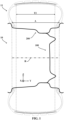
- a reference X, Y, Z is shown corresponding to the usual axial (Y), radial (Z) and circumferential (X) directions respectively of a tire or a mounted assembly.
- the measurements are made on an unloaded and uninflated tire or on a section of the tire in a meridian plane.
- the mounted assembly 10 comprises a tire 11 and a mounting support 100 comprising a rim 200.
- the tire 11 is here inflated to a pressure ranging from 200 to 350 kPa, preferably from 250 to 330 kPa and here equal to 270 kPa.
- the tire 11 has a substantially toric shape around an axis of revolution R substantially parallel to the axial direction Y.
- the tire 11 is intended for a passenger vehicle.
- the tire 11 is shown in new condition, that is to say not having yet been driven.
- the tire 11 comprises two sidewalls 30 bearing a marking indicating the dimension of the tire 11, as well as a speed index and a speed code.
- the tire 11 has a nominal section width SW ranging from 205 to 315, preferably from 225 to 315, more preferably from 245 to 315 and here equal to 255.
- the tire 11 also has a nominal aspect ratio AR ranging from 25 to 55, preferably from 30 to 45 and here equal to 35.
- the tire 11 has a nominal rim diameter ranging from 17 to 23, preferably from 18 to 23 and here equal to 18.
- the marking also comprises a load index LI ranging from 98 to 116, such that LI ⁇ LI'+1 with LI' being the load index of an EXTRA LOAD tire having the same dimension according to the standard manual ETRTO 2019.
- a tire with a dimension 255/35R18 in its EXTRA LOAD version has a load index equal to 94 as indicated on page 36 of the Passenger Car Tyres - Tyres with Metric Designation section of the ETRTO 2019 standard manual.
- This load index equal to 98 corresponds to the load index of a HIGH LOAD CAPACITY tire of dimension 255/35R18 as indicated in the ETRTO 2021 manual.
- tire 11 is indeed of the HIGH LOAD CAPACITY type.
- the rim 200 of the mounted assembly 10 is the rim having a rim width code equal to the width code of the measuring rim for the tire dimension reduced by 0.5 and therefore here equal to 8.5.
- the rim 200 has a profile of type J and a rim width A according to the ETRTO 2019 standard manual. In this case, the profile of the rim 200 being of type 8.5 J, its rim width A expressed in mm is equal to 215.90 mm.
- the tire 11 comprises a crown 12 comprising a tread 14 intended to come into contact with a ground when rolling and a crown reinforcement 16 extending in the crown 12 in the circumferential direction X.
- the tire 11 also comprises a sealing layer 18 to an inflation gas being intended to delimit an internal cavity closed with the mounting support 100 of the tire 11 once the tire 11 is mounted on the mounting support 100.
- the crown reinforcement 16 comprises a working reinforcement 20 and a hoop reinforcement 22.
- the working reinforcement 16 comprises at least one working layer and here comprises two working layers comprising a radially inner working layer 24 arranged radially within a radially outer working layer 26. Of the two radially inner 24 and radially outer 26 layers, the axially narrower layer is the radially outer layer 26.
- the hoop reinforcement 22 comprises at least one hoop layer and here comprises a hoop layer 28.
- the crown reinforcement 16 is radially surmounted by the tread 14.
- the hoop reinforcement 22, here the hoop layer 28, is arranged radially outside the working reinforcement 20 and is therefore radially interposed between the working reinforcement 20 and the tread 14.
- the two sidewalls 30 extend the crown 12 radially inwards.
- the tire 11 further comprises two beads 32 radially inwards to the sidewalls 30.
- Each sidewall 30 connects each bead 32 to the crown 12.
- the tire 11 comprises a carcass reinforcement 34 anchored in each bead 32, in this case forming a winding around a circumferential reinforcing element, here a bead wire 33.
- the carcass reinforcement 34 extends radially in each sidewall 30 and axially in the crown 12, radially internal to the crown reinforcement 16.
- the crown reinforcement 16 is arranged radially between the tread 14 and the carcass reinforcement 34.
- the carcass reinforcement 34 comprises at least one carcass layer 36 and here a single carcass layer 36.
- the hoop reinforcement 22, here the hoop layer 28, is delimited axially by two axial edges 281, 282 and comprises one or more hoop wire reinforcement elements wound circumferentially helically between each axial edge 281, 282 in a main direction forming, with the circumferential direction X of the tire 10, an angle AF, in absolute value, less than or equal to 10°, preferably less than or equal to 7° and more preferably less than or equal to 5°.
- AF in absolute value, less than or equal to 10°, preferably less than or equal to 7° and more preferably less than or equal to 5°.
- AF -5°.
- Each radially inner 24 and radially outer 26 working layer is axially delimited by two axial edges respectively 241, 242, 261, 262 of each working layer 24, 26.
- the mounted assembly 10 is such that the tire 11 has radially rectified sidewalls.
- Each working layer 24, 26 comprises working wire reinforcement elements extending axially from one axial edge 241, 261 to the other axial edge 242, 262 of each working layer 24, 26 substantially parallel to each other in main directions forming with the circumferential direction X of the tire 10, angles AT1 and AT2 respectively of opposite orientations and in absolute value, strictly greater than 10°, preferably ranging from 15° to 50° and more preferably ranging from 20° to 35°.
- the single carcass layer 36 forms a wrap around each circumferential reinforcing element 33 of each bead 32 such that an axially inner portion 3611, 3621 of the first carcass layer 36 is arranged axially inside an axially outer portion 3612, 3622 of the first carcass layer 36 and such that each axial end 361, 362 of the first carcass layer 36 is arranged radially outside each circumferential reinforcing element 33.
- Each axial end 361, 362 of the single carcass layer 36 is arranged radially inside the equator E of the tire. More precisely, each axial end 361, 362 of the first carcass layer 36 is arranged at a radial distance RNC less than or equal to 30 mm from a radially inner end 331 of each circumferential reinforcing element 33 of each bead 32.
- RNC 23 mm.
- Each working layer 24, 26, hooping layer 28 and carcass layer 36 comprises a calendering matrix for the wire reinforcement elements of the corresponding layer.
- the calendering matrix is polymeric and more preferably elastomeric like those usually used in the field of tires.
- Each hoop wire reinforcement element typically comprises two multifilament strands, each multifilament strand being made up of a yarn of aliphatic polyamide monofilaments, here nylon with a count equal to 140 tex, these two multifilament strands being individually helical at 250 turns per meter in one direction and then helical together at 250 turns per meter in the opposite direction. These two strands multifilament strands are wound in a helix around each other.
- a hoop wire reinforcement element may be used comprising a multifilament strand made up of a yarn of aliphatic polyamide monofilaments, here nylon with a count equal to 140 tex and a multifilament strand made up of a yarn of aromatic polyamide monofilaments, here aramid with a count equal to 167 tex, these two multifilament strands being individually wound in a helix at 290 turns per meter in one direction and then wound in a helix together at 290 turns per meter in the opposite direction. These two multifilament strands are wound in a helix around each other.
- a hoop wire reinforcement element comprising two multifilament strands each consisting of a yarn of aromatic polyamide monofilaments, here aramid with a count equal to 330 tex and a multifilament strand consisting of a yarn of aliphatic polyamide monofilaments, here nylon with a count equal to 188 tex, each of the multifilament strands being individually helically wound at 270 turns per meter in one direction and then helically wound together at 270 turns per meter in the opposite direction. These three multifilament strands are wound helically around each other.
- the use of a high load leads to a reduction in the acceptable limit speed of the tire as well as a degradation of its behavior, for example its drift rigidity.
- one or more high modulus hoop wire reinforcement elements for example like those described in the last two variants above comprising one or more strands of aromatic polyamide, it is possible to increase the acceptable limit speed of the tire and improve the behavior, in particular its drift rigidity.
- Each working wire reinforcement element is an assembly 4.26 of four steel monofilaments and comprising an inner layer of two monofilaments and an outer layer of two monofilaments wound together in a helix around the inner layer at a pitch of 14.0 mm, for example in the S direction.
- Such an assembly 4.26 has a breaking force equal to 640 N, a diameter equal to 0.7 mm.
- Each steel monofilament has a diameter equal to 0.26 mm and a mechanical strength equal to 3250 MPa.
- each textile wire reinforcement element of the carcass 360 comprises an assembly of at least two multifilament strands 363, 364.
- Each multifilament strand 363, 364 is selected from a polyester multifilament strand, an aromatic polyamide multifilament strand and an aliphatic polyamide multifilament strand, preferably selected from a polyester multifilament strand and an aromatic polyamide multifilament strand.
- the assembly is selected from an assembly of two polyester multifilament strands and an assembly of a polyester multifilament strand and an aromatic polyamide multifilament strand and here consists of two PET multifilament strands, these two multifilament strands being individually helical at 270 turns per meter in one direction and then helical together at 270 turns per meter in the opposite direction.
- Each of these multifilament strands has a count equal to 334 tex so that the total count of the assembly is greater than or equal to 475 tex and here equal to 668 tex.
- a mounted assembly was simulated, comprising each tire described above mounted on a mounting stand comprising the measuring rim for the tire size and defined according to the ETRTO 2019 standard manual.
- a simulation of a rolling test similar to the load/speed performance test described in Annex VII of UNECE Regulation No. 30 was carried out, but under even more demanding conditions.
- tires of dimensions 255/35 R21 and 275/30 R20 were compared, not conforming to the invention and whose carcass reinforcement comprises two carcass layers.
- Each of these tires has a sidewall height H ⁇ 95.
- the maximum meridian curvature Cmax of the axially innermost carcass layer was measured when the tire was mounted on a rim with a rim width code equal to the width code of the measuring rim defined according to the ETRTO 2019 standard manual for the tire size reduced by 0.5.
- These mounted assemblies were simulated loaded to a load higher than that described in the load/speed performance test described in Annex VII of UNECE Regulation No. 30 and inflated to a pressure lower than the pressure recommended to carry the corresponding load.
- the maximum meridian curvature limit above which a relatively significant compression of the axially innermost carcass layer in the sidewall and an increase in energy dissipation was determined to be equal to 0.30 mm -1 .
- Table 2 255/35 R21 275/30 R20 H 89 83 Cmax 0.31 mm -1 0.39 mm -1
- the tension of each carcass wire reinforcement element is measured at the end of the single carcass layer.
- the maximum volumetric energy dissipation DRNJ of the calendering matrix of a portion of the single carcass layer located in the sidewall was noted, expressed in daN/mm2. These values were related to a relative value 100, different in absolute value from the relative value 100 of the first simulation, below which the energy dissipation is controlled and above which the energy dissipation is not sufficiently controlled. These values are gathered in Table 4 below. The NT mention means that the assembled assembly has not been tested.
- T2/A ratio makes it possible to control the energy dissipation in the portion of the single carcass layer located in the sidewall, even under a relatively high load and with a pressure lower than the pressure recommended to carry the corresponding load.
- T2 and/or A can be varied in order to obtain a T2/A ratio allowing the sidewalls to be rectified radially and thus reduce the stresses exerted on the carcass reinforcement.
- Figure 4 the result of a static crush test of a tire of size 255/35R18 identical to that described above but in which the T2/A ratio is equal to 1.05 (tire shown on the left) and the tire described above whose T2/A ratio is equal to 0.97 (tire shown on the right).
- the load applied to each tire is equal to 750 kg at a pressure of 250 kPa.
- the deflection of the left tire is much greater than the deflection of the right tire.
- the distance DR1 from the axis of rotation R to the ground of the left tire is less than the distance DR2 from the axis of rotation R to the ground of the right tire.
- the sidewalls of the right-hand tire are radially straighter than the sidewalls of the left-hand tire.
- This can be seen by comparing, at the same radial dimension of each sidewall, the distances DF1 and DF2 between the outer surface of the sidewall located opposite the contact patch and the plane SA perpendicular to the axis of rotation R of the tire and passing through the support face of the rim delimiting the axial width A of the rim.
- This can also be seen by comparing, at the same radial dimension of each sidewall located at the right of the contact patch, the distances DF1' and DF2' between the outer surface of the sidewall and the plane perpendicular SA. It can be seen that DF1>DF2 and that DF1'>DF2'.
Landscapes
- Engineering & Computer Science (AREA)
- Mechanical Engineering (AREA)
- Tires In General (AREA)
Applications Claiming Priority (2)
| Application Number | Priority Date | Filing Date | Title |
|---|---|---|---|
| FR2010356 | 2020-10-09 | ||
| PCT/FR2021/051744 WO2022074342A1 (fr) | 2020-10-09 | 2021-10-07 | Pneumatique comprenant une unique couche de carcasse |
Publications (2)
| Publication Number | Publication Date |
|---|---|
| EP4225590A1 EP4225590A1 (fr) | 2023-08-16 |
| EP4225590B1 true EP4225590B1 (fr) | 2025-04-23 |
Family
ID=74347225
Family Applications (1)
| Application Number | Title | Priority Date | Filing Date |
|---|---|---|---|
| EP21801594.9A Active EP4225590B1 (fr) | 2020-10-09 | 2021-10-07 | Pneumatique comprenant une unique couche de carcasse |
Country Status (6)
| Country | Link |
|---|---|
| US (1) | US20230415518A1 (https=) |
| EP (1) | EP4225590B1 (https=) |
| JP (1) | JP2023544389A (https=) |
| KR (1) | KR20230080418A (https=) |
| CN (1) | CN116171229A (https=) |
| WO (1) | WO2022074342A1 (https=) |
Families Citing this family (13)
| Publication number | Priority date | Publication date | Assignee | Title |
|---|---|---|---|---|
| WO2022050153A1 (ja) * | 2020-09-04 | 2022-03-10 | 住友ゴム工業株式会社 | 空気入りタイヤ |
| FR3144773B1 (fr) | 2023-01-11 | 2024-11-29 | Michelin & Cie | Pneumatique à interface améliorée |
| EP4570486A1 (de) * | 2023-12-14 | 2025-06-18 | Continental Reifen Deutschland GmbH | Fahrzeugluftreifen |
| DE102024209701A1 (de) | 2024-10-02 | 2026-04-02 | Continental Reifen Deutschland Gmbh | Fahrzeugluftreifen |
| DE102024209696A1 (de) | 2024-10-02 | 2026-04-02 | Continental Reifen Deutschland Gmbh | Fahrzeugluftreifen |
| DE102024209699A1 (de) | 2024-10-02 | 2026-04-02 | Continental Reifen Deutschland Gmbh | Fahrzeugluftreifen und Verfahren zum Herstellen eines Fahrzeugluftreifens |
| DE102024209702A1 (de) | 2024-10-02 | 2026-04-02 | Continental Reifen Deutschland Gmbh | Reifenrohling und Verfahren zum Herstellen eines Fahrzeugluftreifens |
| DE102024209706A1 (de) | 2024-10-02 | 2026-04-02 | Continental Reifen Deutschland Gmbh | Verfahren zum Herstellen eines Fahrzeugluftreifens |
| DE102024209704A1 (de) | 2024-10-02 | 2026-04-02 | Continental Reifen Deutschland Gmbh | Fahrzeugluftreifen |
| DE102024209707A1 (de) | 2024-10-02 | 2026-04-02 | Continental Reifen Deutschland Gmbh | Fahrzeugluftreifen |
| DE102024209705A1 (de) | 2024-10-02 | 2026-04-02 | Continental Reifen Deutschland Gmbh | Fahrzeugluftreifen |
| DE102024209703A1 (de) | 2024-10-02 | 2026-04-02 | Continental Reifen Deutschland Gmbh | Fahrzeugluftreifen |
| DE102024209709A1 (de) | 2024-10-02 | 2026-04-02 | Continental Reifen Deutschland Gmbh | Fahrzeugluftreifen |
Family Cites Families (19)
| Publication number | Priority date | Publication date | Assignee | Title |
|---|---|---|---|---|
| FR2499475A1 (fr) * | 1981-02-12 | 1982-08-13 | Michelin & Cie | Pneumatique gros porteur dont l'armature de sommet comporte des cables circonferentiels thermoretractables, et son procede de fabrication |
| JP3087074B2 (ja) * | 1990-06-22 | 2000-09-11 | 横浜ゴム株式会社 | 乗用車用空気入りタイヤ |
| DE69708510T2 (de) * | 1996-06-11 | 2002-05-16 | Bridgestone Corp., Tokio/Tokyo | Radiale Luftreifen |
| JPH1087898A (ja) * | 1996-07-23 | 1998-04-07 | Bridgestone Corp | 空気入りタイヤ |
| US6491076B1 (en) * | 2000-06-13 | 2002-12-10 | The Goodyear Tire & Rubber Company | Triangular bead configuration for pneumatic tire with extended load carrying capacity |
| US6443201B1 (en) * | 2000-06-13 | 2002-09-03 | The Goodyear Tire & Rubber Company | Pneumatic tire with extended load carrying capacity |
| FR2870164B1 (fr) | 2004-05-12 | 2006-07-14 | Michelin Soc Tech | Pneumatique et composite metal/caoutchouc pour pneumatique |
| FR2986741B1 (fr) * | 2012-02-10 | 2014-03-07 | Michelin & Cie | Pneumatique allege renforce. |
| FR2993501B1 (fr) * | 2012-07-20 | 2014-08-08 | Michelin & Cie | Pneumatique optimise. |
| JP6074230B2 (ja) * | 2012-11-09 | 2017-02-01 | 住友ゴム工業株式会社 | 空気入りタイヤ、及びその製造方法 |
| JP6208438B2 (ja) * | 2013-02-28 | 2017-10-04 | 株式会社ブリヂストン | 空気入り安全タイヤ |
| FR3035025B1 (fr) * | 2015-04-17 | 2017-03-31 | Michelin & Cie | Armature de renforcement de pneumatique |
| FR3056215A1 (fr) * | 2016-09-19 | 2018-03-23 | Compagnie Generale Des Etablissements Michelin | Composite d’elastomere et pneumatique comprenant ce composite |
| GB201717883D0 (en) * | 2017-10-31 | 2017-12-13 | Dyson Technology Ltd | Electric motor vehicle |
| WO2019180352A1 (fr) * | 2018-03-20 | 2019-09-26 | Compagnie Generale Des Etablissements Michelin | Pneumatique comprenant une unique nappe de carcasse avec une profondeur de déformation dans le flanc améliorée après rodage |
| JP7063161B2 (ja) * | 2018-07-17 | 2022-05-09 | 住友ゴム工業株式会社 | 空気入りタイヤ |
| WO2020025685A1 (fr) * | 2018-08-03 | 2020-02-06 | Compagnie Generale Des Etablissements Michelin | Pneumatique à architecture sommet optimisée |
| FR3105097A1 (fr) | 2019-12-19 | 2021-06-25 | Compagnie Generale Des Etablissements Michelin | Pneumatique comprenant un bourrelet perfectionné |
| KR20230084164A (ko) * | 2020-10-09 | 2023-06-12 | 꽁빠니 제네날 드 에따블리세망 미쉘린 | 2개의 카카스 층을 포함하는 타이어 |
-
2021
- 2021-10-07 CN CN202180062563.1A patent/CN116171229A/zh active Pending
- 2021-10-07 EP EP21801594.9A patent/EP4225590B1/fr active Active
- 2021-10-07 US US18/030,670 patent/US20230415518A1/en active Pending
- 2021-10-07 JP JP2023520317A patent/JP2023544389A/ja active Pending
- 2021-10-07 KR KR1020237011689A patent/KR20230080418A/ko active Pending
- 2021-10-07 WO PCT/FR2021/051744 patent/WO2022074342A1/fr not_active Ceased
Also Published As
| Publication number | Publication date |
|---|---|
| KR20230080418A (ko) | 2023-06-07 |
| CN116171229A (zh) | 2023-05-26 |
| US20230415518A1 (en) | 2023-12-28 |
| WO2022074342A1 (fr) | 2022-04-14 |
| JP2023544389A (ja) | 2023-10-23 |
| EP4225590A1 (fr) | 2023-08-16 |
Similar Documents
| Publication | Publication Date | Title |
|---|---|---|
| EP4225590B1 (fr) | Pneumatique comprenant une unique couche de carcasse | |
| WO2022074341A1 (fr) | Ensemble monte comprenant un pneumatique | |
| EP4225589B1 (fr) | Pneumatique pour jante mini | |
| EP3768526B1 (fr) | Pneumatique comprenant une unique nappe de carcasse avec une profondeur de déformation dans le flanc améliorée après rodage | |
| EP4045337B1 (fr) | Pneumatique a faible resistance au roulement et son procede de fabrication | |
| WO2014057082A1 (fr) | Pneumatique adapté pour un roulage à plat comprenant nappe de carcasse hybride | |
| EP3515727B1 (fr) | Composite d'élastomère et pneumatique comprenant ce composite | |
| WO2018051032A1 (fr) | Élément de renfort, composite d'élastomère et pneumatique comprenant cet élément de renfort | |
| WO2022074343A1 (fr) | Pneumatique comprenant deux couches de carcasse | |
| EP3853045B1 (fr) | Pneumatique comportant une armature de carcasse formee d'une unique couche d'elements de renforcement textiles | |
| FR3144773A1 (fr) | Pneumatique à interface améliorée | |
| EP4504526B1 (fr) | Pneumatique à haute capacité de chargement comprenant un insert de rigidification de flanc | |
| EP4100265A1 (fr) | Pneumatique pour véhicule agricole comprenant une armature de carcasse monocouche | |
| EP3880492B1 (fr) | Pneumatique pour véhicule à deux roues comprenant un renfort de frettage hybride | |
| EP4504531A1 (fr) | Pneumatique à haute capacité de charge surveillé en pression |
Legal Events
| Date | Code | Title | Description |
|---|---|---|---|
| STAA | Information on the status of an ep patent application or granted ep patent |
Free format text: STATUS: UNKNOWN |
|
| STAA | Information on the status of an ep patent application or granted ep patent |
Free format text: STATUS: THE INTERNATIONAL PUBLICATION HAS BEEN MADE |
|
| TPAC | Observations filed by third parties |
Free format text: ORIGINAL CODE: EPIDOSNTIPA |
|
| PUAI | Public reference made under article 153(3) epc to a published international application that has entered the european phase |
Free format text: ORIGINAL CODE: 0009012 |
|
| STAA | Information on the status of an ep patent application or granted ep patent |
Free format text: STATUS: REQUEST FOR EXAMINATION WAS MADE |
|
| 17P | Request for examination filed |
Effective date: 20230509 |
|
| AK | Designated contracting states |
Kind code of ref document: A1 Designated state(s): AL AT BE BG CH CY CZ DE DK EE ES FI FR GB GR HR HU IE IS IT LI LT LU LV MC MK MT NL NO PL PT RO RS SE SI SK SM TR |
|
| DAV | Request for validation of the european patent (deleted) | ||
| DAX | Request for extension of the european patent (deleted) | ||
| GRAP | Despatch of communication of intention to grant a patent |
Free format text: ORIGINAL CODE: EPIDOSNIGR1 |
|
| STAA | Information on the status of an ep patent application or granted ep patent |
Free format text: STATUS: GRANT OF PATENT IS INTENDED |
|
| RIC1 | Information provided on ipc code assigned before grant |
Ipc: B60C 9/04 20060101ALN20241129BHEP Ipc: B60C 9/13 20060101ALI20241129BHEP Ipc: B60C 9/08 20060101ALI20241129BHEP Ipc: B60C 9/18 20060101AFI20241129BHEP |
|
| INTG | Intention to grant announced |
Effective date: 20241212 |
|
| RIN1 | Information on inventor provided before grant (corrected) |
Inventor name: MOUREAU, PIERRE Inventor name: GUIMARD, BRUNO Inventor name: DUCHEMIN, SYLVIE |
|
| GRAJ | Information related to disapproval of communication of intention to grant by the applicant or resumption of examination proceedings by the epo deleted |
Free format text: ORIGINAL CODE: EPIDOSDIGR1 |
|
| STAA | Information on the status of an ep patent application or granted ep patent |
Free format text: STATUS: REQUEST FOR EXAMINATION WAS MADE |
|
| GRAP | Despatch of communication of intention to grant a patent |
Free format text: ORIGINAL CODE: EPIDOSNIGR1 |
|
| STAA | Information on the status of an ep patent application or granted ep patent |
Free format text: STATUS: GRANT OF PATENT IS INTENDED |
|
| INTC | Intention to grant announced (deleted) | ||
| RIC1 | Information provided on ipc code assigned before grant |
Ipc: B60C 9/04 20060101ALN20250206BHEP Ipc: B60C 9/13 20060101ALI20250206BHEP Ipc: B60C 9/08 20060101ALI20250206BHEP Ipc: B60C 9/18 20060101AFI20250206BHEP |
|
| GRAS | Grant fee paid |
Free format text: ORIGINAL CODE: EPIDOSNIGR3 |
|
| GRAA | (expected) grant |
Free format text: ORIGINAL CODE: 0009210 |
|
| STAA | Information on the status of an ep patent application or granted ep patent |
Free format text: STATUS: THE PATENT HAS BEEN GRANTED |
|
| INTG | Intention to grant announced |
Effective date: 20250219 |
|
| AK | Designated contracting states |
Kind code of ref document: B1 Designated state(s): AL AT BE BG CH CY CZ DE DK EE ES FI FR GB GR HR HU IE IS IT LI LT LU LV MC MK MT NL NO PL PT RO RS SE SI SK SM TR |
|
| REG | Reference to a national code |
Ref country code: GB Ref legal event code: FG4D Free format text: NOT ENGLISH |
|
| REG | Reference to a national code |
Ref country code: CH Ref legal event code: EP |
|
| REG | Reference to a national code |
Ref country code: DE Ref legal event code: R096 Ref document number: 602021029697 Country of ref document: DE |
|
| REG | Reference to a national code |
Ref country code: IE Ref legal event code: FG4D Free format text: LANGUAGE OF EP DOCUMENT: FRENCH |
|
| PG25 | Lapsed in a contracting state [announced via postgrant information from national office to epo] |
Ref country code: NL Free format text: LAPSE BECAUSE OF FAILURE TO SUBMIT A TRANSLATION OF THE DESCRIPTION OR TO PAY THE FEE WITHIN THE PRESCRIBED TIME-LIMIT Effective date: 20250423 |
|
| REG | Reference to a national code |
Ref country code: AT Ref legal event code: MK05 Ref document number: 1787443 Country of ref document: AT Kind code of ref document: T Effective date: 20250423 |
|
| PG25 | Lapsed in a contracting state [announced via postgrant information from national office to epo] |
Ref country code: FI Free format text: LAPSE BECAUSE OF FAILURE TO SUBMIT A TRANSLATION OF THE DESCRIPTION OR TO PAY THE FEE WITHIN THE PRESCRIBED TIME-LIMIT Effective date: 20250423 Ref country code: ES Free format text: LAPSE BECAUSE OF FAILURE TO SUBMIT A TRANSLATION OF THE DESCRIPTION OR TO PAY THE FEE WITHIN THE PRESCRIBED TIME-LIMIT Effective date: 20250423 Ref country code: PT Free format text: LAPSE BECAUSE OF FAILURE TO SUBMIT A TRANSLATION OF THE DESCRIPTION OR TO PAY THE FEE WITHIN THE PRESCRIBED TIME-LIMIT Effective date: 20250825 |
|
| REG | Reference to a national code |
Ref country code: LT Ref legal event code: MG9D |
|
| PG25 | Lapsed in a contracting state [announced via postgrant information from national office to epo] |
Ref country code: GR Free format text: LAPSE BECAUSE OF FAILURE TO SUBMIT A TRANSLATION OF THE DESCRIPTION OR TO PAY THE FEE WITHIN THE PRESCRIBED TIME-LIMIT Effective date: 20250724 Ref country code: NO Free format text: LAPSE BECAUSE OF FAILURE TO SUBMIT A TRANSLATION OF THE DESCRIPTION OR TO PAY THE FEE WITHIN THE PRESCRIBED TIME-LIMIT Effective date: 20250723 |
|
| PG25 | Lapsed in a contracting state [announced via postgrant information from national office to epo] |
Ref country code: PL Free format text: LAPSE BECAUSE OF FAILURE TO SUBMIT A TRANSLATION OF THE DESCRIPTION OR TO PAY THE FEE WITHIN THE PRESCRIBED TIME-LIMIT Effective date: 20250423 |
|
| PG25 | Lapsed in a contracting state [announced via postgrant information from national office to epo] |
Ref country code: BG Free format text: LAPSE BECAUSE OF FAILURE TO SUBMIT A TRANSLATION OF THE DESCRIPTION OR TO PAY THE FEE WITHIN THE PRESCRIBED TIME-LIMIT Effective date: 20250423 |
|
| PG25 | Lapsed in a contracting state [announced via postgrant information from national office to epo] |
Ref country code: HR Free format text: LAPSE BECAUSE OF FAILURE TO SUBMIT A TRANSLATION OF THE DESCRIPTION OR TO PAY THE FEE WITHIN THE PRESCRIBED TIME-LIMIT Effective date: 20250423 |
|
| PG25 | Lapsed in a contracting state [announced via postgrant information from national office to epo] |
Ref country code: AT Free format text: LAPSE BECAUSE OF FAILURE TO SUBMIT A TRANSLATION OF THE DESCRIPTION OR TO PAY THE FEE WITHIN THE PRESCRIBED TIME-LIMIT Effective date: 20250423 |
|
| PG25 | Lapsed in a contracting state [announced via postgrant information from national office to epo] |
Ref country code: RS Free format text: LAPSE BECAUSE OF FAILURE TO SUBMIT A TRANSLATION OF THE DESCRIPTION OR TO PAY THE FEE WITHIN THE PRESCRIBED TIME-LIMIT Effective date: 20250723 |
|
| PG25 | Lapsed in a contracting state [announced via postgrant information from national office to epo] |
Ref country code: IS Free format text: LAPSE BECAUSE OF FAILURE TO SUBMIT A TRANSLATION OF THE DESCRIPTION OR TO PAY THE FEE WITHIN THE PRESCRIBED TIME-LIMIT Effective date: 20250823 |
|
| PG25 | Lapsed in a contracting state [announced via postgrant information from national office to epo] |
Ref country code: LV Free format text: LAPSE BECAUSE OF FAILURE TO SUBMIT A TRANSLATION OF THE DESCRIPTION OR TO PAY THE FEE WITHIN THE PRESCRIBED TIME-LIMIT Effective date: 20250423 |
|
| PGFP | Annual fee paid to national office [announced via postgrant information from national office to epo] |
Ref country code: DE Payment date: 20251021 Year of fee payment: 5 |
|
| PG25 | Lapsed in a contracting state [announced via postgrant information from national office to epo] |
Ref country code: SM Free format text: LAPSE BECAUSE OF FAILURE TO SUBMIT A TRANSLATION OF THE DESCRIPTION OR TO PAY THE FEE WITHIN THE PRESCRIBED TIME-LIMIT Effective date: 20250423 Ref country code: DK Free format text: LAPSE BECAUSE OF FAILURE TO SUBMIT A TRANSLATION OF THE DESCRIPTION OR TO PAY THE FEE WITHIN THE PRESCRIBED TIME-LIMIT Effective date: 20250423 |
|
| PGFP | Annual fee paid to national office [announced via postgrant information from national office to epo] |
Ref country code: FR Payment date: 20251030 Year of fee payment: 5 |
|
| PG25 | Lapsed in a contracting state [announced via postgrant information from national office to epo] |
Ref country code: CZ Free format text: LAPSE BECAUSE OF FAILURE TO SUBMIT A TRANSLATION OF THE DESCRIPTION OR TO PAY THE FEE WITHIN THE PRESCRIBED TIME-LIMIT Effective date: 20250423 |
|
| PG25 | Lapsed in a contracting state [announced via postgrant information from national office to epo] |
Ref country code: EE Free format text: LAPSE BECAUSE OF FAILURE TO SUBMIT A TRANSLATION OF THE DESCRIPTION OR TO PAY THE FEE WITHIN THE PRESCRIBED TIME-LIMIT Effective date: 20250423 |
|
| REG | Reference to a national code |
Ref country code: DE Ref legal event code: R097 Ref document number: 602021029697 Country of ref document: DE |
|
| PG25 | Lapsed in a contracting state [announced via postgrant information from national office to epo] |
Ref country code: SK Free format text: LAPSE BECAUSE OF FAILURE TO SUBMIT A TRANSLATION OF THE DESCRIPTION OR TO PAY THE FEE WITHIN THE PRESCRIBED TIME-LIMIT Effective date: 20250423 |
|
| PG25 | Lapsed in a contracting state [announced via postgrant information from national office to epo] |
Ref country code: IT Free format text: LAPSE BECAUSE OF FAILURE TO SUBMIT A TRANSLATION OF THE DESCRIPTION OR TO PAY THE FEE WITHIN THE PRESCRIBED TIME-LIMIT Effective date: 20250423 |
|
| PLBE | No opposition filed within time limit |
Free format text: ORIGINAL CODE: 0009261 |
|
| STAA | Information on the status of an ep patent application or granted ep patent |
Free format text: STATUS: NO OPPOSITION FILED WITHIN TIME LIMIT |
|
| REG | Reference to a national code |
Ref country code: CH Ref legal event code: L10 Free format text: ST27 STATUS EVENT CODE: U-0-0-L10-L00 (AS PROVIDED BY THE NATIONAL OFFICE) Effective date: 20260304 |
|
| PG25 | Lapsed in a contracting state [announced via postgrant information from national office to epo] |
Ref country code: RO Free format text: LAPSE BECAUSE OF FAILURE TO SUBMIT A TRANSLATION OF THE DESCRIPTION OR TO PAY THE FEE WITHIN THE PRESCRIBED TIME-LIMIT Effective date: 20250423 |
|
| 26N | No opposition filed |
Effective date: 20260126 |