EP4225573B1 - Uv schutzfolie für den aussenbereich - Google Patents
Uv schutzfolie für den aussenbereich Download PDFInfo
- Publication number
- EP4225573B1 EP4225573B1 EP21798295.8A EP21798295A EP4225573B1 EP 4225573 B1 EP4225573 B1 EP 4225573B1 EP 21798295 A EP21798295 A EP 21798295A EP 4225573 B1 EP4225573 B1 EP 4225573B1
- Authority
- EP
- European Patent Office
- Prior art keywords
- base film
- melt coating
- hot melt
- lacquer
- protective film
- Prior art date
- Legal status (The legal status is an assumption and is not a legal conclusion. Google has not performed a legal analysis and makes no representation as to the accuracy of the status listed.)
- Active
Links
Images

Classifications
-
- B—PERFORMING OPERATIONS; TRANSPORTING
- B32—LAYERED PRODUCTS
- B32B—LAYERED PRODUCTS, i.e. PRODUCTS BUILT-UP OF STRATA OF FLAT OR NON-FLAT, e.g. CELLULAR OR HONEYCOMB, FORM
- B32B3/00—Layered products comprising a layer with external or internal discontinuities or unevennesses, or a layer of non-planar shape; Layered products comprising a layer having particular features of form
- B32B3/26—Layered products comprising a layer with external or internal discontinuities or unevennesses, or a layer of non-planar shape; Layered products comprising a layer having particular features of form characterised by a particular shape of the outline of the cross-section of a continuous layer; characterised by a layer with cavities or internal voids ; characterised by an apertured layer
- B32B3/263—Layered products comprising a layer with external or internal discontinuities or unevennesses, or a layer of non-planar shape; Layered products comprising a layer having particular features of form characterised by a particular shape of the outline of the cross-section of a continuous layer; characterised by a layer with cavities or internal voids ; characterised by an apertured layer characterised by a layer having non-uniform thickness
-
- B—PERFORMING OPERATIONS; TRANSPORTING
- B32—LAYERED PRODUCTS
- B32B—LAYERED PRODUCTS, i.e. PRODUCTS BUILT-UP OF STRATA OF FLAT OR NON-FLAT, e.g. CELLULAR OR HONEYCOMB, FORM
- B32B15/00—Layered products comprising a layer of metal
- B32B15/04—Layered products comprising a layer of metal comprising metal as the main or only constituent of a layer, which is next to another layer of the same or of a different material
- B32B15/08—Layered products comprising a layer of metal comprising metal as the main or only constituent of a layer, which is next to another layer of the same or of a different material of synthetic resin
- B32B15/082—Layered products comprising a layer of metal comprising metal as the main or only constituent of a layer, which is next to another layer of the same or of a different material of synthetic resin comprising vinyl resins; comprising acrylic resins
-
- B—PERFORMING OPERATIONS; TRANSPORTING
- B32—LAYERED PRODUCTS
- B32B—LAYERED PRODUCTS, i.e. PRODUCTS BUILT-UP OF STRATA OF FLAT OR NON-FLAT, e.g. CELLULAR OR HONEYCOMB, FORM
- B32B15/00—Layered products comprising a layer of metal
- B32B15/04—Layered products comprising a layer of metal comprising metal as the main or only constituent of a layer, which is next to another layer of the same or of a different material
- B32B15/08—Layered products comprising a layer of metal comprising metal as the main or only constituent of a layer, which is next to another layer of the same or of a different material of synthetic resin
- B32B15/085—Layered products comprising a layer of metal comprising metal as the main or only constituent of a layer, which is next to another layer of the same or of a different material of synthetic resin comprising polyolefins
-
- B—PERFORMING OPERATIONS; TRANSPORTING
- B32—LAYERED PRODUCTS
- B32B—LAYERED PRODUCTS, i.e. PRODUCTS BUILT-UP OF STRATA OF FLAT OR NON-FLAT, e.g. CELLULAR OR HONEYCOMB, FORM
- B32B15/00—Layered products comprising a layer of metal
- B32B15/04—Layered products comprising a layer of metal comprising metal as the main or only constituent of a layer, which is next to another layer of the same or of a different material
- B32B15/08—Layered products comprising a layer of metal comprising metal as the main or only constituent of a layer, which is next to another layer of the same or of a different material of synthetic resin
- B32B15/095—Layered products comprising a layer of metal comprising metal as the main or only constituent of a layer, which is next to another layer of the same or of a different material of synthetic resin comprising polyurethanes
-
- B—PERFORMING OPERATIONS; TRANSPORTING
- B32—LAYERED PRODUCTS
- B32B—LAYERED PRODUCTS, i.e. PRODUCTS BUILT-UP OF STRATA OF FLAT OR NON-FLAT, e.g. CELLULAR OR HONEYCOMB, FORM
- B32B21/00—Layered products comprising a layer of wood, e.g. wood board, veneer, wood particle board
- B32B21/04—Layered products comprising a layer of wood, e.g. wood board, veneer, wood particle board comprising wood as the main or only constituent of a layer, which is next to another layer of the same or of a different material
- B32B21/08—Layered products comprising a layer of wood, e.g. wood board, veneer, wood particle board comprising wood as the main or only constituent of a layer, which is next to another layer of the same or of a different material of synthetic resin
-
- B—PERFORMING OPERATIONS; TRANSPORTING
- B32—LAYERED PRODUCTS
- B32B—LAYERED PRODUCTS, i.e. PRODUCTS BUILT-UP OF STRATA OF FLAT OR NON-FLAT, e.g. CELLULAR OR HONEYCOMB, FORM
- B32B27/00—Layered products comprising a layer of synthetic resin
- B32B27/06—Layered products comprising a layer of synthetic resin as the main or only constituent of a layer, which is next to another layer of the same or of a different material
- B32B27/08—Layered products comprising a layer of synthetic resin as the main or only constituent of a layer, which is next to another layer of the same or of a different material of synthetic resin
-
- B—PERFORMING OPERATIONS; TRANSPORTING
- B32—LAYERED PRODUCTS
- B32B—LAYERED PRODUCTS, i.e. PRODUCTS BUILT-UP OF STRATA OF FLAT OR NON-FLAT, e.g. CELLULAR OR HONEYCOMB, FORM
- B32B27/00—Layered products comprising a layer of synthetic resin
- B32B27/18—Layered products comprising a layer of synthetic resin characterised by the use of special additives
- B32B27/20—Layered products comprising a layer of synthetic resin characterised by the use of special additives using fillers, pigments, thixotroping agents
-
- B—PERFORMING OPERATIONS; TRANSPORTING
- B32—LAYERED PRODUCTS
- B32B—LAYERED PRODUCTS, i.e. PRODUCTS BUILT-UP OF STRATA OF FLAT OR NON-FLAT, e.g. CELLULAR OR HONEYCOMB, FORM
- B32B27/00—Layered products comprising a layer of synthetic resin
- B32B27/30—Layered products comprising a layer of synthetic resin comprising vinyl (co)polymers; comprising acrylic (co)polymers
- B32B27/304—Layered products comprising a layer of synthetic resin comprising vinyl (co)polymers; comprising acrylic (co)polymers comprising vinyl halide (co)polymers, e.g. PVC, PVDC, PVF, PVDF
-
- B—PERFORMING OPERATIONS; TRANSPORTING
- B32—LAYERED PRODUCTS
- B32B—LAYERED PRODUCTS, i.e. PRODUCTS BUILT-UP OF STRATA OF FLAT OR NON-FLAT, e.g. CELLULAR OR HONEYCOMB, FORM
- B32B27/00—Layered products comprising a layer of synthetic resin
- B32B27/30—Layered products comprising a layer of synthetic resin comprising vinyl (co)polymers; comprising acrylic (co)polymers
- B32B27/308—Layered products comprising a layer of synthetic resin comprising vinyl (co)polymers; comprising acrylic (co)polymers comprising acrylic (co)polymers
-
- B—PERFORMING OPERATIONS; TRANSPORTING
- B32—LAYERED PRODUCTS
- B32B—LAYERED PRODUCTS, i.e. PRODUCTS BUILT-UP OF STRATA OF FLAT OR NON-FLAT, e.g. CELLULAR OR HONEYCOMB, FORM
- B32B27/00—Layered products comprising a layer of synthetic resin
- B32B27/32—Layered products comprising a layer of synthetic resin comprising polyolefins
-
- B—PERFORMING OPERATIONS; TRANSPORTING
- B32—LAYERED PRODUCTS
- B32B—LAYERED PRODUCTS, i.e. PRODUCTS BUILT-UP OF STRATA OF FLAT OR NON-FLAT, e.g. CELLULAR OR HONEYCOMB, FORM
- B32B27/00—Layered products comprising a layer of synthetic resin
- B32B27/40—Layered products comprising a layer of synthetic resin comprising polyurethanes
-
- B—PERFORMING OPERATIONS; TRANSPORTING
- B32—LAYERED PRODUCTS
- B32B—LAYERED PRODUCTS, i.e. PRODUCTS BUILT-UP OF STRATA OF FLAT OR NON-FLAT, e.g. CELLULAR OR HONEYCOMB, FORM
- B32B3/00—Layered products comprising a layer with external or internal discontinuities or unevennesses, or a layer of non-planar shape; Layered products comprising a layer having particular features of form
- B32B3/26—Layered products comprising a layer with external or internal discontinuities or unevennesses, or a layer of non-planar shape; Layered products comprising a layer having particular features of form characterised by a particular shape of the outline of the cross-section of a continuous layer; characterised by a layer with cavities or internal voids ; characterised by an apertured layer
- B32B3/30—Layered products comprising a layer with external or internal discontinuities or unevennesses, or a layer of non-planar shape; Layered products comprising a layer having particular features of form characterised by a particular shape of the outline of the cross-section of a continuous layer; characterised by a layer with cavities or internal voids ; characterised by an apertured layer characterised by a layer formed with recesses or projections, e.g. hollows, grooves, protuberances, ribs
-
- B—PERFORMING OPERATIONS; TRANSPORTING
- B32—LAYERED PRODUCTS
- B32B—LAYERED PRODUCTS, i.e. PRODUCTS BUILT-UP OF STRATA OF FLAT OR NON-FLAT, e.g. CELLULAR OR HONEYCOMB, FORM
- B32B7/00—Layered products characterised by the relation between layers; Layered products characterised by the relative orientation of features between layers, or by the relative values of a measurable parameter between layers, i.e. products comprising layers having different physical, chemical or physicochemical properties; Layered products characterised by the interconnection of layers
- B32B7/04—Interconnection of layers
- B32B7/12—Interconnection of layers using interposed adhesives or interposed materials with bonding properties
-
- B—PERFORMING OPERATIONS; TRANSPORTING
- B32—LAYERED PRODUCTS
- B32B—LAYERED PRODUCTS, i.e. PRODUCTS BUILT-UP OF STRATA OF FLAT OR NON-FLAT, e.g. CELLULAR OR HONEYCOMB, FORM
- B32B2255/00—Coating on the layer surface
- B32B2255/10—Coating on the layer surface on synthetic resin layer or on natural or synthetic rubber layer
-
- B—PERFORMING OPERATIONS; TRANSPORTING
- B32—LAYERED PRODUCTS
- B32B—LAYERED PRODUCTS, i.e. PRODUCTS BUILT-UP OF STRATA OF FLAT OR NON-FLAT, e.g. CELLULAR OR HONEYCOMB, FORM
- B32B2255/00—Coating on the layer surface
- B32B2255/26—Polymeric coating
-
- B—PERFORMING OPERATIONS; TRANSPORTING
- B32—LAYERED PRODUCTS
- B32B—LAYERED PRODUCTS, i.e. PRODUCTS BUILT-UP OF STRATA OF FLAT OR NON-FLAT, e.g. CELLULAR OR HONEYCOMB, FORM
- B32B2255/00—Coating on the layer surface
- B32B2255/28—Multiple coating on one surface
-
- B—PERFORMING OPERATIONS; TRANSPORTING
- B32—LAYERED PRODUCTS
- B32B—LAYERED PRODUCTS, i.e. PRODUCTS BUILT-UP OF STRATA OF FLAT OR NON-FLAT, e.g. CELLULAR OR HONEYCOMB, FORM
- B32B2264/00—Composition or properties of particles which form a particulate layer or are present as additives
- B32B2264/10—Inorganic particles
- B32B2264/101—Glass
-
- B—PERFORMING OPERATIONS; TRANSPORTING
- B32—LAYERED PRODUCTS
- B32B—LAYERED PRODUCTS, i.e. PRODUCTS BUILT-UP OF STRATA OF FLAT OR NON-FLAT, e.g. CELLULAR OR HONEYCOMB, FORM
- B32B2264/00—Composition or properties of particles which form a particulate layer or are present as additives
- B32B2264/10—Inorganic particles
- B32B2264/102—Oxide or hydroxide
- B32B2264/1023—Alumina
-
- B—PERFORMING OPERATIONS; TRANSPORTING
- B32—LAYERED PRODUCTS
- B32B—LAYERED PRODUCTS, i.e. PRODUCTS BUILT-UP OF STRATA OF FLAT OR NON-FLAT, e.g. CELLULAR OR HONEYCOMB, FORM
- B32B2307/00—Properties of the layers or laminate
- B32B2307/40—Properties of the layers or laminate having particular optical properties
- B32B2307/402—Coloured
- B32B2307/4023—Coloured on the layer surface, e.g. ink
-
- B—PERFORMING OPERATIONS; TRANSPORTING
- B32—LAYERED PRODUCTS
- B32B—LAYERED PRODUCTS, i.e. PRODUCTS BUILT-UP OF STRATA OF FLAT OR NON-FLAT, e.g. CELLULAR OR HONEYCOMB, FORM
- B32B2307/00—Properties of the layers or laminate
- B32B2307/40—Properties of the layers or laminate having particular optical properties
- B32B2307/402—Coloured
- B32B2307/4026—Coloured within the layer by addition of a colorant, e.g. pigments, dyes
-
- B—PERFORMING OPERATIONS; TRANSPORTING
- B32—LAYERED PRODUCTS
- B32B—LAYERED PRODUCTS, i.e. PRODUCTS BUILT-UP OF STRATA OF FLAT OR NON-FLAT, e.g. CELLULAR OR HONEYCOMB, FORM
- B32B2307/00—Properties of the layers or laminate
- B32B2307/40—Properties of the layers or laminate having particular optical properties
- B32B2307/412—Transparent
-
- B—PERFORMING OPERATIONS; TRANSPORTING
- B32—LAYERED PRODUCTS
- B32B—LAYERED PRODUCTS, i.e. PRODUCTS BUILT-UP OF STRATA OF FLAT OR NON-FLAT, e.g. CELLULAR OR HONEYCOMB, FORM
- B32B2307/00—Properties of the layers or laminate
- B32B2307/70—Other properties
- B32B2307/71—Resistive to light or to UV
-
- B—PERFORMING OPERATIONS; TRANSPORTING
- B32—LAYERED PRODUCTS
- B32B—LAYERED PRODUCTS, i.e. PRODUCTS BUILT-UP OF STRATA OF FLAT OR NON-FLAT, e.g. CELLULAR OR HONEYCOMB, FORM
- B32B2307/00—Properties of the layers or laminate
- B32B2307/70—Other properties
- B32B2307/732—Dimensional properties
-
- B—PERFORMING OPERATIONS; TRANSPORTING
- B32—LAYERED PRODUCTS
- B32B—LAYERED PRODUCTS, i.e. PRODUCTS BUILT-UP OF STRATA OF FLAT OR NON-FLAT, e.g. CELLULAR OR HONEYCOMB, FORM
- B32B2307/00—Properties of the layers or laminate
- B32B2307/70—Other properties
- B32B2307/744—Non-slip, anti-slip
-
- B—PERFORMING OPERATIONS; TRANSPORTING
- B32—LAYERED PRODUCTS
- B32B—LAYERED PRODUCTS, i.e. PRODUCTS BUILT-UP OF STRATA OF FLAT OR NON-FLAT, e.g. CELLULAR OR HONEYCOMB, FORM
- B32B2419/00—Buildings or parts thereof
- B32B2419/04—Tiles for floors or walls
-
- B—PERFORMING OPERATIONS; TRANSPORTING
- B32—LAYERED PRODUCTS
- B32B—LAYERED PRODUCTS, i.e. PRODUCTS BUILT-UP OF STRATA OF FLAT OR NON-FLAT, e.g. CELLULAR OR HONEYCOMB, FORM
- B32B2451/00—Decorative or ornamental articles
-
- B—PERFORMING OPERATIONS; TRANSPORTING
- B32—LAYERED PRODUCTS
- B32B—LAYERED PRODUCTS, i.e. PRODUCTS BUILT-UP OF STRATA OF FLAT OR NON-FLAT, e.g. CELLULAR OR HONEYCOMB, FORM
- B32B2471/00—Floor coverings
-
- B—PERFORMING OPERATIONS; TRANSPORTING
- B32—LAYERED PRODUCTS
- B32B—LAYERED PRODUCTS, i.e. PRODUCTS BUILT-UP OF STRATA OF FLAT OR NON-FLAT, e.g. CELLULAR OR HONEYCOMB, FORM
- B32B2479/00—Furniture
-
- B—PERFORMING OPERATIONS; TRANSPORTING
- B32—LAYERED PRODUCTS
- B32B—LAYERED PRODUCTS, i.e. PRODUCTS BUILT-UP OF STRATA OF FLAT OR NON-FLAT, e.g. CELLULAR OR HONEYCOMB, FORM
- B32B2607/00—Walls, panels
Definitions
- the present invention relates to UV protection films for outdoor use, especially for coating building elements such as floor coverings, in particular terrace boards, which are intended for outdoor use.
- plastics In addition to the use of solid plastic, and more recently so-called WPC (wood plastic composite) materials, it has long been known to coat substrates. This has also been very successful for elements such as walls or fences. In the case of floor coverings, however, the resistance has not been sufficient and/or other defects have occurred.
- the laminating films known from furniture and floor panels for indoor use have the problem that decorative papers fade due to the lack of UV protection of the upper layer(s) and the surface is often too smooth, meaning that the slip resistance required for outdoor floors is not achieved. The task therefore remains to provide easy-care and durable surfaces with the desired appearance for outdoor use.
- US 2018/162108 A1 discloses a UV protective film for producing coated components for outdoor use by laminating the protective film onto components, wherein the protective film comprises a base film made of polyvinyl chloride, polyacrylate or polyethylene, a printed design, an abrasion-resistant melt coating based on polyurethane comprising UV absorbers and optionally fillers, and a polyurethane varnish.
- printed base films made of PVC, polyacrylate or polyolefin, which are coated with an abrasion-resistant polyurethane-based melt coating and varnished provide effective UV protection and thus achieve the necessary durability of the print design.
- the slip resistance is ensured by embossing in combination with the abrasion-resistant PUR melt coating.
- the embossing is particularly easy to achieve by means of an embossed intermediate layer below the PUR melt coating.
- the object is achieved by a method for producing coated components according to claim 9, in which this UV protective film is laminated with a substrate, by the use of the UV protective film for coating substrates and by a method for producing UV protective films, in which a base film made of PVC, polyacrylate or polyolefin is printed with a design and/or dyed, a polyurethane-based melt coating and a varnish and/or a polymer protective layer are applied over this, wherein a layer is embossed underneath the varnish.
- the UV protection films according to the invention have a structure of at least four layers. Additional layers are possible, e.g. a primer on the underside of the base film.
- the layers of the UV protection film can each consist of several layers independently of one another. For example, thick layers can be obtained by repeatedly applying the material by a knife or a base film can be produced by coextrusion.
- the layers can be composed identically or differently.
- bottom, underneath, underside, etc. means that surface of a layer which faces the substrate or is closer to the Substrate.
- Top, above and upper side refers to a position facing away from the substrate or further away; the uppermost surface of the UV protection film forms the surface of use of the component.
- a printable base film is intended as the lower layer. On the one hand, this must ensure sufficient adhesion to the substrate when laminated, and on the other hand, it provides the UV protective film with the necessary mechanical properties as a carrier during production and processing.
- Suitable materials for the base film are PVC (polyvinyl chloride), polyacrylates and polyolefins. These have good UV stability either as such or at least with known additives. They are also very resistant to hydrolysis and thermolysis.
- connection to the substrate is usually made using an adhesive lamination, e.g. using polyurethane hot melt adhesive.
- the base film can be provided with a primer on the underside.
- a primer based on vinyl chloride-vinyl acetate copolymer is well suited for PVC, polyacrylate and PVC-polyacrylate films.
- a 2-component polyurethane primer is suitable for polyolefin films.
- the base film can alternatively or additionally be subjected to plasma radiation or corona treatment or other surface treatment.
- a PVC base film preferably contains, in addition to polyvinyl chloride, a stabilizer, processing aids, UV absorbers, an antistatic agent and pigments. Modifiers, in particular polyacrylate, and epoxidized soybean oil are also preferably included. Tin has proven particularly useful as a stabilizer, and BaZn and CaZn can also be used. Tin is preferably used in combination with phosphite as a co-stabilizer.
- the processing aids are, for example, polymer flow aids, e.g. based on MMA, BA, styrene.
- PVC films can also be treated with polymer plasticizers and with Copolymer - especially based on vinyl chloride and acrylates - can be used.
- the PVC content is typically 70% to 85% by weight.
- the plasticizer content is usually up to 30% by weight, but can be completely or partially replaced by suitable raw material supplements or alternative raw materials such as copolymers.
- One component in the recipe can be recycled material.
- the amount can be set at up to 20% by weight, preferably up to 5% by weight.
- the material used can be from the same or a slightly modified recipe.
- Polyacrylate base films can preferably be made of methyl methacrylate (MMA), butyl acrylate (BA) and/or ethyl acrylate (EA); in particular, copolymers of two, particularly preferably all three of the monomers mentioned are used.
- the base film also usually contains one or more UV absorbers, e.g. based on benzotriazole, antioxidants such as phenolic antioxidants, light stabilizers, preferably HALS, and pigments. It can also contain processing aids based on polyacrylate.
- Polyolefin base films can preferably be made of polyethylene, polypropylene or olefin copolymers.
- the films can contain fillers, e.g. chalk, and the usual additives.
- the polyolefin base film can contain 25 to 120 parts by weight of a finely divided mineral filler or mineral filler mixture, preferably calcium carbonate, alkaline earth oxides, microtalc, kaolin, silicates, magnesium-aluminum oxy- or hydroxy-carbonates and/or silicates and/or silica gel with an average grain diameter of less than 10 ⁇ m, preferably from 0.05 to 5 ⁇ m, for every 100 parts by weight of polyolefin or polyolefin alloy, preferably propylene homopolymer or high density polyethylene (HDPE).
- HDPE high density polyethylene
- the polyolefin base film contains 25 to 120 parts by weight of a finely divided mineral filler or mineral filler mixture, preferably calcium carbonate, alkaline earth oxides, microtalc, kaolin, silicates, magnesium-aluminum oxy- or hydroxy-carbonates and/or silicates and/or silica gel with an average grain diameter of less than 10 ⁇ m, preferably from 0.05 to 5 ⁇ m.
- a finely divided mineral filler or mineral filler mixture preferably calcium carbonate, alkaline earth oxides, microtalc, kaolin, silicates, magnesium-aluminum oxy- or hydroxy-carbonates and/or silicates and/or silica gel with an average grain diameter of less than 10 ⁇ m, preferably from 0.05 to 5 ⁇ m.
- propylene homopolymer or HDPE 5 to 40 parts by weight (based on 100 parts by weight of polyolefin), preferably 10 to 30 parts by weight, of at least one finely divided organic filler or combinations of these weight amounts of organic fillers with 0 to 30 parts by weight, preferably 5 to 25 parts by weight, of at least one finely divided mineral inorganic filler or filler mixture.
- the thickness of the base film is normally from 80 to 250 ⁇ m, preferably from 100 to 200 ⁇ m and particularly preferably from 120 to 160 ⁇ m.
- the base film is usually produced by calendering, but can also be extruded. Extrusion includes all processes, namely blown film, cast film and cast film extrusion. Cast film extrusion is preferred.
- the melt is distributed over a slot die and cooled by a cooling roller/chill roller. Single-screw and multi-screw extruders and variations thereof are conceivable as tools. Production is preferably carried out with a single-screw extruder.
- the base film can be stretched uni- or bi-directionally. This gives it greater dimensional stability compared to the temperatures during application of the melt coating. In addition, the risk of microcracks in the melt coating when coating substrates with the UV protection film according to the invention is minimized. By stretching, the extensibility of the base film adapts to that of the melt coating, i.e. it becomes similarly low.
- the desired design is printed on the base film, unless the base film is colored for plain colors.
- the base film can be colored through or, in the case of multi-layered base films, the top layer can be colored through. This is preferred for plain-colored designs.
- a base color can also be provided for printing by means of a colored base film or top layer of the base film.
- the design printing can be achieved in any known way. Particularly useful are, for example, gravure printing, especially with solvent inks, and digital printing. Wood decor, natural stone and fantasy patterns are possible designs, as are plain colors.
- the printing ink is applied to the base film, for example, by a series connection of printing rollers. In digital printing, both single-pass and multi-pass print heads can be used for design.
- the printed images are often made up of several printing inks and are characterized by light stability. In addition to solvent-based printing inks, water-based ones are also conceivable.
- the pigments used to color the base film or its top layer and to produce solid colors can be organic or inorganic and reflect or transmit the IR component in sunlight.
- melt coating based on polyurethane also called PUR melt coating or melt coating for short, means a reactive melt mass, as used, for example, in WO 2006/056472 A1 , WO 2012/084823 A1 , WO 2006/106143 A1 or US8,153,265 B2
- the reactive melting compound can react and harden, for example, due to the humidity of the environment, but also due to irradiation with UV light, for example. It can be a one- or two-component compound. It is important that it is a transparent PUR melt coating so that the color or print remains visible through the melt coating.
- one-component reactive melts containing a polyurethane prepolymer are used that harden with the help of air humidity.
- the prepolymer chains liquefy into an applicable liquid that hardens into a polyurethane layer when moisture is added.
- the reactive melt mass of the abrasion-resistant melt coating contains particles with the appropriate hardness. Particles such as corundum, zirconium, silicon carbide, boron nitride, diamond or glass particles are preferred as abrasives. Corundum and glass particles are particularly preferred due to their economic efficiency.
- the abrasion-resistant PUR melt coating layer normally has a thickness of 10 to 150 ⁇ m, preferably 20 to 120 ⁇ m and in particular 30 to 100 ⁇ m. It can be applied in a conventional manner by brushing, doctoring, roller application, etc.
- An embossed intermediate layer is arranged under the abrasion-resistant PUR melt coating, which is also made from a polyurethane-based reactive melt compound, but contains no or significantly less filler than the abrasion-resistant PUR melt coating.
- the intermediate layer must also be transparent. The intermediate layer makes it particularly easy to keep the entire PUR melt coating free of bubbles and thus highly transparent. Without a filler-free intermediate layer, gas bubbles can be introduced when the PUR melt coating is applied, which impair the transparency.
- the thickness of the intermediate layer depends on the desired embossing depth and the thickness of the PUR melt coating layer and is generally from 10 to 100 ⁇ m, preferably from 20 to 80 ⁇ m, particularly preferably 30 to 60 ⁇ m.
- the intermediate layer can be applied in the same way as the PUR melt coating, whereby the same or different methods can be used for coating a film.
- the intermediate layer is applied using a slot nozzle, with or without a roller bar, and the PUR melt coating layer is applied using a roller. It is advisable to use the same reactive melt mass for the intermediate layer as for the abrasion-resistant PUR melt coating, but without particles. It is also possible to use a different reactive melt compound, eg a radiation-curable compound for the intermediate layer and a moisture-curing compound for the melt coating.
- the intermediate layer can also be provided as a film, eg as an embossed film. The intermediate layer significantly improves UV protection as it contains no or few particles. Without the intermediate layer, particles in the PUR melt coating could reach the base film and thus allow light to pass directly onto the printed design.
- the embossing of the intermediate layer is carried out in a known manner, e.g. with a pair of rollers.
- the embossing pattern can be coordinated with the print design and correspond with it. It is common for embossing to follow the grain of the printed wood structure or to simulate joints in a tile look.
- Typical embossing depths are from 5 to 30 ⁇ m, preferably from 10 to 20 ⁇ m. In combination with the particles in the PUR melt coating layer, this ensures sufficient slip resistance. Slip resistance values of at least R10 to R12 according to DIN 51130 or ASR A1.5/1.2 are usually achieved, preferably at least R11.
- the upper layer is formed by a transparent varnish and/or a removable polymer protective layer.
- the film is very rough on the surface due to the PUR melt coating layer. This is also desired in order to achieve a high level of slip resistance when wet.
- a very rough and very hard abrasion-resistant surface has the disadvantage that the pressure rollers of wrapping or coating systems wear out in a very short time and the process becomes unstable. Complaints due to faulty coating are the result. Therefore, the surface of the protective film according to the invention is formed by the varnish or the polymer protective layer. The application of a varnish or a polymer protective layer is also necessary in order to protect the film with the PUR melt coating can be wound up immediately.
- the film roll will block, as it normally takes some time for the applied melt coating(s) to harden and block. If the polymer protective layer does not build up too much adhesion to the PUR melt, the lacquer layer can be omitted, the material can be wound up through the protective layer.
- An additional advantage of the protective layer is that the surface of the component is protected against scratching, e.g. by the anti-slip PUR melt coating of other components. A lacquer remains part of the protective film according to the invention, the polymer protective layer is removed after the component has been manufactured or directly before or after it is laid/installed.
- varnishes are preferred as varnishes, especially radiation-curable varnishes.
- the varnish is preferably cross-linked using UV or LED lamps. This can be done using a single or multiple sources.
- the energy output is, for example, 30 W to 200 W, preferably 50 W to 180 W, especially 90 W to 150 watts.
- the varnish is conveniently applied by roller application or by spraying and, if necessary, hardened by irradiation. Thicknesses of 1 to 50 ⁇ m, preferably 3 to 15 ⁇ m, particularly preferably 5 to 10 ⁇ m, have proven to be effective.
- the varnish improves UV protection on the one hand, and on the other hand it provides an anti-blocking effect so that the UV protective film can be rolled up and, above all, unrolled without any problems.
- the varnish normally has a low gloss level of 4 to 20 gloss points, preferably up to 15 gloss points, in accordance with ISO 2813.
- the measurement is carried out using a goniophometer. The measuring angle can be 20°, 35°, 60° (preferred) and 80° or 85°.
- a melt mass made of polyethylene (PE, preferably HDPE) or PE (preferably LDPE mixed with linear low-density polyethylene, LLDPE) and ethylene vinyl acetate (EVA) is preferably used as the polymer protective layer.
- PE polyethylene
- PE preferably LDPE mixed with linear low-density polyethylene, LLDPE
- EVA ethylene vinyl acetate
- PE typically has a vinyl acetate content in the range of 15 to 25% by weight.
- the polymer protective layer can contain additives such as thermal stabilizers, HALS, UV stabilizers and, if necessary, fillers. In a preferred embodiment, no additives are included or only UV stabilizers are included in a smaller than usual amount.
- the material of the polymer protective layer shows the desired adhesion to the PUR melt coating layer or the paint.
- the adhesion should be sufficient so that the polymer protective layer does not peel off significantly until the component is manufactured. It must be low enough to allow the protective layer to be peeled off.
- the mixing ratios depend on the set surface roughness and, if necessary, also on the desired adhesion to the paint.
- the PE:EVA mixing ratio based on the mass, can be from 1:5 to 5:1, preferably from 1:1 to 3:1, depending on the desired adhesion.
- the adhesion can also be influenced by mixing different PEs. For example, adding LLDPE leads to increased adhesion and at the same time improved tear resistance, which makes peeling off easier.
- Other melting masses that build up the desired adhesion with the PUR melt coating layer or the paint are also possible, e.g. masses that are known as protection for PVC-laminated sheets.
- the polymer protective layer can be applied to the rough surface after the PUR melt coating or after painting using the pouring coating process, doctor blade process or rolling process.
- the pouring process into a cooled roller gap is preferred. In this process, the melt runs into the valleys and reduces the abrasive effect.
- the side facing the sheathing pressure rollers is predominantly smooth.
- the application quantity depends on the structure of the anti-slip PUR hot melt coating and ranges from 20 g/m 2 to 200 g/m 2 , preferably from 100 g/m 2 to 150 g/m 2 .
- the total thickness of the UV protection film without polymer protective layer is usually from 10 to 150 ⁇ m, preferably from 40 to 100 ⁇ m and particularly preferably from 50 to 80 ⁇ m.
- Wood, metal, plastic and composite materials can be considered as substrates.
- the substrate provides the necessary mechanical properties for the component. Coating with the UV protective film not only creates the desired optical design, but also protects the substrate from the weather. Plastics do not age due to UV light, metals do not corrode, wood stays dry and is also protected from UV light. The surface is easy to clean and therefore remains visually appealing for much longer and with much less effort.
- Typical building elements are floorboards and panels for terraces, balconies, paths, etc., panels, fence posts and elements, privacy screens, and plant boxes.
- the Floor coverings are of particular interest according to the invention.
- the Floor coverings have high requirements for slip resistance, get dirty particularly quickly and are subject to high UV and mechanical stress. Previous products often did not achieve slip resistance, their appearance deteriorated too quickly due to UV light and/or were not able to withstand mechanical stress. Delamination, especially at corners and edges, was common.
- the components produced according to the invention have improved UV protection, particularly when the intermediate layer is present, and do not have to make any compromises in terms of slip resistance.
- the mechanical load-bearing capacity is also improved, since the adhesion of the base film to the substrate and the film layers to one another is optimal thanks to the measures described.
- the paper-based Elesgo film is well-known for outdoor use.
- This film consists of a printed paper film impregnated with acrylate and coated with a thick acrylic varnish containing corundum.
- the top structure is created by a structure-forming film, whereby only slip resistance in the range of R10 can be achieved. This is a low value for safe walking in wet conditions. Variants of this plastic-based film with improved internal strength have the same negative slip behavior due to the identical manufacturing technology of the coating. The process is shown at https://laminate.de/index.php/de/technologie2/rea.
- HPL compact panels are also known, which are produced on the basis of melamine or phenolic resin-impregnated paper. Many of these products have a low light resistance due to the printing.
- the slip resistance of these products is achieved by pressing plates, which reduces the effectiveness of the corundum sprinkled into the top layer of paper. This means that good abrasion resistance is achieved. achieved, but the slip resistance is rather low, since the press plates would otherwise wear out quickly due to the process.
- the UV protection films according to the invention are very well suited to the decorative design of swimming pool covers (so-called roller shutter systems).
- Previously known plastic films have often failed due to a lack of weather resistance.
- plastic films with a transparent polyacrylate layer as weather protection clouding due to water absorption is a problem.
- the UV protection films according to the invention have good stability in chlorinated (and also salty) swimming pool water and the necessary weather resistance.
- the known roller shutter-like covers are suitable as a substrate, provided that the cover must be able to float. Segments made of wood, plastic and composite materials are therefore preferred, with hollow segments made of plastic, composite materials and metal being particularly preferred.
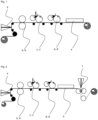
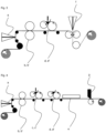
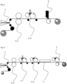
- a base film 1 is produced in a manner known per se (not shown), e.g. by Calendering.
- This base film 1 is printed in a known manner (unless it is a colored film for single-colored components) and if necessary provided with a primer 5 on the underside (bottom means facing the substrate) and/or irradiated.
- the base film 1 is usually rolled up and stored.
- the printed (or colored) base film 1 is unrolled and a reactive melt mass is applied to the base film 1 or the print D.
- an intermediate layer 2 without particles is first applied by means of a slot nozzle a.
- the intermediate layer 2 on the base film 1 is embossed with a pair of rollers b, b'.
- an abrasion-resistant polyurethane-based melt coating with particles is applied as a second or third layer 3 using rollers c, c'.
- the heated PUR melt coating 3 hardens after application through contact with the air humidity.
- radiation curing can be provided for radiation-curing reactive melt masses.
- the varnish 4 here a UV-curing acrylate varnish
- the varnish 4 is cured by UV radiation from the radiation source.
- the curing of the varnish is carried out, for example, by UV lamps, LED spotlights; an excimer laser or excimer UV spotlight is also used if necessary to achieve a matting and improved scratch resistance of the surface.
- a polymer protective layer 6 is poured onto the paint, according to Figure 4 raked and according to Figure 6 rolled up.
- the polymer protective layer 6 is poured directly onto the PUR melt coating 3, in Figure 5 (not according to the invention) and in Figure 7 (not according to the invention) rolled on.
- the finished UV protection film is wound up and is ready for coating substrates after the melt coating(s) have cured. It includes Figures 1, 2 , 4 , and 6 an intermediate layer and a varnish, as well as the Figures 2 to 7 a polymer protective layer. Figure 3 , 5 and 7 the lacquer and the intermediate layer are missing (not according to the invention), Figure 1 a polymer protective layer.
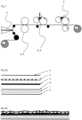
- FIGs 8a and 8b show schematically the layers of a first preferred UV protection film separated and brought together. Here you can see how the embossing of the intermediate layer 2 determines the surface structure of the UV protection film. PUR melt coating 3 and varnish 4 follow the structure of the intermediate layer 2.
- FIGs 9a and 9b show schematically the layers of a second preferred UV protection film separated and brought together. Here you can see how the embossing of the intermediate layer 2 determines the surface structure of the UV protection film. PUR melt coating 3, varnish 4 and polymer protection layer 6 follow the structure of the intermediate layer 2.
- FIGS. 10a and 10b show schematically the layers of a third preferred UV protection film separated and brought together. Here you can see how the embossing of the intermediate layer 2 determines the surface structure of the UV protection film. PUR melt coating 3 and polymer protection layer 6 follow the structure of the intermediate layer 2.
- the invention also relates to all combinations of preferred embodiments, provided that they do not exclude each other.
- the terms "about” or “approx.” in connection with a numerical specification mean that values that are at least 10% higher or lower or 5% higher or lower and in any case 1% higher or lower are included. Unless otherwise stated or apparent from the context Unless otherwise stated, percentages refer to the weight, in case of doubt to the total weight of the mixture.
Landscapes
- Life Sciences & Earth Sciences (AREA)
- Engineering & Computer Science (AREA)
- Wood Science & Technology (AREA)
- Laminated Bodies (AREA)
- Floor Finish (AREA)
- Paints Or Removers (AREA)
- Adhesives Or Adhesive Processes (AREA)
Description
- Die vorliegende Erfindung betrifft UV Schutzfolien für den Außenbereich, speziell zur Beschichtung von Bauelementen wie Bodenbelägen, insbesondere von Terassendielen, die zur Nutzung im Freien bestimmt sind.
- Ein wichtiger Trend in den letzten Jahren sind wertig aussehende Bauelemente für den Außenbereich. Immer mehr Menschen gestalten Terassen, Balkone und Sitzplätze im Freien als weiteren "Wohnraum". Dazu gehören neben entsprechendem Mobiliar auch wohnliche Bodenbeläge, Sichtschutzelemente, Zäune, Pflanzkästen und vieles mehr. Zwar ist die Optik von Naturstein und Holz weitgehend bevorzugt, aber es werden pflegeleichtere Oberflächen verlangt.
- Diese Anforderungen lassen sich durch Kunststoffe vereinbaren. Neben dem Einsatz von massivem Kunststoff, in jüngerer Zeit auch sog. WPC-Materialien (wood plastic composite), ist es seit langem bekannt, Substrate zu beschichten. Das ist auch bei Elementen wie Wänden oder Zäunen sehr erfolgreich. Bei Bodenbelägen ist jedoch bisher die Widerstandsfähigkeit nicht ausreichend und/oder es kommt zu anderen Mängeln. So haben die von Möbeln und Fußbodenpaneelen für den Innenbereich bekannten Laminierfolien im Außenbereich unter anderem das Problem, dass Dekorpapiere aufgrund mangelnder UV-Schutzwirkung der oberen Schicht(en) ausbleichen und die Oberfläche oft zu glatt ist, so dass die für Böden im Außenbereich erforderliche Rutschsicherheit nicht erreicht Somit besteht weiter die Aufgabe, pflegeleichte und dauerhafte Oberflächen mit gewünschter Optik für den Außenbereich bereitzustellen.
US 2018/162108 A1 offenbart eine UV Schutzfolie zur Herstellung von beschichteten Bauelementen für den Außenbereich durch Laminierung der Schutzfolie auf Bauelemente, wobei die Schutzfolie eine Basisfolie aus Polyvinylchlorid, Polyacrylat oder Polyethylen, ein gedrucktes Design, eine abriebbeständige Schmelzbeschichtung auf Polyurethanbasis umfassend UV Absorber und optional Füllstoffe, und einen Polyurethanlack umfasst. - Überraschend wurde nun gefunden, dass bedruckte Basisfolien aus PVC, Polyacrylat oder Polyolefin, die mit einer abriebbeständigen Schmelzbeschichtung auf Polyurethanbasis versehen und lackiert werden, einen wirksamen UV Schutz aufweisen und damit die notwendige Dauerhaftigkeit des Druckdesigns erreicht wird. Die Rutschsicherheit wird durch eine Prägung in Kombination mit der abriebbeständigen PUR-Schmelzbeschichtung gewährleistet. Die Prägung ist in einer bevorzugten Variante besonders einfach durch eine geprägte Zwischenschicht unterhalb der PUR-Schmelzbeschichtung erhältlich.
- Die obige Aufgabe wird somit durch eine UV Schutzfolie nach Anspruch 1 gelöst, die umfasst
- eine Basisfolie aus PVC, Polyacrylat oder Polyolefin,
- ein gedrucktes Design und/oder eine Einfärbung der Basisfolie,
- eine geprägte Zwischenschicht umfassend eine Reaktivschmelzmasse auf Polyurethanbasis
- eine abriebbeständige Schmelzbeschichtung auf Polyurethanbasis, und
- einen Lack und/oder eine Polymerschutzschicht.
- Außerdem wird die Aufgabe durch ein Verfahren zur Herstellung von beschichteten Bauelementen nach Anspruch 9 gelöst, bei dem diese UV Schutzfolie mit einem Substrat laminiert wird, durch die Verwendung der UV Schutzfolie zum Beschichten von Substraten und durch ein Verfahren zur Herstellung von UV Schutzfolien, bei dem eine Basisfolie aus PVC, Polyacrylat oder Polyolefin mit einem Design bedruckt wird und/oder eingefäbt ist, eine Schmelzbeschichtung auf Polyurethanbasis und darüber ein Lack und/oder eine Polymerschutzschicht aufgebracht wird, wobei eine Schicht unterhalb des Lacks geprägt wird.
- Die erfindungsgemäßen UV Schutzfolien haben einen mindestens vierschichtigen Aufbau. Weitere Schichten sind möglich, z.B. ein Primer auf der Unterseite der Basisfolie. Die Schichten der UV Schutzfolie können jeweils unabhängig voneinander aus mehreren Lagen bestehen. Beispielsweise können dicke Schichten durch mehrmaliges Aufrakeln des Materials erhalten werden oder eine Basisfolie durch Coextrusion hergestellt sein. Die Lagen können identisch oder unterschiedlich zusammengesetzt sein.
- Im Rahmen der vorliegenden Erfindung meint unten, unterhalb, Unterseite usw. diejenige Fläche einer Schicht, die dem Substrat zugewandt bzw. näher am Substrat ist. Oben, oberhalb und Oberseite bezeichnet eine vom Substrat abgewandte bzw. weiter entfernte Lage, die oberste Fläche der UV Schutzfolie bildet die Gebrauchsoberfläche des Bauelements.
- Als untere Schicht ist eine bedruckbare Basisfolie vorgesehen. Diese muss einerseits beim Laminieren mit dem Substrat eine ausreichende Haftung herstellen, andererseits verleiht sie der UV Schutzfolie als Träger während der Herstellung und Verarbeitung die notwendigen mechanischen Eigenschaften.
- Geeignete Materialien für die Basisfolie sind PVC (Polyvinylchlorid), Polyacrylate und Polyolefine. Diese weisen entweder als solches, zumindest aber mit an sich bekannten Additiven, eine gute UV-Stabilität auf. Zudem sind sie sehr gut gegen Hydrolyse und Thermolyse beständig.
- Die Verbindung mit dem Substrat erfolgt in der Regel über eine Kleberlaminierung, z.B. mittels Polyurethanhotmeltkleber. Zur Optimierung der Haftung kann die Basisfolie unterseitig mit einem Primer versehen werden. Beispielsweise ist ein Primer auf Basis von Vinylchlorid-Vinylacetat-Copolymer für PVC, Polyacrylat und PVC-Polyacrylat Folien gut geeignet. Für Polyolefinfolien eignet sich u.a. ein 2-Komponenten Polyurethanprimer. Die Basisfolie kann alternativ oder zusätzlich einer Plasmastrahlung oder Koronabehandlung oder anderen Oberflächenbehandlung unterzogen werden.
- Eine PVC-Basisfolie enthält vorzugsweise neben dem Polyvinylchlorid einen Stabilisator, Verarbeitungshilfsmittel, UV-Absorber, ein Antistatikum und Pigmente. Bevorzugt sind auch Modifier, insbesondere Polyacrylat, und epoxidiertes Sojabohnenöl enthalten. Als Stabilisator hat sich besonders Zinn bewährt, ebenso sind BaZn und CaZn brauchbar. Zinn wird vorzugsweise in Kombination mit Phosphit als Costabilisator verwendet. Bei den Verarbeitungshilfsmitteln handelt es sich beispielsweise um polymere Fließhilfen, z.B. auf Basis von MMA, BA, Styrol. Außerdem können PVC Folien mit Polymerweichmacher und mit Copolymer - insbesondere auf Basis von Vinylchlorid und Acrylaten - verwendet werden.
- Der PVC Anteil beträgt typischerweise 70 Gew.-% bis 85 Gew.-%. Der Weichmacheranteil liegt in der Regel bei bis zu 30 Gew.-%, kann aber durch geeignete Rohstoffergänzungen bzw. alternative Rohstoffe wie zum Beispiel Copolymere ganz oder teilweise ersetzt werden. Ein Baustein in der Rezeptur kann recyceltes Material sein. Die Menge kann auf bis zu 20 Gew.-% gesetzt werden, bevorzugt sind bis zu 5 Gew.-%. Das eingebrachte Material kann dabei von gleicher oder leicht abgeänderter Rezeptur sein.
- Polyacrylat-Basisfolien können vorzugsweise aus Methylmethacrylat (MMA), Butylacrylat (BA) und/oder Ethylacrylat (EA) sein, insbesondere werden Copolymere aus zwei, besonders bevorzugt aus allen drei der genannten Monomere eingesetzt. Die Basisfolie enthält außerdem üblicherweise ein oder mehrere von UV Absorbern z.B. auf Benzotriazolbasis, Antioxidationsmitteln wie beispielsweise phenolischen Antioxidationsmitteln, Lichtstabilisatoren, bevorzugt HALS, und Pigmenten. Außerdem können Verarbeitungshilfen auf Basis Polyacrylat enthalten sein.
- Polyolefin-Basisfolien können bevorzugt aus Polyethylen, Polypropylen oder Olefin-Copolymeren sein. Die Folien können Füllstoff enthalten, z.B. Kreide, und die üblichen Additive. Beispielsweise kann die Polyolefin-Basisfolie je 100 Gewichtsteile Polyolefin oder Polyolefinlegierung, vorzugsweise Propylenhomopolymerisat oder Polyethylen hoher Dichte (HDPE), 25 bis 120 Gewichtsteile eines feinteiligen mineralischen Füllstoffes oder mineralischen Füllstoffgemisches, vorzugsweise Calciumcarbonat, Erdalkalioxide, Mikrotalcum, Kaolin, Silicate, Magnesium-Aluminium-Oxy- oder -Hydroxy-Carbonate und/oder Silicate und/oder Kieselsäuregel mit einem mittleren Körnungsdurchmesser unter 10 µm, vorzugsweise von 0,05 bis 5 µm, enthalten. Nach einer anderen Ausführungsform enthält die Polyolefin-Basisfolie je 100 Gewichtsteile Polyolefin oder Polyolefinlegierung, vorzugsweise Propylenhomopolymerisat oder HDPE, 5 bis 40 Gewichtsteile (bezogen auf 100 Gewichtsteile Polyolefin), vorzugsweise 10 bis 30 Gewichtsteile, mindestens eines feinteiligen organischen Füllstoffes oder Kombinationen dieser Gewichtsmengen organischer Füllstoffe mit 0 bis 30 Gewichtsteilen, vorzugsweise 5 bis 25 Gewichtsteilen, mindestens eines feinteiligen mineralischen anorganischen Füllstoffes oder Füllstoffgemisches.
- Die Stärke der Basisfolie beträgt normalerweise von 80 bis 250 µm, vorzugsweise von 100 bis 200 µm und besonders bevorzugt von 120 bis 160 µm. Die Basisfolie wird in der Regel durch Kalandrieren hergestellt, kann aber auch extrudiert sein. Extrudieren schließt alle Verfahren, nämlich Blasfolien-, Gießfolien- und Castfolien-Extrusion, mit ein. Bevorzugt ist die Gießfolienextrusion. Die Schmelze wird über eine Breitschlitzdüse verteilt und durch eine Kühlwalze/Chillwalze abgekühlt. Als Werkzeuge sind Einschnecken- und Mehrschneckenextruder und deren Variationen denkbar. Bevorzugt erfolgt die Herstellung mit einem Einschneckenextruder. Die Basisfolie kann uni- oder bi-direktional verstreckt werden. Dadurch erhält sie eine höhere Dimensionsstabilität gegenüber den Temperaturen während des Auftrags der Schmelzbeschichtung. Zudem wird das Risiko von Mikrorissen in der Schmelzbeschichtung bei einem Ummanteln von Substraten mit der erfindungsgemäßen UV-Schutzfolie minimiert. Durch ein Verstrecken passt sich die Dehnbarkeit der Basisfolie derjenigen der Schmelzbeschichtung an, d.h. sie wird ähnlich gering.
- Auf der Basisfolie wird das gewünschte Design aufgedruckt, sofern nicht für Unifarben die Basisfolie eingefärbt ist. Die Basisfolie kann hierbei durchgefärbt sein bzw. bei mehrlagigen Basisfolien kann die oberste Lage durchgefärbt sein. Dies ist für unifarbene Designs bevorzugt. Auch für eine Bedruckung kann durch eine durchgefärbte Basisfolie oder oberste Lage der Basisfolie eine Grundfarbe bereitgestellt werden. Der Designdruck kann auf jede bekannte Art erzielt werden. Besonders brauchbar sind z.B. Tiefdruck, insbesondere mit Lösungsmittelfarben, und Digitaldruck. Als Design sind Holzdekor, Naturstein und Phantasiemuster ebenso möglich, wie Unifarben. Die Druckfarbe wird z.B. durch eine Reihenschaltung an Druckwalzen auf die Basisfolie appliziert. Im Digitaldruck können sowohl Single-Pass als auch Multi-Pass Druckköpfe zur Gestaltung verwendet werden. Die Druckbilder werden oftmals aus mehreren Druckfarben zusammengesetzt und zeichnen sich durch Lichtstabilität aus. Neben lösungsmittelbasierten Druckfarben sind auch solche mit wässriger Basis denkbar.
- Die eingesetzten Pigmente zur Durchfärbung der Basisfolie oder deren oberster Lage und zur Erzeugung von Unifarben können organisch und anorganisch sein und den IR-Anteil im Sonnenlicht reflektieren oder transmittieren.
- Oberhalb des Drucks werden eine geprägte Zwischenschicht und eine abriebbeständige Schmelzbeschichtung auf Polyurethanbasis aufgebracht. Mit Schmelzbeschichtung auf Polyurethanbasis, auch kurz PUR-Schmelzbeschichtung oder Schmelzbeschichtung genannt, ist im Rahmen der vorliegenden Erfindung eine Reaktivschmelzmasse gemeint, wie sie z.B. in
WO 2006/056472 A1 ,WO 2012/084823 A1 ,WO 2006/106143 A1 oderUS 8,153,265 B2 beschrieben ist. Die Reaktivschmelzmasse kann z.B. durch die Feuchtigkeit der Umgebung reagieren und aushärten, aber auch durch Bestrahlung mit z.B. UV-Licht. Es kann eine ein- oder zweikomponentige Masse sein. Wichtig ist, dass es sich um eine transparente PUR-Schmelzbeschichtung handelt, damit die Farbe bzw. der Druck durch die Schmelzbeschichtung sichtbar bleibt. - Vorzugsweise werden durch die Luftfeuchtigkeit aushärtende ein-komponentige Reaktivschmelzmassen eingesetzt, die ein Polyurethanprepolymer enthalten. Beim Erhitzen verflüssigen sich die Prepolymerketten zu einer applizierbaren Flüssigkeit, die unter Zufuhr von Feuchte zu einer Polyurethanschicht aushärtet.
- Zur Steigerung der Abriebfestigkeit enthält die Reaktivschmelzmasse der abriebbeständigen Schmelzbeschichtung Partikel mit entsprechender Härte. Bevorzugt sind als Schleifmittel verwendete Partikel wie Korund, Zirkon, Siliciumcarbid, Bornitrid, Diamant oder Glaspartikel. Insbesondere Korund und Glaspartikel sind aufgrund der Wirtschaftlichkeit bevorzugt.
- Die abriebbeständige PUR-Schmelzbeschichtungs-Schicht hat normalerweise eine Stärke von 10 bis 150 µm, vorzugsweise von 20 bis 120 µm und insbesondere von 30 bis 100 µm. Sie kann in an sich bekannter Weise durch Aufstreichen, Aufrakeln, Walzenauftrag etc. aufgebracht werden.
- Unter der abriebbeständigen PUR-Schmelzbeschichtung ist eine geprägte Zwischenschicht angeordnet, die ebenfalls aus einer Reaktivschmelzmasse auf Polyurethanbasis gebildet wird, jedoch keinen oder wesentlich weniger Füllstoff als die abriebbeständige PUR-Schmelzbeschichtung enthält. Auch die Zwischenschicht muss transparent sein. Durch die Zwischenschicht ist es besonders einfach möglich, die gesamte PUR-Schmelzbeschichtung blasenfei und damit hochtransparent zu erhalten. Ohne eine füllstofffreie Zwischenschicht können beim Applizieren der PUR-Schmelzbeschichtung Gasbläschen eingetragen werden, welche die Transparenz beeinträchtigen.
- Die Stärke der Zwischenschicht richtet sich nach der gewünschten Prägetiefe und der Stärke der PUR-Schmelzbeschichtungs-Schicht und beträgt in der Regel von 10 bis 100 µm, vorzugsweise von 20 bis 80 µm, besonders bevorzugt 30 bis 60 µm.
- Der Auftrag der Zwischenschicht kann in gleicher Weise wie der Auftrag der PUR-Schmelzbeschichtung erfolgen, wobei für die Beschichtungen einer Folie gleiche oder unterschiedliche Verfahren benutzt werden können. In einer bevorzugten Ausführungsform wird die Zwischenschicht mittels einer Schlitzdüse, mit oder ohne Rollstab, aufgebracht, und die PUR Schmelzbeschichtungs-Schicht mittels Walzenauftrag. Zweckmäßig wird für die Zwischenschicht die gleiche Reaktivschmelzmasse wie für die abriebbeständige PUR-Schmelzbeschichtung aber ohne Partikel verwendet. Es ist auch möglich, eine andere Reaktivschmelzmasse zu verwenden, z.B. eine strahlenhärtbare Masse für die Zwischenschicht und eine durch Feuchtigkeit aushärtende Masse für die Schmelzbeschichtung. Die Zwischenschicht kann auch als Folie bereitgestellt werden, z.B. als geprägte Folie. Die Zwischenschicht verbessert den UV-Schutz wesentlich, da keine oder wenig Partikel enthalten sind. Ohne die Zwischenschicht könnten Partikel in der PUR-Schmelzbeschichtung bis zur Basisfolie reichen und damit Licht direkt auf das gedruckte Design durchlassen.
- Die Prägung der Zwischenschicht erfolgt in an sich bekannter Weise, z.B. mit einem Walzenpaar. Wie ebenfalls bekannt kann das Prägemuster auf das Druckdesign abgestimmt sein und mit diesem korrespondieren. So ist es üblich, dass eine Prägung der Maserung der gedruckten Holzstruktur folgt oder bei einer Fliesenoptik Fugen simuliert.
- Typische Prägetiefen betragen von 5 bis 30 µm, vorzugsweise von 10 bis 20 µm. Dies gewährleistet in Kombination mit den Partikeln in der PUR-Schmelzbeschichtungs-Schicht eine ausreichende Rutschhemmung. Üblicherweise werden Rutschsicherheitswerte von mindestens R10 bis R12 nach DIN 51130 bzw. ASR A1.5/1,2 erreicht, vorzugsweise von mindestens R11.
- Die obere Schicht wird von einem transparentem Lack und/oder einer abziehbaren Polymerschutzschicht gebildet. Die Folie ist aufgrund der PUR Schmelzbeschichtungsschicht auf der Oberfläche sehr rau. Das ist auch gewünscht um eine hohe Rutschhemmung im nassen Zustand zu erreichen. Eine sehr raue und sehr harte abriebbeständige Oberfläche hat aber den Nachteil, dass sich die Andruckwalzen von Ummantelungs- oder Beschichtungsanlagen in kürzester Zeit abnutzen und der Prozess instabil wird. Reklamationen durch fehlerhafte Beschichtung sind die Folge. Daher wird die Oberfläche der erfindungsgemäßen Schutzfolie von dem Lack oder der Polymerschutzschicht gebildet. Das Aufbringen eines Lackes oder einer Polymerschutzschicht ist auch nötig um die Folie mit der PUR Schmelzmassenbeschichtung sofort aufwickeln zu können. Ansonsten verblockt die Folienrolle, da es normalerweise einige Zeit dauert, bis die aufgetragene(n) Schmelzbeschichtung(en) blockfest ausgehärtet ist(sind). Wenn die Polymerschutzschicht keine zu große Haftung zur PUR-Schmelzmasse aufbaut, kann man die Lackschicht weglassen, das Material ist durch die Schutzschicht aufwickelbar. Ein zusätzlicher Vorteil der Schutzschicht ist ein Schutz der Oberfläche des Bauelementes gegen Verkratzen z.B. durch die rutschhemmende PUR-Schmelzbeschichtung anderer Bauteile. Ein Lack bleibt Teil der erfindungsgemäßen Schutzfolie, die Polymerschutzschicht wird nach Fertigung des Bauelements oder direkt vor bzw. nach seiner Verlegung/Installation abgezogen.
- Als Lack sind Acrylatlacke und Polyurethanlacke bevorzugt, insbesondere strahlenhärtbare Lacke. Die Vernetzung des Lacks erfolgt vorzugsweise durch UV- oder LED Strahler. Dies kann durch eine einzelne oder mehrere Quellen geschehen. Die Energieleistung beträgt dabei z.B. 30 W bis 200 W, bevorzugt 50 W bis 180 W, insbesondere 90 W bis 150 Watt.
- Der Lack wird zweckmäßig mittels Walzenapplikation oder durch Sprühauftrag appliziert und ggfs. durch Bestrahlung gehärtet. Stärken von 1 bis 50 µm, vorzugsweise von 3 bis 15 µm, besonders bevorzugt von 5 bis 10 µm, haben sich bewährt. Der Lack verbessert zum einen den UV-Schutz, zum anderen stellt er eine Antiblockwirkung bereit, so dass sich die UV Schutzfolie aufwickeln und vor allem problemlos abwickeln lässt. Der Lack hat normalerweise einen niedrigen Glanzgrad von 4 bis 20 Glanzpunkten, vorzugsweise bis 15 Glanzpunkten, gemäß ISO 2813. Die Messung erfolgt mittels eines Goniophometers. Der Messwinkel kann 20°, 35°, 60° (bevorzugt) und 80° oder 85° betragen.
- Als Polymerschutzschicht kommt bevorzugt eine Schmelzmasse aus Polyethylen (PE, bevorzugt HDPE) oder aus PE (bevorzugt LDPE im Gemisch mit linearem Polyethylen niederer Dichte, LLDPE) und Ethylenvinylacetat (EVA) zum Einsatz. EVA hat typischerweise einen Vinylacetatgehalt im Bereich von 15 bis 25 Gew.-%.
- Die Polymerschutzschicht kann Additive wie Thermostabilisatoren, HALS, UV-Stabilisatoren und ggfs. Füllstoffe enthalten. In einer bevorzugten Ausführungsform sind keine Additive enthalten oder nur UV-Stabilisatoren in geringerer als der üblichen Menge.
- Das Material der Polymerschutzschicht zeigt durch Wahl des richtigen Gewichtsverhältnisses von PE zu EVA eine gewünschte Haftung zu der PUR-Schmelzmassenschicht oder dem Lack. Die Haftung soll ausreichen, dass die Polymerschutzschicht sich bis zum Abschluss der Bauelementfertigung nicht wesentlich ablöst. Sie muss gering genug sein, um ein Abziehen der Schutzschicht zu erlauben. Die Mischungsverhältnisse hängen von der eingestellten Oberflächenrauigkeit sowie ggfs. auch von der gewünschten Haftung zum Lack ab. Das Mischungsverhältnis PE:EVA, bezogen auf die Masse, kann je nach gewünschter Haftung von 1:5 bis 5:1, vorzugsweise von 1:1 bis 3:1, betragen. Die Haftung kann auch durch Mischung verschiedener PE beeinflusst werden, so führt eine Zumischung von LLDPE zu einer verstärkten Haftung und gleichzeitig verbesserten Reißfestigkeit, was das Abziehen erleichtert. Auch andere Schmelzmassen, die mit der PUR-Schmelzbeschichtungsschicht oder dem Lack die gewünschte Haftung aufbauen, sind möglich, z.B. Massen die als Schutz für PVCkaschierte Bleche bekannt sind.
- Die Polymerschutzschicht kann nach der PUR Schmelzmassenbeschichtung oder nach dem Lackieren auf die raue Oberfläche im Gießbeschichtungsverfahren, Rakelverfahren oder Walzverfahren aufgetragen werden. Bevorzugt ist das Gießverfahren in einen gekühlten Walzenspalt. In diesem Prozess läuft die Schmelzmasse in die Täler und entschärft die abrasive Wirkung. Die den Ummantelungsandruckrollen zugewandte Seite ist vornehmend glatt ausgebildet.
- Die Auftragsmenge hängt von der Struktur der rutschhemmenden PUR-Schmelzbeschichtung ab und beträgt von 20 g/m2 bis 200 g/m2, bevorzugt von 100 g/m2 und 150 g/m2.
- Die Gesamtstärke der UV Schutzfolie ohne Polymerschutzschicht beträgt üblicherweise von 10 bis 150 µm, vorzugsweise von 40 bis 100 µm und besonders bevorzugt von 50 bis 80 µm.
- Die erfindungsgemäße UV-Schutzfolie hat vorzugsweise mindestens eine der folgenden Eigenschaften:
- Kratzfestigkeit ≥ 3 N, vorzugsweise ≥ 4 N, nach DIN 15186, bzw. mindestens Klasse A3 nach DIN EN 16094:2012-04 und B3 nach DIN CEN/TS 16611:2014, und/oder
- Abrieb- und Verschleißfestigkeit ≥ 3.000 Umdrehungen, vorzugsweise ≥ 4.000 Umdrehungen nach DIN EN 13329 bzw. ≥ 8.000 Umdrehungen, vorzugsweise 10.000 Umdrehungen nach EN 14354:2017-11, und/oder
- Witterungsbeständigkeit mit mindestens 10.000, vorzugsweise mindestens 15.000, Teststunden nach EN 513 (Verfahren 1 (M)) und dabei eine Mindeststabilität der Farbe von Graumaßstab 3, bewertet nach EN 20105-A02 und/oder
- Rutschfestigkeit erreicht mindestens Klasse R10, was nach DIN 51130:2014 einer Mindestschräge von 10° entspricht, vorzugsweise R11.
- Als Substrate kommen Holz, Metall, Kunststoff und Verbundwerkstoffe in Betracht. Das Substrat stellt die notwendigen mechanischen Eigenschaften für das Bauelement bereit. Durch die Beschichtung mit der UV Schutzfolie erfolgt einerseits die gewünschte optische Gestaltung, andererseits wird damit das Substrat auch vor der Witterung geschützt. Kunststoffe altern nicht durch UV-Licht, Metalle korrodieren nicht, Holz bleibt trocken und wird ebenfalls vor UV-Licht geschützt. Die Oberfläche ist leicht zu reinigen und bleibt so wesentlich länger und mit viel weniger Aufwand optisch ansprechend.
- Typische Bauelemente sind Bodendielen und -platten für Terassen, Balkone, Wege etc., Paneele, Zaunpfähle und -elemente, Sichtschutzelemente, und Pflanzkästen. Von besonderem Interesse sind gemäß der Erfindung die Bodenbeläge, da diese hohe Anforderungen an die Rutschsicherheit stellen, besonders schnell verschmutzen und eine hohe UV- und mechanische Belastung haben. Bisherige Produkte haben oft die Rutschsicherheit nicht erreicht, wurden durch UV-Licht zu schnell in der Optik verschlechtert und/oder waren den mechanischen Belastungen nicht gewachsen. Delaminierung, besonders an Ecken und Kanten, kam häufig vor.
- Die erfindungsgemäß hergestellten Bauelemente haben demgegenüber einen verbesserten UV-Schutz, insbesondere bei Vorliegen der Zwischenschicht, und müssen keine Kompromisse in Sachen Rutschsicherheit machen. Auch die mechanische Belastbarkeit ist verbessert, da die Haftung der Basisfolie auf dem Substrat und der Folienschichten untereinander durch die beschriebenen Maßnahmen optimal ist.
- Bekannt für den Einsatz im Außenbereich sind z.B. die Elesgo Folie auf Papierbasis. Bei dieser Folie wird eine mit Acrylat imprägnierte bedruckte Papierfolie mit einem dicken korundhaltigen Acryllack beschichtet. Die oberste Struktur wird durch eine Strukturgeberfolie erzeugt, wobei lediglich Rutschhemmungen im Bereich von R10 zu erreichen sind. Dies ist für ein sicheres Begehen bei Nässe ein geringer Wert. Varianten dieser Folie auf Kunststoffbasis mit einer verbesserten inneren Festigkeit haben aufgrund der identischen Herstellungstechnologie der Beschichtung das gleiche negative Rutschverhalten. Der Prozess ist unter https://laminate.de/index.php/de/technologie2/prozess gezeigt.
- Weiterhin sind HPL Compactplatten bekannt, die auf der Basis von Melamin oder Phenolharzgetränkten Papieren erzeugt werden. Viele dieser Produkte haben aufgrund des Druckes eine geringe Lichtbeständigkeit. Die Rutschhemmung dieser Produkte wird über Pressbleche erzeugt, was die Wirksamkeit von eingestreutem Korund in die oberste Papierlage verringert. So wird zwar eine gute Abbriebbeständigkeit erreicht, die Rutschhemmung ist aber eher gering, da die Pressbleche aufgrund des Prozesses sonst schnell verschlissen sind.
- Der aktuelle Stand der Technik kennt im horizontalen Außenbereich keine hochwertigen Dekore, wie sie mit dieser Erfindung umgesetzt werden können. Bestehende Systeme scheitern bereits nach wenigen Jahren an dem hohen Anspruch. Bekannte Fehler sind ein Trennen der Schichten, Brechen der Schichten, Ausbleichen und Verändern der Farbe aufgrund der Verwendung ungeeigneter UV-Schutzschichten, schwierige Prozessführung aufgrund zu hoher Steifigkeiten, Begünstigung einer Wasseraufnahme und daraus resultierendes Quellvermögen, mangelnde Haftung zum Trägermaterial.
- Weiterhin sind die erfindungsgemäßen UV-Schutzfolien sehr gut zur dekorativen Gestaltung von Schwimmbadabdeckungen geeignet (sog. Rollladensystem). Bisher bekannte Kunststofffolien sind häufig an der fehlenden Witterungsstabilität gescheitert. Bei Kunststofffolien mit einer transparenten Polyacrylatschicht als Witterungsschutz ist deren Eintrübung durch Wasseraufnahme ein Problem. Bei den erfindungsgemäßen UV-Schutzfolien sind dagegen eine gute Stabilität in chlorhaltigem (und auch salzhaltigem) Schwimmbadwasser sowie die notwendige Witterungsstabilität gegeben. Als Substrat sind die bekannten Rolladen-ähnlichen Abdeckungen geeignet mit der Bedingung, dass die Abdeckung schwimmfähig sein muss. Somit sind Segmente aus Holz, Kunststoff und Verbundwerkstoffen bevorzugt, bei den besonders bevorzugten hohlen Segmenten solche aus Kunststoff, Verbundwerkstoffen und Metall.
- Ausführungsformen des erfindungsgemäßen Verfahrens zur Herstellung der UV Schutzfolie sind in
Figuren 1, 2 ,4 , und6 veranschaulicht. Die inFigur 3 ,5 und7 illustrierten Verfahren liegen nicht im beanspruchten Umfang der Erfindung. Für gleiche Verfahrensabläufe werden gleiche Bezugszeichen für die in den Figuren gezeigten Vorrichtungen verwendet. Bei allen veranschaulichten Verfahren wird eine Basisfolie 1 in an sich bekannter Weise hergestellt (nicht gezeigt), z.B. durch Kalandrieren. Diese Basisfolie 1 wird in ebenso bekannter Weise bedruckt (sofern es sich nicht um eine eingefärbte Folie für einfarbige Bauelemente handelt) und ggfs. unterseitig (unten meint dem Substrat zugewandt) mit einem Primer 5 versehen und/oder bestrahlt. Üblicherweise wird die Basisfolie 1 aufgerollt und eingelagert. Im nächsten Schritt wird die bedruckte (oder eingefärbte) Basisfolie 1 abgerollt und eine Reaktivschmelzmasse auf die Basisfolie 1 oder den Druck D aufgebracht. - In den in
Figuren 1, 2 ,4 und6 gezeigten Ausführungsformen wird zunächst eine Zwischenschicht 2 ohne Partikel mittels Schlitzdüse a appliziert. Die Zwischenschicht 2 auf der Basisfolie 1 wird mit einem Walzenpaar b, b' geprägt. - In allen Figuren wird eine abriebbeständige Schmelzbeschichtung auf Polyurethanbasis mit Partikeln als zweite bzw. dritte Schicht 3 mittels Walzen c, c' appliziert. Die erwärmte PUR-Schmelzbeschichtung 3 härtet nach dem Auftrag durch Kontakt mit der Luftfeuchtigkeit aus. Alternativ kann für strahlenhärtende Reaktivschmelzmassen eine Strahlenhärtung vorgesehen sein.
- Dann wird in
Figuren 1, 2 ,4 und6 der Lack 4, hier ein UV-härtender Acrylatlack, mittels Walzenauftrag durch die Walzen d, d' aufgetragen. Der Lack 4 wird durch UV-Strahlung aus der Strahlungsquelle gehärtet. Die Aushärtung des Lacks erfolgt z.B. durch UV-Lampen, LED-Strahler; ein Excimerlaser oder Excimer-UV-Strahler wird ggf. zusätzlich genutzt, um eine Mattierung und verbesserte Kratzfestigkeit der Oberfläche zu erreichen. - Gemäß
Figur 2 wird auf den Lack eine Polymerschutzschicht 6 aufgegossen, gemäßFigur 4 aufgerakelt und gemäßFigur 6 aufgewalzt. InFigur 3 (nicht gemäß der Erfindung) wird die Polymerschutzschicht 6 direkt auf die PUR Schmelzbeschichtung 3 aufgegossen, inFigur 5 (nicht gemäß der Erfindung) aufgerakelt und inFigur 7 (nicht gemäß der Erfindung) aufgewalzt. - Die fertige UV Schutzfolie wird aufgewickelt und ist nach dem Aushärten der Schmelzbeschichtung(en) zum Beschichten von Substraten bereit. Sie umfasst bei den
Figuren 1, 2 ,4 , und6 eine Zwischenschicht und einen Lack, sowie bei denFiguren 2 bis 7 eine Polymerschutzschicht. BeiFigur 3 ,5 und7 fehlen der Lack und die Zwischenschicht (nicht gemäß der Erfindung), beiFigur 1 eine Polymerschutzschciht. - Die
Figuren 8a und 8b zeigen schematisch die Schichten einer ersten bevorzugten UV Schutzfolie getrennt und zusammengebracht. Man erkennt hier, wie die Prägung der Zwischenschicht 2 die Oberflächenstruktur der UV Schutzfolie bestimmt. PUR-Schmelzbeschichtung 3 und Lack 4 folgen der Struktur der Zwischenschicht 2. - Die
Figuren 9a und 9b zeigen schematisch die Schichten einer zweiten bevorzugten UV Schutzfolie getrennt und zusammengebracht. Man erkennt hier, wie die Prägung der Zwischenschicht 2 die Oberflächenstruktur der UV Schutzfolie bestimmt. PUR-Schmelzbeschichtung 3, Lack 4 und Polymerschutzschicht 6 folgen der Struktur der Zwischenschicht 2. - Die
Figuren 10a und 10b zeigen schematisch die Schichten einer dritten bevorzugten UV Schutzfolie getrennt und zusammengebracht. Man erkennt hier, wie die Prägung der Zwischenschicht 2 die Oberflächenstruktur der UV Schutzfolie bestimmt. PUR-Schmelzbeschichtung 3 und Polymerschutzschicht 6 folgen der Struktur der Zwischenschicht 2. - Die Erfindung bezieht sich auch auf sämtliche Kombinationen von bevorzugten Ausgestaltungen, soweit diese sich nicht gegenseitig ausschließen. Die Angaben "etwa" oder "ca." in Verbindung mit einer Zahlenangabe bedeuten, dass zumindest um 10 % höhere oder niedrigere Werte oder um 5 % höhere oder niedrigere Werte und in jedem Fall um 1 % höhere oder niedrigere Werte eingeschlossen sind. Soweit nichts anderes angegeben ist oder sich aus dem Zusammenhang zwingend anders ergibt, beziehen sich Prozentangaben auf das Gewicht, im Zweifel auf das Gesamtgewicht der Mischung.
-
- 1
- Basisfolie
- 2
- Zwischenschicht
- 3
- PUR-Schmelzbeschichtung auf Polyurethanbasis
- 4
- Lack
- 5
- Primer
- 6
- Polymerschutzschicht
- D
- Druck
- a
- Schlitzdüse mit oder ohne Rollstab
- b, b'
- Prägewalzenpaar
- c, c'
- Walzenauftrag PUR-Schmelzbeschichtung
- d, d'
- Walzenauftrag Lack
- e
- Strahlungsquelle
- f
- Aufgießen (Direktextrusion) Polymerschutzschicht
- g
- Rakelauftrag Polymerschutzschicht
- h
- Walzenauftrag Polymerschutzschicht
Claims (18)
- UV Schutzfolie umfassend:- eine Basisfolie aus Polyvinylchlorid, Polyacrylat oder Polyolefin,- ein gedrucktes Design und/oder eine Färbung der Basisfolie,- eine abriebbeständige, transparente Schmelzbeschichtung auf Polyurethanbasis, die Partikel entsprechender Härte enthält, und- einen Lack und/oder eine Polymerschutzschicht, dadurch gekennzeichnet, dass unter der abriebbeständigen Schmelzbeschichtung auf Polyurethanbasis eine geprägte, transparente Zwischenschicht umfassend eine Reaktivschmelzmasse angeordnet ist, die keine oder weniger Partikel enthält als die abbriebbeständige Schmelzbeschichtung auf Polyurethanbasis.
- UV Schutzfolie gemäß Anspruch 1, dadurch gekennzeichnet, dass die Stärke der Zwischenschicht von 10 bis 100 µm, vorzugsweise von 20 bis 80 µm, besonders bevorzugt 30 bis 60 µm, beträgt.
- UV Schutzfolie gemäß Anspruch 1 oder 2, dadurch gekennzeichnet, dass die Basisfolie unterseitig einen Primer aufweist und/oder einer Plasmastrahlung oder Koronabehandlung unterzogen wurde.
- UV Schutzfolie gemäß einem der Ansprüche 1 bis 3, dadurch gekennzeichnet, dass die Basisfolie eine Stärke von 40 bis 250 µm, vorzugsweise von 100 bis 200 µm und besonders bevorzugt von 120 bis 160 µm hat.
- UV Schutzfolie gemäß einem der Ansprüche 1 bis 4, dadurch gekennzeichnet, dass die Partikel ausgewählt sind unter anderem aus Glaspartikeln, als Schleifmittel verwendeten Partikeln und Mischungen davon, vorzugsweise Korund.
- UV Schutzfolie gemäß einem der Ansprüche 1 bis 5, dadurch gekennzeichnet, dass die abriebbeständige Schmelzbeschichtung eine Stärke von 10 bis 150 µm, vorzugsweise von 20 bis 120 µm und insbesondere von 30 bis 100 µm hat.
- UV Schutzfolie gemäß einem der Ansprüche 1 bis 6, dadurch gekennzeichnet, dass der Lack ein Acrylatlack oder ein Polyurethanlack ist, vorzugsweise ein strahlenhärtbarer Acrylat- oder Polyurethanlack.
- UV Schutzfolie gemäß einem der Ansprüche 1 bis 7, dadurch gekennzeichnet, dass der Lack eine Stärke von 1 bis 50 µm, vorzugsweise von 3 bis 15 µm, besonders bevorzugt von 5 bis 10 µm, hat.
- Verfahren zur Herstellung von beschichteten Bauelementen, dadurch gekennzeichnet, dass eine UV Schutzfolie gemäß einem der Ansprüche 1 bis 8 mit einem Substrat laminiert wird.
- Verfahren gemäß Anspruch 9, dadurch gekennzeichnet, dass die UV Schutzfolie mit dem Substrat durch eine Hitzelaminierung oder eine Kleberlaminierung, z.B. mittels Polyurethanhotmeltkleber, laminiert wird.
- Verfahren gemäß Anspruch 9 oder 10, dadurch gekennzeicnet, dass das Substrat aus Holz, Metall, Kunststoff oder Verbundwerkstoff ist.
- Verfahren gemäß Anspruch 11, dadurch gekennzeichnet, dass das Bauelement ausgewählt ist unter Bodendielen und -platten, Paneelen, Zaunpfählen und -elementen, Sichtschutzelementen, Schwimmbadabdeckungen und Pflanzkästen.
- Verfahren zur Herstellung von UV Schutzfolien gemäß einem der Ansprüche 1 bis 8, umfassend- Herstellen einer Basisfolie aus PVC, Polyacrylat oder Polyolefin und Bedrucken der Basisfolie mit einem Design oder Herstellen einer eingefärbten Basisfolie aus PVC, Polyacrylat oder Polyolefin- Aufbringen einer Schmelzbeschichtung auf Polyurethanbasis auf die Basisfolie oder den Druck- Aufbringen eines Lacks und/oder einer Polymerschutzschicht wobei die Basisfolie und/oder eine Zwischenschicht unter der Schmelzbeschichtung und/oder die Schmelzbeschichtung geprägt wird, dadurch gekennzeichnet, dass eine geprägte Zwischenschicht auf Polyurethanbasis, die keinen oder wesentlich weniger Füllstoff als die Schmelzbeschichtung enthält, unter der Schmelzbeschichtung eingebracht ist.
- Verfahren gemäß Anspruch 13, dadurch gekennzeichnet, dass die Basisfolie im Tiefdruck, insbesondere mit Lösungsmittelfarben, oder im Digitaldruck bedruckt wird.
- Verfahren gemäß Anspruch 13 oder 14, dadurch gekennzeichnet, dass die abriebbeständige Schmelzbeschichtung durch Aufstreichen, Aufrakeln oder Walzenauftrag appliziert wird.
- Verfahren gemäß einem der Ansprüche 13 bis 15, dadurch gekennzeichnet, dass die geprägte Zwischenschicht auf Polyurethanbasis mit einer Schlitzdüse mit oder ohne Rollstab eingebracht ist.
- Verfahren gemäß einem der Ansprüche 13 bis 16, dadurch gekennzeichnet, dass die Prägetiefen von 5 bis 30 µm, vorzugsweise von 10 bis 20 µm, betragen.
- Verfahren gemäß einem der Ansprüche 13 bis 17, dadurch gekennzeichnet, dass der Lack durch Strahlung gehärtet wird und/oder die Polymerschutzschicht durch Aufgießen, Aufrakeln oder Walzenauftrag aufgebracht wird.
Applications Claiming Priority (3)
| Application Number | Priority Date | Filing Date | Title |
|---|---|---|---|
| DE102020126708 | 2020-10-12 | ||
| DE102020131858.8A DE102020131858B4 (de) | 2020-10-12 | 2020-12-01 | UV Schutzfolie für den Außenbereich, Verfahren zu ihrer Herstellung, Verwendung der Folie zum Beschichten und Verfahren zur Herstellung von Bauelementen |
| PCT/EP2021/078028 WO2022078946A1 (de) | 2020-10-12 | 2021-10-11 | UV SCHUTZFOLIE FÜR DEN AUßENBEREICH |
Publications (3)
| Publication Number | Publication Date |
|---|---|
| EP4225573A1 EP4225573A1 (de) | 2023-08-16 |
| EP4225573B1 true EP4225573B1 (de) | 2024-07-31 |
| EP4225573B8 EP4225573B8 (de) | 2024-09-11 |
Family
ID=80818144
Family Applications (1)
| Application Number | Title | Priority Date | Filing Date |
|---|---|---|---|
| EP21798295.8A Active EP4225573B8 (de) | 2020-10-12 | 2021-10-11 | Uv schutzfolie für den aussenbereich |
Country Status (10)
| Country | Link |
|---|---|
| EP (1) | EP4225573B8 (de) |
| JP (1) | JP2023549307A (de) |
| CA (1) | CA3194110A1 (de) |
| DE (1) | DE102020131858B4 (de) |
| DK (1) | DK4225573T3 (de) |
| ES (1) | ES2991771T3 (de) |
| FI (1) | FI4225573T3 (de) |
| PL (1) | PL4225573T3 (de) |
| PT (1) | PT4225573T (de) |
| WO (1) | WO2022078946A1 (de) |
Families Citing this family (1)
| Publication number | Priority date | Publication date | Assignee | Title |
|---|---|---|---|---|
| DE102023102824A1 (de) | 2023-02-06 | 2024-08-08 | Renolit Se | Mehrschichtiges Profilteil |
Citations (7)
| Publication number | Priority date | Publication date | Assignee | Title |
|---|---|---|---|---|
| WO2012084823A1 (de) * | 2010-12-20 | 2012-06-28 | Klebchemie M. G. Becker Gmbh & Co. Kg | Reaktive polyurethanzusammensetzung mit abriebfesten füllstoffen |
| WO2016010472A1 (en) * | 2014-07-16 | 2016-01-21 | Välinge Innovation AB | Method to produce a thermoplastic wear resistant foil |
| WO2016030215A1 (de) * | 2014-08-25 | 2016-03-03 | Profol Kunststoffe Gmbh | Geprägte und schmelzekaschierte mehrschichtverbundfolie |
| CN205774262U (zh) * | 2016-04-12 | 2016-12-07 | 上海协承昌化工有限公司 | 一种耐磨贴膜 |
| US20180162108A1 (en) * | 2016-12-12 | 2018-06-14 | Trex Company, Inc. | Laminated wood polymer composite article and method of making a laminated wood polymer composite article |
| DE102018005880A1 (de) * | 2018-07-26 | 2020-01-30 | Interprint Gmbh | Verwendung eines mehrlagigen Schichtaufbaus |
| EP3288688B1 (de) * | 2015-04-30 | 2021-06-09 | Klebchemie M.G. Becker GmbH & Co. KG | Verfahren zur herstellung von strukturierten oberflächen und derart strukturierte gegenstände |
Family Cites Families (7)
| Publication number | Priority date | Publication date | Assignee | Title |
|---|---|---|---|---|
| JPH0232030B2 (ja) * | 1981-05-22 | 1990-07-18 | Noda Plywood Mfg Co Ltd | Hotsutomerutotoryoomochiitakeshobanoyobisonoseizohoho |
| JP2001150660A (ja) * | 1999-12-01 | 2001-06-05 | Olympus Optical Co Ltd | インクジェットプリント済みエンボス加工内装素材及びその作成方法 |
| DE102004057292A1 (de) | 2004-11-26 | 2006-06-01 | Klebchemie, M.G. Becker Gmbh & Co Kg | Verfahren zur Herstellung von reaktiven Polyurethanzusammensetzungen |
| DE102005016516A1 (de) | 2005-04-08 | 2006-10-12 | Klebchemie M.G. Becker Gmbh & Co. Kg | Mehrstufig härtende Oberflächenbeschichtung |
| WO2006117345A1 (en) | 2005-04-29 | 2006-11-09 | Agc Flat Glass Europe Sa | Coated substrate and process for the production of a coated substrate |
| DE102012022461B4 (de) | 2012-11-15 | 2017-07-13 | SÜDDEKOR GmbH | Abriebfestes dekoratives Beschichtungsmaterial, Verfahren zu dessen Herstellung und Verwendung des abriebfesten dekorativen Beschichtungsmaterials |
| US9725911B2 (en) * | 2014-08-18 | 2017-08-08 | Congoleum Corporation | Resilient articles and methods of manufacturing thereof |
-
2020
- 2020-12-01 DE DE102020131858.8A patent/DE102020131858B4/de active Active
-
2021
- 2021-10-11 JP JP2023521723A patent/JP2023549307A/ja active Pending
- 2021-10-11 PL PL21798295.8T patent/PL4225573T3/pl unknown
- 2021-10-11 ES ES21798295T patent/ES2991771T3/es active Active
- 2021-10-11 DK DK21798295.8T patent/DK4225573T3/da active
- 2021-10-11 FI FIEP21798295.8T patent/FI4225573T3/fi active
- 2021-10-11 WO PCT/EP2021/078028 patent/WO2022078946A1/de not_active Ceased
- 2021-10-11 PT PT217982958T patent/PT4225573T/pt unknown
- 2021-10-11 EP EP21798295.8A patent/EP4225573B8/de active Active
- 2021-10-11 CA CA3194110A patent/CA3194110A1/en active Pending
Patent Citations (8)
| Publication number | Priority date | Publication date | Assignee | Title |
|---|---|---|---|---|
| WO2012084823A1 (de) * | 2010-12-20 | 2012-06-28 | Klebchemie M. G. Becker Gmbh & Co. Kg | Reaktive polyurethanzusammensetzung mit abriebfesten füllstoffen |
| WO2016010472A1 (en) * | 2014-07-16 | 2016-01-21 | Välinge Innovation AB | Method to produce a thermoplastic wear resistant foil |
| US20210053322A1 (en) * | 2014-07-16 | 2021-02-25 | Valinge Innovation Ab | Method to produce a thermoplastic wear resistant foil |
| WO2016030215A1 (de) * | 2014-08-25 | 2016-03-03 | Profol Kunststoffe Gmbh | Geprägte und schmelzekaschierte mehrschichtverbundfolie |
| EP3288688B1 (de) * | 2015-04-30 | 2021-06-09 | Klebchemie M.G. Becker GmbH & Co. KG | Verfahren zur herstellung von strukturierten oberflächen und derart strukturierte gegenstände |
| CN205774262U (zh) * | 2016-04-12 | 2016-12-07 | 上海协承昌化工有限公司 | 一种耐磨贴膜 |
| US20180162108A1 (en) * | 2016-12-12 | 2018-06-14 | Trex Company, Inc. | Laminated wood polymer composite article and method of making a laminated wood polymer composite article |
| DE102018005880A1 (de) * | 2018-07-26 | 2020-01-30 | Interprint Gmbh | Verwendung eines mehrlagigen Schichtaufbaus |
Also Published As
| Publication number | Publication date |
|---|---|
| CA3194110A1 (en) | 2022-04-21 |
| DE102020131858B4 (de) | 2024-12-24 |
| ES2991771T3 (es) | 2024-12-04 |
| PT4225573T (pt) | 2024-09-30 |
| PL4225573T3 (pl) | 2024-10-21 |
| DK4225573T3 (da) | 2024-10-07 |
| JP2023549307A (ja) | 2023-11-24 |
| EP4225573A1 (de) | 2023-08-16 |
| FI4225573T3 (fi) | 2024-10-04 |
| WO2022078946A1 (de) | 2022-04-21 |
| EP4225573B8 (de) | 2024-09-11 |
| DE102020131858A1 (de) | 2022-04-14 |
Similar Documents
| Publication | Publication Date | Title |
|---|---|---|
| CN100566995C (zh) | 地板材料用装饰材料 | |
| EP3703926B1 (de) | Verfahren zum herstellen einer extrudierten platte | |
| DE69031029T2 (de) | Verfahren zur herstellung von platten aus kunststoff mit aeusseren wetterfesten gepraegten und aeussere wetterfeste kunststoffplatten | |
| EP2903819B1 (de) | Fussbodenpaneel für den aussenbereich | |
| EP3178652B1 (de) | Dekorpaneel und verfahren zum herstellen eines solchen | |
| EP2930031B9 (de) | WPC-Dekorpaneel mit porenarmer Profilkante und Verfahren zur Herstellung | |
| WO2016030215A1 (de) | Geprägte und schmelzekaschierte mehrschichtverbundfolie | |
| WO2014111192A1 (de) | Dekorpaneel mit elastomerpulver modifizierter trägerplatte | |
| EP0987102B1 (de) | Mehrschichtige thermoverformbare Möbelkunststoffverbundfolie oder damit hergestellte Möbelteile sowie Verfahren zur Herstellung der Möbelkunststoffverbundfolie | |
| EP4225573B1 (de) | Uv schutzfolie für den aussenbereich | |
| EP2723561B1 (de) | Bedrucktes flächengebilde auf linoleum-basis | |
| DE102022107719B4 (de) | UV Schutzfolie für den Außenbereich | |
| US20230348680A1 (en) | Uv protection film for outdoor use | |
| EP4253456A1 (de) | Uv schutzfolie für den aussenbereich | |
| WO2024099870A1 (de) | Verfahren zur herstellung einer spanplatte sowie spanplatte | |
| DE102017125744A1 (de) | Verfahren zur Herstellung einer dekorierten Oberfläche eines Gegenstandes | |
| EP3366466B1 (de) | Antistatisches dekorlaminat | |
| DE102006040093A1 (de) | Fußbodenpaneele | |
| WO2020178037A1 (de) | Verfahren zur herstellung eines mehrschichtigen, oberflächenstrukturierten paneels und ein mit diesem verfahren hergestelltes paneel | |
| EP3084099A1 (de) | Laminatfussbodenelement | |
| DE29913481U1 (de) | Mehrschichtige Fußbodenbelagfolie oder damit hergestellte Fußbodenelemente |
Legal Events
| Date | Code | Title | Description |
|---|---|---|---|
| STAA | Information on the status of an ep patent application or granted ep patent |
Free format text: STATUS: UNKNOWN |
|
| STAA | Information on the status of an ep patent application or granted ep patent |
Free format text: STATUS: THE INTERNATIONAL PUBLICATION HAS BEEN MADE |
|
| PUAI | Public reference made under article 153(3) epc to a published international application that has entered the european phase |
Free format text: ORIGINAL CODE: 0009012 |
|
| STAA | Information on the status of an ep patent application or granted ep patent |
Free format text: STATUS: REQUEST FOR EXAMINATION WAS MADE |
|
| 17P | Request for examination filed |
Effective date: 20230324 |
|
| AK | Designated contracting states |
Kind code of ref document: A1 Designated state(s): AL AT BE BG CH CY CZ DE DK EE ES FI FR GB GR HR HU IE IS IT LI LT LU LV MC MK MT NL NO PL PT RO RS SE SI SK SM TR |
|
| DAV | Request for validation of the european patent (deleted) | ||
| DAX | Request for extension of the european patent (deleted) | ||
| GRAP | Despatch of communication of intention to grant a patent |
Free format text: ORIGINAL CODE: EPIDOSNIGR1 |
|
| STAA | Information on the status of an ep patent application or granted ep patent |
Free format text: STATUS: GRANT OF PATENT IS INTENDED |
|
| INTG | Intention to grant announced |
Effective date: 20240301 |
|
| GRAS | Grant fee paid |
Free format text: ORIGINAL CODE: EPIDOSNIGR3 |
|
| GRAA | (expected) grant |
Free format text: ORIGINAL CODE: 0009210 |
|
| STAA | Information on the status of an ep patent application or granted ep patent |
Free format text: STATUS: THE PATENT HAS BEEN GRANTED |
|
| REG | Reference to a national code |
Ref country code: DE Ref legal event code: R108 Ref document number: 502021004622 Country of ref document: DE |
|
| AK | Designated contracting states |
Kind code of ref document: B1 Designated state(s): AL AT BE BG CH CY CZ DE DK EE ES FI FR GB GR HR HU IE IS IT LI LT LU LV MC MK MT NL NO PL PT RO RS SE SI SK SM TR |
|
| REG | Reference to a national code |
Ref country code: CH Ref legal event code: EP Ref country code: GB Ref legal event code: FG4D Free format text: NOT ENGLISH |
|
| REG | Reference to a national code |
Ref country code: CH Ref legal event code: PK Free format text: BERICHTIGUNG B8 |
|
| RBV | Designated contracting states (corrected) |
Designated state(s): AL AT BE BG CH CY CZ DK EE ES FI FR GB GR HR HU IE IS IT LI LT LU LV MC MK MT NL NO PL PT RO RS SE SI SK SM TR |
|
| REG | Reference to a national code |
Ref country code: IE Ref legal event code: FG4D Free format text: LANGUAGE OF EP DOCUMENT: GERMAN |
|
| U01 | Request for unitary effect filed |
Effective date: 20240805 |
|
| REG | Reference to a national code |
Ref country code: DE Ref legal event code: R107 Ref document number: 502021004622 Country of ref document: DE |
|
| REG | Reference to a national code |
Ref country code: PT Ref legal event code: SC4A Ref document number: 4225573 Country of ref document: PT Date of ref document: 20240930 Kind code of ref document: T Free format text: AVAILABILITY OF NATIONAL TRANSLATION Effective date: 20240923 |
|
| REG | Reference to a national code |
Ref country code: FI Ref legal event code: FGE |
|
| REG | Reference to a national code |
Ref country code: DK Ref legal event code: T3 Effective date: 20241002 |
|
| REG | Reference to a national code |
Ref country code: NL Ref legal event code: FP |
|
| PGFP | Annual fee paid to national office [announced via postgrant information from national office to epo] |
Ref country code: IE Payment date: 20240807 Year of fee payment: 4 |
|
| REG | Reference to a national code |
Ref country code: SE Ref legal event code: TRGR |
|
| U04 | Request for unitary effect rejected |
Effective date: 20241018 |
|
| REG | Reference to a national code |
Ref country code: LT Ref legal event code: MG9D |
|
| REG | Reference to a national code |
Ref country code: ES Ref legal event code: FG2A Ref document number: 2991771 Country of ref document: ES Kind code of ref document: T3 Effective date: 20241204 |
|
| PG25 | Lapsed in a contracting state [announced via postgrant information from national office to epo] |
Ref country code: NO Free format text: LAPSE BECAUSE OF FAILURE TO SUBMIT A TRANSLATION OF THE DESCRIPTION OR TO PAY THE FEE WITHIN THE PRESCRIBED TIME-LIMIT Effective date: 20241031 |
|
| PGFP | Annual fee paid to national office [announced via postgrant information from national office to epo] |
Ref country code: DK Payment date: 20241023 Year of fee payment: 4 |
|
| PG25 | Lapsed in a contracting state [announced via postgrant information from national office to epo] |
Ref country code: GR Free format text: LAPSE BECAUSE OF FAILURE TO SUBMIT A TRANSLATION OF THE DESCRIPTION OR TO PAY THE FEE WITHIN THE PRESCRIBED TIME-LIMIT Effective date: 20241101 |
|
| PGFP | Annual fee paid to national office [announced via postgrant information from national office to epo] |
Ref country code: BE Payment date: 20241022 Year of fee payment: 4 Ref country code: FI Payment date: 20241022 Year of fee payment: 4 |
|
| PG25 | Lapsed in a contracting state [announced via postgrant information from national office to epo] |
Ref country code: BG Free format text: LAPSE BECAUSE OF FAILURE TO SUBMIT A TRANSLATION OF THE DESCRIPTION OR TO PAY THE FEE WITHIN THE PRESCRIBED TIME-LIMIT Effective date: 20240731 |
|
| PG25 | Lapsed in a contracting state [announced via postgrant information from national office to epo] |
Ref country code: IS Free format text: LAPSE BECAUSE OF FAILURE TO SUBMIT A TRANSLATION OF THE DESCRIPTION OR TO PAY THE FEE WITHIN THE PRESCRIBED TIME-LIMIT Effective date: 20241130 |
|
| PGFP | Annual fee paid to national office [announced via postgrant information from national office to epo] |
Ref country code: FR Payment date: 20241024 Year of fee payment: 4 |
|
| PG25 | Lapsed in a contracting state [announced via postgrant information from national office to epo] |
Ref country code: HR Free format text: LAPSE BECAUSE OF FAILURE TO SUBMIT A TRANSLATION OF THE DESCRIPTION OR TO PAY THE FEE WITHIN THE PRESCRIBED TIME-LIMIT Effective date: 20240731 |
|
| PG25 | Lapsed in a contracting state [announced via postgrant information from national office to epo] |
Ref country code: RS Free format text: LAPSE BECAUSE OF FAILURE TO SUBMIT A TRANSLATION OF THE DESCRIPTION OR TO PAY THE FEE WITHIN THE PRESCRIBED TIME-LIMIT Effective date: 20241031 |
|
| PGFP | Annual fee paid to national office [announced via postgrant information from national office to epo] |
Ref country code: IT Payment date: 20241031 Year of fee payment: 4 Ref country code: ES Payment date: 20241105 Year of fee payment: 4 |
|
| PGFP | Annual fee paid to national office [announced via postgrant information from national office to epo] |
Ref country code: SE Payment date: 20241023 Year of fee payment: 4 |
|
| PG25 | Lapsed in a contracting state [announced via postgrant information from national office to epo] |
Ref country code: RS Free format text: LAPSE BECAUSE OF FAILURE TO SUBMIT A TRANSLATION OF THE DESCRIPTION OR TO PAY THE FEE WITHIN THE PRESCRIBED TIME-LIMIT Effective date: 20241031 Ref country code: NO Free format text: LAPSE BECAUSE OF FAILURE TO SUBMIT A TRANSLATION OF THE DESCRIPTION OR TO PAY THE FEE WITHIN THE PRESCRIBED TIME-LIMIT Effective date: 20241031 Ref country code: IS Free format text: LAPSE BECAUSE OF FAILURE TO SUBMIT A TRANSLATION OF THE DESCRIPTION OR TO PAY THE FEE WITHIN THE PRESCRIBED TIME-LIMIT Effective date: 20241130 Ref country code: HR Free format text: LAPSE BECAUSE OF FAILURE TO SUBMIT A TRANSLATION OF THE DESCRIPTION OR TO PAY THE FEE WITHIN THE PRESCRIBED TIME-LIMIT Effective date: 20240731 Ref country code: GR Free format text: LAPSE BECAUSE OF FAILURE TO SUBMIT A TRANSLATION OF THE DESCRIPTION OR TO PAY THE FEE WITHIN THE PRESCRIBED TIME-LIMIT Effective date: 20241101 Ref country code: BG Free format text: LAPSE BECAUSE OF FAILURE TO SUBMIT A TRANSLATION OF THE DESCRIPTION OR TO PAY THE FEE WITHIN THE PRESCRIBED TIME-LIMIT Effective date: 20240731 |
|
| PGFP | Annual fee paid to national office [announced via postgrant information from national office to epo] |
Ref country code: CH Payment date: 20241101 Year of fee payment: 4 |
|
| PGFP | Annual fee paid to national office [announced via postgrant information from national office to epo] |
Ref country code: TR Payment date: 20241002 Year of fee payment: 4 |
|
| PG25 | Lapsed in a contracting state [announced via postgrant information from national office to epo] |
Ref country code: RO Free format text: LAPSE BECAUSE OF FAILURE TO SUBMIT A TRANSLATION OF THE DESCRIPTION OR TO PAY THE FEE WITHIN THE PRESCRIBED TIME-LIMIT Effective date: 20240731 Ref country code: SM Free format text: LAPSE BECAUSE OF FAILURE TO SUBMIT A TRANSLATION OF THE DESCRIPTION OR TO PAY THE FEE WITHIN THE PRESCRIBED TIME-LIMIT Effective date: 20240731 |
|
| PG25 | Lapsed in a contracting state [announced via postgrant information from national office to epo] |
Ref country code: SK Free format text: LAPSE BECAUSE OF FAILURE TO SUBMIT A TRANSLATION OF THE DESCRIPTION OR TO PAY THE FEE WITHIN THE PRESCRIBED TIME-LIMIT Effective date: 20240731 |
|
| PLBE | No opposition filed within time limit |
Free format text: ORIGINAL CODE: 0009261 |
|
| STAA | Information on the status of an ep patent application or granted ep patent |
Free format text: STATUS: NO OPPOSITION FILED WITHIN TIME LIMIT |
|
| PG25 | Lapsed in a contracting state [announced via postgrant information from national office to epo] |
Ref country code: MC Free format text: LAPSE BECAUSE OF FAILURE TO SUBMIT A TRANSLATION OF THE DESCRIPTION OR TO PAY THE FEE WITHIN THE PRESCRIBED TIME-LIMIT Effective date: 20240731 |
|
| 26N | No opposition filed |
Effective date: 20250501 |
|
| PG25 | Lapsed in a contracting state [announced via postgrant information from national office to epo] |
Ref country code: LU Free format text: LAPSE BECAUSE OF NON-PAYMENT OF DUE FEES Effective date: 20241011 |
|
| PG25 | Lapsed in a contracting state [announced via postgrant information from national office to epo] |
Ref country code: LV Free format text: LAPSE BECAUSE OF FAILURE TO SUBMIT A TRANSLATION OF THE DESCRIPTION OR TO PAY THE FEE WITHIN THE PRESCRIBED TIME-LIMIT Effective date: 20240731 |
|
| PGFP | Annual fee paid to national office [announced via postgrant information from national office to epo] |
Ref country code: PT Payment date: 20250929 Year of fee payment: 5 |
|
| PGFP | Annual fee paid to national office [announced via postgrant information from national office to epo] |
Ref country code: PL Payment date: 20250926 Year of fee payment: 5 |
|
| PGFP | Annual fee paid to national office [announced via postgrant information from national office to epo] |
Ref country code: CZ Payment date: 20250926 Year of fee payment: 5 |
|
| REG | Reference to a national code |
Ref country code: CH Ref legal event code: U11 Free format text: ST27 STATUS EVENT CODE: U-0-0-U10-U11 (AS PROVIDED BY THE NATIONAL OFFICE) Effective date: 20251101 |
|
| PGFP | Annual fee paid to national office [announced via postgrant information from national office to epo] |
Ref country code: NL Payment date: 20251023 Year of fee payment: 5 |