EP4224411B1 - Certificate determination device, certificate determination method, and recording medium - Google Patents
Certificate determination device, certificate determination method, and recording medium Download PDFInfo
- Publication number
- EP4224411B1 EP4224411B1 EP20956309.7A EP20956309A EP4224411B1 EP 4224411 B1 EP4224411 B1 EP 4224411B1 EP 20956309 A EP20956309 A EP 20956309A EP 4224411 B1 EP4224411 B1 EP 4224411B1
- Authority
- EP
- European Patent Office
- Prior art keywords
- certificate
- shadow
- image
- identity certificate
- light source
- Prior art date
- Legal status (The legal status is an assumption and is not a legal conclusion. Google has not performed a legal analysis and makes no representation as to the accuracy of the status listed.)
- Active
Links
Images


Classifications
-
- G—PHYSICS
- G06—COMPUTING OR CALCULATING; COUNTING
- G06V—IMAGE OR VIDEO RECOGNITION OR UNDERSTANDING
- G06V30/00—Character recognition; Recognising digital ink; Document-oriented image-based pattern recognition
- G06V30/10—Character recognition
- G06V30/18—Extraction of features or characteristics of the image
- G06V30/18124—Extraction of features or characteristics of the image related to illumination properties, e.g. according to a reflectance or lighting model
-
- G—PHYSICS
- G06—COMPUTING OR CALCULATING; COUNTING
- G06T—IMAGE DATA PROCESSING OR GENERATION, IN GENERAL
- G06T7/00—Image analysis
- G06T7/0002—Inspection of images, e.g. flaw detection
-
- G—PHYSICS
- G06—COMPUTING OR CALCULATING; COUNTING
- G06T—IMAGE DATA PROCESSING OR GENERATION, IN GENERAL
- G06T7/00—Image analysis
- G06T7/90—Determination of colour characteristics
-
- G—PHYSICS
- G06—COMPUTING OR CALCULATING; COUNTING
- G06V—IMAGE OR VIDEO RECOGNITION OR UNDERSTANDING
- G06V10/00—Arrangements for image or video recognition or understanding
- G06V10/40—Extraction of image or video features
- G06V10/56—Extraction of image or video features relating to colour
-
- G—PHYSICS
- G07—CHECKING-DEVICES
- G07D—HANDLING OF COINS OR VALUABLE PAPERS, e.g. TESTING, SORTING BY DENOMINATIONS, COUNTING, DISPENSING, CHANGING OR DEPOSITING
- G07D7/00—Testing specially adapted to determine the identity or genuineness of valuable papers or for segregating those which are unacceptable, e.g. banknotes that are alien to a currency
- G07D7/06—Testing specially adapted to determine the identity or genuineness of valuable papers or for segregating those which are unacceptable, e.g. banknotes that are alien to a currency using wave or particle radiation
- G07D7/12—Visible light, infrared or ultraviolet radiation
-
- G—PHYSICS
- G07—CHECKING-DEVICES
- G07D—HANDLING OF COINS OR VALUABLE PAPERS, e.g. TESTING, SORTING BY DENOMINATIONS, COUNTING, DISPENSING, CHANGING OR DEPOSITING
- G07D7/00—Testing specially adapted to determine the identity or genuineness of valuable papers or for segregating those which are unacceptable, e.g. banknotes that are alien to a currency
- G07D7/16—Testing the dimensions
- G07D7/164—Thickness
-
- G—PHYSICS
- G07—CHECKING-DEVICES
- G07D—HANDLING OF COINS OR VALUABLE PAPERS, e.g. TESTING, SORTING BY DENOMINATIONS, COUNTING, DISPENSING, CHANGING OR DEPOSITING
- G07D7/00—Testing specially adapted to determine the identity or genuineness of valuable papers or for segregating those which are unacceptable, e.g. banknotes that are alien to a currency
- G07D7/20—Testing patterns thereon
- G07D7/2016—Testing patterns thereon using feature extraction, e.g. segmentation, edge detection or Hough-transformation
-
- G—PHYSICS
- G06—COMPUTING OR CALCULATING; COUNTING
- G06T—IMAGE DATA PROCESSING OR GENERATION, IN GENERAL
- G06T2207/00—Indexing scheme for image analysis or image enhancement
- G06T2207/30—Subject of image; Context of image processing
- G06T2207/30176—Document
Definitions
- the present disclosure relates to a technical field of a certificate determination apparatus, a certificate determination method, and a recording medium that are able to determine whether or not an identity certificate appearing in an image is authentic.
- a method is adopted in which the identity of a user is proved by using an image acquired by capturing an image of an identity certificate of the user.
- a method is adopted in which a subscriber is requested to transmit an image of an identity certificate of the subscriber, and the identity of the subscriber is proved by using the identity certificate appearing in the transmitted image.
- JP2019204293A discloses the authentication of documents based on shadow information. To avoid that a photo on an ID card is replaced an image of the document is taken. If a shadow is found in the image it is assumed that the documents is a counterfeit.
- an identity certificate appearing in an image is authentic.
- an image used to prove the identity of a user is an image generated by capturing an image of a real identity certificate, or an image generated by capturing an image of a fake identity certificate (for example, a document created by copying the identity certificate).
- a human determines, by visually checking an image, whether or not an identity certificate appearing in the image is authentic. Accordingly, a technical problem arises that costs are relatively high for determining whether or not an identity certificate appearing in an image is authentic.
- An example object of the present disclosure is to provide a certificate determination apparatus, a certificate determination method, and a recording medium by which the above-described technical problem can be solved.
- an example object of the present disclosure is to provide a certificate determination apparatus, a certificate determination method, and a recording medium that are able to determine whether or not an identity certificate appearing in an image is authentic, at relatively low costs.
- One example aspect of a certificate determination apparatus in the present disclosure includes: a generation unit configured to generate, based on an image in which an identity certificate appears, shadow information related a shadow of the identity certificate appearing in the image; and a determination unit configured to determine, based on the shadow information, whether or not the identity certificate appearing in the image is authentic.
- One example aspect of a certificate determination method in the present disclosure includes:
- One example aspect of a certificate determination apparatus in the present disclosure includes: a generation unit configured to generate, based on an image in which an identity certificate appears, shadow information related a shadow of the identity certificate appearing in the image; and a determination unit configured to determine, based on the shadow information, whether or not the identity certificate appearing in the image is authentic.
- One example aspect of a recording medium in the present disclosure is a recording medium storing a computer program that causes a computer to execute a certificate determination method, the certificate determination method includes: a generation step of generating, based on an image in which an identity certificate appears, shadow information related a shadow of the identity certificate appearing in the image; and a determination step of determining, based on the shadow information, whether or not the identity certificate appearing in the image is authentic.
- certificate determination system SYS a certificate determination system SYS according to a first example embodiment is described.
- the certificate determination system SYS according to the first example embodiment is referred to as "certificate determination system SYSa”.
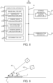
- FIG. 1 is a block diagram illustrating the configuration of the certificate determination system SYSa according to the first example embodiment.
- the certificate determination system SYSa includes a light source 1, a camera 2, which is one specific example of "imaging apparatus", and a determination server 3, which is one specific example of "certificate determination apparatus". At least one of the light source 1 and the camera 2 is capable of communicating with the determination server 3 through a communication network (or an arbitrary control line) 4.
- the communication network 4 may include a wired communication network, or may include a wireless communication network.
- the light source 1 and the camera 2 are used to capture an image of an identity certificate 5 of a user (see FIG. 2 ).
- the identity certificate 5 may refer to a physical document that can be used to prove who the user is (in other words, identity or authenticity).
- Examples of the identity certificate 5 include at least one of a driver's license, a passport (travel document), an insurance certificate, an individual number card, and an ID card.
- FIG. 2 An example of the light source 1 and the camera 2 capturing an image of the identity certificate 5 is illustrated in FIG. 2 .
- the light source 1 illuminates the identity certificate 5 with illumination light IL.
- the camera 2 captures an image of the identity certificate 5 illuminated with the illumination light II, from the light source 1.
- the camera 2 generates an image (hereinafter, referred to as "certificate image 21" as appropriate) in which the identity certificate 5 appears.
- the camera 2 transmits the generated certificate image 21 to the determination server 3 through the communication network 4.
- a positional relationship between the light source 1 and the camera 2 be fixed. In other words, it is preferable that the positional relationship between the light source 1 and the camera 2 not be changed. In such a case, it is preferable that the positional relationship between the light source 1 and the camera 2 be information known to the determination server 3.
- a single apparatus may include the light source 1 and the camera 2.
- a light source and a camera included in a single apparatus may be used for the light source 1 and the camera 2.
- a light source and a camera included in a smartphone or a tablet terminal may be used for the light source 1 and the camera 2.
- the positional relationship between the light source 1 and the camera 2 does not need to be fixed. In other words, the positional relationship between the light source 1 and the camera 2 may be changed. In such a case, it is also preferable that the positional relationship between the light source 1 and the camera 2 be information known to the determination server 3. In other words, when the positional relationship between the light source 1 and the camera 2 is changed, it is preferable that the determination server 3 be able to identify the changed positional relationship between the light source 1 and the camera 2.
- the determination server 3 performs certificate determination operation for determining, based on the certificate image 21, whether or not the identity certificate 5 appearing in the certificate image 21 is authentic. Specifically, based on the certificate image 21, the determination server 3 determines whether the certificate image 21 is an image generated by capturing an image of the real identity certificate 5 (hereinafter, referred to as "identity certificate 5_real” as appropriate), or is an image generated by capturing an image of a fake identity certificate 5 (hereinafter, referred to as "identity certificate 5_fake” as appropriate).
- the real identity certificate 5_real in the first example embodiment may refer to the identity certificate 5 itself (in other words, the original identity certificate 5).
- the fake identity certificate 5_fake in the first example embodiment may refer to an imitated identity certificate 5 that is not the identity certificate 5 itself.
- Examples of the identity certificate 5_fake include at least one of a document created by copying the identity certificate 5_real, and a display on which an image of the identity certificate 5_real appears.
- the determination server 3 generates shadow information related to a shadow 51 of the identity certificate 5 appearing the certificate image 21 and, based on the generated shadow information, determines whether or not the identity certificate 5 appearing in the certificate image 21 is authentic. Specifically, when the light source 1 illuminates the identity certificate 5_real with the illumination light IL as illustrated in FIG. 2 described above, a shadow 51 of the identity certificate 5_real is normally created. As a result, in the certificate image 21 in which the identity certificate 5_real appears, the shadow 51 of the identity certificate 5_real also appears, as illustrated in FIG. 3 that is an example of the certificate image 21. In contrast, the thickness of the identity certificate 5_fake, generally, differs from that of the identity certificate 5_real in many cases.
- the determination server 3 can determine, based on the shadow information, whether or not the identity certificate 5 appearing in the certificate image 21 is authentic.
- the determination server 3 includes a computation apparatus 31, a storage apparatus 32, and a communication apparatus 33.
- the computation apparatus 31, the storage apparatus 32, and the communication apparatus 33 are connected through a data bus 34.
- the computation apparatus 31 includes, for example, a CPU (Central Processing Unit).
- the computation apparatus 31 reads a computer program.
- the computation apparatus 31 may read the computer program stored in the storage apparatus 32.
- the computation apparatus 31 may read the computer program stored in a computer-readable non-transitory recording medium, by using an undepicted recording medium reading apparatus.
- the computation apparatus 31 may acquire (that is, may download or may read) the computer program, via the communication apparatus 33, from an undepicted apparatus placed outside of the determination server 3.
- the computation apparatus 31 executes the read computer program.
- a logical functional block is implemented for performing an operation (for example, the above-described certificate determination operation) to be performed by the determination server 3.
- the computation apparatus 31 can function as a controller for implementing the logical functional block for performing the operation to be performed by the determination server 3.
- FIG. 4 illustrates examples of the logical functional block implemented in the computation apparatus 31 to perform the certificate determination operation.
- an image analysis unit 311 and a determination unit 312, which is one specific example of "determination unit” are implemented in the computation apparatus 31.
- a shadow detection unit 313, which is one specific example of "generation unit” is implemented as a logical functional block. Operations of the image analysis unit 311 and the determination unit 312 will be described in detail later with reference to FIG. 5 and others.
- the storage apparatus 32 can store desired data.
- the storage apparatus 32 may temporarily store the computer program that is executed by the computation apparatus 31.
- the storage apparatus 32 may temporarily store data that is temporarily used by the computation apparatus 31 when the computation apparatus 31 executes the computer program.
- the storage apparatus 32 may store data that the determination server 3 retains on a long-term basis.
- the storage apparatus 32 may include at least one of a RAM (Random Access Memory), a ROM (Read Only Memory), a hard disk apparatus, a magneto-optical disk apparatus, an SSD (Solid State Drive), and a disk array apparatus.
- the communication apparatus 33 is capable of communicating with at least one of the light source 1 and the camera 2 through the communication network 4.
- the communication apparatus 33 may receive a certificate image 21 transmitted from the camera 2 through the communication network 4.
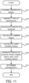
- FIG. 5 is a flowchart illustrating a flow of the certificate determination operation performed by the determination server 3 in the first example embodiment.
- the image analysis unit 311 acquires, by using the communication apparatus 33, a certificate image 21 transmitted from the camera 2 through the communication network 4 (step S 11).
- the shadow detection unit 313 in the image analysis unit 311 detects a shadow 51 of an identity certificate 5 appearing in the certificate image 21 (step S12). Specifically, the shadow detection unit 313, by analyzing the certificate image 21, identifies an image region (hereinafter, referred to as "certificate region 22", see FIG. 3 ) where the identity certificate 5 appears in the certificate image 21. Thereafter, the shadow detection unit 313, by analyzing the certificate image 21, determines whether or not there exists an image region (hereinafter, referred to as "shadow region 23", see FIG. 3 ) that extends outward from the certificate region 22 and in which the shadow 51 of the identity certificate 5 appears.
- the shadow detection unit 313 determines that the shadow 51 of the identity certificate 5 appears in the certificate image 21.
- the shadow detection unit 313 determines that the shadow 51 of the identity certificate 5 does not appear in the certificate image 21.
- a result of the detection of the shadow 51 by the shadow detection unit 313 in step S12 is outputted, as shadow information, from the shadow detection unit 313 to the determination unit 312.
- the shadow information including information related to presence or absence of the shadow 51 in the certificate image 21 is outputted from the shadow detection unit 313 to the determination unit 312.
- the determination unit 312 determines whether or not the identity certificate 5 appearing in the certificate image 21 is authentic (step S13). Specifically, as described above, the probability is relatively high that the thickness of an identity certificate 5_fake is thinner (particularly, much thinner) than the thickness of an identity certificate 5_real. Accordingly, as illustrated in FIG. 6 that is a side view illustrating the identity certificate 5_fake illuminated by the light source 1, it is highly probable that a shadow 51 of the identity certificate 5_fake is hardly created when the light source 1 illuminates the identity certificate 5 _fake with the illumination light IL.
- FIG. 7 that is a side view illustrating the identity certificate 5_real illuminated by the light source 1
- a shadow 51 of the identity certificate 5_fake is created when the light source 1 illuminates the identity certificate 5_real with the illumination light IL.
- the identity certificate 5_real has a certain thickness.
- it is highly probable that the shadow 51 of the identity certificate 5_real appears in the certificate image 21 in which the identity certificate 5_real appears.
- the determination unit 312 may determine that the identity certificate 5 appearing in the certificate image 21 is fake when the shadow 51 does not appear in the certificate image 21. In other words, the determination unit 312 may determine that the identity certificate 5_fake appears in the certificate image 21. In contrast, based on the shadow information, the determination unit 312 may determine that the identity certificate 5 appearing in the certificate image 21 is authentic when the shadow 51 appears in the certificate image 21. In other words, the determination unit 312 may determine that the identity certificate 5_real appears in the certificate image 21.
- the certificate determination system SYSa (particularly, the determination server 3) according to the first example embodiment can determine whether or not an identity certificate 5 appearing in a certificate image 21 is authentic, based on presence or absence of a shadow 51 of the identity certificate 5 appearing in the certificate image 21. Accordingly, the certificate determination system SYSa (particularly, the determination server 3) can determine whether or not the identity certificate 5 appearing in the certificate image 21 is authentic, at relatively low costs, compared to a case where a human determines, by visually checking the certificate image 21, whether or not the identity certificate 5 appearing in the certificate image 21 is authentic.
- certificate determination system SYS a certificate determination system SYS according to a second example embodiment is described.
- the certificate determination system SYS according to the second example embodiment is referred to as "certificate determination system SYSb".
- the certificate determination system SYSb according to the second example embodiment is different, compared to the certificate determination system SYSa according to the first example embodiment, in that the certificate determination system SYSb includes a determination server 3b in place of the determination server 3.
- Other characteristics of the certificate determination system SYSb may be the same as the other characteristics of the certificate determination system SYSa.
- the determination server 3b similarly to the determination server 3, generates shadow information related to a shadow 51 of an identity certificate 5 appearing in a certificate image 21, and performs certificate determination operation for determining, based on the generated shadow information, whether or not the identity certificate 5 appearing in the certificate image 21 is authentic. However, the determination server 3b generates the shadow information including information related a length L of the shadow 51 of the identity certificate 5. In such a respect, the determination server 3b is different from the determination server 3 that generates shadow information including information related to presence or absence of the shadow 51 of the identity certificate 5. Other characteristics of the determination server 3b may be the same as the other characteristics of the determination server 3.
- FIG. 8 is a block diagram illustrating a configuration of the determination server 3b in the second example embodiment.
- the determination server 3b is different, compared to the determination server 3, in that an image analysis unit 311b, in place of the image analysis unit 311, is implemented in the computation apparatus 31. Further, the determination server 3b is different, compared to the determination server 3, in that the storage apparatus 32 stores a shadow length DB 321b, which is one specific example of "estimated length data". Other components of the determination server 3b may be the same as the other components of the determination server 3.
- the image analysis unit 311b is different, compared to the image analysis unit 311, in that the image analysis unit 311b includes a certificate identification unit 314b, a camera angle calculation unit 315b, which is one specific example of "calculation unit”, a light source angle calculation unit 316b, which is one specific example of “calculation unit”, and a shadow length calculation unit 317b, which is one specific example of "generation unit”, in place of the shadow detection unit 313.
- the certificate identification unit 314b, the camera angle calculation unit 315b, the light source angle calculation unit 316b, and the shadow length calculation unit 317b will be described in detail later with reference to FIG. 10 and others, an outline of the operations is described below.
- the certificate identification unit 314b identifies, based on a certificate image 21, a type of an identity certificate 5 appearing in the certificate image 21.
- the camera angle calculation unit 315b calculates, based on the certificate image 21, an angle of the camera 2 (hereinafter, referred to as "camera angle ⁇ c") to the identity certificate 5.
- the light source angle calculation unit 316b calculates, based on the certificate image 21, an angle of the light source 1 (hereinafter, referred to as "light source angle ⁇ o”) to the identity certificate 5.
- the shadow length calculation unit 317b calculates, based on the certificate image 21, a length L of a shadow 51 of the identity certificate 5 appearing in the certificate image 21.
- the determination unit 312 determines, based on the camera angle ⁇ c calculated by the camera angle calculation unit 315b, the light source angle ⁇ o calculated by the light source angle calculation unit 316b, and the length L of the shadow 51 calculated by the shadow length calculation unit 317b, whether or not the identity certificate 5 appearing in the certificate image 21 is authentic.
- the camera angle ⁇ c is a parameter (in other words, an indicator) indicating a relative positional relationship between the camera 2 and the identity certificate 5.
- An example of the camera angle ⁇ c is illustrated in FIG. 9 .
- the camera angle ⁇ c may indicate an angle that a camera axis AC extending from the camera 2 forms with a surface of the identity certificate 5.
- the camera angle ⁇ c may indicate at least one of an angle that the camera axis AC forms with an axis along the surface of the identity certificate 5 (for example, an axis along any one of a short side and a long side of the identity certificate 5) in a vertical direction (see FIG.
- the camera axis AC may be an axis extending from the camera 2 toward a predetermined position on the identity certificate 5 (in the example illustrated in FIG. 9 , an upper end of the identity certificate 5).
- the camera axis AC may be an axis along an optical axis of an optical system (for example, a lens) included in the camera 2.
- the light source angle ⁇ o is a parameter (in other words, an indicator) indicating a relative positional relationship between the light source 1 and the identity certificate 5.
- An example of the light source angle ⁇ o is illustrated in FIG. 9 .
- the light source angle ⁇ o may indicate an angle that a light source axis OC extending from the light source 1 forms with the surface of the identity certificate 5.
- the light source angle ⁇ o may indicate at least one of an angle that the light source axis OC forms with an axis along the surface of the identity certificate 5 (for example, an axis along any one of the short side and the long side of the identity certificate 5) in the vertical direction (see FIG.
- the light source axis OC may be an axis extending from the light source 1 toward a predetermined position on the identity certificate 5 (in the example illustrated in FIG. 9 , the upper end of the identity certificate 5).
- the light source axis OC may be an axis along an optical axis of an optical system (for example, a lens) included in the light source 1.
- the light source axis OC may be an axis along a direction in which the illumination light IL emitted from the light source 1 travels.
- the shadow length DB 321b is a database that is referred to by the determination unit 312 in order to determine whether or not the identity certificate 5 appearing in the certificate image 21 is authentic. Specifically, the shadow length DB 321b is used to estimate a length L of a shadow 51 of the identity certificate 5 presumed to appear in the certificate image 21, based on the camera angle ⁇ c calculated by the camera angle calculation unit 315b and the light source angle ⁇ o calculated by the light source angle calculation unit 316b. Accordingly, the shadow length DB 321b is a database indicating a relationship between the camera angle ⁇ c and the light source angle ⁇ , and the length L of the shadow 51. An example of a data structure of the shadow length DB 321b is illustrated in FIG. 10 .
- the shadow length DB 321b includes a plurality of data records 322b.
- the length L of the shadow 51 of the identity certificate 5_real is associated with the camera angle ⁇ c and the light source angle ⁇ o.
- the shadow 51 here is a shadow presumed to appear in a certificate image 21 when it is assumed that the camera 2 captures an image of the real identity certificate 5_real illuminated by the light source 1 in a situation where the camera angle ⁇ c is a predetermined first angle and the light source angle ⁇ o is a predetermined second angle.
- each data record 322b associated with the camera angle ⁇ c and the light source angle ⁇ o is the logical length L (in other words, the length L in design) of the shadow 51 of the identity certificate 5_real presumed to appear in the certificate image 21 when it is assumed that the camera 2 disposed in such a manner that the camera angle ⁇ c is the predetermined second angle captures an image of the identity certificate 5_real illuminated by the light source 1 disposed in such a manner that the light source angle ⁇ o is the predetermined second angle.
- L the length L in design
- the shadow length DB 321b includes, for example, (i) a data record 322b indicating that when it is assumed that the camera 2 disposed in such a manner that the camera angle ⁇ c is an angle a1 captures an image of the identity certificate 5_real illuminated by the light source 1 disposed in such a manner that the light source angle ⁇ o is an angle a2, the length L of the shadow 51 of the identity certificate 5_real presumed to then appear in the certificate image 21 is a4, and (ii) a data record 322b indicating that when it is assumed that the camera 2 disposed in such a manner that the camera angle ⁇ c is an angle b 1 captures an image of the identity certificate 5_real illuminated by the light source 1 disposed in such a manner that the light source angle ⁇ o is an angle b2, the length L of the shadow 51 of the identity certificate 5_real presumed to then appear in the certificate image 21 is b4.
- the length L of the shadow 51 of the identity certificate 5_real may change also depending on a distance (that is, an interval) D between the light source 1 and the camera 2, in addition to the light source angle ⁇ o and the camera angle ⁇ c. Accordingly, in each data record 322b, the length L of the shadow 51 of the identity certificate 5_real may be associated with the camera angle ⁇ c, the light source angle ⁇ , and the distance D between the light source 1 and the camera 2.
- the shadow 51 here is a shadow presumed to appear in a certificate image 21 when it is assumed that the camera 2 captures an image of the real identity certificate 5_real illuminated by the light source 1 in a situation where the camera angle ⁇ c is the predetermined first angle, the light source angle ⁇ o is the predetermined second angle, and the distance D between the light source 1 and the camera 2 is a predetermined distance.
- the "distance" in the second example embodiment may include at least one of a distance along an X axis, a distance along a Y axis, and a distance along a Z axis in an XYZ coordinate system with the X, Y, and Z axes being mutually orthogonal. In the example illustrated in FIG.
- the shadow length DB 321b includes, for example, (i) the data record 322b indicating that when it is assumed that the camera 2 disposed in such a manner that the camera angle ⁇ c is the angle a1 and the camera 2 is a distance a3 away from the light source 1 captures an image of the identity certificate 5_real illuminated by the light source 1 disposed in such a manner that the light source angle ⁇ o is the angle a2, the length L of the shadow 51 of the identity certificate 5_real presumed to then appear in the certificate image 21 is a4, and (ii) the data record 322b indicating that when it is assumed that the camera 2 disposed in such a manner that the camera angle ⁇ c is the angle b1 and the camera 2 is a distance b3 away from the light source 1 captures an image of the identity certificate 5_real illuminated by the light source 1 disposed in such a manner that the light source angle ⁇ o is the angle b2, the length L of the shadow 51 of the identity certificate 5_real presumed to
- the length L of the shadow 51 of the identity certificate 5_real may change also depending on the thickness of the identity certificate 5_real, in addition to the light source angle ⁇ o and the camera angle ⁇ c.
- the thickness of the identity certificate 5_real depends on a type of the identity certificate 5_real.
- the thickness of a driver's license which is an example of the identity certificate 5_real
- the shadow length DB 321b may include a data record 322b, for each type of identity certificate 5_real.
- the shadow length DB 321b may include a data record 322b indicating the length of the shadow 51 of the identity certificate 5_real of a first type, and a data record 322b indicating the length of the shadow 51 of the identity certificate 5_real of a second type that is different from the first type.
- the shadow length DB 321b includes data records 322b each indicating the length L of the shadow 51 of a driver's license, which is an example of the identity certificate 5_real, and data records 322b each indicating the length L of the shadow 51 of a passport, which is an example of the identity certificate 5_real.
- the determination unit 312 estimates a length L of a shadow 51 of the identity certificate 5 (that is, an estimated value of the length L of the shadow 51) presumed to appear in the certificate image 21. In other words, the determination unit 312 estimates the length L of the shadow 51 (that is, an estimated value of the length L of the shadow 51) appearing in the certificate image 21 when it is assumed that the real identity certificate 5_real appears in the certificate image 21.
- the determination unit 312 determines whether or not the identity certificate 5 appearing in the certificate image 21 is authentic.
- FIG. 11 is a flowchart illustrating a flow of the certificate determination operation performed by the determination server 3 in the second example embodiment.
- the image analysis unit 31 by using the communication apparatus 33, acquires a certificate image 21 transmitted from the camera 2 through the communication network 4 (step S21).
- the certificate identification unit 314b in the image analysis unit 311 identifies a type of an identity certificate 5 appearing in the certificate image 21 (step S22).
- the certificate identification unit 314b by analyzing the certificate image 21, identifies the type of the identity certificate 5 appearing in the certificate image 21 (step S22).
- the certificate identification unit 314b may identify the type of the identity certificate 5, based on a characteristic (for example, at least one of size, color, and shape) of the identity certificate 5 appearing in the certificate image 21.
- the certificate identification unit 314b may identify the type of the identity certificate 5 by performing, on the certificate image 21, a pattern matching process using a template in conformity with a format of the identity certificate 5.
- the certificate identification unit 314b similarly to the shadow detection unit 313 in the first example embodiment, may identify an image region (that is, a certificate region 22) where the identity certificate 5 appears in the certificate image 21. Note that when the type of the identity certificate 5 appearing in the certificate image 21 is already known to the determination server 3, the image analysis unit 311 does not need to identify the type of the identity certificate 5. In such a case, the image analysis unit 311 does not need to include the certificate identification unit 314b.
- the shadow length calculation unit 317b calculates a length L of a shadow 51 of the identity certificate 5 appearing in the certificate image 21 (step S23).
- the size of the identity certificate 5 is a unique value depending on the type of the identity certificate 5. Accordingly, the size of the identity certificate 5 can be used for a reference length when the length L of the shadow 51 is calculated. Accordingly, first, the shadow length calculation unit 317b identifies a size (for example, a length of at least one of a long side and a short side) of the identity certificate 5, based on the type of the identity certificate 5 identified by the certificate identification unit 314b.
- the size of the identity certificate 5 is equivalent to the size of the certificate region 22 in the certificate image 21.
- the shadow length calculation unit 317b similarly to the shadow detection unit 313 described in the first example embodiment, detects an image region (that is, a shadow region 23) where a shadow extending outward from the certificate region 22 appears. Thereafter, the shadow length calculation unit 317b calculates a size of the detected shadow region 23, based on the size of the certificate region 22.
- the size of the shadow region 23 may be, for example, a distance from one end portion of the shadow region 23 adjacent to the certificate region 22 to the other end portion of the shadow region 23 far from the certificate region 22, along a direction in which the illumination light IL travels.
- the calculated size of the shadow region 23 is used for the length L of the shadow 51.
- a result of the calculation of the length L of the shadow 51 by the shadow length calculation unit 317b in step S23 is outputted, as shadow information, from the shadow length calculation unit 317b to the determination unit 312.
- the shadow information including information related to the length L of the shadow 51 in the certificate image 21 is outputted from the shadow length calculation unit 317b to the determination unit 312.
- the camera angle calculation unit 315b calculates an angle of the camera 2 (that is, a camera angle ⁇ c) to the identity certificate 5 (step S24). Specifically, when the camera angle ⁇ c is changed, a change occurs in the ratio between the lengths of two intersecting sides (for example, the long side and the short side) of the identity certificate 5 appearing in the certificate image 21.
- FIG. 12 illustrates a certificate image 21 generated in a situation where the camera angle ⁇ c between the camera axis AC and the surface of the identity certificate 5 is relatively large
- the camera angle calculation unit 315b may calculate the camera angle ⁇ c, based on the ratio between the lengths of the two intersecting sides of the identity certificate 5.
- the camera angle ⁇ c calculated here corresponds to a camera angle ⁇ c at a time when the camera 2 captures the image of the identity certificate 5.
- the camera angle ⁇ c calculated in step S24 is outputted from the camera angle calculation unit 315b to the determination unit 312.
- the light source angle calculation unit 316b calculates an angle of the light source 1 (that is, a light source angle ⁇ o) to the identity certificate 5 (step S25). Specifically, in a case where the positional relationship between the light source 1 and the camera 2 is fixed as described above, when the camera angle ⁇ c is determined, the light source angle ⁇ o is also uniquely determined. Alternatively, in a case where the positional relationship between the light source 1 and the camera 2 is information known to the determination server 3 even if the positional relationship between the light source 1 and the camera 2 is not fixed, when the camera angle ⁇ c is determined, the light source angle ⁇ o is also uniquely determined.
- the light source angle calculation unit 316b can calculate the light source angle ⁇ , based on the camera angle ⁇ c (further, based also on the positional relationship between the light source 1 and the camera 2 as necessary).
- the light source angle ⁇ o calculated here corresponds to a light source angle ⁇ o at the time when the camera 2 captures the image of the identity certificate 5.
- the light source angle ⁇ o calculated in step S25 is outputted from the light source angle calculation unit 316b to the determination unit 312.
- the determination unit 312 estimates a length L of a shadow 51 of the identity certificate 5 presumed to appear in the certificate image 21 (step S26). In other words, the determination unit 312 estimates the length L of the shadow 51 (that is, an estimated value of the length L of the shadow 51) appearing in the certificate image 21 when it is assumed that the real identity certificate 5_real appears in the certificate image 21.
- the determination unit 312 estimates the logical length L (in other words, the length L in design) of the shadow 51 of the identity certificate 5_real presumed to appear in the certificate image 21 when it is assumed that the camera 2 disposed at a position based on the camera angle ⁇ c calculated in step S24 captures an image of the real identity certificate 5_real illuminated by the light source 1 disposed at a position based on the light source angle ⁇ o calculated in step S25.
- the determination unit 312 extracts, from the shadow length DB 321b, a data record 322b corresponding to the camera angle ⁇ c calculated in step S24 and the light source angle ⁇ o calculated in step S25. Thereafter, the determination unit 312 uses a length L of the shadow 51 indicated in the extracted data record 322b for the estimated value of the length L of the shadow 51.
- the determination unit 312 may identify a distance D between the light source 1 and the camera 2, and may extract, from the shadow length DB 321b, a data record 322b corresponding to the identified distance D.
- the distance D between the light source 1 and the camera 2 is a fixed value when the positional relationship between the light source 1 and the camera 2 is fixed.
- the distance D between the light source 1 and the camera 2 is a variable value.
- the determination server 3 can identify the distance D between the light source 1 and the camera 2.
- the determination unit 312 determines whether or not the identity certificate 5 appearing in the certificate image 21 is authentic (step S27). Specifically, as illustrated in FIG. 14 , when the identity certificate 5 appearing in the certificate image 21 is authentic (that is, the identity certificate 5_real), the calculated value L1 of the length L of the shadow 51 is approximately the same value as the estimated value of the length L of the shadow 51 (that is, the logical length L). In contrast, as illustrated FIG.
- the calculated value L2 of the length L of the shadow 51 is a different value from the estimated value of the length L (that is, the logical length L) of the shadow 51.
- the calculated value of the length L of the shadow 51 indicates the length L of the shadow 51 of the identity certificate 5_fake that has a different thickness from the thickness of the identity certificate 5_real.
- the calculated value L2 of the length L of the shadow 51 of the identity certificate 5_fake is a different value from the length L1 of the shadow 51 of the identity certificate 5_real (alternatively, the estimated value of the length L of the shadow 51 corresponding to the logical value of the length L1 of the shadow 51 of the identity certificate 5_real). Accordingly, the determination unit 312 can determine whether or not the identity certificate 5 appearing in the certificate image 21 is authentic, by comparing the calculated value of the length L of the shadow 51 calculated in step S23 and the estimated value of the length L of the shadow 51 estimated in step S26.
- the determination unit 312 may determine that the identity certificate 5 appearing in the certificate image 21 is not authentic.
- the determination unit 312 may determine that the identity certificate 5 appearing in the certificate image 21 is authentic.
- first and second allowances may be set to appropriate values that make it possible to distinguish, based on the length L of the shadow 51 of the identity certificate 5 appearing in the certificate image 21, between a state where the identity certificate 5 appearing in the certificate image 21 is authentic and a state where the identity certificate 5 appearing in the certificate image 21 is not authentic.
- Such first and second allowances may be set by experiment or simulation.
- the first allowance may be the same as, or may be different from, the second allowance.
- the certificate determination system SYSb (particularly, the determination server 3b) according to the second example embodiment can determine whether or not an identity certificate 5 appearing in a certificate image 21 is authentic, based on the length L of a shadow 51 of the identity certificate 5 appearing in the certificate image 21. Accordingly, the certificate determination system SYSb (particularly, the determination server 3b) can determine whether or not the identity certificate 5 appearing in the certificate image 21 is authentic, at relatively low costs, compared to a case where a human determines, by visually checking the certificate image 21, whether or not the identity certificate 5 appearing in the certificate image 21 is authentic.
- the determination server 3b determines that the identity certificate 5 appearing in the certificate image 21 is not authentic when the length L of the shadow 51 appearing in the certificate image 21 is different from the length L of a shadow 51 of the real identity certificate 5_real. Accordingly, the certificate determination system SYSb (particularly, the determination server 3b) can determine whether or not the identity certificate 5 appearing in the certificate image 21 is authentic, with higher accuracy.
- the determination server 3b may generate shadow information including information related to a change (typically, time-series changes) in the length L of a shadow 51 of the identity certificate 5. Specifically, the determination server 3b acquires a plurality of certificate images 21 transmitted from the camera 2. The plurality of certificate images 21 are generated by repeating an operation, by the camera 2, of capturing an image of the identity certificate 5, and an operation of changing a positional relationship between the identity certificate 5 and at least one of the light source 1 and the camera 2. In other words, in the first modified example, each time the positional relationship between the identity certificate 5 and at least one of the light source 1 and the camera 2 is changed, the camera 2 captures an image of the identity certificate 5.
- a change typically, time-series changes
- the plurality of certificate images 21 may be a plurality of images included in a video.
- the shadow length calculation unit 317b in the determination server 3b calculates a length L of a shadow 51 of the identity certificate 5 appearing in each of the plurality of certificate images 21.
- the shadow length calculation unit 317b can calculate time-series changes in the length L of the shadow 51. Results of the calculation of the length L of the shadow 51 by the shadow length calculation unit 317b are outputted, as shadow information, from the shadow length calculation unit 317b to the determination unit 312.
- the camera angle calculation unit 315b calculates a camera angle ⁇ c, based on each of the plurality of certificate images 21. As a result, the camera angle calculation unit 315b calculates time-series changes in the camera angle ⁇ c. Similarly, the light source angle calculation unit 316b calculates time-series changes in the light source angle ⁇ , based on the time-series changes in the camera angle ⁇ c.
- the determination unit 312 estimates time-series changes in the length L of a shadow 51 of the identity certificate 5 presumed to appear in the certificate images 21. In other words, the determination unit 312 estimates time-series changes in the length L of the shadow 51 (that is, estimated values of time-series changes in the length L of the shadow 51) appearing in the certificate images 21 when it is assumed that the real identity certificate 5_real appears in the certificate images 21.
- the determination unit 312 determines whether or not the identity certificate 5 appearing in the certificate images 21 is authentic, by comparing the calculated values of the time-series changes in the length L of the shadow 51 calculated by the shadow length calculation unit 317b and the estimated values of the time-series changes in the length L of the shadow 51 estimated by the determination unit 312.
- the determination unit 312 determines whether or not the identity certificate 5 appearing in the certificate images 21 is authentic, by comparing a pattern of changes in the length L of the shadow 51 actually appearing in the certificate images 21 (hereinafter, referred to as "actual change pattern") and a pattern of changes in the length L of the shadow 51 presumed to appear in the certificate images 21 (hereinafter, referred to as "presumed change pattern"). For example, when a degree of similarity between the actual change pattern of the length L of the shadow 51 and the presumed change pattern of the length L of the shadow 51 is higher than a first threshold value, the determination unit 312 may determine that the identity certificate 5 appearing in the certificate images 21 is authentic.
- actual change pattern a pattern of changes in the length L of the shadow 51 actually appearing in the certificate images 21
- predetermined change pattern a pattern of changes in the length L of the shadow 51 presumed to appear in the certificate images 21
- the determination unit 312 may determine that the identity certificate 5 appearing in the certificate images 21 is not authentic.
- first and second threshold values may be set to appropriate values that make it possible to distinguish, based on a pattern of changes (that is, time-series changes) in the length L of the shadow 51 of the identity certificate 5 appearing in the certificate images 21, between a state where the identity certificate 5 appearing in the certificate images 21 is authentic and a state where the identity certificate 5 appearing in the certificate images 21 is not authentic.
- Such first and second threshold values may be set by experiment or simulation.
- the first threshold value may be the same as, or may be different from, the second threshold value.
- the determination server 3b performs the certificate determination operation by using time-series changes in the length L of the shadow 51.
- the determination server 3b may perform the certificate determination operation by using arbitrary time-series changes in the shadow 51.
- the determination server 3b may perform the certificate determination operation by using time-series changes in an arbitrary parameter indicating a state of the shadow 51. For example, when the positional relationship between the identity certificate 5 and at least one of the light source 1 and the camera 2 is changed, a change may occur in a direction in which the shadow 51 extends from the identity certificate 5 (that is, the direction of the shadow 51). For example, FIG.
- the determination server 3b may perform the certificate determination operation by using time-series changes in the direction in which the shadow 51 extends.
- the shadow length calculation unit 317b in the determination server 3b may calculate a direction in which the shadow 51 of the identity certificate 5 appearing in each of the plurality of certificate images 21 extends.
- the shadow length calculation unit 317b can calculate time-series changes in the direction in which the shadow 51 extends.
- the determination unit 312 estimates time-series changes in the direction in which a shadow 51 of the identity certificate 5 presumed to appear in the certificate images 21 extends, based on the time-series changes in the camera angle ⁇ c, the time-series changes in the light source angle ⁇ , and the shadow length DB 321b.
- the direction in which the shadow 51 of the identity certificate 5_real presumed to appear in the certificate image 21 extends be associated with the camera angle ⁇ c and the light source angle ⁇ o in each data record 322b in the shadow length DB 321b, as illustrated in FIG.
- the determination unit 312 may determine whether or not the identity certificate 5 appearing in the certificate images 21 is authentic, by comparing calculated values of the time-series changes in the direction in which the shadow 51 extends, calculated by the shadow length calculation unit 317b, and estimated values of the time-series changes in the direction in which the shadow 51 extends, estimated by the determination unit 312. For example, when a degree of similarity between an actual change pattern of the direction in which the shadow 51 extends and a presumed change pattern of the direction in which the shadow 51 extends is higher than a third threshold value, the determination unit 312 may determine that the identity certificate 5 appearing in the certificate images 21 is authentic.
- the determination unit 312 may determine that the identity certificate 5 appearing in the certificate images 21 is not authentic.
- the third and fourth threshold values may be set to appropriate values that make it possible to distinguish, based on a pattern of changes in the direction in which the shadow 51 of the identity certificate 5 appearing in the certificate images 21 extends, between a state where the identity certificate 5 appearing in the certificate images 21 is authentic and a state where the identity certificate 5 appearing in the certificate images 21 is not authentic.
- Such third and fourth threshold values may be set by experiment or simulation.
- the third threshold value may be the same as, or may be different from, the fourth threshold value.
- step S26 in FIG. 11 the determination unit 312 estimates the length L of the shadow 51 of the identity certificate 5, based on the camera angle ⁇ c, the light source angle ⁇ , and the shadow length DB 321b. Thereafter, in step S27 in FIG. 11 , the determination unit 312 determines whether or not the identity certificate 5 appearing in the certificate image 21 is authentic, by comparing a calculated value of the length L of the shadow 51 calculated by the shadow length calculation unit 317b in step S23 and an estimated value of the length L of the shadow 51 estimated by the determination unit 312 in step S26.
- the determination unit 312 may estimates, based on the length L of the shadow 51 calculated by the shadow length calculation unit 317b in step S23 and the shadow length DB 321b, a light source angle ⁇ o that the light source 1 is presumed to form with the identity certificate 5_real when it is assumed that the shadow 51 having the length L calculated by the shadow length calculation unit 317b appears in the certificate image 21. In other words, the determination unit 312 may estimate an estimated value of the light source angle ⁇ o.
- the determination unit 312 may determine whether or not the identity certificate 5 appearing in the certificate image 21 is authentic, based on the actual calculated value of the light source angle ⁇ o calculated in step S25, and the estimated value of the light source angle ⁇ o estimated in step S26.
- the estimated value of the light source angle ⁇ o estimated in step S26 is approximately the same value as the actual calculated value of the light source angle ⁇ o.
- the estimated value of the light source angle ⁇ o estimated in step S26 is a different value from the actual calculated value of the light source angle ⁇ o.
- the determination unit 312 can determine whether or not the identity certificate 5 appearing in the certificate image 21 is authentic, by comparing the calculated value of the light source angle ⁇ o calculated in step S24 and the estimated value of the light source angle ⁇ o estimated in step S26.
- the determination unit 312 can determine whether or not the identity certificate 5 appearing in the certificate image 21 is authentic, by determining whether or not the actual light source angle ⁇ o calculated in step S24 seems to be authentic, on the basis of an ideal light source angle ⁇ o (in other words, a light source angle ⁇ o in design) at which a shadow 51 having the length L calculated in step S23 is created. For example, when a difference between the calculated value of the light source angle ⁇ o and the estimated value of the light source angle ⁇ o is more than a predetermined third allowance (that is, the calculated value of the light source angle ⁇ o is greatly different from the estimated value of the light source angle ⁇ o), the determination unit 312 may determine that the identity certificate 5 appearing in the certificate image 21 is not authentic.
- a predetermined third allowance that is, the calculated value of the light source angle ⁇ o is greatly different from the estimated value of the light source angle ⁇ o
- the determination unit 312 may determine that the identity certificate 5 appearing in the certificate image 21 is authentic.
- the third and the fourth allowances may be set to appropriate values that make it possible to distinguish, based on the light source angle ⁇ , between a state where the identity certificate 5 appearing in the certificate image 21 is authentic and a state where the identity certificate 5 appearing in the certificate image 21 is not authentic.
- Such third and fourth allowances may be set by experiment or simulation.
- the third allowance may be the same as, or may be different from, the fourth allowance.
- the camera angle calculation unit 315b does not need to calculate a camera angle ⁇ c.
- the image analysis unit 311 does not need to include the camera angle calculation unit 315b.
- the determination server 3b performs the certificate determination operation by using the camera angle ⁇ c.
- the camera angle ⁇ c is one specific example of a parameter indicating the relative positional relationship between the camera 2 and the identity certificate 5.
- the determination server 3b may perform the certificate determination operation by using an arbitrary parameter indicating the relative positional relationship between the camera 2 and the identity certificate 5, in addition to, or in place of, the camera angle ⁇ c.
- the arbitrary parameter indicating the relative positional relationship between the camera 2 and the identity certificate 5 include at least one of a distance from the identity certificate 5 to the camera 2, and an azimuth direction in which the camera 2 is positioned relative to the identity certificate 5.
- the determination server 3b performs the certificate determination operation by using the light source angle ⁇ o.
- the light source angle ⁇ o is one specific example of a parameter indicating the relative positional relationship between the light source 1 and the identity certificate 5.
- the determination server 3b may perform the certificate determination operation by using an arbitrary parameter indicating the relative positional relationship between the light source 1 and the identity certificate 5, in addition to, or in place of, the light source angle ⁇ o.
- the arbitrary parameter indicating the relative positional relationship between the light source 1 and the identity certificate 5 include at least one of a distance from the identity certificate 5 to the light source 1, and an azimuth direction in which the light source 1 is positioned relative to the identity certificate 5.
- certificate determination system SYSc is different, compared to the certificate determination system SYSa according to the first example embodiment, in that the certificate determination system SYSc includes a determination server 3c in place of the determination server 3.
- Other characteristics of the certificate determination system SYSc may be the same as the other characteristics of the certificate determination system SYSa. Accordingly, in the following, a description is given of the determination server 3c in the third example embodiment, focused mainly on differences between the determination server 3c and the determination server 3, with reference to FIG. 18.
- FIG. 18 is a block diagram illustrating a configuration of the determination server 3c in the third example embodiment.
- the determination server 3c is different, compared to the determination server 3, in that a light source control unit 318c, which is one specific example of "control unit”, is implemented as a logical processing block in the computation apparatus 31.
- Other components of the determination server 3c may be the same as the other components of the determination server 3.
- the light source control unit 318c is capable of controlling the light source 1 through the communication network 4.
- the light source control unit 318c may control a characteristic (for example, intensity) of the illumination light IL, by controlling the light source 1.
- the light source control unit 318c may control the characteristic of the illumination light II, in such a manner that a shadow 51 appropriately appears in a certificate image 21, compared to the shadow 51 before the characteristic of the illumination light II, is controlled.
- a state where "a shadow 51 appropriately appears in a certificate image 21" may refer to, for example, a state where a shadow 51 appears in a certificate image 21 to such an extent that the image analysis unit 311 can appropriately detect the shadow 51.
- the state where "a shadow 51 appropriately appears in a certificate image 21" may refer to a state where a shadow 51 clearly appears in a certificate image 21 to such an extent that a contrast between a shadow region 23 where the shadow 51 appears and an image region other than the shadow region 23 is equal to or more than a certain amount.
- Such a certificate determination system SYSc according to the third example embodiment can appropriately detect the shadow 51 appearing in the certificate image 21, while achieving advantageous effects similar to the above-described advantageous effects that can be achieved by the certificate determination system SYSa according to the first example embodiment.
- the light source control unit 318c may control the camera 2 through the communication network 4, in addition to, or in place of, controlling the light source 1.
- the light source control unit 318c may control an optical characteristic (for example, sensitivity) of the camera 2, by controlling the camera 2.
- the light source control unit 318c may control the optical characteristic of the camera 2 in such a manner that a shadow 51 appropriately appears in a certificate image 21, compared to the shadow 51 before the optical characteristic of the camera 2 is controlled.
- the certificate determination system SYSc can also appropriately detect the shadow 51 appearing in the certificate image 21, while achieving advantageous effects similar to the above-described advantageous effects that can be achieved by the certificate determination system SYSa according to the first example embodiment.
Landscapes
- Engineering & Computer Science (AREA)
- Physics & Mathematics (AREA)
- General Physics & Mathematics (AREA)
- Theoretical Computer Science (AREA)
- Computer Vision & Pattern Recognition (AREA)
- Multimedia (AREA)
- Health & Medical Sciences (AREA)
- General Health & Medical Sciences (AREA)
- Toxicology (AREA)
- Quality & Reliability (AREA)
- Software Systems (AREA)
- Collating Specific Patterns (AREA)
- Image Analysis (AREA)
Applications Claiming Priority (1)
| Application Number | Priority Date | Filing Date | Title |
|---|---|---|---|
| PCT/JP2020/037414 WO2022070381A1 (ja) | 2020-10-01 | 2020-10-01 | 証明書判定装置、証明書判定方法及び記録媒体 |
Publications (3)
| Publication Number | Publication Date |
|---|---|
| EP4224411A1 EP4224411A1 (en) | 2023-08-09 |
| EP4224411A4 EP4224411A4 (en) | 2023-12-06 |
| EP4224411B1 true EP4224411B1 (en) | 2024-12-25 |
Family
ID=80950069
Family Applications (1)
| Application Number | Title | Priority Date | Filing Date |
|---|---|---|---|
| EP20956309.7A Active EP4224411B1 (en) | 2020-10-01 | 2020-10-01 | Certificate determination device, certificate determination method, and recording medium |
Country Status (4)
| Country | Link |
|---|---|
| US (1) | US20230342900A1 (https=) |
| EP (1) | EP4224411B1 (https=) |
| JP (1) | JP7435811B2 (https=) |
| WO (1) | WO2022070381A1 (https=) |
Families Citing this family (3)
| Publication number | Priority date | Publication date | Assignee | Title |
|---|---|---|---|---|
| US12519659B2 (en) * | 2020-10-02 | 2026-01-06 | Nec Corporation | Information processing device, information processing method, and recording medium |
| JP7815984B2 (ja) * | 2022-05-11 | 2026-02-18 | 大日本印刷株式会社 | 真贋判定装置、プログラムおよびスキャナ |
| CN117011516B (zh) * | 2022-09-27 | 2026-02-27 | 腾讯科技(深圳)有限公司 | 证件鉴伪处理方法、装置、设备、存储介质和程序产品 |
Family Cites Families (3)
| Publication number | Priority date | Publication date | Assignee | Title |
|---|---|---|---|---|
| AT307109B (de) * | 1972-02-03 | 1973-05-10 | Internat Security Systems S A | Verfahren und Anordnung zum Erkennen der Echtheit von Wertpapieren u.dgl. |
| JP4451426B2 (ja) * | 2006-09-21 | 2010-04-14 | コニカミノルタエムジー株式会社 | 複写撮影装置、idカード作成システム及びidカード作成方法 |
| JP7168194B2 (ja) * | 2018-05-23 | 2022-11-09 | Necソリューションイノベータ株式会社 | 偽造判定方法、プログラム、記録媒体および偽造判定装置 |
-
2020
- 2020-10-01 WO PCT/JP2020/037414 patent/WO2022070381A1/ja not_active Ceased
- 2020-10-01 EP EP20956309.7A patent/EP4224411B1/en active Active
- 2020-10-01 JP JP2022553373A patent/JP7435811B2/ja active Active
- 2020-10-01 US US18/028,007 patent/US20230342900A1/en active Pending
Also Published As
| Publication number | Publication date |
|---|---|
| US20230342900A1 (en) | 2023-10-26 |
| WO2022070381A1 (ja) | 2022-04-07 |
| EP4224411A4 (en) | 2023-12-06 |
| JPWO2022070381A1 (https=) | 2022-04-07 |
| EP4224411A1 (en) | 2023-08-09 |
| JP7435811B2 (ja) | 2024-02-21 |
Similar Documents
| Publication | Publication Date | Title |
|---|---|---|
| US20230086552A1 (en) | Image processing method and apparatus, device, storage medium, and computer program product | |
| EP4224411B1 (en) | Certificate determination device, certificate determination method, and recording medium | |
| KR102138082B1 (ko) | 다수의 이미지 일치성을 바탕으로 보험클레임 사기 방지를 실현하는 방법, 시스템, 기기 및 판독 가능 저장매체 | |
| CN106899567B (zh) | 用户核身方法、装置及系统 | |
| US11314966B2 (en) | Facial anti-spoofing method using variances in image properties | |
| EP3642756A1 (en) | Detecting artificial facial images using facial landmarks | |
| CN112381105B (zh) | 滑块校验的自动化处理方法、装置、设备及介质 | |
| KR20220126463A (ko) | 원본 증명 방법, 및 이를 위한 장치 | |
| US11872832B2 (en) | Texture-based authentication of digital identity documents | |
| CN111881740A (zh) | 人脸识别方法、装置、电子设备及介质 | |
| CN111753722B (zh) | 一种基于特征点类型的指纹识别方法及装置 | |
| US20260046285A1 (en) | Enhanced authentication using a secure document | |
| CN108596127A (zh) | 一种指纹识别方法、身份验证方法及装置和身份核验机 | |
| JP2006099326A (ja) | 平面4指画像判定装置、平面4指画像判定方法及び平面4指画像判定プログラム | |
| KR20230060439A (ko) | 실물 촬영 이미지 여부 식별 방법 및 시스템 | |
| CN113886627B (zh) | 一种基于信息同步的移动通信系统 | |
| KR20030005113A (ko) | 홍채를 이용한 신원 확인 시스템 및 방법과 그 방법에대한 컴퓨터 프로그램 소스를 저장한 기록매체 | |
| CN113518217A (zh) | 对象识别方法、装置、服务器及介质 | |
| CN118887689A (zh) | 手写电子签名的真实性验证方法、装置 | |
| KR20230156823A (ko) | 지문 식별 방법, 장치, 전자 장치 및 저장 매체 | |
| JP6442873B2 (ja) | 指紋画像処理装置、指紋画像処理方法及びプログラム | |
| US20220406094A1 (en) | Authentication apparatus, authentication method and recording medium | |
| TW202242681A (zh) | 辨識影像中之動作以判斷目標是否為活體之系統及方法 | |
| CN116740789B (zh) | 目标检测模型训练方法、装置、设备、介质及程序产品 | |
| CN116469180B (zh) | 识别方法、装置、计算机设备和存储介质 |
Legal Events
| Date | Code | Title | Description |
|---|---|---|---|
| STAA | Information on the status of an ep patent application or granted ep patent |
Free format text: STATUS: THE INTERNATIONAL PUBLICATION HAS BEEN MADE |
|
| PUAI | Public reference made under article 153(3) epc to a published international application that has entered the european phase |
Free format text: ORIGINAL CODE: 0009012 |
|
| STAA | Information on the status of an ep patent application or granted ep patent |
Free format text: STATUS: REQUEST FOR EXAMINATION WAS MADE |
|
| 17P | Request for examination filed |
Effective date: 20230330 |
|
| AK | Designated contracting states |
Kind code of ref document: A1 Designated state(s): AL AT BE BG CH CY CZ DE DK EE ES FI FR GB GR HR HU IE IS IT LI LT LU LV MC MK MT NL NO PL PT RO RS SE SI SK SM TR |
|
| A4 | Supplementary search report drawn up and despatched |
Effective date: 20231103 |
|
| RIC1 | Information provided on ipc code assigned before grant |
Ipc: G06V 30/18 20220101ALI20231027BHEP Ipc: G07D 7/20 20160101ALI20231027BHEP Ipc: G07D 7/12 20160101ALI20231027BHEP Ipc: G07D 7/164 20160101ALI20231027BHEP Ipc: G06T 7/00 20170101AFI20231027BHEP |
|
| DAV | Request for validation of the european patent (deleted) | ||
| DAX | Request for extension of the european patent (deleted) | ||
| RIC1 | Information provided on ipc code assigned before grant |
Ipc: G06V 30/18 20220101ALI20240604BHEP Ipc: G07D 7/20 20160101ALI20240604BHEP Ipc: G07D 7/12 20160101ALI20240604BHEP Ipc: G07D 7/164 20160101ALI20240604BHEP Ipc: G06T 7/00 20170101AFI20240604BHEP |
|
| GRAP | Despatch of communication of intention to grant a patent |
Free format text: ORIGINAL CODE: EPIDOSNIGR1 |
|
| STAA | Information on the status of an ep patent application or granted ep patent |
Free format text: STATUS: GRANT OF PATENT IS INTENDED |
|
| INTG | Intention to grant announced |
Effective date: 20240719 |
|
| GRAS | Grant fee paid |
Free format text: ORIGINAL CODE: EPIDOSNIGR3 |
|
| GRAA | (expected) grant |
Free format text: ORIGINAL CODE: 0009210 |
|
| STAA | Information on the status of an ep patent application or granted ep patent |
Free format text: STATUS: THE PATENT HAS BEEN GRANTED |
|
| AK | Designated contracting states |
Kind code of ref document: B1 Designated state(s): AL AT BE BG CH CY CZ DE DK EE ES FI FR GB GR HR HU IE IS IT LI LT LU LV MC MK MT NL NO PL PT RO RS SE SI SK SM TR |
|
| REG | Reference to a national code |
Ref country code: GB Ref legal event code: FG4D |
|
| REG | Reference to a national code |
Ref country code: CH Ref legal event code: EP |
|
| REG | Reference to a national code |
Ref country code: DE Ref legal event code: R096 Ref document number: 602020043883 Country of ref document: DE |
|
| REG | Reference to a national code |
Ref country code: IE Ref legal event code: FG4D |
|
| REG | Reference to a national code |
Ref country code: LT Ref legal event code: MG9D |
|
| PG25 | Lapsed in a contracting state [announced via postgrant information from national office to epo] |
Ref country code: HR Free format text: LAPSE BECAUSE OF FAILURE TO SUBMIT A TRANSLATION OF THE DESCRIPTION OR TO PAY THE FEE WITHIN THE PRESCRIBED TIME-LIMIT Effective date: 20241225 |
|
| PG25 | Lapsed in a contracting state [announced via postgrant information from national office to epo] |
Ref country code: FI Free format text: LAPSE BECAUSE OF FAILURE TO SUBMIT A TRANSLATION OF THE DESCRIPTION OR TO PAY THE FEE WITHIN THE PRESCRIBED TIME-LIMIT Effective date: 20241225 |
|
| PG25 | Lapsed in a contracting state [announced via postgrant information from national office to epo] |
Ref country code: BG Free format text: LAPSE BECAUSE OF FAILURE TO SUBMIT A TRANSLATION OF THE DESCRIPTION OR TO PAY THE FEE WITHIN THE PRESCRIBED TIME-LIMIT Effective date: 20241225 |
|
| PG25 | Lapsed in a contracting state [announced via postgrant information from national office to epo] |
Ref country code: NO Free format text: LAPSE BECAUSE OF FAILURE TO SUBMIT A TRANSLATION OF THE DESCRIPTION OR TO PAY THE FEE WITHIN THE PRESCRIBED TIME-LIMIT Effective date: 20250325 |
|
| PG25 | Lapsed in a contracting state [announced via postgrant information from national office to epo] |
Ref country code: LV Free format text: LAPSE BECAUSE OF FAILURE TO SUBMIT A TRANSLATION OF THE DESCRIPTION OR TO PAY THE FEE WITHIN THE PRESCRIBED TIME-LIMIT Effective date: 20241225 Ref country code: GR Free format text: LAPSE BECAUSE OF FAILURE TO SUBMIT A TRANSLATION OF THE DESCRIPTION OR TO PAY THE FEE WITHIN THE PRESCRIBED TIME-LIMIT Effective date: 20250326 |
|
| PG25 | Lapsed in a contracting state [announced via postgrant information from national office to epo] |
Ref country code: RS Free format text: LAPSE BECAUSE OF FAILURE TO SUBMIT A TRANSLATION OF THE DESCRIPTION OR TO PAY THE FEE WITHIN THE PRESCRIBED TIME-LIMIT Effective date: 20250325 |
|
| REG | Reference to a national code |
Ref country code: NL Ref legal event code: MP Effective date: 20241225 |
|
| PG25 | Lapsed in a contracting state [announced via postgrant information from national office to epo] |
Ref country code: NL Free format text: LAPSE BECAUSE OF FAILURE TO SUBMIT A TRANSLATION OF THE DESCRIPTION OR TO PAY THE FEE WITHIN THE PRESCRIBED TIME-LIMIT Effective date: 20241225 |
|
| REG | Reference to a national code |
Ref country code: AT Ref legal event code: MK05 Ref document number: 1754838 Country of ref document: AT Kind code of ref document: T Effective date: 20241225 |
|
| PG25 | Lapsed in a contracting state [announced via postgrant information from national office to epo] |
Ref country code: SM Free format text: LAPSE BECAUSE OF FAILURE TO SUBMIT A TRANSLATION OF THE DESCRIPTION OR TO PAY THE FEE WITHIN THE PRESCRIBED TIME-LIMIT Effective date: 20241225 |
|
| PG25 | Lapsed in a contracting state [announced via postgrant information from national office to epo] |
Ref country code: PL Free format text: LAPSE BECAUSE OF FAILURE TO SUBMIT A TRANSLATION OF THE DESCRIPTION OR TO PAY THE FEE WITHIN THE PRESCRIBED TIME-LIMIT Effective date: 20241225 |
|
| PG25 | Lapsed in a contracting state [announced via postgrant information from national office to epo] |
Ref country code: ES Free format text: LAPSE BECAUSE OF FAILURE TO SUBMIT A TRANSLATION OF THE DESCRIPTION OR TO PAY THE FEE WITHIN THE PRESCRIBED TIME-LIMIT Effective date: 20241225 |
|
| PG25 | Lapsed in a contracting state [announced via postgrant information from national office to epo] |
Ref country code: IS Free format text: LAPSE BECAUSE OF FAILURE TO SUBMIT A TRANSLATION OF THE DESCRIPTION OR TO PAY THE FEE WITHIN THE PRESCRIBED TIME-LIMIT Effective date: 20250425 |
|
| PG25 | Lapsed in a contracting state [announced via postgrant information from national office to epo] |
Ref country code: PT Free format text: LAPSE BECAUSE OF FAILURE TO SUBMIT A TRANSLATION OF THE DESCRIPTION OR TO PAY THE FEE WITHIN THE PRESCRIBED TIME-LIMIT Effective date: 20250428 |
|
| PG25 | Lapsed in a contracting state [announced via postgrant information from national office to epo] |
Ref country code: EE Free format text: LAPSE BECAUSE OF FAILURE TO SUBMIT A TRANSLATION OF THE DESCRIPTION OR TO PAY THE FEE WITHIN THE PRESCRIBED TIME-LIMIT Effective date: 20241225 |
|
| PG25 | Lapsed in a contracting state [announced via postgrant information from national office to epo] |
Ref country code: RO Free format text: LAPSE BECAUSE OF FAILURE TO SUBMIT A TRANSLATION OF THE DESCRIPTION OR TO PAY THE FEE WITHIN THE PRESCRIBED TIME-LIMIT Effective date: 20241225 Ref country code: AT Free format text: LAPSE BECAUSE OF FAILURE TO SUBMIT A TRANSLATION OF THE DESCRIPTION OR TO PAY THE FEE WITHIN THE PRESCRIBED TIME-LIMIT Effective date: 20241225 |
|
| PG25 | Lapsed in a contracting state [announced via postgrant information from national office to epo] |
Ref country code: SK Free format text: LAPSE BECAUSE OF FAILURE TO SUBMIT A TRANSLATION OF THE DESCRIPTION OR TO PAY THE FEE WITHIN THE PRESCRIBED TIME-LIMIT Effective date: 20241225 |
|
| PG25 | Lapsed in a contracting state [announced via postgrant information from national office to epo] |
Ref country code: CZ Free format text: LAPSE BECAUSE OF FAILURE TO SUBMIT A TRANSLATION OF THE DESCRIPTION OR TO PAY THE FEE WITHIN THE PRESCRIBED TIME-LIMIT Effective date: 20241225 |
|
| PG25 | Lapsed in a contracting state [announced via postgrant information from national office to epo] |
Ref country code: IT Free format text: LAPSE BECAUSE OF FAILURE TO SUBMIT A TRANSLATION OF THE DESCRIPTION OR TO PAY THE FEE WITHIN THE PRESCRIBED TIME-LIMIT Effective date: 20241225 |
|
| PG25 | Lapsed in a contracting state [announced via postgrant information from national office to epo] |
Ref country code: SE Free format text: LAPSE BECAUSE OF FAILURE TO SUBMIT A TRANSLATION OF THE DESCRIPTION OR TO PAY THE FEE WITHIN THE PRESCRIBED TIME-LIMIT Effective date: 20241225 |
|
| REG | Reference to a national code |
Ref country code: DE Ref legal event code: R097 Ref document number: 602020043883 Country of ref document: DE |
|
| PG25 | Lapsed in a contracting state [announced via postgrant information from national office to epo] |
Ref country code: DK Free format text: LAPSE BECAUSE OF FAILURE TO SUBMIT A TRANSLATION OF THE DESCRIPTION OR TO PAY THE FEE WITHIN THE PRESCRIBED TIME-LIMIT Effective date: 20241225 |
|
| PLBE | No opposition filed within time limit |
Free format text: ORIGINAL CODE: 0009261 |
|
| STAA | Information on the status of an ep patent application or granted ep patent |
Free format text: STATUS: NO OPPOSITION FILED WITHIN TIME LIMIT |
|
| 26N | No opposition filed |
Effective date: 20250926 |
|
| PGFP | Annual fee paid to national office [announced via postgrant information from national office to epo] |
Ref country code: DE Payment date: 20251021 Year of fee payment: 6 |
|
| PGFP | Annual fee paid to national office [announced via postgrant information from national office to epo] |
Ref country code: GB Payment date: 20251022 Year of fee payment: 6 |
|
| PGFP | Annual fee paid to national office [announced via postgrant information from national office to epo] |
Ref country code: FR Payment date: 20251030 Year of fee payment: 6 |