WO2022070381A1 - 証明書判定装置、証明書判定方法及び記録媒体 - Google Patents
証明書判定装置、証明書判定方法及び記録媒体 Download PDFInfo
- Publication number
- WO2022070381A1 WO2022070381A1 PCT/JP2020/037414 JP2020037414W WO2022070381A1 WO 2022070381 A1 WO2022070381 A1 WO 2022070381A1 JP 2020037414 W JP2020037414 W JP 2020037414W WO 2022070381 A1 WO2022070381 A1 WO 2022070381A1
- Authority
- WO
- WIPO (PCT)
- Prior art keywords
- shadow
- image
- certificate
- identification card
- reflected
- Prior art date
- Legal status (The legal status is an assumption and is not a legal conclusion. Google has not performed a legal analysis and makes no representation as to the accuracy of the status listed.)
- Ceased
Links
Images


Classifications
-
- G—PHYSICS
- G06—COMPUTING OR CALCULATING; COUNTING
- G06T—IMAGE DATA PROCESSING OR GENERATION, IN GENERAL
- G06T7/00—Image analysis
- G06T7/0002—Inspection of images, e.g. flaw detection
-
- G—PHYSICS
- G06—COMPUTING OR CALCULATING; COUNTING
- G06V—IMAGE OR VIDEO RECOGNITION OR UNDERSTANDING
- G06V30/00—Character recognition; Recognising digital ink; Document-oriented image-based pattern recognition
- G06V30/10—Character recognition
- G06V30/18—Extraction of features or characteristics of the image
- G06V30/18124—Extraction of features or characteristics of the image related to illumination properties, e.g. according to a reflectance or lighting model
-
- G—PHYSICS
- G06—COMPUTING OR CALCULATING; COUNTING
- G06T—IMAGE DATA PROCESSING OR GENERATION, IN GENERAL
- G06T7/00—Image analysis
- G06T7/90—Determination of colour characteristics
-
- G—PHYSICS
- G06—COMPUTING OR CALCULATING; COUNTING
- G06V—IMAGE OR VIDEO RECOGNITION OR UNDERSTANDING
- G06V10/00—Arrangements for image or video recognition or understanding
- G06V10/40—Extraction of image or video features
- G06V10/56—Extraction of image or video features relating to colour
-
- G—PHYSICS
- G07—CHECKING-DEVICES
- G07D—HANDLING OF COINS OR VALUABLE PAPERS, e.g. TESTING, SORTING BY DENOMINATIONS, COUNTING, DISPENSING, CHANGING OR DEPOSITING
- G07D7/00—Testing specially adapted to determine the identity or genuineness of valuable papers or for segregating those which are unacceptable, e.g. banknotes that are alien to a currency
- G07D7/06—Testing specially adapted to determine the identity or genuineness of valuable papers or for segregating those which are unacceptable, e.g. banknotes that are alien to a currency using wave or particle radiation
- G07D7/12—Visible light, infrared or ultraviolet radiation
-
- G—PHYSICS
- G07—CHECKING-DEVICES
- G07D—HANDLING OF COINS OR VALUABLE PAPERS, e.g. TESTING, SORTING BY DENOMINATIONS, COUNTING, DISPENSING, CHANGING OR DEPOSITING
- G07D7/00—Testing specially adapted to determine the identity or genuineness of valuable papers or for segregating those which are unacceptable, e.g. banknotes that are alien to a currency
- G07D7/16—Testing the dimensions
- G07D7/164—Thickness
-
- G—PHYSICS
- G07—CHECKING-DEVICES
- G07D—HANDLING OF COINS OR VALUABLE PAPERS, e.g. TESTING, SORTING BY DENOMINATIONS, COUNTING, DISPENSING, CHANGING OR DEPOSITING
- G07D7/00—Testing specially adapted to determine the identity or genuineness of valuable papers or for segregating those which are unacceptable, e.g. banknotes that are alien to a currency
- G07D7/20—Testing patterns thereon
- G07D7/2016—Testing patterns thereon using feature extraction, e.g. segmentation, edge detection or Hough-transformation
-
- G—PHYSICS
- G06—COMPUTING OR CALCULATING; COUNTING
- G06T—IMAGE DATA PROCESSING OR GENERATION, IN GENERAL
- G06T2207/00—Indexing scheme for image analysis or image enhancement
- G06T2207/30—Subject of image; Context of image processing
- G06T2207/30176—Document
Definitions
- This disclosure relates to a technical field of a certificate determination device, a certificate determination method, and a recording medium capable of determining whether or not an identification card reflected in an image is genuine.
- a method of proving the user's identity by using an image obtained by imaging the user's identification card has been adopted in various fields.
- the contractor is requested to send an image of the contractor's identification card, and the contractor uses the identification card reflected in the sent image.
- the method of proving the identity of the person is adopted.
- the image used to prove the user's identity is an image generated by imaging a real ID card, or a fake ID card (eg, a document with a copy of the ID card). It is desirable to appropriately determine whether the image is generated by imaging.
- One aspect of the certificate determination device of the present disclosure is a generation means for generating shadow information regarding a shadow of the identification card reflected in the image based on an image in which the identification card is reflected, and the shadow information. Based on this, it is provided with a determination means for determining whether or not the identification card reflected in the image is genuine.
- One aspect of the certificate determination method of the present disclosure is a generation step of generating shadow information regarding a shadow of the identification card reflected in the image based on an image in which the identification card is reflected, and the shadow information. Based on this, it includes a determination step of determining whether or not the identification card reflected in the image is genuine.
- One aspect of the recording medium of the present disclosure is a recording medium in which a computer program for causing a computer to execute a certificate determination method is recorded, and the certificate determination method is based on an image in which an identification card is reflected. Based on the generation step of generating shadow information regarding the shadow of the identification card reflected in the image and the shadow information, it is determined whether or not the identification card reflected in the image is genuine. Includes a determination step.
- FIG. 1 is a block diagram showing an overall configuration of the certificate determination system of the first embodiment.
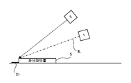
- FIG. 2 is a side view showing an example of a light source and a camera that capture an identification card.
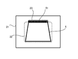
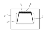
- FIG. 3 is a plan view showing an example of a certificate image.
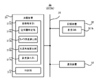
- FIG. 4 is a block diagram showing the configuration of the determination server of the first embodiment.
- FIG. 5 is a flowchart showing the flow of the certificate determination operation performed by the determination server of the first embodiment.
- FIG. 6 is a side view showing a fake ID card illuminated by a light source.
- FIG. 7 is a side view showing a genuine ID card illuminated by a light source.
- FIG. 8 is a block diagram showing the configuration of the determination server of the second embodiment.
- FIG. 1 is a block diagram showing an overall configuration of the certificate determination system of the first embodiment.
- FIG. 2 is a side view showing an example of a light source and a camera that capture an identification card.
- FIG. 3 is a plan view showing an
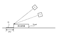
- FIG. 9 is a side view showing a camera angle and a light source angle.
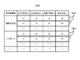
- FIG. 10 is a data structure diagram showing an example of the data structure of the shadow length DB.
- FIG. 11 is a flowchart showing the flow of the certificate determination operation performed by the determination server of the second embodiment.
- FIG. 12 is a plan view showing a certificate image generated under a situation where the camera angle is relatively large.
- FIG. 13 is a plan view showing a certificate image generated under a situation where the camera angle is relatively small.
- FIG. 14 is a side view showing the length of the shadow of a real ID card.
- FIG. 15 is a side view showing the length of the shadow of the fake ID card.
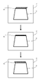
- FIG. 16 is a plan view showing how the direction in which the shadow extends changes.
- FIG. 17 is a data structure diagram showing an example of the data structure of the shadow length DB in the first modification.
- FIG. 18 is a block diagram showing a configuration of the determination server according to the third embodiment.
- Certificate determination system SYS of the first embodiment First, the certificate determination system SYS of the first embodiment will be described. In the following description, the certificate determination system SYS of the first embodiment will be referred to as "certificate determination system SYSA”.
- FIG. 1 is a block diagram showing a configuration of the certificate determination system SYSA of the first embodiment.
- the certificate determination system SYSa includes a light source 1, a camera 2 which is a specific example of an “imaging device”, and a determination server 3 which is a specific example of a “certificate determination device”. .. At least one of the light source 1 and the camera 2 can communicate with the determination server 3 via the communication network (or an arbitrary control line) 4.
- the communication network 4 may include a wired communication network or may include a wireless communication network.
- the light source 1 and the camera 2 are used to image the user's identification card 5 (see FIG. 2).
- the identification card 5 may mean a physical document that can be used to illuminate the user's identity (in other words, identity or identity).
- the identification card 5 at least one of a driver's license, a passport (passport), a health insurance card, an individual number card and an ID card can be mentioned.
- FIG. 2 shows an example of the light source 1 and the camera 2 that capture the identification card 5.
- the light source 1 illuminates the identification card 5 with the illumination light IL.
- the camera 2 takes an image of the identification card 5 illuminated by the illumination light IL from the light source 1.
- the camera 2 generates an image (hereinafter, appropriately referred to as “certificate image 21”) in which the identification card 5 is reflected.
- the camera 2 transmits the generated certificate image 21 to the determination server 3 via the communication network 4.
- the positional relationship between the light source 1 and the camera 2 is fixed. That is, it is preferable that the positional relationship between the light source 1 and the camera 2 does not change.
- the positional relationship between the light source 1 and the camera 2 is preferably information known to the determination server 3.
- a single device may include the light source 1 and the camera 2. That is, the light source and the camera included in the single device may be used as the light source 1 and the camera 2.
- the light source and camera provided in the smartphone or tablet terminal may be used as the light source 1 and the camera 2.
- the positional relationship between the light source 1 and the camera 2 does not have to be fixed. That is, the positional relationship between the light source 1 and the camera 2 may change. Even in this case, it is preferable that the positional relationship between the light source 1 and the camera 2 is information known to the determination server 3. That is, when the positional relationship between the light source 1 and the camera 2 changes, it is preferable that the determination server 3 can specify the positional relationship between the light source 1 and the camera 2 after the change.
- the determination server 3 performs a certificate determination operation for determining whether or not the identification card 5 reflected in the certificate image 21 is genuine based on the certificate image 21. Specifically, the determination server 3 generates the certificate image 21 by imaging the real identification card 5 (hereinafter, appropriately referred to as "identification card 5_real") based on the certificate image 21. It is determined whether the image is a fake image or an image generated by photographing a fake ID card 5 (hereinafter, appropriately referred to as "identification card 5_fake").
- the genuine ID card 5_real in the first embodiment may mean the ID card 5 itself (in other words, the original ID card 5).
- the fake ID card 5_fake in the first embodiment may mean something that imitates the ID card 5 although it is not the ID card 5 itself.
- the ID card 5_fake there is at least one of a display on which a document on which the ID card 5_real is copied and an image in which the ID card 5_real is reflected are displayed.
- the determination server 3 generates shadow information regarding the shadow 51 of the identification card 5 reflected in the certificate image 21, and reflects the shadow information in the certificate image 21 based on the generated shadow information. It is determined whether or not the existing identification card 5 is genuine. Specifically, as shown in FIG. 2 described above, when the light source 1 illuminates the ID card 5_real with the illumination light IL, a shadow 51 of the ID card 5_real is usually generated. As a result, as shown in FIG. 3, which is an example of the certificate image 21, the shadow 51 of the identification card 5_real is also reflected in the certificate image 21 in which the identification card 5_real is reflected. On the other hand, the ID card 5_fake generally has a different thickness than the ID card 5_real.
- the determination server 3 can determine whether or not the identification card 5 reflected in the certificate image 21 is genuine based on the shadow information.
- FIG. 4 shows an example of the configuration of the determination server 3 that performs such a certificate determination operation.
- the determination server 3 includes an arithmetic unit 31, a storage device 32, and a communication device 33.
- the arithmetic unit 31, the storage device 32, and the communication device 33 are connected via the data bus 34.
- the arithmetic unit 31 includes, for example, a CPU (Central Processing Unit).
- the arithmetic unit 31 reads a computer program.
- the arithmetic unit 31 may read the computer program stored in the storage device 32.
- the arithmetic unit 31 may read a computer program stored in a recording medium that is readable by a computer and is not temporary by using a recording medium reading device (not shown).
- the arithmetic unit 31 may acquire a computer program from a device (not shown) arranged outside the determination server 3 via the communication device 33 (that is, it may be downloaded or read).
- the arithmetic unit 31 executes the read computer program.
- a logical functional block for executing an operation to be performed by the determination server 3 (for example, the above-mentioned certificate determination operation) is realized in the arithmetic unit 31. That is, the arithmetic unit 31 can function as a controller for realizing a logical functional block for executing the operation to be performed by the determination server 3.
- FIG. 4 shows an example of a logical functional block realized in the arithmetic unit 31 to execute the certificate determination operation.
- an image analysis unit 311 and a determination unit 312, which is a specific example of the "determination means” are realized in the arithmetic unit 31.
- the shadow detection unit 313, which is a specific example of the "generation means” is realized as a logical functional block. The operations of the image analysis unit 311 and the determination unit 312 will be described in detail later with reference to FIG. 5 and the like.
- the storage device 32 can store desired data.
- the storage device 32 may temporarily store the computer program executed by the arithmetic unit 31.
- the storage device 32 may temporarily store data temporarily used by the arithmetic unit 31 while the arithmetic unit 31 is executing a computer program.
- the storage device 32 may store data stored by the determination server 3 for a long period of time.
- the storage device 32 may include at least one of a RAM (Random Access Memory), a ROM (Read Only Memory), a hard disk device, a magneto-optical disk device, an SSD (Solid State Drive), and a disk array device. good.
- the communication device 33 can communicate with at least one of the light source 1 and the camera 2 via the communication network 4.
- the communication device 33 may receive the certificate image 21 transmitted from the camera 2 via the communication network 4.
- FIG. 5 is a flowchart showing the flow of the certificate determination operation performed by the determination server 3 of the first embodiment.
- the image analysis unit 311 uses the communication device 33 to acquire the certificate image 21 transmitted from the camera 2 via the communication network 4 (step S11).
- the shadow detection unit 313 of the image analysis unit 311 detects the shadow 51 of the identification card 5 reflected in the certificate image 21 based on the certificate image 21 acquired in step S11 (step S12). Specifically, the shadow detection unit 313 analyzes the certificate image 21 to capture an image area (hereinafter referred to as “certificate area 22”) in which the identification card 5 is reflected in the certificate image 21. 3) is specified. After that, the shadow detection unit 313 analyzes the certificate image 21 to extend outward from the certificate area 22 and the shadow 51 of the identification card 5 is reflected in the image area (hereinafter, “shadow area”). It is determined whether or not there is (see FIG. 3) referred to as “23”.
- the shadow detection unit 313 determines that the shadow 51 of the identification card 5 is reflected in the certificate image 21.
- the shadow detection unit 313 determines that the shadow 51 of the identification card 5 is not reflected in the certificate image 21.
- the detection result of the shadow 51 by the shadow detection unit 313 in step S12 is output from the shadow detection unit 313 to the determination unit 312 as shadow information. That is, in the first embodiment, the shadow information including the information regarding the presence / absence of the shadow 51 in the certificate image 21 is output from the shadow detection unit 313 to the determination unit 312.
- the determination unit 312 determines whether or not the identification card 5 reflected in the certificate image 21 is genuine based on the shadow information (step S13). Specifically, as described above, the thickness of the ID card 5_fake is relatively likely to be thinner (especially much thinner) than the thickness of the ID card 5_real. Therefore, as shown in FIG. 6, which is a side view showing the identification card 5_fake illuminated by the light source 1, when the light source 1 illuminates the identification card 5_fake with the illumination light IL, the identification card There is a high possibility that the shadow 51 of 5_fake is hardly generated.
- FIG. 7 which is a side view showing the identification card 5_real illuminated by the light source 1
- the identification card 5_real has a certain thickness.
- the shadow 51 of the identification card 5_real is reflected in the certificate image 21 in which the identification card 5_real is reflected.
- the determination unit 312 determines that the identification card 5 reflected in the certificate image 21 is a fake when the shadow 51 is not reflected in the certificate image 21. May be good. That is, the determination unit 312 may determine that the identification card 5_fake is reflected in the certificate image 21. On the other hand, the determination unit 312 determines that the identification card 5 reflected in the certificate image 21 is genuine when the shadow 51 is reflected in the certificate image 21 based on the shadow information. You may. That is, the determination unit 312 may determine that the identification card 5_real is reflected in the certificate image 21.
- the certificate judgment system SYSA (particularly, judgment server 3) of the first embodiment has an identification card reflected in the certificate image 21. Based on the presence or absence of the shadow 51 of 5, it can be determined whether or not the identification card 5 reflected in the certificate image 21 is genuine. Therefore, as compared with the case where a person visually confirms the certificate image 21 to determine whether or not the identification card 5 reflected in the certificate image 21 is genuine, the certificate determination system SYSSa (In particular, the determination server 3) can determine whether or not the identification card 5 reflected in the certificate image 21 is genuine at a relatively low cost.
- Certificate determination system SYS of the second embodiment (2) Certificate determination system SYS of the second embodiment Subsequently, the certificate determination system SYS of the second embodiment will be described. In the following description, the certificate determination system SYS of the second embodiment will be referred to as "certificate determination system SYSb".
- the certificate judgment system SYSb of the second embodiment replaces the judgment server 3 as compared with the certificate judgment system SYSa of the first embodiment. It differs in that it includes a determination server 3b. Other features of the certificate determination system SYSb may be the same as other features of the certificate determination system SYSa.
- the judgment server 3b Similar to the judgment server 3, the judgment server 3b generates shadow information regarding the shadow 51 of the identification card 5 reflected in the certificate image 21, and reflects the shadow information on the certificate image 21 based on the generated shadow information. Performs a certificate determination operation for determining whether or not the existing identification card 5 is genuine. However, the determination server 3b generates the shadow information including the information regarding the presence / absence of the shadow 51 of the identification card 5 in that the determination server 3b generates the shadow information including the information regarding the length L of the shadow 51 of the identification card 5. Different from server 3. Other features of the determination server 3b may be the same as other features of the determination server 3. Therefore, in the following, the determination server 3b of the second embodiment will be described with reference to FIG. 8, focusing on the differences between the determination server 3b and the determination server 3.
- FIG. 8 is a block diagram showing the configuration of the determination server 3b of the second embodiment.
- the determination server 3b is different from the determination server 3 in that the image analysis unit 311b is realized in the arithmetic unit 31 instead of the image analysis unit 311. Further, the determination server 3b is different from the determination server 3 in that the storage device 32 stores the shadow length DB321b, which is a specific example of the “estimated length data”. Other configurations of the determination server 3b may be the same as other configurations of the determination server 3.
- the image analysis unit 311b replaces the shadow detection unit 313 with a certificate identification unit 314b, a camera angle calculation unit 315b which is a specific example of the "calculation means", and a "calculation means”.
- the light source angle calculation unit 316b which is a specific example of the above
- the shadow length calculation unit 317b which is a specific example of the “generation means”.
- the certificate specifying unit 314b identifies the type of the identification card 5 reflected in the certificate image 21 based on the certificate image 21.
- the camera angle calculation unit 315b calculates the angle of the camera 2 with respect to the identification card 5 (hereinafter referred to as “camera angle ⁇ c”) based on the certificate image 21.
- the light source angle calculation unit 316b calculates the angle of the light source 1 with respect to the identification card 5 (hereinafter referred to as “light source angle ⁇ o”) based on the certificate image 21.
- the shadow length calculation unit 317b calculates the length L of the shadow 51 of the identification card 5 reflected in the certificate image 21 based on the certificate image 21.
- the determination unit 312 is a certificate image based on the camera angle ⁇ c calculated by the camera angle calculation unit 315b, the light source angle ⁇ o calculated by the light source angle calculation unit 316b, and the length L of the shadow 51 calculated by the shadow length calculation unit 317b. It is determined whether or not the identification card 5 reflected in the 21 is genuine.
- the camera angle ⁇ c is a parameter (in other words, an index) that represents the relative positional relationship between the camera 2 and the ID card 5.
- An example of the camera angle ⁇ c is shown in FIG.
- the camera angle ⁇ c may indicate, for example, the angle formed by the camera axis AC extending from the camera 2 and the surface of the ID card 5.
- the camera angle ⁇ c is, for example, the angle formed in the vertical direction between the camera axis AC and the axis along the surface of the ID card 5 (for example, the axis along either the short side or the long side of the ID card 5). (See FIG.
- the camera axis AC may be an axis extending from the camera 2 toward a predetermined position of the ID card 5 (in the example shown in FIG. 9, the upper end of the ID card 5).
- the camera axis AC may be an axis along the optical axis of the optical system (for example, a lens) included in the camera 2.
- the light source angle ⁇ o is a parameter (in other words, an index) that represents the relative positional relationship between the light source 1 and the ID card 5.
- An example of the light source angle ⁇ o is shown in FIG.
- the light source angle ⁇ o may indicate, for example, the angle formed by the light source axis OC extending from the light source 1 and the surface of the ID card 5.
- the light source angle ⁇ o is, for example, the angle formed in the vertical direction between the light source axis OC and the axis along the surface of the ID card 5 (for example, the axis along either the short side or the long side of the ID card 5). (See FIG.
- the light source axis OC may be an axis extending from the light source 1 toward a predetermined position of the ID card 5 (in the example shown in FIG. 9, the upper end of the ID card 5).
- the light source axis OC may be an axis along the optical axis of the optical system (for example, a lens) included in the light source 1.
- the light source axis OC may be an axis along the traveling direction of the illumination light IL emitted from the light source 1.
- the shadow length DB321b is a database referred to by the determination unit 312 in order to determine whether or not the identification card 5 reflected in the certificate image 21 is genuine. Specifically, the shadow length DB321b is presumed to be reflected in the certificate image 21 from the camera angle ⁇ c calculated by the camera angle calculation unit 315b and the light source angle ⁇ o calculated by the light source angle calculation unit 316b. It is used to estimate the length L of the shadow 51 of the book 5. Therefore, the shadow length DB321b is a database showing the relationship between the camera angle ⁇ c and the light source angle ⁇ o and the length L of the shadow 51. An example of the data structure of the shadow length DB321b is shown in FIG. As shown in FIG.
- the shadow length DB321b includes a plurality of record data 322b.
- the camera 2 captured the real identification card 5_real illuminated by the light source 1 under the condition that the camera angle ⁇ c is a predetermined first angle and the light source angle ⁇ o is a predetermined second angle.
- the length L of the shadow 51 of the identification certificate 5_real which is presumed to be reflected in the certificate image 21, is associated with the camera angle ⁇ c and the light source angle ⁇ o. That is, in each record data 322b, the identification card 5_real illuminated by the light source 1 arranged so that the light source angle ⁇ o becomes a predetermined second angle is arranged so that the camera angle ⁇ c becomes a predetermined second angle.
- the theoretical (in other words, design) length L of the shadow 51 of the identification card 5_real, which is presumed to be reflected in the certificate image 21, assuming that the camera 2 has taken an image, is the camera. It is associated with the angle ⁇ c and the light source angle ⁇ o.
- the shadow length DB321b is, for example, (i) an identification 5_real illuminated by the light source 1 arranged so that the light source angle ⁇ o is the angle a2, and the camera angle ⁇ c is the angle a1.
- Record data 322b indicating that the length L of the shadow 51 of the identification card 5_real, which is presumed to be reflected in the certificate image 21, is a4, assuming that the camera 2 arranged in the above manner captures the image.
- the length L of the shadow 51 of the ID card 5_real may change depending on the distance (that is, the distance) D between the light source 1 and the camera 2 in addition to the light source angle ⁇ o and the camera angle ⁇ c. .. Therefore, in each record data 322b, the camera angle ⁇ c is a predetermined first angle, the light source angle ⁇ o is a predetermined second angle, and the distance D between the light source 1 and the camera 2 is a predetermined distance.
- the length of the shadow 51 of the identification card 5_real that is presumed to be reflected in the certificate image 21 if the camera 2 takes an image of the real identification card 5_real illuminated by the light source 1 under the circumstances.
- the L may be associated with the camera angle ⁇ c, the light source angle ⁇ o, and the distance D between the light source 1 and the camera 2.
- the "distance" in the second embodiment may include at least one of a distance along the X axis, a distance along the Y axis, and a distance along the Z axis in the XYZ coordinate systems orthogonal to each other.
- the shadow length DB321b is, for example, (i) an identification 5_real illuminated by the light source 1 arranged so that the light source angle ⁇ o is the angle a2, and the camera angle ⁇ c is the angle a1.
- the length L of the shadow 51 of the identification card 5_real estimated to be reflected in the certificate image 21 is a4.
- the record data 322b indicating that there is, and (ii) the identification certificate 5_real illuminated by the light source 1 arranged so that the light source angle ⁇ o is the angle b2, the camera angle ⁇ c is the angle b1 and the distance b3 from the light source 1.
- a record indicating that the length L of the shadow 51 of the identification card 5_real, which is presumed to be reflected in the certificate image 21, is b4, assuming that the camera 2 is arranged so as to be separated from the image. Includes data 322b.
- the length L of the shadow 51 of the ID card 5_real may change depending on the thickness of the ID card 5_real in addition to the light source angle ⁇ o and the camera angle ⁇ c.
- the thickness of the ID card 5_real depends on the type of the ID card 5_real. For example, the thickness of a driver's license, which is an example of ID card 5_real, is different from the thickness of a passport, which is an example of ID card 5_real. Therefore, the shadow length DB321b may include record data 322b for each type of identification card 5_real.
- the shadow length DB321b is the length of the record data 322b indicating the length of the shadow 51 of the first type of identification card 5_real and the length of the shadow 51 of the second type of identification card 5_real different from the first type.
- the record data 322b indicating the above may be included.
- the shadow length DB321b is the record data 322b indicating the length L of the shadow 51 of the driver's license, which is an example of the identification card 5_real, and the shadow 51 of the passport, which is an example of the identification card 5_real. It includes record data 322b indicating a length L.
- the determination unit 312 is reflected in the certificate image 21 based on such a shadow length DB321b, a camera angle ⁇ c calculated by the camera angle calculation unit 315b, and a light source angle ⁇ o calculated by the light source angle calculation unit 316b.
- the length L of the shadow 51 of the estimated identification card 5 (that is, the estimated value of the length L of the shadow 51) is estimated. That is, the determination unit 312 assumes that the real identification card 5_real is reflected in the certificate image 21, and the length L of the shadow 51 reflected in the certificate image 21 (that is, the length L of the shadow 51). Estimated value).
- the determination unit 312 determines the length L of the shadow 51 estimated by the determination unit 312 (that is, the estimated value of the length L of the shadow 51) and the length L of the shadow 51 calculated by the shadow length calculation unit 317b (that is, that is). , The calculated value of the length L of the shadow 51), and it is determined whether or not the identification card 5 reflected in the certificate image 21 is genuine.
- FIG. 11 is a flowchart showing the flow of the certificate determination operation performed by the determination server 3 of the second embodiment.
- the image analysis unit 311 uses the communication device 33 to acquire the certificate image 21 transmitted from the camera 2 via the communication network 4 (step S21).
- the certificate identification unit 314b of the image analysis unit 311 specifies the type of the identification card 5 reflected in the certificate image 21 based on the certificate image 21 acquired in step S11 (step S22). That is, the certificate specifying unit 314b analyzes the certificate image 21 to specify the type of the identification card 5 reflected in the certificate image 21 (step S22). For example, the certificate identification unit 314b identifies the type of the ID card 5 based on the characteristics of the ID card 5 (for example, at least one of size, color, and shape) reflected in the certificate image 21. You may. For example, the certificate specifying unit 314b may specify the type of the ID card 5 by performing pattern matching processing on the certificate image 21 using a template conforming to the format of the ID card 5. ..
- the certificate specifying unit 314b identifies the image area (that is, the certificate area 22) in which the identification card 5 is reflected in the certificate image 21 as in the shadow detection unit 313 of the first embodiment. You may.
- the image analysis unit 311 does not have to specify the type of the identification card 5. In this case, the image analysis unit 311 may not include the certificate identification unit 314b.
- the shadow length calculation unit 317b calculates the length L of the shadow 51 of the identification card 5 reflected in the certificate image 21 based on the certificate image 21 acquired in step S11 (step S23).
- the size of the identification card 5 is an eigenvalue depending on the type of the identification card 5. Therefore, the size of the identification card 5 can be used as a reference length when calculating the length L of the shadow 51. Therefore, first, the shadow length calculation unit 317b determines the size of the identification card 5 (for example, the length of at least one of the long side and the short side) based on the type of the identification card 5 specified by the certificate identification unit 314b. ).
- the size of the identification card 5 is equivalent to the size of the certificate area 22 in the certificate image 21.
- the shadow length calculation unit 317b detects an image region (that is, a shadow region 23) in which a shadow extending outward from the certificate region 22 is reflected, similarly to the shadow detection unit 313 described in the first embodiment. do. After that, the shadow length calculation unit 317b calculates the size of the detected shadow area 23 based on the size of the certificate area 22.
- the size of the shadow area 23 is, for example, from one end of the shadow area 23 adjacent to the certificate area 22 to the other end of the shadow area 23 away from the certificate area 22 along the traveling direction of the illumination light IL. It may be the distance to the part.
- the calculated size of the shadow region 23 is used as the length L of the shadow 51.
- the calculation result of the length L of the shadow 51 by the shadow length calculation unit 317b in step S23 is output from the shadow length calculation unit 317b to the determination unit 312 as shadow information. That is, in the second embodiment, the shadow information including the information regarding the length L of the shadow 51 in the certificate image 21 is output from the shadow length calculation unit 317b to the determination unit 312.
- the camera angle calculation unit 315b determines the angle of the camera 2 with respect to the identification card 5 (that is, the camera angle ⁇ c) based on the certificate image 21 acquired in step S11. ) Is calculated (step S24). Specifically, when the camera angle ⁇ c changes, the ratio of the lengths of the two intersecting sides (for example, the long side and the short side) of the identification card 5 reflected in the certificate image 21 changes.
- FIG. 12 shows a certificate image 21 generated under a situation where the camera angle ⁇ c formed by the camera axis AC and the surface of the ID card 5 is relatively large
- FIG. 13 shows the camera axis AC.
- the certificate image 21 generated under the condition that the camera angle ⁇ c formed by the surface of the identification card 5 is relatively small is shown.
- the smaller the camera angle ⁇ c the shorter the short side of the ID card 5 (the side extending in the left-right direction in the examples shown in FIGS. 12 and 13) of the ID card 5.
- the ratio of the sides extending in the vertical direction becomes small. Therefore, the camera angle calculation unit 315b may calculate the camera angle ⁇ c based on the ratio of the lengths of the two intersecting sides of the ID card 5.
- the camera angle ⁇ c calculated here corresponds to the camera angle ⁇ c at the time when the camera 2 captures the identification card 5.
- the camera angle ⁇ c calculated in step S24 is output from the camera angle calculation unit 315b to the determination unit 312.
- the light source angle calculation unit 316b calculates the angle of the light source 1 with respect to the identification card 5 (that is, the light source angle ⁇ o) based on the camera angle ⁇ c specified in step S24 (step S25). Specifically, when the positional relationship between the light source 1 and the camera 2 is fixed as described above, when the camera angle ⁇ c is determined, the light source angle ⁇ o is also uniquely determined. Alternatively, even if the positional relationship between the light source 1 and the camera 2 is not fixed, the camera angle ⁇ c is determined when the positional relationship between the light source 1 and the camera 2 is known information to the determination server 3. And the light source angle ⁇ o is also uniquely determined.
- the light source angle calculation unit 316b can calculate the light source angle ⁇ o based on the camera angle ⁇ c (further, based on the positional relationship between the light source 1 and the camera 2 if necessary).
- the light source angle ⁇ o calculated here corresponds to the light source angle ⁇ o at the time when the camera 2 takes an image of the identification card 5.
- the light source angle ⁇ o calculated in step S25 is output from the light source angle calculation unit 316b to the determination unit 312.
- the determination unit 312 After that, it is estimated that the determination unit 312 will be reflected in the certificate image 21 based on the camera angle ⁇ c calculated in step S24, the light source angle ⁇ o calculated in step S25, and the shadow length DB321b.
- the length L of the shadow 51 of the identification card 5 is estimated (step S26). That is, the determination unit 312 assumes that the real identification card 5_real is reflected in the certificate image 21, and the length L of the shadow 51 reflected in the certificate image 21 (that is, the length L of the shadow 51). Estimated value).
- the determination unit 312 uses the real identification card 5_real illuminated by the light source 1 arranged at the position based on the light source angle ⁇ o calculated in step S25 based on the camera angle ⁇ c calculated in step S24.
- the theoretical (in other words, design) length of the shadow 51 of the ID card 5_real which is presumed to be reflected in the certificate image 21, assuming that the camera 2 located at the position has taken an image.
- Estimate L In order to estimate the length L of the shadow 51, for example, the determination unit 312 obtains record data 322b corresponding to the camera angle ⁇ c calculated in step S24 and the light source angle ⁇ o calculated in step S25 from the shadow length DB 321b. Extract. After that, the determination unit 312 uses the length L of the shadow 51 indicated by the extracted record data 322b as an estimated value of the length L of the shadow 51.
- the determination unit 312 specifies the distance D between the light source 1 and the camera 2.
- the record data 322b corresponding to the specified distance D may be extracted from the shadow length DB321b.
- the distance D between the light source 1 and the camera 2 is a fixed value when the positional relationship between the light source 1 and the camera 2 is fixed.
- the distance D between the light source 1 and the camera 2 is a variable value.
- the determination server 3 may specify the distance D between the light source 1 and the camera 2. can.
- the determination unit 312 is reflected on the certificate image 21 based on the calculated value of the length L of the shadow 51 calculated in step S23 and the estimated value of the length L of the shadow 51 estimated in step S26. It is determined whether or not the embedded identification card 5 is genuine (step S27). Specifically, as shown in FIG. 14, when the identification card 5 reflected in the certificate image 21 is genuine (that is, the identification card 5_real), the length L of the shadow 51 The calculated value L1 is substantially the same as the estimated value of the length L of the shadow 51 (that is, the theoretical length L). On the other hand, as shown in FIG.
- the calculated value L2 of the length L of the shadow 51 Is a value different from the estimated value of the length L of the shadow 51 (that is, the theoretical length L). This is because when the ID card 5 reflected in the certificate image 21 is not genuine, the calculated value of the length L of the shadow 51 is the shadow 51 of the ID card 5_fake whose thickness is different from that of the ID card 5_real. This is because it indicates the length L of.
- the calculated value L2 of the length L of the shadow 51 of the ID card 5_fake corresponds to the theoretical value of the length L1 of the shadow 51 of the ID card 5_real (or the length L1 of the shadow 51 of the ID card 5_real).
- Estimated value of the length L of the shadow 51 Therefore, the determination unit 312 compares the calculated value of the length L of the shadow 51 calculated in step S23 with the estimated value of the length L of the shadow 51 estimated in step S26 to obtain the certificate image 21. It is possible to determine whether or not the identification card 5 reflected in the image is genuine.
- the difference between the calculated value of the length L of the shadow 51 and the estimated value of the length L of the shadow 51 is larger than the predetermined first allowable amount (that is, the calculation of the length L of the shadow 51). If the value is significantly different from the estimated value of the length L of the shadow 51), it may be determined that the identification card 5 reflected in the certificate image 21 is not genuine.
- the difference between the calculated value of the length L of the shadow 51 and the estimated value of the length L of the shadow 51 is smaller than the predetermined second allowable amount equal to or less than the first allowable amount (that is, the shadow 51). If the calculated value of the length L of the shadow 51 does not differ significantly from or is approximately the same as the estimated value of the length L of the shadow 51), it is considered that the identification card 5 reflected in the certificate image 21 is genuine. You may judge.
- the first and second permissible amounts are the state in which the identification card 5 reflected in the certificate image 21 is genuine and the state in which the identification card 5 reflected in the certificate image 21 is not genuine. , It may be set to an appropriate value that can be distinguished from the length L of the shadow 51 of the identification card 5 reflected in the certificate image 21. Such first and second tolerances may be set experimentally or by simulation. The first allowable amount may be the same as or different from the second allowable amount.
- the certificate judgment system SYSb (particularly, judgment server 3b) of the second embodiment has an identification card reflected in the certificate image 21. Based on the length L of the shadow 51 of 5, it can be determined whether or not the identification card 5 reflected in the certificate image 21 is genuine. Therefore, the certificate determination system SYSb is compared with the case where a person visually confirms the certificate image 21 to determine whether or not the identification card 5 reflected in the certificate image 21 is genuine. (In particular, the determination server 3b) can determine whether or not the identification card 5 reflected in the certificate image 21 is genuine at a relatively low cost.
- the certificate determination system SYSb (particularly, the determination server 3b) can determine with higher accuracy whether or not the identification card 5 reflected in the certificate image 21 is genuine.
- the determination server 3b is a shadow containing information about a change in length L (typically a time-series change) of the shadow 51 of the ID card 5. Information may be generated. Specifically, the determination server 3b acquires a plurality of certificate images 21 transmitted from the camera 2. The plurality of certificate images 21 are generated by repeating the operation of the camera 2 taking an image of the identification card 5 and the operation of changing the positional relationship between the identification card 5 and at least one of the light source 1 and the camera 2. To. That is, in the first modification, the camera 2 takes an image of the identification card 5 each time the positional relationship between the identification card 5 and at least one of the light source 1 and the camera 2 is changed.
- the plurality of certificate images 21 may be a plurality of images constituting the moving image.
- the shadow length calculation unit 317b of the determination server 3b calculates the length L of the shadow 51 of the identification card 5 reflected in each of the plurality of certificate images 21.
- the shadow length calculation unit 317b can calculate the time-series change of the length L of the shadow 51.
- the calculation result of the length L of the shadow 51 by the shadow length calculation unit 317b is output from the shadow length calculation unit 317b to the determination unit 312 as shadow information.
- the camera angle calculation unit 315b calculates the camera angle ⁇ c based on each of the plurality of certificate images 21. As a result, the camera angle calculation unit 315b calculates the time-series change of the camera angle ⁇ c. Similarly, the light source angle calculation unit 316b calculates the time-series change of the light source angle ⁇ o based on the time-series change of the camera angle ⁇ c.
- the determination unit 312 presumes that the identification card 5 will be reflected in the certificate image 21 based on the time-series change of the camera angle ⁇ c, the time-series change of the light source angle ⁇ o, and the shadow length DB321b. Estimate the time-series change of the length L of the shadow 51 of. That is, the determination unit 312 changes the length L of the shadow 51 reflected on the certificate image 21 over time (that is, the shadow 51) on the assumption that the real identification card 5_real is reflected on the certificate image 21. (Estimated value of time-series change of length L) is estimated.
- the determination unit 312 uses the calculated value of the time-series change of the length L of the shadow 51 calculated by the shadow length calculation unit 317b and the estimated value of the time-series change of the length L of the shadow 51 estimated by the determination unit 312. By comparing, it is determined whether or not the identification card 5 reflected in the certificate image 21 is genuine. That is, in the first modification, the determination unit 312 has a change pattern of the length L of the shadow 51 actually reflected in the certificate image 21 (hereinafter referred to as “actual change pattern”) and the certificate image 21.
- the identification card 5 reflected in the certificate image 21 can be obtained. Determine if it is genuine. For example, when the similarity between the actual change pattern of the length L of the shadow 51 and the estimated change pattern of the length L of the shadow 51 is higher than the first threshold value, the determination unit 312 is reflected in the certificate image 21. It may be determined that the identification card 5 is genuine. For example, the determination unit 312 obtains a certificate when the similarity between the actual change pattern of the length L of the shadow 51 and the estimated change pattern of the length L of the shadow 51 is lower than the second threshold value equal to or less than the first threshold value. It may be determined that the identification card 5 reflected in the image 21 is not genuine.
- the first and second thresholds are a state in which the identification card 5 reflected in the certificate image 21 is genuine and a state in which the identification card 5 reflected in the certificate image 21 is not genuine. It may be set to an appropriate value that can be distinguished from the change pattern (that is, time-series change) of the length L of the shadow 51 of the identification card 5 reflected in the certificate image 21. Such first and second thresholds may be set experimentally or by simulation. The first threshold may be the same as or different from the second threshold.
- the determination server 3b performs the certificate determination operation by using the time-series change of the length L of the shadow 51.
- the determination server 3b may perform the certificate determination operation by using an arbitrary time-series change of the shadow 51. That is, the determination server 3b may perform the certificate determination operation by using the time-series change of an arbitrary parameter representing the state of the shadow 51. For example, if the positional relationship between the ID card 5 and at least one of the light source 1 and the camera 2 is changed, the direction in which the shadow 51 extends from the ID card 5 (that is, the direction of the shadow 51) may change. For example, in FIG.
- the direction in which the shadow 51 extends is the first direction extending from the ID card 5 toward the upper right, the second direction extending upward from the ID card 5, and the direction extending from the ID card 5 toward the upper left. It shows how it changes in order in the extending third direction. Therefore, the determination server 3b may perform the certificate determination operation by using the time-series change in the extending direction of the shadow 51. For example, the shadow length calculation unit 317b of the determination server 3b may calculate the direction in which the shadow 51 of the identification card 5 reflected in each of the plurality of certificate images 21 extends. As a result, the shadow length calculation unit 317b can calculate the time-series change in the extending direction of the shadow 51.
- the determination unit 312 is presumed to be reflected in the certificate image 21 based on the time-series change of the camera angle ⁇ c, the time-series change of the light source angle ⁇ o, and the shadow length DB321b. Estimate the time-series change in the extending direction of the shadow 51 of 5. However, in this case, each record data 322b of the shadow length DB321b is presumed to be reflected in the certificate image 21 as shown in FIG. 17 showing another example of the shadow length DB321b. It is preferable that the direction in which the shadow 51 extends is associated with the camera angle ⁇ c and the light source angle ⁇ o.
- the determination unit 312 compares the calculated value of the time-series change in the extension direction of the shadow 51 calculated by the shadow length calculation unit 317b with the estimated value of the time-series change in the extension direction of the shadow 51 estimated by the determination unit 312. Therefore, it may be determined whether or not the identification card 5 reflected in the certificate image 21 is genuine. For example, when the similarity between the actual change pattern in the extending direction of the shadow 51 and the estimated change pattern in the extending direction of the shadow 51 is higher than the third threshold value, the determination unit 312 is reflected in the certificate image 21. It may be determined that the identification card 5 is genuine.
- the determination unit 312 determines that the similarity between the actual change pattern in the extending direction of the shadow 51 and the estimated change pattern in the extending direction of the shadow 51 is lower than the fourth threshold value equal to or less than the third threshold value, the certificate image 21 It may be determined that the identification card 5 reflected in the image is not genuine.
- the third and fourth thresholds are a state in which the identification card 5 reflected in the certificate image 21 is genuine and a state in which the identification card 5 reflected in the certificate image 21 is not genuine. It may be set to an appropriate value that can be distinguished from the change pattern in the extending direction of the shadow 51 of the identification card 5 reflected in the certificate image 21.
- Such third and fourth thresholds may be set experimentally or by simulation.
- the third threshold may be the same as or different from the fourth threshold.
- step S26 of FIG. 11 the determination unit 312 uses the shadow 51 of the identification card 5 based on the camera angle ⁇ c, the light source angle ⁇ o, and the shadow length DB321b. The length L of is estimated. After that, the determination unit 312 determines the calculated value of the shadow 51 length L calculated by the shadow length calculation unit 317b in step S23 and the shadow 51 length L estimated by the determination unit 312 in step S26 in step S27 of FIG. By comparing with the estimated value of, it is determined whether or not the identification card 5 reflected in the certificate image 21 is genuine.
- the determination unit 312 has a shadow having a length L calculated by the shadow length calculation unit 317b based on the length L of the shadow 51 calculated by the shadow length calculation unit 317b and the shadow length DB 321b in step S23. Assuming that 51 is reflected in the certificate image 21, the light source angle ⁇ o estimated that the light source 1 will form the identification card 5_real may be estimated. That is, the determination unit 312 may estimate the estimated value of the light source angle ⁇ o.
- step S27 the determination unit 312 appears on the certificate image 21 based on the actual calculated value of the light source angle ⁇ o calculated in step S25 and the estimated value of the light source angle ⁇ o estimated in step S26. It may be determined whether or not the embedded identification card 5 is genuine.
- the estimated value of the light source angle ⁇ o estimated in step S26 is The value is almost the same as the actual calculated value of the light source angle ⁇ o.
- the estimated value of the light source angle ⁇ o estimated in step S26 is the light source angle ⁇ o. It will be different from the actual calculated value of.
- the determination unit 312 compares the calculated value of the light source angle ⁇ o calculated in step S24 with the estimated value of the light source angle ⁇ o estimated in step S26, and the identification unit is reflected in the certificate image 21. It can be determined whether the certificate 5 is genuine or not.
- the actual light source angle ⁇ o calculated in step S24 forms an ideal (in other words, design) light source angle ⁇ o having the shadow 51 having the length L calculated in step S23.
- the difference between the calculated value of the light source angle ⁇ o and the estimated value of the light source angle ⁇ o is larger than the predetermined third allowable amount (that is, the calculated value of the light source angle ⁇ o is the estimated value of the light source angle ⁇ o).
- the identification card 5 reflected in the certificate image 21 is not genuine.
- the difference between the calculated value of the light source angle ⁇ o and the estimated value of the light source angle ⁇ o is smaller than the predetermined fourth allowable amount equal to or less than the third allowable amount (that is, the calculated value of the light source angle ⁇ o is small. If it does not differ significantly from or is substantially the same as the estimated value of the light source angle ⁇ o), it may be determined that the identification card 5 reflected in the certificate image 21 is genuine.
- the third and fourth permissible amounts are the state where the identification card 5 reflected in the certificate image 21 is genuine and the state where the identification card 5 reflected in the certificate image 21 is not genuine. , It may be set to an appropriate value that can be distinguished from the light source angle ⁇ o. Such third and fourth permissible amounts may be set experimentally or by simulation. The third allowable amount may be the same as or different from the fourth allowable amount.
- the camera angle calculation unit 315b does not have to calculate the camera angle ⁇ c.
- the image analysis unit 311 may not include the camera angle calculation unit 315b.
- the determination server 3b performs a certificate determination operation using the camera angle ⁇ c.
- the camera angle ⁇ c is a specific example of a parameter representing the relative positional relationship between the camera 2 and the ID card 5. Therefore, the determination server 3b performs the certificate determination operation by using an arbitrary parameter representing the relative positional relationship between the camera 2 and the ID card 5 in addition to or instead of the camera angle ⁇ c. May be good.
- arbitrary parameters representing the relative positional relationship between the camera 2 and the ID card 5 the distance from the ID card 5 to the camera 2 and the orientation in which the camera 2 is located with respect to the ID card 5. At least one of them can be mentioned.
- the determination server 3b performs the certificate determination operation using the light source angle ⁇ o.
- the light source angle ⁇ o is a specific example of a parameter representing the relative positional relationship between the light source 1 and the ID card 5. Therefore, the determination server 3b performs the certificate determination operation by using an arbitrary parameter representing the relative positional relationship between the light source 1 and the ID card 5 in addition to or instead of the light source angle ⁇ o. May be good.
- an arbitrary parameter representing the relative positional relationship between the light source 1 and the ID card 5 the distance from the ID card 5 to the light source 1 and the direction in which the light source 1 is located with respect to the ID card 5. At least one of them can be mentioned.
- certificate determination system SYS of the third embodiment will be described.
- the certificate determination system SYS of the third embodiment will be referred to as "certificate determination system SYSc".
- the certificate determination system SYSc of the third embodiment is different from the certificate determination system SYSa of the first embodiment in that the determination server 3c is provided in place of the determination server 3.
- Other features of the certificate determination system SYSc may be the same as other features of the certificate determination system SYS. Therefore, in the following, the determination server 3c of the third embodiment will be described with reference to FIG. 18, focusing on the differences between the determination server 3c and the determination server 3.
- FIG. 18 is a block diagram showing a configuration of the determination server 3c according to the third embodiment.
- the light source control unit 318c which is a specific example of the "control means" is realized in the arithmetic unit 31 as a logical processing block. It differs in that.
- Other configurations of the determination server 3c may be the same as other configurations of the determination server 3.
- the light source control unit 318c can control the light source 1 via the communication network 4.
- the light source control unit 318c may control the characteristics (for example, intensity) of the illumination light IL by controlling the light source 1.
- the light source control unit 318c may control the characteristics of the illumination light IL so that the shadow 51 is appropriately reflected on the certificate image 21 as compared with before controlling the characteristics of the illumination light IL.
- the state in which the shadow 51 is appropriately reflected in the certificate image 21 means, for example, a state in which the shadow 51 is reflected in the certificate image 21 to the extent that the image analysis unit 311 can appropriately detect the shadow 51. You may.
- the state in which the shadow 51 is properly reflected in the certificate image 21 is such that the contrast between the shadow area 23 in which the shadow 51 is reflected and an image area other than the shadow area 23 becomes a certain amount or more. It may mean that the shadow 51 is clearly reflected in the certificate image 21.
- Such a certificate determination system SYSc of the third embodiment enjoys the same effect as the effect that can be enjoyed by the certificate determination system SYSa of the first embodiment described above, and the shadow reflected on the certificate image 21. 51 can be detected appropriately.
- the light source control unit 318c may control the camera 2 via the communication network 4 in addition to or instead of controlling the light source 1.
- the light source control unit 318c may control the optical characteristics (for example, sensitivity) of the camera 2 by controlling the camera 2.
- the light source control unit 318c may control the optical characteristics of the camera 2 so that the shadow 51 is appropriately reflected on the certificate image 21 as compared with before controlling the optical characteristics of the camera 2.
- the certificate determination system SYSc appropriately obtains the shadow 51 reflected in the certificate image 21 while enjoying the same effect as the effect that can be enjoyed by the certificate determination system SYSa of the first embodiment described above. Can be detected.
- the image is generated by the image pickup device taking an image of the identification card illuminated by the illumination light from the light source.
- the shadow information includes information regarding the length of the shadow.
- a calculation means for calculating the positional relationship between the ID card, the light source, and the image pickup device at the time when the ID card is imaged based on the image is further provided.
- the determination means is (I) Based on the estimated length data indicating the length of the shadow that is estimated to be reflected in the image when it is assumed that the identification card is imaged under the condition that the positional relationship is a predetermined relationship.
- the length of the shadow which is estimated to be reflected in the image when it is assumed that the identification card is imaged under the situation where the positional relationship calculated by the calculation means is established, is estimated.
- the determination means is (I) Based on the estimated length data indicating the length of the shadow that is estimated to be reflected in the image when it is assumed that the identification card is imaged under the condition that the positional relationship is a predetermined relationship. The positional relationship established when it is assumed that a shadow of the length indicated by the shadow information is reflected in the image is estimated. (Ii) The certificate determination device according to Appendix 1 to 4, which determines whether or not the identification card is genuine by comparing the estimated positional relationship with the positional relationship calculated by the calculation means. ..
- the identification card is not genuine when the second difference, which is the difference between the estimated positional relationship and the positional relationship calculated by the calculation means, is larger than the third allowable amount.
- the certificate determination device according to Appendix 5, which determines that the identification card is genuine when the second difference is smaller than the fourth allowable amount of the third allowable amount or less.
- the image is generated by the image pickup device taking an image of the identification card illuminated by the illumination light from the light source.
- the generation means is generated by repeating an operation of capturing the identification card by the image pickup apparatus and an operation of changing the positional relationship between the identification card and at least one of the light source and the image pickup device.
- the certificate determination device according to any one of Supplementary note 1 to 6, which generates information on the change of the shadow reflected in the image as the shadow information based on the image of the above.
- Appendix 8 A calculation means for calculating the positional relationship between the ID card, the light source, and the image pickup device at the time when the ID card is imaged based on the image is further provided.
- the determination means is (I) Estimated length data indicating the length of the shadow estimated to be reflected in the image when it is assumed that the identification card is imaged under the situation where the positional relationship is a predetermined relationship, and the calculation. Based on the positional relationship calculated by the means, the change in the shadow between the plurality of images is estimated.
- the certificate determination device for determining whether or not the identification card is genuine by comparing the estimated change in shadow with the change in shadow indicated by the shadow information. ..
- the state of the change of the shadow is the certificate determination device according to Appendix 7 or 8, which includes at least one of the change in the length of the shadow and the change in the direction in which the shadow extends.
- the image is generated by the image pickup device taking an image of the identification card illuminated by the illumination light from the light source.
- the certificate determination device according to any one of Supplementary note 1 to 9, further comprising a control means capable of controlling at least one of the intensity of the light source and the image pickup sensitivity of the image pickup device.
- [Appendix 11] Based on the image in which the ID card is reflected, a generation process for generating shadow information regarding the shadow of the ID card reflected in the image, and a generation process.
- a certificate determination method including a determination step of determining whether or not the identification card reflected in the image is genuine based on the shadow information.
- [Appendix 12] A recording medium on which a computer program that causes a computer to execute a certificate determination method is recorded. The certificate determination method is Based on the image in which the ID card is reflected, a generation process for generating shadow information regarding the shadow of the ID card reflected in the image, and a generation process.
- a recording medium including a determination step of determining whether or not the identification card reflected in the image is genuine based on the shadow information.
- the present invention can be appropriately modified within the scope of the claims and within the scope not contrary to the gist or idea of the invention that can be read from the entire specification, and the certificate determination device, the certificate determination method and the recording medium accompanied by such changes are also included. It is also included in the technical idea of the present invention.
- SYS certificate judgment system 1 light source 2 camera 21 certificate image 3 judgment server 31 arithmetic unit 311 image analysis unit 312 judgment unit 313 shadow detection unit 314b certificate identification unit 315b camera angle calculation unit 316b light source angle calculation unit 317b shadow length calculation unit 318c Light source control unit 32 Storage device 321b Shadow length DB 5 ID card 51 Shadow
Landscapes
- Engineering & Computer Science (AREA)
- Physics & Mathematics (AREA)
- General Physics & Mathematics (AREA)
- Theoretical Computer Science (AREA)
- Computer Vision & Pattern Recognition (AREA)
- Multimedia (AREA)
- Health & Medical Sciences (AREA)
- General Health & Medical Sciences (AREA)
- Toxicology (AREA)
- Quality & Reliability (AREA)
- Software Systems (AREA)
- Collating Specific Patterns (AREA)
- Image Analysis (AREA)
Priority Applications (4)
| Application Number | Priority Date | Filing Date | Title |
|---|---|---|---|
| PCT/JP2020/037414 WO2022070381A1 (ja) | 2020-10-01 | 2020-10-01 | 証明書判定装置、証明書判定方法及び記録媒体 |
| JP2022553373A JP7435811B2 (ja) | 2020-10-01 | 2020-10-01 | 証明書判定装置、証明書判定方法及び記録媒体 |
| US18/028,007 US20230342900A1 (en) | 2020-10-01 | 2020-10-01 | Certificate determination apparatus, certificate determination method, and recording medium |
| EP20956309.7A EP4224411B1 (en) | 2020-10-01 | 2020-10-01 | Certificate determination device, certificate determination method, and recording medium |
Applications Claiming Priority (1)
| Application Number | Priority Date | Filing Date | Title |
|---|---|---|---|
| PCT/JP2020/037414 WO2022070381A1 (ja) | 2020-10-01 | 2020-10-01 | 証明書判定装置、証明書判定方法及び記録媒体 |
Publications (1)
| Publication Number | Publication Date |
|---|---|
| WO2022070381A1 true WO2022070381A1 (ja) | 2022-04-07 |
Family
ID=80950069
Family Applications (1)
| Application Number | Title | Priority Date | Filing Date |
|---|---|---|---|
| PCT/JP2020/037414 Ceased WO2022070381A1 (ja) | 2020-10-01 | 2020-10-01 | 証明書判定装置、証明書判定方法及び記録媒体 |
Country Status (4)
| Country | Link |
|---|---|
| US (1) | US20230342900A1 (https=) |
| EP (1) | EP4224411B1 (https=) |
| JP (1) | JP7435811B2 (https=) |
| WO (1) | WO2022070381A1 (https=) |
Cited By (2)
| Publication number | Priority date | Publication date | Assignee | Title |
|---|---|---|---|---|
| CN117011516A (zh) * | 2022-09-27 | 2023-11-07 | 腾讯科技(深圳)有限公司 | 证件鉴伪处理方法、装置、设备、存储介质和程序产品 |
| JP2023167099A (ja) * | 2022-05-11 | 2023-11-24 | 大日本印刷株式会社 | 真贋判定装置、プログラムおよびスキャナ |
Families Citing this family (1)
| Publication number | Priority date | Publication date | Assignee | Title |
|---|---|---|---|---|
| US12519659B2 (en) * | 2020-10-02 | 2026-01-06 | Nec Corporation | Information processing device, information processing method, and recording medium |
Citations (2)
| Publication number | Priority date | Publication date | Assignee | Title |
|---|---|---|---|---|
| JP2008078949A (ja) * | 2006-09-21 | 2008-04-03 | Konica Minolta Medical & Graphic Inc | 複写撮影装置、idカード作成システム及びidカード作成方法 |
| JP2019204293A (ja) * | 2018-05-23 | 2019-11-28 | Necソリューションイノベータ株式会社 | 偽造判定方法、プログラム、記録媒体および偽造判定装置 |
Family Cites Families (1)
| Publication number | Priority date | Publication date | Assignee | Title |
|---|---|---|---|---|
| AT307109B (de) * | 1972-02-03 | 1973-05-10 | Internat Security Systems S A | Verfahren und Anordnung zum Erkennen der Echtheit von Wertpapieren u.dgl. |
-
2020
- 2020-10-01 WO PCT/JP2020/037414 patent/WO2022070381A1/ja not_active Ceased
- 2020-10-01 EP EP20956309.7A patent/EP4224411B1/en active Active
- 2020-10-01 JP JP2022553373A patent/JP7435811B2/ja active Active
- 2020-10-01 US US18/028,007 patent/US20230342900A1/en active Pending
Patent Citations (2)
| Publication number | Priority date | Publication date | Assignee | Title |
|---|---|---|---|---|
| JP2008078949A (ja) * | 2006-09-21 | 2008-04-03 | Konica Minolta Medical & Graphic Inc | 複写撮影装置、idカード作成システム及びidカード作成方法 |
| JP2019204293A (ja) * | 2018-05-23 | 2019-11-28 | Necソリューションイノベータ株式会社 | 偽造判定方法、プログラム、記録媒体および偽造判定装置 |
Non-Patent Citations (1)
| Title |
|---|
| See also references of EP4224411A4 * |
Cited By (3)
| Publication number | Priority date | Publication date | Assignee | Title |
|---|---|---|---|---|
| JP2023167099A (ja) * | 2022-05-11 | 2023-11-24 | 大日本印刷株式会社 | 真贋判定装置、プログラムおよびスキャナ |
| JP7815984B2 (ja) | 2022-05-11 | 2026-02-18 | 大日本印刷株式会社 | 真贋判定装置、プログラムおよびスキャナ |
| CN117011516A (zh) * | 2022-09-27 | 2023-11-07 | 腾讯科技(深圳)有限公司 | 证件鉴伪处理方法、装置、设备、存储介质和程序产品 |
Also Published As
| Publication number | Publication date |
|---|---|
| US20230342900A1 (en) | 2023-10-26 |
| EP4224411A4 (en) | 2023-12-06 |
| JPWO2022070381A1 (https=) | 2022-04-07 |
| EP4224411B1 (en) | 2024-12-25 |
| EP4224411A1 (en) | 2023-08-09 |
| JP7435811B2 (ja) | 2024-02-21 |
Similar Documents
| Publication | Publication Date | Title |
|---|---|---|
| JP3867512B2 (ja) | 画像処理装置および画像処理方法、並びにプログラム | |
| WO2022070381A1 (ja) | 証明書判定装置、証明書判定方法及び記録媒体 | |
| CN107481304B (zh) | 在游戏场景中构建虚拟形象的方法及其装置 | |
| JP6607755B2 (ja) | 生体撮影装置および生体撮影方法 | |
| JP7157303B2 (ja) | 認証装置 | |
| US11314966B2 (en) | Facial anti-spoofing method using variances in image properties | |
| JP2013522754A (ja) | 複数の虹彩テンプレートを用いた虹彩認識装置及び方法 | |
| KR20220126463A (ko) | 원본 증명 방법, 및 이를 위한 장치 | |
| JPWO2022070381A5 (https=) | ||
| Ke et al. | Exposing image forgery by detecting consistency of shadow | |
| CN107622522B (zh) | 生成游戏素材的方法及装置 | |
| KR102081778B1 (ko) | 객체의 3차원 형상을 산출하는 장치 및 방법 | |
| JP2025003715A (ja) | 画像処理装置、画像処理方法、及びプログラム | |
| CN113518217A (zh) | 对象识别方法、装置、服务器及介质 | |
| WO2013103027A1 (ja) | 画像処理装置、画像処理プログラム及び対象物の照合装置 | |
| WO2021124395A1 (ja) | 判定システム、判定方法、コンピュータプログラム、及び認証システム | |
| CN116503883A (zh) | 身份证翻拍识别方法和装置以及计算机可读介质和电子设备 | |
| WO2023248807A1 (ja) | 画像処理装置および方法 | |
| JP7619032B2 (ja) | 指紋処理装置、指紋処理方法及びコンピュータプログラム | |
| JP7485448B2 (ja) | 処理システム、処理方法及びプログラム | |
| JP7329790B2 (ja) | 生体検知装置、生体認証装置、コンピュータプログラム及び生体検知方法 | |
| JP5751067B2 (ja) | 個体識別装置、個体識別方法、及びプログラム | |
| CN113569711A (zh) | 认证方法和系统以及计算系统 | |
| KR102551261B1 (ko) | 외부 객체에 투사된 구조광을 이용하여 깊이 정보를 생성하는 방법 및 이를 사용하는 전자 장치 | |
| CN113011238A (zh) | 数据处理方法、装置、服务器、终端和存储介质 |
Legal Events
| Date | Code | Title | Description |
|---|---|---|---|
| 121 | Ep: the epo has been informed by wipo that ep was designated in this application |
Ref document number: 20956309 Country of ref document: EP Kind code of ref document: A1 |
|
| ENP | Entry into the national phase |
Ref document number: 2022553373 Country of ref document: JP Kind code of ref document: A |
|
| NENP | Non-entry into the national phase |
Ref country code: DE |
|
| ENP | Entry into the national phase |
Ref document number: 2020956309 Country of ref document: EP Effective date: 20230502 |