EP4223989A1 - Combined cycle plant, method for starting up same, and start-up control program for executing said method - Google Patents
Combined cycle plant, method for starting up same, and start-up control program for executing said method Download PDFInfo
- Publication number
- EP4223989A1 EP4223989A1 EP21875262.4A EP21875262A EP4223989A1 EP 4223989 A1 EP4223989 A1 EP 4223989A1 EP 21875262 A EP21875262 A EP 21875262A EP 4223989 A1 EP4223989 A1 EP 4223989A1
- Authority
- EP
- European Patent Office
- Prior art keywords
- steam
- output
- turbine
- thermal stress
- gas turbine
- Prior art date
- Legal status (The legal status is an assumption and is not a legal conclusion. Google has not performed a legal analysis and makes no representation as to the accuracy of the status listed.)
- Granted
Links
Images



Classifications
-
- F—MECHANICAL ENGINEERING; LIGHTING; HEATING; WEAPONS; BLASTING
- F01—MACHINES OR ENGINES IN GENERAL; ENGINE PLANTS IN GENERAL; STEAM ENGINES
- F01K—STEAM ENGINE PLANTS; STEAM ACCUMULATORS; ENGINE PLANTS NOT OTHERWISE PROVIDED FOR; ENGINES USING SPECIAL WORKING FLUIDS OR CYCLES
- F01K23/00—Plants characterised by more than one engine delivering power external to the plant, the engines being driven by different fluids
- F01K23/02—Plants characterised by more than one engine delivering power external to the plant, the engines being driven by different fluids the engine cycles being thermally coupled
- F01K23/06—Plants characterised by more than one engine delivering power external to the plant, the engines being driven by different fluids the engine cycles being thermally coupled combustion heat from one cycle heating the fluid in another cycle
- F01K23/10—Plants characterised by more than one engine delivering power external to the plant, the engines being driven by different fluids the engine cycles being thermally coupled combustion heat from one cycle heating the fluid in another cycle with exhaust fluid of one cycle heating the fluid in another cycle
- F01K23/101—Regulating means specially adapted therefor
-
- F—MECHANICAL ENGINEERING; LIGHTING; HEATING; WEAPONS; BLASTING
- F01—MACHINES OR ENGINES IN GENERAL; ENGINE PLANTS IN GENERAL; STEAM ENGINES
- F01D—NON-POSITIVE DISPLACEMENT MACHINES OR ENGINES, e.g. STEAM TURBINES
- F01D19/00—Starting of machines or engines; Regulating, controlling, or safety means in connection therewith
-
- F—MECHANICAL ENGINEERING; LIGHTING; HEATING; WEAPONS; BLASTING
- F01—MACHINES OR ENGINES IN GENERAL; ENGINE PLANTS IN GENERAL; STEAM ENGINES
- F01K—STEAM ENGINE PLANTS; STEAM ACCUMULATORS; ENGINE PLANTS NOT OTHERWISE PROVIDED FOR; ENGINES USING SPECIAL WORKING FLUIDS OR CYCLES
- F01K13/00—General layout or general methods of operation of complete plants
- F01K13/02—Controlling, e.g. stopping or starting
-
- F—MECHANICAL ENGINEERING; LIGHTING; HEATING; WEAPONS; BLASTING
- F01—MACHINES OR ENGINES IN GENERAL; ENGINE PLANTS IN GENERAL; STEAM ENGINES
- F01D—NON-POSITIVE DISPLACEMENT MACHINES OR ENGINES, e.g. STEAM TURBINES
- F01D15/00—Adaptations of machines or engines for special use; Combinations of engines with devices driven thereby
- F01D15/10—Adaptations for driving, or combinations with, electric generators
-
- F—MECHANICAL ENGINEERING; LIGHTING; HEATING; WEAPONS; BLASTING
- F01—MACHINES OR ENGINES IN GENERAL; ENGINE PLANTS IN GENERAL; STEAM ENGINES
- F01K—STEAM ENGINE PLANTS; STEAM ACCUMULATORS; ENGINE PLANTS NOT OTHERWISE PROVIDED FOR; ENGINES USING SPECIAL WORKING FLUIDS OR CYCLES
- F01K23/00—Plants characterised by more than one engine delivering power external to the plant, the engines being driven by different fluids
- F01K23/02—Plants characterised by more than one engine delivering power external to the plant, the engines being driven by different fluids the engine cycles being thermally coupled
- F01K23/06—Plants characterised by more than one engine delivering power external to the plant, the engines being driven by different fluids the engine cycles being thermally coupled combustion heat from one cycle heating the fluid in another cycle
- F01K23/10—Plants characterised by more than one engine delivering power external to the plant, the engines being driven by different fluids the engine cycles being thermally coupled combustion heat from one cycle heating the fluid in another cycle with exhaust fluid of one cycle heating the fluid in another cycle
-
- F—MECHANICAL ENGINEERING; LIGHTING; HEATING; WEAPONS; BLASTING
- F05—INDEXING SCHEMES RELATING TO ENGINES OR PUMPS IN VARIOUS SUBCLASSES OF CLASSES F01-F04
- F05D—INDEXING SCHEME FOR ASPECTS RELATING TO NON-POSITIVE-DISPLACEMENT MACHINES OR ENGINES, GAS-TURBINES OR JET-PROPULSION PLANTS
- F05D2220/00—Application
- F05D2220/70—Application in combination with
- F05D2220/72—Application in combination with a steam turbine
-
- F—MECHANICAL ENGINEERING; LIGHTING; HEATING; WEAPONS; BLASTING
- F05—INDEXING SCHEMES RELATING TO ENGINES OR PUMPS IN VARIOUS SUBCLASSES OF CLASSES F01-F04
- F05D—INDEXING SCHEME FOR ASPECTS RELATING TO NON-POSITIVE-DISPLACEMENT MACHINES OR ENGINES, GAS-TURBINES OR JET-PROPULSION PLANTS
- F05D2220/00—Application
- F05D2220/70—Application in combination with
- F05D2220/72—Application in combination with a steam turbine
- F05D2220/722—Application in combination with a steam turbine as part of an integrated gasification combined cycle
-
- F—MECHANICAL ENGINEERING; LIGHTING; HEATING; WEAPONS; BLASTING
- F05—INDEXING SCHEMES RELATING TO ENGINES OR PUMPS IN VARIOUS SUBCLASSES OF CLASSES F01-F04
- F05D—INDEXING SCHEME FOR ASPECTS RELATING TO NON-POSITIVE-DISPLACEMENT MACHINES OR ENGINES, GAS-TURBINES OR JET-PROPULSION PLANTS
- F05D2260/00—Function
- F05D2260/85—Starting
-
- F—MECHANICAL ENGINEERING; LIGHTING; HEATING; WEAPONS; BLASTING
- F05—INDEXING SCHEMES RELATING TO ENGINES OR PUMPS IN VARIOUS SUBCLASSES OF CLASSES F01-F04
- F05D—INDEXING SCHEME FOR ASPECTS RELATING TO NON-POSITIVE-DISPLACEMENT MACHINES OR ENGINES, GAS-TURBINES OR JET-PROPULSION PLANTS
- F05D2270/00—Control
- F05D2270/30—Control parameters, e.g. input parameters
- F05D2270/301—Pressure
-
- F—MECHANICAL ENGINEERING; LIGHTING; HEATING; WEAPONS; BLASTING
- F05—INDEXING SCHEMES RELATING TO ENGINES OR PUMPS IN VARIOUS SUBCLASSES OF CLASSES F01-F04
- F05D—INDEXING SCHEME FOR ASPECTS RELATING TO NON-POSITIVE-DISPLACEMENT MACHINES OR ENGINES, GAS-TURBINES OR JET-PROPULSION PLANTS
- F05D2270/00—Control
- F05D2270/30—Control parameters, e.g. input parameters
- F05D2270/303—Temperature
-
- Y—GENERAL TAGGING OF NEW TECHNOLOGICAL DEVELOPMENTS; GENERAL TAGGING OF CROSS-SECTIONAL TECHNOLOGIES SPANNING OVER SEVERAL SECTIONS OF THE IPC; TECHNICAL SUBJECTS COVERED BY FORMER USPC CROSS-REFERENCE ART COLLECTIONS [XRACs] AND DIGESTS
- Y02—TECHNOLOGIES OR APPLICATIONS FOR MITIGATION OR ADAPTATION AGAINST CLIMATE CHANGE
- Y02E—REDUCTION OF GREENHOUSE GAS [GHG] EMISSIONS, RELATED TO ENERGY GENERATION, TRANSMISSION OR DISTRIBUTION
- Y02E20/00—Combustion technologies with mitigation potential
- Y02E20/16—Combined cycle power plant [CCPP], or combined cycle gas turbine [CCGT]
Definitions
- the present disclosure relates to a combined cycle plant including a gas turbine, a waste heat recovery boiler, and a steam turbine, a method for starting up the same, and a start-up control program for executing the method.
- a combined cycle plant includes a gas turbine driven by fuel supply, a GT generator that generates electricity by the gas turbine drive, a waste heat recovery boiler that generates steam by using heat from exhaust gas exhausted from the gas turbine, a steam turbine driven by the steam from the waste heat recovery boiler, a condenser that returns the steam exhausted from the steam turbine to water, and an ST generator that generates electricity by drive of the steam turbine.
- Patent Document 1 As a method for starting up the combined cycle plant, for example, there is a method disclosed in Patent Document 1 below.
- the gas turbine is first started, and after the rotational speed of the gas turbine reaches the rated rotational speed, the GT generator connected to the gas turbine is synchronized to the power system. Subsequently, when the gas turbine output (output of the GT generator) reaches the initial output, the amount of fuel to be supplied to the gas turbine is adjusted so that the initial output is maintained for a certain period of time. Subsequently, when the temperature of steam from the waste heat recovery boiler reaches or exceeds a predetermined temperature, the steam from the waste heat recovery boiler is gradually supplied to the steam turbine.
- the predetermined temperature here is a temperature that is set as appropriate for starting up the steam turbine. Then, after the rotational speed of the steam turbine reaches the rated rotational speed, the ST generator connected to the steam turbine is synchronized to the power system. Subsequently, the amount of fuel to be supplied to the gas turbine is gradually increased to bring the gas turbine output to the rated output. In this process, the flow rate of the steam from the waste heat recovery boiler increases and the temperature of the steam also increases, so the steam turbine output also reaches the rated output.
- the gas turbine output When the gas turbine output is rapidly increased to the rated output, high temperature steam flows into the cooled steam turbine, thereby generating high thermal stress in the steam turbine.
- the gas turbine output is once maintained at the initial output lower than the rated output, and then increased to the rated output.
- Patent Document 1 JP 58-197408 A
- an object of the present disclosure is to provide a technique capable of increasing the gas turbine output to the rated output in a short period of time while suppressing the thermal stress generated in the steam turbine.
- a method for starting up a combined cycle plant as an aspect for achieving the above object is applied to the following combined cycle plant.
- the combined cycle plant includes a gas turbine configured to be driven by fuel supply, a waste heat recovery boiler configured to generate steam by using heat from exhaust gas exhausted from the gas turbine, a steam turbine configured to be driven by the steam from the waste heat recovery boiler, a condenser configured to return the steam exhausted from the steam turbine to water, and a generator configured to generate electricity by drive of the steam turbine.
- the method for starting up the combined cycle plant includes a gas turbine start-up step of increasing an output of the gas turbine to a rated output by supplying fuel to the gas turbine, a steam admission step of, when a temperature of the steam from the waste heat recovery boiler reaches or exceeds a predetermined temperature, starting steam supply to the steam turbine, a synchronization step of, after the steam admission step, when a rotational speed of the steam turbine reaches a rated rotational speed, synchronizing the generator to a power system, an ST generator output control step of, after the generator is synchronized, controlling a flow rate of the steam flowing into the steam turbine so that an output of the generator increases according to a target output change pattern, and a thermal stress estimation step of estimating a thermal stress generated in the steam turbine based on a temperature of the steam flowing into the steam turbine.
- the flow rate of the steam flowing into the steam turbine is controlled so that a change in the output of the generator is smaller than a change indicated by the target output change pattern.
- An amount of steam supplied to the steam turbine per unit time has a positive correlation with a steam turbine output that is the output of the generator.
- the thermal stress in the steam turbine has a positive correlation with the steam turbine output for a predetermined time after the generator connected to the steam turbine is synchronized to the power system.
- the flow rate of the steam flowing into the steam turbine is controlled based on the steam turbine output so that the thermal stress generated in the steam turbine does not reach or exceed the predetermined thermal stress. Therefore, in this aspect, there is no need to maintain the gas turbine output at a low output lower than the rated output for a predetermined time to prevent the thermal stress generated in the steam turbine from becoming too high.
- the time required for the gas turbine output to reach the rated output can be shorter than when the gas turbine output is maintained at the low output for the predetermined time, while suppressing the thermal stress generated in the steam turbine.
- a combined cycle plant includes a gas turbine configured to be driven by fuel supply, a waste heat recovery boiler configured to generate steam by using heat from exhaust gas exhausted from the gas turbine, a steam turbine configured to be driven by the steam from the waste heat recovery boiler, a condenser configured to return the steam exhausted from the steam turbine to water, a generator configured to generate electricity by drive of the steam turbine, a circuit breaker configured to electrically connect the generator to a power system in response to an external command and to electrically disconnect the generator from the power system in response to an external command, a fuel control valve configured to adjust a flow rate of fuel to be supplied to the gas turbine, a main steam line configured to guide the steam from the waste heat recovery boiler to the steam turbine, a steam control valve provided in the main steam line and configured to adjust a flow rate of the steam flowing into the steam turbine, a thermometer provided in the main steam line closer to the waste heat recovery boiler than the steam control valve and configured to detect a temperature of the steam flowing through the main steam line, a rotational speed
- the control device includes a start-up fuel control unit configured to command the fuel control valve to start fuel supply to the gas turbine and command the fuel control valve on a flow rate of fuel to be supplied to the gas turbine so that an output of the gas turbine increases to a rated output, a steam admission command unit configured to command the steam control valve to open so as to start steam supply to the steam turbine when the temperature of the steam detected by the thermometer reaches or exceeds a predetermined temperature, a synchronization command unit configured to command the circuit breaker to electrically connect the generator to the power system when the rotational speed detected by the rotational speed meter reaches a rated rotational speed of the steam turbine, an ST generator output control unit configured to command the steam control valve on a flow rate of the steam to flow into the steam turbine after the generator is electrically connected to the power system so that the output detected by the output gauge increases according to a target output change pattern, and a thermal stress estimating unit configured to estimate thermal stress generated in the steam turbine based on the temperature of the steam detected by the thermometer.
- the ST generator output control unit commands the steam control valve on the flow rate of the steam to flow into the steam turbine so that the change in the output detected by the output gauge is smaller than a change indicated by the target output change pattern.
- a start-up control program for a combined cycle plant as an aspect for achieving the above object is applied to the following combined cycle plant.
- the combined cycle plant includes a gas turbine configured to be driven by fuel supply, a waste heat recovery boiler configured to generate steam by using heat from exhaust gas exhausted from the gas turbine, a steam turbine configured to be driven by the steam from the waste heat recovery boiler, a condenser configured to return the steam exhausted from the steam turbine to water, a generator configured to generate electricity by drive of the steam turbine, a circuit breaker configured to electrically connect the generator to a power system in response to an external command and to electrically disconnect the generator from the power system in response to an external command, a fuel control valve configured to adjust a flow rate of fuel to be supplied to the gas turbine, a main steam line configured to guide the steam from the waste heat recovery boiler to the steam turbine, a steam control valve provided in the main steam line and configured to adjust a flow rate of the steam flowing into the steam turbine, a thermometer provided in the main steam line closer to the waste heat recovery boiler than the steam control valve and configured to detect a temperature of the steam flowing through the main steam line, a rotational speed meter configured to detect a rotation
- the start-up control program for the combined cycle plant causes a computer to execute a gas turbine start-up step of commanding the fuel to start fuel supply to the gas turbine and commanding the fuel control valve on a flow rate of fuel to be supplied to the gas turbine so that the output of the gas turbine increases to a rated output, a steam admission command step of, when the temperature of the steam detected by the thermometer reaches or exceeds a predetermined temperature, commanding the steam control valve to open so as to start steam supply to the steam turbine, a synchronization step of, when the rotational speed detected by the rotational speed meter reaches a rated rotational speed of the steam turbine, commanding the circuit breaker to electrically connect the generator to the power system, an ST generator output control step of, after the generator is electrically connected to the power system, commanding the steam control valve on a flow rate of the steam to flow into the steam turbine so that the output detected by the output gauge increases according to a target output change pattern, and a thermal stress estimation step of estimating thermal stress generated in the steam turbine based
- the flow rate of the steam to flow into the steam turbine is commanded to the steam control valve so that a change in the output detected by the output gauge is smaller than a change indicated by the target output change pattern.
- the gas turbine output can be brought to the rated output in a short period of time while suppressing the thermal stress generated in the steam turbine.
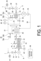
- a combined cycle plant of the present embodiment includes a gas turbine installation G, a steam turbine installation S, and a control device 50.
- the gas turbine installation G includes a gas turbine 10, a GT generator 17 that generates electricity by the gas turbine 10 drive, a GT circuit breaker 18 that electrically connects and disconnects the GT generator 17 to and from a power system 1, a waste heat recovery boiler 20 that generates steam from heat from exhaust gas EG exhausted from the gas turbine 10, and a stack 29 that discharges the exhaust gas EG that has passed through the waste heat recovery boiler 20 to the atmosphere.
- the gas turbine 10 includes a compressor 11 that compresses air A, a combustor 14 that burns fuel F in the air compressed by the compressor 11 to generate combustion gas, and a turbine 12 that is driven by the high-temperature and high-pressure combustion gas.
- a turbine rotor of the turbine 12 and a compressor rotor of the compressor 11 are connected to each other to form a gas turbine rotor 13.
- a rotor of the GT generator 17 is connected to the gas turbine rotor 13.
- a fuel line 15 is connected to the combustor 14 to supply the fuel F from an external fuel supply source to the combustor 14.
- the fuel line 15 is provided with a fuel control valve 16 that adjusts a flow rate of the fuel F to be supplied to the combustor 14.
- the waste heat recovery boiler 20 is connected to an exhaust port of the turbine 12 via a flue gas duct 25.
- the stack 29 is provided at an exhaust port of the waste heat recovery boiler 20.
- the GT generator 17 is electrically connected to the power system 1 by a power line 19.
- the power line 19 is provided with the GT circuit breaker 18.
- the GT circuit breaker 18 electrically connects the GT generator 17 to the power system 1 in response to a command from the outside, and electrically disconnects the GT generator 17 from the power system 1 in response to a command from the outside.
- the gas turbine installation G further includes a GT output gauge 41 capable of detecting a gas turbine output, which is the power generated by the GT generator 17, and a GT rotational speed meter 42 capable of detecting the rotational speed of the gas turbine rotor 13.
- the steam turbine installation S includes the waste heat recovery boiler 20, the stack 29, a steam turbine 30 driven by the steam generated by the waste heat recovery boiler 20, an ST generator 37 that generates electricity by the steam turbine 30 drive, an ST circuit breaker 38 that electrically connects and disconnects the ST generator 37 to and from the power system 1, a condenser 34 that returns the steam exhausted from the steam turbine 30 to water, and a feedwater pump 35 that returns the water in the condenser 34 to the waste heat recovery boiler 20.
- the waste heat recovery boiler 20 and the stack 29 are common devices for the gas turbine installation G and the steam turbine installation S.
- a steam turbine rotor 33 is connected to a rotor of the ST generator 37.
- the steam turbine rotor 33 is not mechanically connected to the gas turbine rotor 13. Therefore, the rotation of the gas turbine rotor 13 is not synchronized with the rotation of the steam turbine rotor 33.
- the gas turbine rotor 13 is rotating does not necessarily mean that the steam turbine rotor 33 is rotating.
- the ST generator 37 is electrically connected to the power system 1 by a power line 39.
- the power line 39 is provided with the ST circuit breaker 38.
- the ST circuit breaker 38 electrically connects the ST generator 37 to the power system 1 in response to a command from the outside, and electrically disconnects the ST generator 37 from the power system 1 in response to a command from the outside.
- a steam inlet of the steam turbine 30 and a steam outlet of the waste heat recovery boiler 20 are connected by a main steam line 21.
- the main steam line 21 is provided with a steam control valve 22 that adjusts the flow rate of steam flowing into the steam turbine 30.
- the steam control valve 22 includes a shut-off valve 22a capable of shutting off the steam flowing into the steam turbine 30 and a control valve 22b capable of adjusting the flow rate of the steam flowing into the steam turbine 30.
- the control valve 22b is disposed in the main steam line 21 closer to the steam turbine 30 than the shut-off valve 22a.
- a steam outlet of the steam turbine 30 is connected to a steam inlet of the condenser 34.
- a bypass line 23 is branched from a position in the main steam line 21 closer to the waste heat recovery boiler 20 than the steam control valve 22.
- the bypass line 23 is connected to the steam inlet of the condenser 34.
- the bypass line 23 is provided with a bypass valve 24 that adjusts a flow rate of steam flowing through the bypass line 23.
- a feedwater line 36 connects a condensate outlet of the condenser 34 and a water inlet of the waste heat recovery boiler 20.
- the feedwater pump 35 is provided in the feedwater line 36.
- a desuperheater 26 capable of adjusting the temperature of the steam flowing into the steam turbine 30 is provided at a position in the main steam line 21 closer to the waste heat recovery boiler 20 than the branch position of the bypass line 23.
- the desuperheater 26 includes a spray 26s capable of spraying water at a position in the main steam line 21 closer to the waste heat recovery boiler 20 than the branch position of the bypass line 23, and a spray amount control valve 26v capable of adjusting an amount of water sprayed from the spray 26s.
- the steam turbine installation S further includes an ST generator output gauge 45 capable of detecting a steam turbine output, which is the power generated by the ST generator 37, an ST rotational speed meter 46 capable of detecting the rotational speed of the steam turbine rotor 33, a thermometer 47 capable of detecting the temperature of the steam flowing through the main steam line 21, and a pressure gauge 48 capable of detecting the pressure of the steam flowing through the main steam line 21.
- the thermometer 47 and the pressure gauge 48 are provided at positions in the main steam line 21 closer to the steam turbine 30 than the branch position of the bypass line 23 and closer to the waste heat recovery boiler 20 than the steam control valve 22.
- the control device 50 is a computer.
- the control device 50 includes a central processing unit (CPU) 60 that executes various operations, a memory 57 that serves as a work area for the CPU 60 or the like, an auxiliary storage device 58 such as a hard disk drive device, a manual input device (input device) 51 such as a keyboard or a mouse, a display device (output device) 52, an input/output interface 53 for the manual input device 51 and the display device 52, a device interface (input device) 54 for transmitting and receiving data to and from various devices, a communication interface (input/output device) 55 for communicating with the outside via a network N, and a storage/playback device (input/output device) 56 that executes data storage processing and playback processing for a disk storage medium D.
- CPU central processing unit
- memory 57 that serves as a work area for the CPU 60 or the like
- an auxiliary storage device 58 such as a hard disk drive device
- the device interface 54 receives detection data from the GT output gauge 41, the GT rotational speed meter 42, the ST generator output gauge 45, the ST rotational speed meter 46, the thermometer 47, and the pressure gauge 48.
- the device interface 54 transmits control data to the circuit breakers 18 and 38, the fuel control valve 16, the shut-off valve 22a, the control valve 22b, the bypass valve 24, and the spray amount control valve 26v.
- the auxiliary storage device 58 stores in advance a control program 58p for the combined cycle plant.
- a start-up control program 58pa that controls start-up of the combined cycle plant is incorporated in the control program 58p.
- the control program 58p is loaded into the auxiliary storage device 58 from the disk storage medium D via the storage/playback device 56, for example.
- a new start-up control program 58pa is loaded into the auxiliary storage device 58 from the disk storage medium D via the storage/playback device 56, for example.
- the program may be loaded into the auxiliary storage device 58 from an external device via the communication interface 55.
- the CPU 60 functionally includes a start-up control unit 60g for the gas turbine installation G and a start-up control unit 60s for the steam turbine installation S.
- the start-up control unit 60g of the gas turbine installation G includes a GT start-up mode reception unit 61, a GT start-up fuel control unit 62, and a GT synchronization command unit 63.
- the start-up control unit 60s of the steam turbine installation S includes an ST generator output control unit 71, a steam pressure control unit 72, an ST bypass steam pressure control unit 73, an ST synchronization command unit 74, a steam temperature control unit 75, a steam admission command unit 76, a steam supply stop command unit 77, a thermal stress estimating unit 78, and a thermal stress detection unit 79.
- All of the functional units 61 to 63 and 71 to 79 function when the CPU 60 executes the start-up control program 58pa stored in the auxiliary storage device 58.
- the functional contents of the functional units 61 to 63 and 71 to 79 will be described in the process of describing the operation of the control device 50.
- the GT rapid start-up mode is a mode in which the gas turbine 10 is started rapidly by increasing the output of the gas turbine 10 to the rated output regardless of the state of the steam turbine 30.
- the GT normal start-up mode is a mode in which the gas turbine 10 is not started rapidly.
- the GT start-up mode reception unit 61 of the control device 50 receives the start-up mode of the gas turbine 10 from the outside (S10: GT start-up mode reception step).
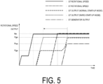
- the GT start-up fuel control unit 62 executes a GT normal start-up step (S 11N). In the GT normal start-up step (S 11N), until the GT generator 17 is synchronized to the power system 1, as shown in FIG.
- the GT start-up fuel control unit 62 commands the fuel control valve 16 on a flow rate of fuel to be supplied to the gas turbine 10 so that the rotational speed of the gas turbine 10 detected by the GT rotational speed meter 42 changes according to a predetermined rotational speed change pattern (solid line in FIG. 5 ).
- a predetermined rotational speed change pattern solid line in FIG. 5 .
- the GT start-up fuel control unit 62 commands the fuel control valve 16 on the flow rate of the fuel to be supplied to the gas turbine 10 so that the gas turbine output detected by the GT output gauge 41 (long dashed line in FIG. 5 ) changes according to a predetermined normal output change pattern, as shown in FIG. 5 .
- the flow rate of the fuel supplied to the gas turbine 10 increases.
- the temperature of the steam generated from the waste heat recovery boiler 20 gradually increases, and the amount of the generated steam gradually increases.
- the GT synchronization command unit 63 of the control device 50 commands the GT circuit breaker 18 to electrically connect the GT generator 17 to the power system 1 (S12: GT synchronization step).
- the GT generator 17 is synchronized to the power system 1, and the gas turbine output can be detected by the GT output gauge 41.
- the GT start-up fuel control unit 62 commands the fuel control valve 16 on the flow rate of the fuel to be supplied to the gas turbine 10 so that the gas turbine output detected by the GT output gauge 41 changes according to the predetermined normal output change pattern.
- the normal output change pattern is set so that when the gas turbine output reaches a low output Pga lower than the rated output Pgn, the low output Pga is maintained for a predetermined time.
- the GT start-up fuel control unit 62 commands the fuel control valve 16 on the flow rate of the fuel to be supplied to the gas turbine 10 so that the low output Pga is maintained (S11Na).
- the normal output change pattern is set so that after the low output Pga is maintained for the predetermined time, the gas turbine output gradually increases from the low output Pga to the rated output Pgn.
- the GT start-up fuel control unit 62 commands the fuel control valve 16 on the flow rate of the fuel to be supplied to the gas turbine 10 so that the gas turbine output (long dashed line in FIG. 5 ) is gradually increased to the rated output Pgn.
- the operation of the GT start-up fuel control unit 62 causes the gas turbine output to reach the rated output Pgn (S 13).
- the GT start-up fuel control unit 62 adjusts the gas turbine output (S11Nb), regardless of the normal output change pattern, as part of the GT normal start-up step (S 11N). Specifically, when the thermal stress generated in the steam turbine 30 reaches or exceeds the predetermined thermal stress, the GT start-up fuel control unit 62 commands the fuel control valve 16 to temporarily reduce the flow rate of the fuel to be supplied to the gas turbine 10. As a result, the gas turbine output falls below the gas turbine output indicated by the normal output change pattern.
- any one of the temperature, the pressure, and the flow rate of the steam flowing into the steam turbine 30 becomes smaller, and the thermal stress generated in the steam turbine 30 falls below the predetermined thermal stress.
- the GT start-up fuel control unit 62 again commands the fuel control valve 16 on the flow rate of the fuel to be supplied to the gas turbine 10 so that the gas turbine output changes according to the normal output change pattern.
- the steam temperature control unit 75 of the control device 50 commands the desuperheater 26 so that the temperature of the steam detected by the thermometer 47 does not exceed a predetermined temperature at least until the steam turbine output reaches a rated output (S20: steam temperature control step).
- S20 steam temperature control step
- the spray amount control valve 26v of the desuperheater 26 receives the command, the amount of water sprayed from the spray 26s to the main steam line 21 becomes an amount of water sprayed corresponding to the command.
- the temperature of the steam at a position in the main steam line 21 closer to the steam turbine 30 than a position where the desuperheater 26 is provided does not exceed the predetermined temperature.
- the ST bypass steam pressure control unit 73 of the control device 50 commands the bypass valve 24 to open (S21: ST bypass steam pressure control step) when the steam pressure detected by the pressure gauge 48 reaches or exceeds a predetermined value (which may not be a fixed value) at least until the steam turbine output reaches the rated output.
- a predetermined value which may not be a fixed value
- the bypass valve 24 opens, and some of the steam from the waste heat recovery boiler 20 is sent to the condenser 34 via the bypass line 23.
- the steam admission command unit 76 of the control device 50 commands the steam control valve 22 to open so that the steam supply to the steam turbine 30 is started (S22: steam admission step).
- S22 steam admission step
- the steam generated in the waste heat recovery boiler 20 flows into the steam turbine 30 via the main steam line 21 and the steam control valve 22.
- the steam turbine 30 begins to be driven by the steam.
- the steam admission step (S22) is basically executed after the GT synchronization step (S12).
- the thermal stress estimating unit 78 of the control device 50 estimates the thermal stress generated in the steam turbine 30 at least until the steam turbine output reaches the rated output (S23: thermal stress estimation step).
- S23 thermal stress estimation step.
- the thermal stress estimating unit 78 first estimates the temperature in the portion in the vicinity of the inlet at the present time from the temperature of the steam detected by the thermometer 47, and obtains the temperature differential between this temperature and the temperature in the portion of the vicinity of the inlet estimated a predetermined time ago. Then, the thermal stress estimating unit 78 obtains the thermal stress of the portion in the vicinity of the inlet based on the temperature differential, the shape of the portion in the vicinity of the inlet, the Young's modulus and the expansion coefficient of the material forming the portion in the vicinity of the inlet, and the like. The thermal stress estimated by the thermal stress estimating unit 78 is used when adjusting the gas turbine output described above (S11Nb).
- the steam pressure control unit 72 of the control device 50 commands the control valve 22b of the steam control valve 22 on the degree of opening so that the flow rate of steam flowing into the steam turbine 30 gradually increases, and commands the bypass valve 24 on the degree of opening so that the steam pressure detected by the pressure gauge 48 increases according to a predetermined pressure change pattern (S24: steam pressure control step).
- the ST synchronization command unit 74 of the control device 50 commands the ST circuit breaker 38 to electrically connect the ST generator 37 to the power system 1 (S26: ST synchronization step).
- the ST generator 37 is synchronized to the power system 1, and the steam turbine output can be detected by the ST generator output gauge 45.
- the steam pressure control step (S24) is still executed, and as shown in FIG. 5 , the steam turbine output (two-dot chain line in FIG. 5 ) reaches a rated output Psn.
- control device 50 in the GT rapid start-up mode will be described with reference to the flowchart shown in FIG. 4 .
- the GT start-up mode reception unit 61 of the control device 50 receives the start-up mode of the gas turbine 10 from the outside (S 10: GT start-up mode reception step).
- the GT start-up fuel control unit 62 executes a GT rapid start-up step (S11Q). Also in the GT rapid start-up step (S11Q), as in the GT normal start-up step (S11N), until the GT generator 17 is synchronized to the power system 1, as shown in FIG.
- the GT start-up fuel control unit 62 commands the fuel control valve 16 on the flow rate of the fuel to be supplied to the gas turbine 10 so that the rotational speed of the gas turbine 10 detected by the GT rotational speed meter 42 (solid line in FIG. 5 ) changes according to the predetermined rotational speed change pattern.
- the flow rate of the fuel supplied to the gas turbine 10 increases.
- the temperature of the steam generated from the waste heat recovery boiler 20 gradually increases, and the amount of the generated steam gradually increases.
- the GT start-up fuel control unit 62 commands the fuel control valve 16 on the flow rate of the fuel to be supplied to the gas turbine 10 so that the gas turbine output detected by the GT output gauge 41 (short dashed line in FIG. 5 ) changes according to a predetermined rapid output change pattern, as shown in FIG. 5 .
- the rapid output change pattern is set so that the gas turbine output changes linearly over time.
- the flow rate of the fuel supplied to the gas turbine 10 gradually increases over time.
- the temperature of the steam generated from the waste heat recovery boiler 20 gradually increases, and the amount of the generated steam gradually increases.
- the GT synchronization command unit 63 of the control device 50 commands the GT circuit breaker 18 to electrically connect the GT generator 17 to the power system 1 (S12: GT synchronization step).
- the GT generator 17 is synchronized to the power system 1, and the gas turbine output can be detected by the GT output gauge 41.
- the GT rapid start-up step (S11Q) is still executed, and as shown in FIG. 5 , the gas turbine output (short dashed line in FIG. 5 ) reaches the rated output Pgn.
- the steam temperature control unit 75 of the control device 50 commands the desuperheater 26 so that the temperature of the steam detected by the thermometer 47 does not exceed the predetermined temperature at least until the steam turbine output reaches the rated output (S20: steam temperature control step).
- the spray amount control valve 26v of the desuperheater 26 receives the command, the spray 26s sprays the amount of water corresponding to the command to the main steam line 21.
- the ST bypass steam pressure control unit 73 of the control device 50 commands the bypass valve 24 to open (S21: ST bypass steam pressure control step) when the steam pressure detected by the pressure gauge 48 reaches or exceeds the predetermined value (which may not be a fixed value), at least until the steam turbine output reaches the rated output.
- the predetermined value which may not be a fixed value
- the bypass valve 24 opens, and some of the steam from the waste heat recovery boiler 20 is sent to the condenser 34 via the bypass line 23.
- the steam admission command unit 76 of the control device 50 commands the steam control valve 22 to open so that the steam supply to the steam turbine 30 is started (S22: steam admission step).
- the steam generated in the waste heat recovery boiler 20 flows into the steam turbine 30 via the main steam line 21 and the steam control valve 22.
- the steam turbine 30 begins to be driven by the steam.
- the steam admission step (S22) is executed after the GT synchronization step (S12) described above is executed and the gas turbine output reaches the rated output Pgn (S13), that is, after the GT rapid start-up step (S11Q) is completed.
- the thermal stress estimating unit 78 of the control device 50 estimates the thermal stress generated in the steam turbine 30 at least until the steam turbine output reaches the rated output (S23: thermal stress estimation step).
- the steam supply stop command unit 77 of the control device 50 executes a steam supply stop step (S25) during a period from the start of steam supply to the steam turbine 30 to the execution of the ST synchronization step (S26) described later.
- the steam supply stop command unit 77 first detects whether the thermal stress estimated in the thermal stress estimation step (S23) has reached or exceeded a predetermined second thermal stress (S25a). Then, when the steam supply stop command unit 77 detects that the thermal stress estimated in the thermal stress estimation step (S23) has reached or exceeded the predetermined second thermal stress, the steam supply stop command unit 77 commands the steam control valve 22 to close the valve (S25b) so that the steam supply to the steam turbine 30 is stopped.
- the time during which the thermal stress occurs can be minimized, thereby minimizing deterioration of the steam turbine 30 due to the thermal stress.
- the ST synchronization command unit 74 of the control device 50 commands the ST circuit breaker 38 to electrically connect the ST generator 37 to the power system 1 (S26: ST synchronization step).
- the ST generator 37 is synchronized to the power system 1, and the steam turbine output can be detected by the ST generator output gauge 45.
- the ST generator output control unit 71 of the control device 50 executes an ST generator output control step (S27).
- the ST generator output control unit 71 commands the control valve 22b on the degree of opening to control the flow rate of the steam flowing into the steam turbine 30 so that the output of the ST generator 37, that is, the steam turbine output, increases according to the target output change pattern (S27a).
- the target output change pattern is set so that the thermal stress generated in the steam turbine 30 does not reach the predetermined first thermal stress.
- the first thermal stress may have the same value as the second thermal stress described above, or may have a different value from the second thermal stress described above.
- the ST generator output control unit 71 detects whether the thermal stress estimated in the thermal stress estimation step (S23) has reached or exceeded the predetermined first thermal stress (S27b).
- the ST generator output control unit 71 detects that the thermal stress estimated in the thermal stress estimation step (S23) has reached or exceeded the predetermined first thermal stress, as part of the ST generator output control step (S27), the ST generator output control unit 71 commands the control valve 22b on the degree of opening to adjust the flow rate of the steam flowing into the steam turbine 30 so that the change in the steam turbine output is smaller than the change indicated by the target output change pattern (S27c). At this time, the ST generator output control unit 71 controls the flow rate of the steam flowing into the steam turbine 30 so that the steam turbine output is temporarily maintained.
- the thermal stress detection unit 79 of the control device 50 executes a thermal stress detection step (S28).
- the thermal stress detection unit 79 detects whether the thermal stress has reached a stable thermal stress state in which an amount of change per unit time of the thermal stress estimated in the thermal stress estimation step (S23) is smaller than a predetermined amount of change and the thermal stress at the present time is smaller than the first thermal stress.
- the ST generator output control step (S27) is continued.
- the ST generator output control step (S27) is completed, and the steam pressure control unit 72 of the control device 50 executes a steam pressure control step (S29).
- the steam pressure control step (S29) as in the steam pressure control step (S24) described with reference to FIG.
- the steam pressure control unit 72 commands the control valve 22b of the steam control valve 22 on the degree of opening so that the flow rate of the steam flowing into the steam turbine 30 gradually increases, and commands the bypass valve 24 on the degree of opening so that the steam pressure detected by the pressure gauge 48 increases according to the predetermined pressure change pattern.
- the gas turbine output (long dashed line in FIG. 5 ) is maintained at the low output Pga lower than the rated output Pgn for the predetermined time so that the thermal stress generated in the steam turbine 30 is not high.
- the amount of steam supplied to the steam turbine 30 per unit time has a positive correlation with the steam turbine output.
- the thermal stress in the steam turbine 30 has a positive correlation with the steam turbine output.
- the GT start-up mode reception unit 61 when the GT start-up mode reception unit 61 receives the GT rapid start-up mode, unlike when the GT start-up mode reception unit 61 receives the GT normal start-up mode, there is no need to maintain the gas turbine output at the low output Pga for the predetermined time.
- the time required for the gas turbine output to reach the rated output Pgn can be shorter than when the GT start-up mode reception unit 61 receives the GT normal start-up mode, while suppressing the thermal stress generated in the steam turbine 30.
- the time required for the gas turbine output to reach the rated output Pgn can be shorter than when the gas turbine output is maintained at the low output for the predetermined time, while suppressing the thermal stress generated in the steam turbine 30.
- a combined cycle plant of the present embodiment includes a first gas turbine installation Ga, a second gas turbine installation Gb, a steam turbine installation Sa, and a control device 50a.
- the first gas turbine installation Ga includes a first gas turbine 10a, a first GT generator 17a, a first GT circuit breaker 18a, a first waste heat recovery boiler 20a, and a first stack 29a.
- the second gas turbine installation Gb includes a second gas turbine 10b, a second GT generator 17b, a second GT circuit breaker 18b, a second waste heat recovery boiler 20b, and a second stack 29b.
- the steam turbine installation Sa in the present embodiment similarly to the steam turbine installation S in the first embodiment, for the first gas turbine installation Ga, includes the first waste heat recovery boiler 20a, which is a common device with the first gas turbine installation Ga, a steam turbine 30, an ST generator 37, an ST circuit breaker 38, a condenser 34, a feedwater pump 35, a first main steam line 21a, a steam control valve 22, a bypass line 23, a bypass valve 24, a feedwater line 36, a first desuperheater 26a, an ST generator output gauge 45, an ST rotational speed meter 46, a thermometer 47, and a pressure gauge 48.
- the first main steam line 21a connects a steam outlet of the first waste heat recovery boiler 20a and a steam inlet of the steam turbine 30.
- the steam turbine installation Sa of the present embodiment further includes the second waste heat recovery boiler 20b, which is a common device with the second gas turbine installation Gb, a second main steam line 21b, a second desuperheater 26b, a first switching valve 28a, and a second switching valve 28b.
- the second main steam line 21b connects a steam outlet of the second waste heat recovery boiler 20b and the steam inlet of the steam turbine 30. Accordingly, the second main steam line 21b and the first main steam line 21a share a portion on the steam turbine 30 side.
- the portion shared by the second main steam line 21b and the first main steam line 21a is referred to as a shared main steam line 21c.
- a portion of the second main steam line 21b excluding the shared main steam line 21c is referred to as a second main steam dedicated line 21bd, and a portion of the first main steam line 21a excluding the shared main steam line 21c is referred to as a first main steam dedicated line 21ad.
- the steam control valve 22 is provided in the shared main steam line 21c.
- a second switching valve 28b is provided in the second main steam dedicated line 21bd.
- a first switching valve 28a is provided at a position in the first main steam dedicated line 21ad closer to the first waste heat recovery boiler 20a than a branch position of the bypass line 23.
- the first switching valve 28a When the first gas turbine 10a is started and the second gas turbine 10b is not started, the first switching valve 28a is open and the second switching valve 28b is closed. Thus, the steam generated in the first waste heat recovery boiler 20a by starting up the first gas turbine 10a flows into the steam turbine 30 via the first main steam line 21a.
- the bypass valve 24 opens, and some of the steam generated in the first waste heat recovery boiler 20a is sent to the condenser 34 via the bypass line 23.
- the first switching valve 28a When the first gas turbine 10a is not started and the second gas turbine 10b is started, the first switching valve 28a is closed and the second switching valve 28b is open.
- the steam generated in the second waste heat recovery boiler 20b by starting up the second gas turbine 10b flows into the steam turbine 30 via the second main steam line 21b.
- the bypass valve 24 opens, and some of the steam generated in the second waste heat recovery boiler 20b is sent to the condenser 34 via the bypass line 23.
- the first switching valve 28a and the second switching valve 28b are both open.
- the steam generated in the first waste heat recovery boiler 20a by starting up the first gas turbine 10a flows into the steam turbine 30 via the first main steam line 21a
- the steam generated in the second waste heat recovery boiler 20b flows into the steam turbine 30 via the second main steam line 21b.
- the bypass valve 24 opens, and some of the steam generated in the first waste heat recovery boiler 20a or some of the steam generated in the second waste heat recovery boiler 20b is sent to the condenser 34 via the bypass line 23.
- the control device 50a is a computer like the control device 50 of the first embodiment.
- the control device 50a functionally includes a start-up control unit for the first gas turbine installation Ga, a start-up control unit for the second gas turbine installation Gb, and a start-up control unit for the steam turbine installation S.
- Both the start-up control unit for the first gas turbine installation Ga and the start-up control unit for the second gas turbine installation Gb have the same configuration as the start-up control unit 60g in the control device 50 of the first embodiment.
- the start-up control unit for the steam turbine installation S has basically the same configuration as the start-up control unit 60s in the control device 50 of the first embodiment.
- the start-up control unit for the steam turbine installation S in the present embodiment further includes a switching control unit that controls opening and closing of the first switching valve 28a and the second switching valve 28b.
- the time required for the gas turbine output to reach the rated output Pgn can be shorter than when the GT start-up mode reception unit 61 receives the GT normal start-up mode, while suppressing the thermal stress generated in the steam turbine 30.
- the combined cycle plant of the present embodiment is a plant including two gas turbine installations Ga and Gb for one steam turbine installation S.
- the combined cycle plant may be a plant including three or more gas turbine installations G for one steam turbine installation S.
- Each of the control devices 50 and 50a in the above embodiments includes the GT start-up mode reception unit 61.
- the GT rapid start-up step (S11Q) is executed, and when the GT start-up mode reception unit 61 receives the GT normal start-up mode, the GT normal start-up step (S 11N) is executed.
- the control device that does not include the GT start-up mode reception unit 61 may be used. In this case, the control device executes a GT start-up step similar to the GT rapid start-up step (S11Q) in each of the embodiments.
- control devices 50 and 50a in the embodiments is configured by one computer.
- the control device may be configured by a computer for the gas turbine installation and a computer for the steam turbine installation. In this case, the two computers need to be able to communicate with each other via a local network or the like.
- the control device may be functionally configured by a controller having only the function of the ST bypass steam pressure control unit 73 and a controller having only the function of the steam temperature control unit 75 in addition to the computer including the GT start-up fuel control unit 62, the ST generator output control unit 71, the steam pressure control unit 72, and the like.
- the combined cycle plant includes a gas turbine 10 configured to be driven by fuel supply, a waste heat recovery boiler 20 configured to generate steam by using heat from exhaust gas exhausted from the gas turbine 10, a steam turbine 30 configured to be driven by the steam from the waste heat recovery boiler 20, a condenser 34 configured to return the steam exhausted from the steam turbine 30 to water, and a generator configured to generate electricity by the steam turbine 30 drive.
- the method for starting up a combined cycle plant includes a gas turbine start-up step of increasing an output of the gas turbine 10 to a rated output by supplying fuel to the gas turbine 10, a steam admission step (S22) of, when a temperature of the steam from the waste heat recovery boiler 20 reaches or exceeds a predetermined temperature, starting steam supply to the steam turbine 30, a synchronization step (S26) of, after the steam admission step (S22), when a rotational speed of the steam turbine 30 reaches a rated rotational speed, synchronizing the generator to a power system 1, an ST generator output control step (S27) of, after the generator is synchronized, controlling a flow rate of the steam flowing into the steam turbine 30 so that an output of the generator increases according to a target output change pattern, and a thermal stress estimation step (S23) of estimating a thermal stress generated in the steam turbine 30 based on a temperature of the steam flowing into the steam turbine 30.
- the flow rate of the steam flowing into the steam turbine 30 is controlled so that a change in the output of the generator is smaller than a change indicated by the target output change pattern.
- An amount of steam supplied to the steam turbine 30 per unit time has a positive correlation with a steam turbine output that is the output of the generator.
- the thermal stress in the steam turbine 30 has a positive correlation with the steam turbine output for a predetermined time after the generator connected to the steam turbine 30 is synchronized to the power system 1.
- the flow rate of the steam flowing into the steam turbine 30 is controlled based on the steam turbine output so that the thermal stress generated in the steam turbine 30 does not reach or exceed the predetermined thermal stress. Therefore, in this aspect, there is no need to maintain the gas turbine output at a low output lower than the rated output for a predetermined time to prevent the thermal stress generated in the steam turbine 30 from becoming too high.
- the time required for the gas turbine output to reach the rated output can be shorter than when the gas turbine output is maintained at the low output for the predetermined time, while suppressing the thermal stress generated in the steam turbine 30.
- a method for starting up a combined cycle plant according to a third aspect further includes an ST bypass steam pressure control step (S21) of, when a pressure of the steam flowing into the steam turbine 30 reaches or exceeds a predetermined value, sending some of the steam from the waste heat recovery boiler 20 to the condenser 34 without supplying the some of the steam to the steam turbine 30.
- ST bypass steam pressure control step S21 of, when a pressure of the steam flowing into the steam turbine 30 reaches or exceeds a predetermined value, sending some of the steam from the waste heat recovery boiler 20 to the condenser 34 without supplying the some of the steam to the steam turbine 30.
- the pressure of the steam flowing into the steam turbine 30 can be avoided from exceeding the predetermined pressure.
- a method for starting up a combined cycle plant according to a fourth aspect further includes a steam temperature control step (S20) of controlling the temperature of the steam from the waste heat recovery boiler 20 so that the temperature of the steam flowing into the steam turbine 30 does not exceed a predetermined temperature.
- the temperature of the steam flowing into the steam turbine 30 can be avoided from exceeding the predetermined temperature.
- a method for starting up a combined cycle plant according to a fifth aspect further includes, when the thermal stress estimated in the thermal stress estimation step (S23) reaches or exceeds a predetermined second thermal stress during a period from start of the steam supply to the steam turbine 30 to execution of the synchronization step (S26), a steam supply stop step (S25) of stopping the steam supply to the steam turbine 30.
- the target output change pattern used in the ST generator output control step (S27) is set so that the thermal stress generated in the steam turbine 30 does not reach the predetermined first thermal stress.
- a method for starting up a combined cycle plant according to a seventh aspect further includes a thermal stress detection step (S28) of detecting whether the thermal stress has reached a stable state in which an amount of change per unit time of the thermal stress estimated in the thermal stress estimation step (S23) is smaller than a predetermined amount of change and the thermal stress is smaller than the predetermined first thermal stress, and a steam pressure control step (S24) of, after the ST generator output control step (S27) is completed by detecting that the thermal stress has reached the stable state in the thermal stress detection step (S28), controlling the pressure of the steam flowing into the steam turbine 30 so that the pressure of the steam flowing into the steam turbine 30 is maintained within a predetermined range.
- the gas turbine start-up step is a GT rapid start-up step (S11Q) of increasing an output of the gas turbine 10 to a rated output regardless of a state of the steam turbine 30.
- the GT rapid start-up step (S11Q) ends before the steam admission step (S22).
- a method for starting up a combined cycle plant according to a tenth aspect further includes a GT start-up mode reception step (S10) of receiving a mode indicating whether to rapidly start up the gas turbine 10.
- a GT rapid start-up mode for rapidly starting up the gas turbine 10 is received in the GT start-up mode reception step (S10), the GT rapid start-up step (S11Q), the steam admission step (S22), the synchronization step (S26), the ST generator output control step (S27), and the thermal stress estimation step (S23) are performed.
- a method for starting up a combined cycle plant according to an 11th aspect further includes a GT normal start-up step (S11N) of, when a GT normal start-up mode in which the gas turbine 10 is not started rapidly is received in the GT start-up mode reception step (S10), increasing the output of the gas turbine 10 to a rated output by supplying fuel to the gas turbine 10, a steam admission step (S22) of, when a temperature of the steam from the waste heat recovery boiler 20 reaches or exceeds a predetermined temperature, starting steam supply to the steam turbine 30, a synchronization step (S26) of, after the steam admission step (S22), when a rotational speed of the steam turbine 30 reaches a rated rotational speed, synchronizing the generator to a power system 1, and a steam pressure control step (S24) of, after the generator is synchronized, controlling a pressure of the steam flowing into the steam turbine 30 so that the pressure of the steam flowing into the steam turbine 30
- a flow rate of the fuel to be supplied to the gas turbine 10 is adjusted before the output of the gas turbine 10 reaches the rated output, so as to temporarily maintain the output of the gas turbine 10 at a predetermined low output lower than the rated output.
- the GT normal start-up step (S 11N) can be included.
- the thermal stress estimation step (S23) is performed.
- the thermal stress estimated in the thermal stress estimation step (S23) reaches or exceeds a predetermined thermal stress, the flow rate of the fuel to be supplied to the gas turbine 10 is temporarily reduced so that the output of the gas turbine 10 is temporarily reduced.
- the high thermal stress generated in the steam turbine 30 can be avoided during the GT normal start-up step (S 11N).
- a combined cycle plant includes a gas turbine 10 configured to be driven by fuel supply, a waste heat recovery boiler 20 configured to generate steam by using heat from exhaust gas exhausted from the gas turbine 10, a steam turbine 30 configured to be driven by the steam from the waste heat recovery boiler 20, a condenser 34 configured to return the steam exhausted from the steam turbine 30 to water, a generator 37 configured to generate electricity by the steam turbine 30 drive, a circuit breaker 38 configured to electrically connect the generator 37 to a power system 1 in response to an external command and to electrically disconnect the generator 37 from the power system 1 in response to an external command, a fuel control valve 16 configured to adjust a flow rate of fuel to be supplied to the gas turbine 10, a main steam line 21 configured to guide the steam from the waste heat recovery boiler 20 to the steam turbine 30, a steam control valve 22 provided in the main steam line 21 and configured to adjust a flow rate of the steam flowing into the steam turbine 30, a thermometer 47 provided in the main steam line 21 closer to the waste heat recovery boiler 20 than the steam control valve 22 and configured
- the control device 50 includes start-up fuel control unit 62 configured to command the fuel control valve 16 to start fuel supply to the gas turbine 10 and command the fuel control valve 16 on a flow rate of fuel to be supplied to the gas turbine 10 so that the output of the gas turbine 10 increases to a rated output, a steam admission command unit 76 configured to command the steam control valve 22 to open so as to start steam supply to the steam turbine 30 when the temperature of the steam detected by the thermometer 47 reaches or exceeds a predetermined temperature, a synchronization command unit 74 configured to command the circuit breaker 38 to electrically connect the generator 37 to the power system 1 when the rotational speed detected by the rotational speed meter reaches a rated rotational speed of the steam turbine 30, an ST generator output control unit 71 configured to command the steam control valve 22 on a flow rate of the steam to flow into the steam turbine 30 after the generator 37 is electrically connected to the power system 1 so that the output detected by the output gauge 45 increases according to a target output change pattern, and a thermal stress estimating unit 78 configured to estimate
- the ST generator output control unit 71 commands the steam control valve 22 on the flow rate of the steam to flow into the steam turbine 30 so that the change in the output detected by the output gauge 45 is smaller than a change indicated by the target output change pattern.
- the time required for the gas turbine output to reach the rated output can be shorter than when the gas turbine output is maintained at the low output for the predetermined time, while suppressing the thermal stress generated in the steam turbine 30.
- a combined cycle plant according to a 14th aspect further includes a pressure gauge 48 provided in the main steam line 21 closer to the waste heat recovery boiler 20 than the steam control valve 22 and configured to detect a pressure of the steam flowing through the main steam line 21, a bypass line 23 extending from a position in the main steam line 21 closer to the waste heat recovery boiler 20 than a position where the steam control valve 22 is provided and configured to guide the steam from the waste heat recovery boiler 20 to the condenser 34, and a bypass valve 24 provided in the bypass line 23 and configured to adjust a flow rate of the steam flowing through the bypass line 23.
- the control device 50 includes an ST bypass steam pressure control unit 73 configured to command the bypass valve 24 to open when the pressure of the steam detected by the pressure gauge 48 reaches or exceeds a predetermined value.
- the pressure of the steam flowing into the steam turbine 30 can be avoided from exceeding the predetermined pressure.
- a combined cycle plant according to a 15th aspect further includes a desuperheater 26 configured to adjust the temperature of the steam flowing into the steam turbine 30 at a position in the main steam line 21 closer to the waste heat recovery boiler 20 than a position where the steam control valve 22 is provided.
- the control device 50 includes a steam temperature control unit 75 configured to command the desuperheater 26 so that the temperature of the steam detected by the thermometer 47 does not exceed a predetermined temperature.
- the temperature of the steam flowing into the steam turbine 30 can be avoided from exceeding the predetermined temperature.
- start-up control program for a combined cycle plant can be understood, for example, as follows.
- a non-transitory computer-readable storage medium storing a start-up control program for a combined cycle plant according to a sixteenth aspect is applied to the following combined cycle plant.
- the combined cycle plant includes a gas turbine 10 configured to be driven by fuel supply, a waste heat recovery boiler 20 configured to generate steam by using heat from exhaust gas exhausted from the gas turbine 10, a steam turbine 30 configured to be driven by the steam from the waste heat recovery boiler 20, a condenser 34 configured to return the steam exhausted from the steam turbine 30 to water, a generator 37 configured to generate electricity by the steam turbine 30 drive, a circuit breaker 38 configured to electrically connect the generator 37 to a power system 1 in response to an external command and to electrically disconnect the generator 37 from the power system 1 in response to an external command, a fuel control valve 16 configured to adjust a flow rate of fuel to be supplied to the gas turbine 10, a main steam line 21 configured to guide the steam from the waste heat recovery boiler 20 to the steam turbine 30, a steam control valve 22 provided in the main steam line 21 and configured to adjust a flow rate of the steam flowing into the steam turbine 30, a thermometer 47 provided in the main steam line 21 closer to the waste heat recovery boiler 20 than the steam control valve 22 and configured to detect a temperature of the steam
- the start-up control program for the combined cycle plant causes a computer to execute a gas turbine start-up step (S11Q) of commanding the fuel control valve 16 to start fuel supply to the gas turbine 10 and commanding the fuel control valve 16 on a flow rate of fuel to be supplied to the gas turbine 10 so that the output of the gas turbine 10 increases to a rated output, a steam admission step (S22) of, when the temperature of the steam detected by the thermometer 47 reaches or exceeds a predetermined temperature, commanding the steam control valve 22 to open so as to start steam supply to the steam turbine 30, a synchronization step (S26) of, when the rotational speed detected by the rotational speed meter reaches a rated rotational speed of the steam turbine 30, commanding the circuit breaker 38 to electrically connect the generator 37 to the power system 1, an ST generator output control step (S27) of, after the generator 37 is electrically connected to the power system 1, commanding the steam control valve 22 on a flow rate of the steam to flow into the steam turbine 30 so that the output detected by the output
- the thermal stress estimated in the thermal stress estimation step (S23) reaches or exceeds a predetermined value
- the flow rate of the steam to flow into the steam turbine 30 is commanded to the steam control valve 22 so that a change in the output detected by the output gauge 45 is smaller than a change indicated by the target output change pattern.
- the time required for the gas turbine output to reach the rated output can be shorter than when the gas turbine output is maintained at the low output for the predetermined time, while suppressing the thermal stress generated in the steam turbine 30.
- the gas turbine output can be brought to the rated output in a short period of time while suppressing the thermal stress generated in the steam turbine.
Landscapes
- Engineering & Computer Science (AREA)
- Chemical & Material Sciences (AREA)
- Combustion & Propulsion (AREA)
- Mechanical Engineering (AREA)
- General Engineering & Computer Science (AREA)
- Engine Equipment That Uses Special Cycles (AREA)
- Control Of Turbines (AREA)
Abstract
Description
- The present disclosure relates to a combined cycle plant including a gas turbine, a waste heat recovery boiler, and a steam turbine, a method for starting up the same, and a start-up control program for executing the method.
- This application claims priority based on
Japanese Patent Application No. 2020-164685 filed in Japan on September 30, 2020 - A combined cycle plant includes a gas turbine driven by fuel supply, a GT generator that generates electricity by the gas turbine drive, a waste heat recovery boiler that generates steam by using heat from exhaust gas exhausted from the gas turbine, a steam turbine driven by the steam from the waste heat recovery boiler, a condenser that returns the steam exhausted from the steam turbine to water, and an ST generator that generates electricity by drive of the steam turbine.
- As a method for starting up the combined cycle plant, for example, there is a method disclosed in
Patent Document 1 below. In this method for starting up, the gas turbine is first started, and after the rotational speed of the gas turbine reaches the rated rotational speed, the GT generator connected to the gas turbine is synchronized to the power system. Subsequently, when the gas turbine output (output of the GT generator) reaches the initial output, the amount of fuel to be supplied to the gas turbine is adjusted so that the initial output is maintained for a certain period of time. Subsequently, when the temperature of steam from the waste heat recovery boiler reaches or exceeds a predetermined temperature, the steam from the waste heat recovery boiler is gradually supplied to the steam turbine. Note that the predetermined temperature here is a temperature that is set as appropriate for starting up the steam turbine. Then, after the rotational speed of the steam turbine reaches the rated rotational speed, the ST generator connected to the steam turbine is synchronized to the power system. Subsequently, the amount of fuel to be supplied to the gas turbine is gradually increased to bring the gas turbine output to the rated output. In this process, the flow rate of the steam from the waste heat recovery boiler increases and the temperature of the steam also increases, so the steam turbine output also reaches the rated output. - When the gas turbine output is rapidly increased to the rated output, high temperature steam flows into the cooled steam turbine, thereby generating high thermal stress in the steam turbine. Thus, in the method for starting up, from the viewpoint of protecting the steam turbine, the gas turbine output is once maintained at the initial output lower than the rated output, and then increased to the rated output.
- Patent Document 1:
JP 58-197408 A - In the power generation industry, there is a demand for shortening the time from the start-up of the gas turbine until the gas turbine output reaches the rated output as much as possible.
- Accordingly, an object of the present disclosure is to provide a technique capable of increasing the gas turbine output to the rated output in a short period of time while suppressing the thermal stress generated in the steam turbine.
- A method for starting up a combined cycle plant as an aspect for achieving the above object is applied to the following combined cycle plant.
- The combined cycle plant includes a gas turbine configured to be driven by fuel supply, a waste heat recovery boiler configured to generate steam by using heat from exhaust gas exhausted from the gas turbine, a steam turbine configured to be driven by the steam from the waste heat recovery boiler, a condenser configured to return the steam exhausted from the steam turbine to water, and a generator configured to generate electricity by drive of the steam turbine.
- The method for starting up the combined cycle plant includes a gas turbine start-up step of increasing an output of the gas turbine to a rated output by supplying fuel to the gas turbine, a steam admission step of, when a temperature of the steam from the waste heat recovery boiler reaches or exceeds a predetermined temperature, starting steam supply to the steam turbine, a synchronization step of, after the steam admission step, when a rotational speed of the steam turbine reaches a rated rotational speed, synchronizing the generator to a power system, an ST generator output control step of, after the generator is synchronized, controlling a flow rate of the steam flowing into the steam turbine so that an output of the generator increases according to a target output change pattern, and a thermal stress estimation step of estimating a thermal stress generated in the steam turbine based on a temperature of the steam flowing into the steam turbine. In the ST generator output control step, when the thermal stress estimated in the thermal stress estimation step reaches or exceeds a predetermined first thermal stress, the flow rate of the steam flowing into the steam turbine is controlled so that a change in the output of the generator is smaller than a change indicated by the target output change pattern.
- An amount of steam supplied to the steam turbine per unit time has a positive correlation with a steam turbine output that is the output of the generator. In addition, the thermal stress in the steam turbine has a positive correlation with the steam turbine output for a predetermined time after the generator connected to the steam turbine is synchronized to the power system. Thus, in this aspect, the flow rate of the steam flowing into the steam turbine is controlled based on the steam turbine output so that the thermal stress generated in the steam turbine does not reach or exceed the predetermined thermal stress. Therefore, in this aspect, there is no need to maintain the gas turbine output at a low output lower than the rated output for a predetermined time to prevent the thermal stress generated in the steam turbine from becoming too high.
- Thus, in this aspect, the time required for the gas turbine output to reach the rated output can be shorter than when the gas turbine output is maintained at the low output for the predetermined time, while suppressing the thermal stress generated in the steam turbine.
- A combined cycle plant according to an aspect for achieving the object includes a gas turbine configured to be driven by fuel supply, a waste heat recovery boiler configured to generate steam by using heat from exhaust gas exhausted from the gas turbine, a steam turbine configured to be driven by the steam from the waste heat recovery boiler, a condenser configured to return the steam exhausted from the steam turbine to water, a generator configured to generate electricity by drive of the steam turbine, a circuit breaker configured to electrically connect the generator to a power system in response to an external command and to electrically disconnect the generator from the power system in response to an external command, a fuel control valve configured to adjust a flow rate of fuel to be supplied to the gas turbine, a main steam line configured to guide the steam from the waste heat recovery boiler to the steam turbine, a steam control valve provided in the main steam line and configured to adjust a flow rate of the steam flowing into the steam turbine, a thermometer provided in the main steam line closer to the waste heat recovery boiler than the steam control valve and configured to detect a temperature of the steam flowing through the main steam line, a rotational speed meter configured to detect a rotational speed of the steam turbine, an output gauge configured to detect an output that is an amount of power generated by the generator, and a control device. The control device includes a start-up fuel control unit configured to command the fuel control valve to start fuel supply to the gas turbine and command the fuel control valve on a flow rate of fuel to be supplied to the gas turbine so that an output of the gas turbine increases to a rated output, a steam admission command unit configured to command the steam control valve to open so as to start steam supply to the steam turbine when the temperature of the steam detected by the thermometer reaches or exceeds a predetermined temperature, a synchronization command unit configured to command the circuit breaker to electrically connect the generator to the power system when the rotational speed detected by the rotational speed meter reaches a rated rotational speed of the steam turbine, an ST generator output control unit configured to command the steam control valve on a flow rate of the steam to flow into the steam turbine after the generator is electrically connected to the power system so that the output detected by the output gauge increases according to a target output change pattern, and a thermal stress estimating unit configured to estimate thermal stress generated in the steam turbine based on the temperature of the steam detected by the thermometer. When the thermal stress estimated by the thermal stress estimating unit reaches or exceeds a predetermined value, the ST generator output control unit commands the steam control valve on the flow rate of the steam to flow into the steam turbine so that the change in the output detected by the output gauge is smaller than a change indicated by the target output change pattern.
- A start-up control program for a combined cycle plant as an aspect for achieving the above object is applied to the following combined cycle plant.
- The combined cycle plant includes a gas turbine configured to be driven by fuel supply, a waste heat recovery boiler configured to generate steam by using heat from exhaust gas exhausted from the gas turbine, a steam turbine configured to be driven by the steam from the waste heat recovery boiler, a condenser configured to return the steam exhausted from the steam turbine to water, a generator configured to generate electricity by drive of the steam turbine, a circuit breaker configured to electrically connect the generator to a power system in response to an external command and to electrically disconnect the generator from the power system in response to an external command, a fuel control valve configured to adjust a flow rate of fuel to be supplied to the gas turbine, a main steam line configured to guide the steam from the waste heat recovery boiler to the steam turbine, a steam control valve provided in the main steam line and configured to adjust a flow rate of the steam flowing into the steam turbine, a thermometer provided in the main steam line closer to the waste heat recovery boiler than the steam control valve and configured to detect a temperature of the steam flowing through the main steam line, a rotational speed meter configured to detect a rotational speed of the steam turbine, an output gauge configured to detect an output that is an amount of power generated by the generator.
- The start-up control program for the combined cycle plant causes a computer to execute a gas turbine start-up step of commanding the fuel to start fuel supply to the gas turbine and commanding the fuel control valve on a flow rate of fuel to be supplied to the gas turbine so that the output of the gas turbine increases to a rated output, a steam admission command step of, when the temperature of the steam detected by the thermometer reaches or exceeds a predetermined temperature, commanding the steam control valve to open so as to start steam supply to the steam turbine, a synchronization step of, when the rotational speed detected by the rotational speed meter reaches a rated rotational speed of the steam turbine, commanding the circuit breaker to electrically connect the generator to the power system, an ST generator output control step of, after the generator is electrically connected to the power system, commanding the steam control valve on a flow rate of the steam to flow into the steam turbine so that the output detected by the output gauge increases according to a target output change pattern, and a thermal stress estimation step of estimating thermal stress generated in the steam turbine based on the temperature of the steam detected by the thermometer. In the ST generator output control step, when the thermal stress estimated in the thermal stress estimation step reaches or exceeds a predetermined value, the flow rate of the steam to flow into the steam turbine is commanded to the steam control valve so that a change in the output detected by the output gauge is smaller than a change indicated by the target output change pattern.
- According to one aspect of the present disclosure, the gas turbine output can be brought to the rated output in a short period of time while suppressing the thermal stress generated in the steam turbine.
-
-
FIG. 1 is a system diagram illustrating a combined cycle plant in a first embodiment according to the present disclosure. -
FIG. 2 is an explanatory diagram illustrating a functional configuration of a control device according to the first embodiment of the present disclosure. -
FIG. 3 is a flowchart showing operations of the control device when a GT normal start-up mode is received in the first embodiment according to the present disclosure. -
FIG. 4 is a flowchart showing operations of the control device when a GT rapid start-up mode is received in the first embodiment according to the present disclosure. -
FIG. 5 is a graph showing changes over time in a gas turbine rotational speed, a gas turbine output, a steam turbine rotational speed, and a steam turbine output in the first embodiment according to the present disclosure. -
FIG. 6 is a system diagram illustrating a combined cycle plant in a second embodiment according to the present disclosure. - Hereinafter, embodiments related to a combined cycle plant and a method for starting up the combined cycle plant according to the present disclosure will be described.
- The present embodiment will be described with reference to
FIGS. 1 to 5 . - As illustrated in
FIG. 1 , a combined cycle plant of the present embodiment includes a gas turbine installation G, a steam turbine installation S, and acontrol device 50. - The gas turbine installation G includes a
gas turbine 10, aGT generator 17 that generates electricity by thegas turbine 10 drive, aGT circuit breaker 18 that electrically connects and disconnects theGT generator 17 to and from apower system 1, a wasteheat recovery boiler 20 that generates steam from heat from exhaust gas EG exhausted from thegas turbine 10, and astack 29 that discharges the exhaust gas EG that has passed through the wasteheat recovery boiler 20 to the atmosphere. - The
gas turbine 10 includes acompressor 11 that compresses air A, acombustor 14 that burns fuel F in the air compressed by thecompressor 11 to generate combustion gas, and aturbine 12 that is driven by the high-temperature and high-pressure combustion gas. A turbine rotor of theturbine 12 and a compressor rotor of thecompressor 11 are connected to each other to form agas turbine rotor 13. A rotor of theGT generator 17 is connected to thegas turbine rotor 13. - A
fuel line 15 is connected to thecombustor 14 to supply the fuel F from an external fuel supply source to thecombustor 14. Thefuel line 15 is provided with afuel control valve 16 that adjusts a flow rate of the fuel F to be supplied to thecombustor 14. - The waste
heat recovery boiler 20 is connected to an exhaust port of theturbine 12 via aflue gas duct 25. Thestack 29 is provided at an exhaust port of the wasteheat recovery boiler 20. - The
GT generator 17 is electrically connected to thepower system 1 by apower line 19. Thepower line 19 is provided with theGT circuit breaker 18. TheGT circuit breaker 18 electrically connects theGT generator 17 to thepower system 1 in response to a command from the outside, and electrically disconnects theGT generator 17 from thepower system 1 in response to a command from the outside. - The gas turbine installation G further includes a
GT output gauge 41 capable of detecting a gas turbine output, which is the power generated by theGT generator 17, and a GTrotational speed meter 42 capable of detecting the rotational speed of thegas turbine rotor 13. - The steam turbine installation S includes the waste
heat recovery boiler 20, thestack 29, asteam turbine 30 driven by the steam generated by the wasteheat recovery boiler 20, anST generator 37 that generates electricity by thesteam turbine 30 drive, anST circuit breaker 38 that electrically connects and disconnects theST generator 37 to and from thepower system 1, acondenser 34 that returns the steam exhausted from thesteam turbine 30 to water, and afeedwater pump 35 that returns the water in thecondenser 34 to the wasteheat recovery boiler 20. Thus, the wasteheat recovery boiler 20 and thestack 29 are common devices for the gas turbine installation G and the steam turbine installation S. - A
steam turbine rotor 33 is connected to a rotor of theST generator 37. Thesteam turbine rotor 33 is not mechanically connected to thegas turbine rotor 13. Therefore, the rotation of thegas turbine rotor 13 is not synchronized with the rotation of thesteam turbine rotor 33. Thus, just because thegas turbine rotor 13 is rotating does not necessarily mean that thesteam turbine rotor 33 is rotating. - The
ST generator 37 is electrically connected to thepower system 1 by apower line 39. Thepower line 39 is provided with theST circuit breaker 38. TheST circuit breaker 38 electrically connects theST generator 37 to thepower system 1 in response to a command from the outside, and electrically disconnects theST generator 37 from thepower system 1 in response to a command from the outside. - A steam inlet of the
steam turbine 30 and a steam outlet of the wasteheat recovery boiler 20 are connected by amain steam line 21. Themain steam line 21 is provided with asteam control valve 22 that adjusts the flow rate of steam flowing into thesteam turbine 30. Thesteam control valve 22 includes a shut-offvalve 22a capable of shutting off the steam flowing into thesteam turbine 30 and acontrol valve 22b capable of adjusting the flow rate of the steam flowing into thesteam turbine 30. Thecontrol valve 22b is disposed in themain steam line 21 closer to thesteam turbine 30 than the shut-offvalve 22a. - A steam outlet of the
steam turbine 30 is connected to a steam inlet of thecondenser 34. Abypass line 23 is branched from a position in themain steam line 21 closer to the wasteheat recovery boiler 20 than thesteam control valve 22. Thebypass line 23 is connected to the steam inlet of thecondenser 34. Thebypass line 23 is provided with abypass valve 24 that adjusts a flow rate of steam flowing through thebypass line 23. Afeedwater line 36 connects a condensate outlet of thecondenser 34 and a water inlet of the wasteheat recovery boiler 20. Thefeedwater pump 35 is provided in thefeedwater line 36. - A
desuperheater 26 capable of adjusting the temperature of the steam flowing into thesteam turbine 30 is provided at a position in themain steam line 21 closer to the wasteheat recovery boiler 20 than the branch position of thebypass line 23. Thedesuperheater 26 includes aspray 26s capable of spraying water at a position in themain steam line 21 closer to the wasteheat recovery boiler 20 than the branch position of thebypass line 23, and a sprayamount control valve 26v capable of adjusting an amount of water sprayed from thespray 26s. - The steam turbine installation S further includes an ST
generator output gauge 45 capable of detecting a steam turbine output, which is the power generated by theST generator 37, an STrotational speed meter 46 capable of detecting the rotational speed of thesteam turbine rotor 33, athermometer 47 capable of detecting the temperature of the steam flowing through themain steam line 21, and apressure gauge 48 capable of detecting the pressure of the steam flowing through themain steam line 21. Thethermometer 47 and thepressure gauge 48 are provided at positions in themain steam line 21 closer to thesteam turbine 30 than the branch position of thebypass line 23 and closer to the wasteheat recovery boiler 20 than thesteam control valve 22. - The
control device 50 is a computer. Thecontrol device 50 includes a central processing unit (CPU) 60 that executes various operations, amemory 57 that serves as a work area for theCPU 60 or the like, anauxiliary storage device 58 such as a hard disk drive device, a manual input device (input device) 51 such as a keyboard or a mouse, a display device (output device) 52, an input/output interface 53 for themanual input device 51 and thedisplay device 52, a device interface (input device) 54 for transmitting and receiving data to and from various devices, a communication interface (input/output device) 55 for communicating with the outside via a network N, and a storage/playback device (input/output device) 56 that executes data storage processing and playback processing for a disk storage medium D. Thedevice interface 54 receives detection data from theGT output gauge 41, the GTrotational speed meter 42, the STgenerator output gauge 45, the STrotational speed meter 46, thethermometer 47, and thepressure gauge 48. Thedevice interface 54 transmits control data to thecircuit breakers fuel control valve 16, the shut-offvalve 22a, thecontrol valve 22b, thebypass valve 24, and the sprayamount control valve 26v. - The
auxiliary storage device 58 stores in advance acontrol program 58p for the combined cycle plant. A start-up control program 58pa that controls start-up of the combined cycle plant is incorporated in thecontrol program 58p. Thecontrol program 58p is loaded into theauxiliary storage device 58 from the disk storage medium D via the storage/playback device 56, for example. When thecontrol program 58p is already stored in theauxiliary storage device 58 and the start-up control program in thecontrol program 58p is to be updated, a new start-up control program 58pa is loaded into theauxiliary storage device 58 from the disk storage medium D via the storage/playback device 56, for example. Note that the program may be loaded into theauxiliary storage device 58 from an external device via thecommunication interface 55. - The
CPU 60 functionally includes a start-upcontrol unit 60g for the gas turbine installation G and a start-upcontrol unit 60s for the steam turbine installation S. The start-upcontrol unit 60g of the gas turbine installation G includes a GT start-upmode reception unit 61, a GT start-upfuel control unit 62, and a GTsynchronization command unit 63. The start-upcontrol unit 60s of the steam turbine installation S includes an ST generatoroutput control unit 71, a steampressure control unit 72, an ST bypass steampressure control unit 73, an STsynchronization command unit 74, a steamtemperature control unit 75, a steamadmission command unit 76, a steam supplystop command unit 77, a thermalstress estimating unit 78, and a thermalstress detection unit 79. All of thefunctional units 61 to 63 and 71 to 79 function when theCPU 60 executes the start-up control program 58pa stored in theauxiliary storage device 58. The functional contents of thefunctional units 61 to 63 and 71 to 79 will be described in the process of describing the operation of thecontrol device 50. - Next, the operation of the
control device 50 described above will be described according to flowcharts shown inFIGS. 3 and4 . - In the present embodiment, there are two start-up modes of the gas turbine 10: a GT rapid start-up mode and a GT normal start-up mode. The GT rapid start-up mode is a mode in which the
gas turbine 10 is started rapidly by increasing the output of thegas turbine 10 to the rated output regardless of the state of thesteam turbine 30. The GT normal start-up mode is a mode in which thegas turbine 10 is not started rapidly. First, the operation of thecontrol device 50 in the GT normal start-up mode will be described with reference to the flowchart shown inFIG. 3 . - First, the GT start-up
mode reception unit 61 of thecontrol device 50 receives the start-up mode of thegas turbine 10 from the outside (S10: GT start-up mode reception step). When the GT start-upmode reception unit 61 receives the GT normal start-up mode, the GT start-upfuel control unit 62 executes a GT normal start-up step (S 11N). In the GT normal start-up step (S 11N), until theGT generator 17 is synchronized to thepower system 1, as shown inFIG. 5 , the GT start-upfuel control unit 62 commands thefuel control valve 16 on a flow rate of fuel to be supplied to thegas turbine 10 so that the rotational speed of thegas turbine 10 detected by the GTrotational speed meter 42 changes according to a predetermined rotational speed change pattern (solid line inFIG. 5 ). As a result, in the process in which the rotational speed of thegas turbine 10 indicated by the rotational speed change pattern is increasing, the flow rate of the fuel supplied to thegas turbine 10 increases. Thus, in this process, the temperature of steam generated from the wasteheat recovery boiler 20 gradually increases, and the amount of the generated steam gradually increases. In the GT normal start-up step (S 11N), during a period from when theGT generator 17 is synchronized to thepower system 1 to when the gas turbine output reaches a rated output Pgn, the GT start-upfuel control unit 62 commands thefuel control valve 16 on the flow rate of the fuel to be supplied to thegas turbine 10 so that the gas turbine output detected by the GT output gauge 41 (long dashed line inFIG. 5 ) changes according to a predetermined normal output change pattern, as shown inFIG. 5 . As a result, in the process in which the gas turbine output is increasing as indicated by the normal output change pattern, the flow rate of the fuel supplied to thegas turbine 10 increases. Thus, also in this process, the temperature of the steam generated from the wasteheat recovery boiler 20 gradually increases, and the amount of the generated steam gradually increases. - During execution of the GT normal start-up step (S 11N), as shown in
FIG. 5 , when the rotational speed of the gas turbine 10 (solid line inFIG. 5 ) reaches a rated rotational speed Nn, the GTsynchronization command unit 63 of thecontrol device 50 commands theGT circuit breaker 18 to electrically connect theGT generator 17 to the power system 1 (S12: GT synchronization step). As a result, theGT generator 17 is synchronized to thepower system 1, and the gas turbine output can be detected by theGT output gauge 41. - When the
GT generator 17 is synchronized to thepower system 1, as described above, as part of the GT normal start-up step (S 11N), the GT start-upfuel control unit 62 commands thefuel control valve 16 on the flow rate of the fuel to be supplied to thegas turbine 10 so that the gas turbine output detected by theGT output gauge 41 changes according to the predetermined normal output change pattern. As shown inFIG. 5 , the normal output change pattern is set so that when the gas turbine output reaches a low output Pga lower than the rated output Pgn, the low output Pga is maintained for a predetermined time. Thus, as part of the GT normal start-up step (S 11N), when the gas turbine output (long dashed line inFIG. 5 ) reaches the low output Pga, the GT start-upfuel control unit 62 commands thefuel control valve 16 on the flow rate of the fuel to be supplied to thegas turbine 10 so that the low output Pga is maintained (S11Na). - As shown in
FIG. 5 , the normal output change pattern is set so that after the low output Pga is maintained for the predetermined time, the gas turbine output gradually increases from the low output Pga to the rated output Pgn. Thus, as part of the GT normal start-up step (S 11N), after causing thefuel control valve 16 to maintain the low output Pga for the predetermined time, the GT start-upfuel control unit 62 commands thefuel control valve 16 on the flow rate of the fuel to be supplied to thegas turbine 10 so that the gas turbine output (long dashed line inFIG. 5 ) is gradually increased to the rated output Pgn. The operation of the GT start-upfuel control unit 62 causes the gas turbine output to reach the rated output Pgn (S 13). - When the thermal stress generated in the
steam turbine 30 reaches or exceeds a predetermined thermal stress while maintaining the gas turbine output at the low output Pga or while increasing the gas turbine output from the low output Pga to the rated output Pgn, the GT start-upfuel control unit 62 adjusts the gas turbine output (S11Nb), regardless of the normal output change pattern, as part of the GT normal start-up step (S 11N). Specifically, when the thermal stress generated in thesteam turbine 30 reaches or exceeds the predetermined thermal stress, the GT start-upfuel control unit 62 commands thefuel control valve 16 to temporarily reduce the flow rate of the fuel to be supplied to thegas turbine 10. As a result, the gas turbine output falls below the gas turbine output indicated by the normal output change pattern. Thus, any one of the temperature, the pressure, and the flow rate of the steam flowing into thesteam turbine 30 becomes smaller, and the thermal stress generated in thesteam turbine 30 falls below the predetermined thermal stress. When the thermal stress generated in thesteam turbine 30 falls below the predetermined thermal stress, the GT start-upfuel control unit 62 again commands thefuel control valve 16 on the flow rate of the fuel to be supplied to thegas turbine 10 so that the gas turbine output changes according to the normal output change pattern. - As described above, when the fuel is supplied to the
gas turbine 10, the steam is generated from the wasteheat recovery boiler 20. The steamtemperature control unit 75 of thecontrol device 50 commands thedesuperheater 26 so that the temperature of the steam detected by thethermometer 47 does not exceed a predetermined temperature at least until the steam turbine output reaches a rated output (S20: steam temperature control step). When the sprayamount control valve 26v of thedesuperheater 26 receives the command, the amount of water sprayed from thespray 26s to themain steam line 21 becomes an amount of water sprayed corresponding to the command. As a result, the temperature of the steam at a position in themain steam line 21 closer to thesteam turbine 30 than a position where thedesuperheater 26 is provided does not exceed the predetermined temperature. - The ST bypass steam
pressure control unit 73 of thecontrol device 50 commands thebypass valve 24 to open (S21: ST bypass steam pressure control step) when the steam pressure detected by thepressure gauge 48 reaches or exceeds a predetermined value (which may not be a fixed value) at least until the steam turbine output reaches the rated output. Thus, when the pressure of the steam detected by thepressure gauge 48 reaches or exceeds the predetermined value during a period from when the steam starts to be generated from the wasteheat recovery boiler 20 until at least the steam turbine output reaches the rated output, thebypass valve 24 opens, and some of the steam from the wasteheat recovery boiler 20 is sent to thecondenser 34 via thebypass line 23. - When the temperature of the steam detected by the
thermometer 47 reaches or exceeds the predetermined temperature, the steamadmission command unit 76 of thecontrol device 50 commands thesteam control valve 22 to open so that the steam supply to thesteam turbine 30 is started (S22: steam admission step). As a result, the steam generated in the wasteheat recovery boiler 20 flows into thesteam turbine 30 via themain steam line 21 and thesteam control valve 22. Thesteam turbine 30 begins to be driven by the steam. The steam admission step (S22) is basically executed after the GT synchronization step (S12). - When the steam admission step (S22) is executed, the thermal
stress estimating unit 78 of thecontrol device 50 estimates the thermal stress generated in thesteam turbine 30 at least until the steam turbine output reaches the rated output (S23: thermal stress estimation step). When steam starts to flow into thesteam turbine 30, a high thermal stress is generated in a portion in the vicinity of an inlet in thesteam turbine rotor 33 in the vicinity of the steam inlet. The thermalstress estimating unit 78 estimates the thermal stress of the portion in the vicinity of the inlet. Specifically, the thermalstress estimating unit 78 first estimates the temperature in the portion in the vicinity of the inlet at the present time from the temperature of the steam detected by thethermometer 47, and obtains the temperature differential between this temperature and the temperature in the portion of the vicinity of the inlet estimated a predetermined time ago. Then, the thermalstress estimating unit 78 obtains the thermal stress of the portion in the vicinity of the inlet based on the temperature differential, the shape of the portion in the vicinity of the inlet, the Young's modulus and the expansion coefficient of the material forming the portion in the vicinity of the inlet, and the like. The thermal stress estimated by the thermalstress estimating unit 78 is used when adjusting the gas turbine output described above (S11Nb). - When the steam admission step (S22) is executed, the steam
pressure control unit 72 of thecontrol device 50 commands thecontrol valve 22b of thesteam control valve 22 on the degree of opening so that the flow rate of steam flowing into thesteam turbine 30 gradually increases, and commands thebypass valve 24 on the degree of opening so that the steam pressure detected by thepressure gauge 48 increases according to a predetermined pressure change pattern (S24: steam pressure control step). - During execution of the steam pressure control step (S24), when the rotational speed of the steam turbine 30 (alternate long and short dash line in
FIG. 5 ) reaches a rated rotational speed Nn, the STsynchronization command unit 74 of thecontrol device 50 commands theST circuit breaker 38 to electrically connect theST generator 37 to the power system 1 (S26: ST synchronization step). As a result, theST generator 37 is synchronized to thepower system 1, and the steam turbine output can be detected by the STgenerator output gauge 45. - After the execution of the ST synchronization step (S26), the steam pressure control step (S24) is still executed, and as shown in
FIG. 5 , the steam turbine output (two-dot chain line inFIG. 5 ) reaches a rated output Psn. - Thus, the start-up of the
gas turbine 10 and the start-up of thesteam turbine 30 in the GT normal start-up mode are completed. - Next, the operation of the
control device 50 in the GT rapid start-up mode will be described with reference to the flowchart shown inFIG. 4 . - First, the GT start-up
mode reception unit 61 of thecontrol device 50 receives the start-up mode of thegas turbine 10 from the outside (S 10: GT start-up mode reception step). When the GT start-upmode reception unit 61 receives the GT rapid start-up mode, the GT start-upfuel control unit 62 executes a GT rapid start-up step (S11Q). Also in the GT rapid start-up step (S11Q), as in the GT normal start-up step (S11N), until theGT generator 17 is synchronized to thepower system 1, as shown inFIG. 5 , the GT start-upfuel control unit 62 commands thefuel control valve 16 on the flow rate of the fuel to be supplied to thegas turbine 10 so that the rotational speed of thegas turbine 10 detected by the GT rotational speed meter 42 (solid line inFIG. 5 ) changes according to the predetermined rotational speed change pattern. As a result, in the process in which the rotational speed of thegas turbine 10 indicated by the rotational speed change pattern is increasing, the flow rate of the fuel supplied to thegas turbine 10 increases. Thus, in this process, the temperature of the steam generated from the wasteheat recovery boiler 20 gradually increases, and the amount of the generated steam gradually increases. In the GT rapid start-up step (S11Q), during the period from when theGT generator 17 is synchronized to thepower system 1 to when the gas turbine output reaches the rated output, the GT start-upfuel control unit 62 commands thefuel control valve 16 on the flow rate of the fuel to be supplied to thegas turbine 10 so that the gas turbine output detected by the GT output gauge 41 (short dashed line inFIG. 5 ) changes according to a predetermined rapid output change pattern, as shown inFIG. 5 . In the present embodiment, the rapid output change pattern is set so that the gas turbine output changes linearly over time. As a result, the flow rate of the fuel supplied to thegas turbine 10 gradually increases over time. Thus, also in this process, the temperature of the steam generated from the wasteheat recovery boiler 20 gradually increases, and the amount of the generated steam gradually increases. - During execution of the GT rapid start-up step (S11Q), as shown in
FIG. 5 , when the rotational speed of thegas turbine 10 reaches the rated rotational speed Nn, the GTsynchronization command unit 63 of thecontrol device 50 commands theGT circuit breaker 18 to electrically connect theGT generator 17 to the power system 1 (S12: GT synchronization step). As a result, theGT generator 17 is synchronized to thepower system 1, and the gas turbine output can be detected by theGT output gauge 41. - After the execution of the GT synchronization step (S12), the GT rapid start-up step (S11Q) is still executed, and as shown in
FIG. 5 , the gas turbine output (short dashed line inFIG. 5 ) reaches the rated output Pgn. - As described above, when the fuel is supplied to the
gas turbine 10, the steam is generated from the wasteheat recovery boiler 20. When the GT start-upmode reception unit 61 receives the GT rapid start-up mode, as when the GT start-upmode reception unit 61 receives the GT normal start-up mode, the steamtemperature control unit 75 of thecontrol device 50 commands thedesuperheater 26 so that the temperature of the steam detected by thethermometer 47 does not exceed the predetermined temperature at least until the steam turbine output reaches the rated output (S20: steam temperature control step). When the sprayamount control valve 26v of thedesuperheater 26 receives the command, thespray 26s sprays the amount of water corresponding to the command to themain steam line 21. As a result, the temperature of the steam at the position in themain steam line 21 closer to thesteam turbine 30 than the position where thedesuperheater 26 is provided does not exceed the predetermined temperature. - The ST bypass steam
pressure control unit 73 of thecontrol device 50 commands thebypass valve 24 to open (S21: ST bypass steam pressure control step) when the steam pressure detected by thepressure gauge 48 reaches or exceeds the predetermined value (which may not be a fixed value), at least until the steam turbine output reaches the rated output. Thus, when the pressure of the steam detected by thepressure gauge 48 reaches or exceeds the predetermined value during the period from when the steam starts to be generated from the wasteheat recovery boiler 20 until at least the steam turbine output reaches the rated output, thebypass valve 24 opens, and some of the steam from the wasteheat recovery boiler 20 is sent to thecondenser 34 via thebypass line 23. - When the temperature of the steam detected by the
thermometer 47 reaches or exceeds the predetermined temperature, the steamadmission command unit 76 of thecontrol device 50 commands thesteam control valve 22 to open so that the steam supply to thesteam turbine 30 is started (S22: steam admission step). As a result, the steam generated in the wasteheat recovery boiler 20 flows into thesteam turbine 30 via themain steam line 21 and thesteam control valve 22. Thesteam turbine 30 begins to be driven by the steam. The steam admission step (S22) is executed after the GT synchronization step (S12) described above is executed and the gas turbine output reaches the rated output Pgn (S13), that is, after the GT rapid start-up step (S11Q) is completed. - When the steam admission step (S22) is executed, as when the GT start-up
mode reception unit 61 receives the GT normal start-up mode, the thermalstress estimating unit 78 of thecontrol device 50 estimates the thermal stress generated in thesteam turbine 30 at least until the steam turbine output reaches the rated output (S23: thermal stress estimation step). - The steam supply
stop command unit 77 of thecontrol device 50 executes a steam supply stop step (S25) during a period from the start of steam supply to thesteam turbine 30 to the execution of the ST synchronization step (S26) described later. In the steam supply stop step (S25), the steam supplystop command unit 77 first detects whether the thermal stress estimated in the thermal stress estimation step (S23) has reached or exceeded a predetermined second thermal stress (S25a). Then, when the steam supplystop command unit 77 detects that the thermal stress estimated in the thermal stress estimation step (S23) has reached or exceeded the predetermined second thermal stress, the steam supplystop command unit 77 commands thesteam control valve 22 to close the valve (S25b) so that the steam supply to thesteam turbine 30 is stopped. - Thus, in the present embodiment, even when a thermal stress that reaches or exceeds the second thermal stress occurs in the
steam turbine 30 during the period from the start of the steam supply to thesteam turbine 30 to the execution of the synchronization step, the time during which the thermal stress occurs can be minimized, thereby minimizing deterioration of thesteam turbine 30 due to the thermal stress. - After the steam supply stop step (S25) is executed, the steam admission step (S22) described above is executed again.
- After the steam admission step (S22) is executed, when the thermal stress estimated in the thermal stress estimation step (S23) falls below the predetermined second thermal stress and the rotational speed of the steam turbine 30 (alternate long and short dash line in
FIG. 5 ) reaches the rated rotational speed Nn, the STsynchronization command unit 74 of thecontrol device 50 commands theST circuit breaker 38 to electrically connect theST generator 37 to the power system 1 (S26: ST synchronization step). As a result, theST generator 37 is synchronized to thepower system 1, and the steam turbine output can be detected by the STgenerator output gauge 45. - After the ST synchronization step (S26) is executed, the ST generator
output control unit 71 of thecontrol device 50 executes an ST generator output control step (S27). As part of the ST generator output control step (S27), the ST generatoroutput control unit 71 commands thecontrol valve 22b on the degree of opening to control the flow rate of the steam flowing into thesteam turbine 30 so that the output of theST generator 37, that is, the steam turbine output, increases according to the target output change pattern (S27a). The target output change pattern is set so that the thermal stress generated in thesteam turbine 30 does not reach the predetermined first thermal stress. The first thermal stress may have the same value as the second thermal stress described above, or may have a different value from the second thermal stress described above. Even when the steam turbine output is controlled to increase according to the target output change pattern as described above, the thermal stress generated in thesteam turbine 30 may reach or exceed the first thermal stress. Thus, as part of the ST generator output control step (S27), the ST generatoroutput control unit 71 detects whether the thermal stress estimated in the thermal stress estimation step (S23) has reached or exceeded the predetermined first thermal stress (S27b). Then, when the ST generatoroutput control unit 71 detects that the thermal stress estimated in the thermal stress estimation step (S23) has reached or exceeded the predetermined first thermal stress, as part of the ST generator output control step (S27), the ST generatoroutput control unit 71 commands thecontrol valve 22b on the degree of opening to adjust the flow rate of the steam flowing into thesteam turbine 30 so that the change in the steam turbine output is smaller than the change indicated by the target output change pattern (S27c). At this time, the ST generatoroutput control unit 71 controls the flow rate of the steam flowing into thesteam turbine 30 so that the steam turbine output is temporarily maintained. - During the execution of the ST generator output control step (S27), the thermal
stress detection unit 79 of thecontrol device 50 executes a thermal stress detection step (S28). In the thermal stress detection step (S28), the thermalstress detection unit 79 detects whether the thermal stress has reached a stable thermal stress state in which an amount of change per unit time of the thermal stress estimated in the thermal stress estimation step (S23) is smaller than a predetermined amount of change and the thermal stress at the present time is smaller than the first thermal stress. - If the thermal stress is detected to be not stable in the thermal stress detection step (S28), the ST generator output control step (S27) is continued. On the other hand, if the thermal stress is detected to be stable in the thermal stress detection step (S28), the ST generator output control step (S27) is completed, and the steam
pressure control unit 72 of thecontrol device 50 executes a steam pressure control step (S29). In the steam pressure control step (S29), as in the steam pressure control step (S24) described with reference toFIG. 3 , the steampressure control unit 72 commands thecontrol valve 22b of thesteam control valve 22 on the degree of opening so that the flow rate of the steam flowing into thesteam turbine 30 gradually increases, and commands thebypass valve 24 on the degree of opening so that the steam pressure detected by thepressure gauge 48 increases according to the predetermined pressure change pattern. - By executing the steam pressure control step (S29), as shown in
FIG. 5 , the steam turbine output (two-dot chain line inFIG. 5 ) reaches the rated output Psn. - Thus, the start-up of the
gas turbine 10 and the start-up of thesteam turbine 30 in the GT rapid start-up mode are completed. - In the present embodiment, when the GT start-up
mode reception unit 61 receives the GT normal start-up mode, as described with reference toFIG. 5 , the gas turbine output (long dashed line inFIG. 5 ) is maintained at the low output Pga lower than the rated output Pgn for the predetermined time so that the thermal stress generated in thesteam turbine 30 is not high. - The amount of steam supplied to the
steam turbine 30 per unit time has a positive correlation with the steam turbine output. In addition, in the initial stage of the start-up process of the steam turbine 30 (for a predetermined time after ST synchronization), the thermal stress in thesteam turbine 30 has a positive correlation with the steam turbine output. Thus, in the present embodiment, when the GT start-upmode reception unit 61 receives the GT rapid start-up mode, the flow rate of the steam flowing into thesteam turbine 30 is controlled based on the steam turbine output detected by the STgenerator output gauge 45, so that the thermal stress generated in thesteam turbine 30 does not reach or exceed the predetermined thermal stress. Therefore, in the present embodiment, when the GT start-upmode reception unit 61 receives the GT rapid start-up mode, unlike when the GT start-upmode reception unit 61 receives the GT normal start-up mode, there is no need to maintain the gas turbine output at the low output Pga for the predetermined time. - Thus, in the present embodiment, as shown in
FIG. 5 , when the GT start-upmode reception unit 61 receives the GT rapid start-up mode, the time required for the gas turbine output to reach the rated output Pgn (short dashed line inFIG. 5 ) can be shorter than when the GT start-upmode reception unit 61 receives the GT normal start-up mode, while suppressing the thermal stress generated in thesteam turbine 30. In other words, in the present embodiment, when the GT start-upmode reception unit 61 receives the GT rapid start-up mode, the time required for the gas turbine output to reach the rated output Pgn can be shorter than when the gas turbine output is maintained at the low output for the predetermined time, while suppressing the thermal stress generated in thesteam turbine 30. - The present embodiment will be described with reference to
FIG. 6 . - As illustrated in
FIG. 6 , a combined cycle plant of the present embodiment includes a first gas turbine installation Ga, a second gas turbine installation Gb, a steam turbine installation Sa, and acontrol device 50a. - Both the first gas turbine installation Ga and the second gas turbine installation Gb are the same as the gas turbine installation G in the first embodiment. Accordingly, the first gas turbine installation Ga includes a
first gas turbine 10a, afirst GT generator 17a, a firstGT circuit breaker 18a, a first wasteheat recovery boiler 20a, and afirst stack 29a. The second gas turbine installation Gb includes asecond gas turbine 10b, asecond GT generator 17b, a secondGT circuit breaker 18b, a second wasteheat recovery boiler 20b, and asecond stack 29b. - The steam turbine installation Sa in the present embodiment, similarly to the steam turbine installation S in the first embodiment, for the first gas turbine installation Ga, includes the first waste
heat recovery boiler 20a, which is a common device with the first gas turbine installation Ga, asteam turbine 30, anST generator 37, anST circuit breaker 38, acondenser 34, afeedwater pump 35, a firstmain steam line 21a, asteam control valve 22, abypass line 23, abypass valve 24, afeedwater line 36, afirst desuperheater 26a, an STgenerator output gauge 45, an STrotational speed meter 46, athermometer 47, and apressure gauge 48. The firstmain steam line 21a connects a steam outlet of the first wasteheat recovery boiler 20a and a steam inlet of thesteam turbine 30. - The steam turbine installation Sa of the present embodiment further includes the second waste
heat recovery boiler 20b, which is a common device with the second gas turbine installation Gb, a secondmain steam line 21b, asecond desuperheater 26b, afirst switching valve 28a, and asecond switching valve 28b. The secondmain steam line 21b connects a steam outlet of the second wasteheat recovery boiler 20b and the steam inlet of thesteam turbine 30. Accordingly, the secondmain steam line 21b and the firstmain steam line 21a share a portion on thesteam turbine 30 side. Here, the portion shared by the secondmain steam line 21b and the firstmain steam line 21a is referred to as a sharedmain steam line 21c. A portion of the secondmain steam line 21b excluding the sharedmain steam line 21c is referred to as a second main steam dedicated line 21bd, and a portion of the firstmain steam line 21a excluding the sharedmain steam line 21c is referred to as a first main steam dedicated line 21ad. - The
steam control valve 22 is provided in the sharedmain steam line 21c. Asecond switching valve 28b is provided in the second main steam dedicated line 21bd. Afirst switching valve 28a is provided at a position in the first main steam dedicated line 21ad closer to the first wasteheat recovery boiler 20a than a branch position of thebypass line 23. - When the
first gas turbine 10a is started and thesecond gas turbine 10b is not started, thefirst switching valve 28a is open and thesecond switching valve 28b is closed. Thus, the steam generated in the first wasteheat recovery boiler 20a by starting up thefirst gas turbine 10a flows into thesteam turbine 30 via the firstmain steam line 21a. When the steam pressure detected by thepressure gauge 48 increases, thebypass valve 24 opens, and some of the steam generated in the first wasteheat recovery boiler 20a is sent to thecondenser 34 via thebypass line 23. - When the
first gas turbine 10a is not started and thesecond gas turbine 10b is started, thefirst switching valve 28a is closed and thesecond switching valve 28b is open. Thus, the steam generated in the second wasteheat recovery boiler 20b by starting up thesecond gas turbine 10b flows into thesteam turbine 30 via the secondmain steam line 21b. When the steam pressure detected by thepressure gauge 48 increases, thebypass valve 24 opens, and some of the steam generated in the second wasteheat recovery boiler 20b is sent to thecondenser 34 via thebypass line 23. - When the
first gas turbine 10a and thesecond gas turbine 10b are started, thefirst switching valve 28a and thesecond switching valve 28b are both open. Thus, the steam generated in the first wasteheat recovery boiler 20a by starting up thefirst gas turbine 10a flows into thesteam turbine 30 via the firstmain steam line 21a, and the steam generated in the second wasteheat recovery boiler 20b flows into thesteam turbine 30 via the secondmain steam line 21b. When the steam pressure detected by thepressure gauge 48 increases, thebypass valve 24 opens, and some of the steam generated in the first wasteheat recovery boiler 20a or some of the steam generated in the second wasteheat recovery boiler 20b is sent to thecondenser 34 via thebypass line 23. - The
control device 50a is a computer like thecontrol device 50 of the first embodiment. Thecontrol device 50a functionally includes a start-up control unit for the first gas turbine installation Ga, a start-up control unit for the second gas turbine installation Gb, and a start-up control unit for the steam turbine installation S. Both the start-up control unit for the first gas turbine installation Ga and the start-up control unit for the second gas turbine installation Gb have the same configuration as the start-upcontrol unit 60g in thecontrol device 50 of the first embodiment. The start-up control unit for the steam turbine installation S has basically the same configuration as the start-upcontrol unit 60s in thecontrol device 50 of the first embodiment. However, the start-up control unit for the steam turbine installation S in the present embodiment further includes a switching control unit that controls opening and closing of thefirst switching valve 28a and thesecond switching valve 28b. - Also in the present embodiment, as in the first embodiment, when the GT start-up
mode reception unit 61 receives the GT rapid start-up mode, the time required for the gas turbine output to reach the rated output Pgn can be shorter than when the GT start-upmode reception unit 61 receives the GT normal start-up mode, while suppressing the thermal stress generated in thesteam turbine 30. - The combined cycle plant of the present embodiment is a plant including two gas turbine installations Ga and Gb for one steam turbine installation S. However, the combined cycle plant may be a plant including three or more gas turbine installations G for one steam turbine installation S.
- Each of the
control devices mode reception unit 61. When the GT start-upmode reception unit 61 receives the GT rapid start-up mode, the GT rapid start-up step (S11Q) is executed, and when the GT start-upmode reception unit 61 receives the GT normal start-up mode, the GT normal start-up step (S 11N) is executed. However, the control device that does not include the GT start-upmode reception unit 61 may be used. In this case, the control device executes a GT start-up step similar to the GT rapid start-up step (S11Q) in each of the embodiments. - Each of the
control devices pressure control unit 73 and a controller having only the function of the steamtemperature control unit 75 in addition to the computer including the GT start-upfuel control unit 62, the ST generatoroutput control unit 71, the steampressure control unit 72, and the like. - While the preferred embodiments of the present invention and the modification examples thereof have been described above, the present invention is not limited to the embodiments and the modification examples thereof. additions, omissions, substitutions, and other changes in configuration are possible without departing from the scope of the present invention. The present invention is not to limited by the foregoing description, but only by the scope of the appended claims.
- The method for starting up the combined cycle plant according to the embodiments described above can be understood, for example, as follows.
- (1) A method for starting up a combined cycle plant according to a first aspect is applied to the following combined cycle plant.
- The combined cycle plant includes a
gas turbine 10 configured to be driven by fuel supply, a wasteheat recovery boiler 20 configured to generate steam by using heat from exhaust gas exhausted from thegas turbine 10, asteam turbine 30 configured to be driven by the steam from the wasteheat recovery boiler 20, acondenser 34 configured to return the steam exhausted from thesteam turbine 30 to water, and a generator configured to generate electricity by thesteam turbine 30 drive. - The method for starting up a combined cycle plant includes a gas turbine start-up step of increasing an output of the
gas turbine 10 to a rated output by supplying fuel to thegas turbine 10, a steam admission step (S22) of, when a temperature of the steam from the wasteheat recovery boiler 20 reaches or exceeds a predetermined temperature, starting steam supply to thesteam turbine 30, a synchronization step (S26) of, after the steam admission step (S22), when a rotational speed of thesteam turbine 30 reaches a rated rotational speed, synchronizing the generator to apower system 1, an ST generator output control step (S27) of, after the generator is synchronized, controlling a flow rate of the steam flowing into thesteam turbine 30 so that an output of the generator increases according to a target output change pattern, and a thermal stress estimation step (S23) of estimating a thermal stress generated in thesteam turbine 30 based on a temperature of the steam flowing into thesteam turbine 30. In the ST generator output control step (S27), when the thermal stress estimated in the thermal stress estimation step (S23) reaches or exceeds a predetermined first thermal stress, the flow rate of the steam flowing into thesteam turbine 30 is controlled so that a change in the output of the generator is smaller than a change indicated by the target output change pattern. - An amount of steam supplied to the
steam turbine 30 per unit time has a positive correlation with a steam turbine output that is the output of the generator. In addition, the thermal stress in thesteam turbine 30 has a positive correlation with the steam turbine output for a predetermined time after the generator connected to thesteam turbine 30 is synchronized to thepower system 1. Thus, in this aspect, the flow rate of the steam flowing into thesteam turbine 30 is controlled based on the steam turbine output so that the thermal stress generated in thesteam turbine 30 does not reach or exceed the predetermined thermal stress. Therefore, in this aspect, there is no need to maintain the gas turbine output at a low output lower than the rated output for a predetermined time to prevent the thermal stress generated in thesteam turbine 30 from becoming too high. - Thus, in this aspect, the time required for the gas turbine output to reach the rated output can be shorter than when the gas turbine output is maintained at the low output for the predetermined time, while suppressing the thermal stress generated in the
steam turbine 30. - (2) In a method for starting up a combined cycle plant according to a second aspect, in the method for starting up a combined cycle plant according to the first aspect, in the ST generator output control step (S27), when the thermal stress estimated in the thermal stress estimation step (S23) reaches or exceeds the predetermined first thermal stress, the flow rate of the steam flowing into the
steam turbine 30 is controlled so that the output of the generator is temporarily maintained. - (3) In the method for starting up a combined cycle plant according to the first aspect or the second aspect, a method for starting up a combined cycle plant according to a third aspect further includes an ST bypass steam pressure control step (S21) of, when a pressure of the steam flowing into the
steam turbine 30 reaches or exceeds a predetermined value, sending some of the steam from the wasteheat recovery boiler 20 to thecondenser 34 without supplying the some of the steam to thesteam turbine 30. - In this aspect, the pressure of the steam flowing into the
steam turbine 30 can be avoided from exceeding the predetermined pressure. - (4) In the method for starting up a combined cycle plant according to any one of the first aspect to the third aspect, a method for starting up a combined cycle plant according to a fourth aspect further includes a steam temperature control step (S20) of controlling the temperature of the steam from the waste
heat recovery boiler 20 so that the temperature of the steam flowing into thesteam turbine 30 does not exceed a predetermined temperature. - In this aspect, the temperature of the steam flowing into the
steam turbine 30 can be avoided from exceeding the predetermined temperature. - (5) In the method for starting up a combined cycle plant according to any one of the first aspect to the fourth aspect, a method for starting up a combined cycle plant according to a fifth aspect further includes, when the thermal stress estimated in the thermal stress estimation step (S23) reaches or exceeds a predetermined second thermal stress during a period from start of the steam supply to the
steam turbine 30 to execution of the synchronization step (S26), a steam supply stop step (S25) of stopping the steam supply to thesteam turbine 30. - In this aspect, even when a thermal stress that reaches or exceeds the second thermal stress occurs in the
steam turbine 30 during the period from the start of steam supply to thesteam turbine 30 to the execution of the synchronization step (S26), the time during which the thermal stress occurs generated can be minimized, thereby minimizing deterioration of thesteam turbine 30 due to the thermal stress. - (6) In a method for starting up a combined cycle plant according to a sixth aspect, in the method for starting up a combined cycle plant according to any one of the first aspect to the fifth aspect, the target output change pattern used in the ST generator output control step (S27) is set so that the thermal stress generated in the
steam turbine 30 does not reach the predetermined first thermal stress. - (7) In the method for starting up a combined cycle plant according to any one of the first aspect to the sixth aspect, a method for starting up a combined cycle plant according to a seventh aspect further includes a thermal stress detection step (S28) of detecting whether the thermal stress has reached a stable state in which an amount of change per unit time of the thermal stress estimated in the thermal stress estimation step (S23) is smaller than a predetermined amount of change and the thermal stress is smaller than the predetermined first thermal stress, and a steam pressure control step (S24) of, after the ST generator output control step (S27) is completed by detecting that the thermal stress has reached the stable state in the thermal stress detection step (S28), controlling the pressure of the steam flowing into the
steam turbine 30 so that the pressure of the steam flowing into thesteam turbine 30 is maintained within a predetermined range. - (8) In a method for starting up a combined cycle plant according to an eighth aspect, in the method for starting up a combined cycle plant according to any one aspect of the first aspect to the seventh aspect, the gas turbine start-up step is a GT rapid start-up step (S11Q) of increasing an output of the
gas turbine 10 to a rated output regardless of a state of thesteam turbine 30. - (9) In a method for starting up a combined cycle plant according to a ninth aspect, in the method for starting up a combined cycle plant according to the eighth aspect, the GT rapid start-up step (S11Q) ends before the steam admission step (S22).
- (10) In the method for starting up a combined cycle plant according to the eighth aspect or the ninth aspect, a method for starting up a combined cycle plant according to a tenth aspect further includes a GT start-up mode reception step (S10) of receiving a mode indicating whether to rapidly start up the
gas turbine 10. When a GT rapid start-up mode for rapidly starting up thegas turbine 10 is received in the GT start-up mode reception step (S10), the GT rapid start-up step (S11Q), the steam admission step (S22), the synchronization step (S26), the ST generator output control step (S27), and the thermal stress estimation step (S23) are performed. - (11) In the method for starting up a combined cycle plant according to the 10th aspect, a method for starting up a combined cycle plant according to an 11th aspect further includes a GT normal start-up step (S11N) of, when a GT normal start-up mode in which the
gas turbine 10 is not started rapidly is received in the GT start-up mode reception step (S10), increasing the output of thegas turbine 10 to a rated output by supplying fuel to thegas turbine 10, a steam admission step (S22) of, when a temperature of the steam from the wasteheat recovery boiler 20 reaches or exceeds a predetermined temperature, starting steam supply to thesteam turbine 30, a synchronization step (S26) of, after the steam admission step (S22), when a rotational speed of thesteam turbine 30 reaches a rated rotational speed, synchronizing the generator to apower system 1, and a steam pressure control step (S24) of, after the generator is synchronized, controlling a pressure of the steam flowing into thesteam turbine 30 so that the pressure of the steam flowing into thesteam turbine 30 increases according to a target pressure change pattern. In the GT normal start-up step (S 11N), a flow rate of the fuel to be supplied to thegas turbine 10 is adjusted before the output of thegas turbine 10 reaches the rated output, so as to temporarily maintain the output of thegas turbine 10 at a predetermined low output lower than the rated output. - In this aspect, in addition to the GT rapid start-up step (S11Q), the GT normal start-up step (S 11N) can be included.
- (12) In the method for starting up a combined cycle plant according to the 11th aspect, in a method for starting up a combined cycle plant according to a 12th aspect, when the GT normal start-up mode in which the
gas turbine 10 is not started rapidly is received in the GT start-up mode reception step (S 10), the thermal stress estimation step (S23) is performed. In the GT normal start-up step (S 11N), when the thermal stress estimated in the thermal stress estimation step (S23) reaches or exceeds a predetermined thermal stress, the flow rate of the fuel to be supplied to thegas turbine 10 is temporarily reduced so that the output of thegas turbine 10 is temporarily reduced. - In this aspect, the high thermal stress generated in the
steam turbine 30 can be avoided during the GT normal start-up step (S 11N). - The combined cycle plant according to the embodiments described above can be understood, for example, as follows.
- (13) A combined cycle plant according to a 13th aspect includes a gas turbine 10 configured to be driven by fuel supply, a waste heat recovery boiler 20 configured to generate steam by using heat from exhaust gas exhausted from the gas turbine 10, a steam turbine 30 configured to be driven by the steam from the waste heat recovery boiler 20, a condenser 34 configured to return the steam exhausted from the steam turbine 30 to water, a generator 37 configured to generate electricity by the steam turbine 30 drive, a circuit breaker 38 configured to electrically connect the generator 37 to a power system 1 in response to an external command and to electrically disconnect the generator 37 from the power system 1 in response to an external command, a fuel control valve 16 configured to adjust a flow rate of fuel to be supplied to the gas turbine 10, a main steam line 21 configured to guide the steam from the waste heat recovery boiler 20 to the steam turbine 30, a steam control valve 22 provided in the main steam line 21 and configured to adjust a flow rate of the steam flowing into the steam turbine 30, a thermometer 47 provided in the main steam line 21 closer to the waste heat recovery boiler 20 than the steam control valve 22 and configured to detect a temperature of the steam flowing through the main steam line 21, a rotational speed meter 46 configured to detect a rotational speed of the steam turbine 30, an output gauge 45 configured to detect an output that is an amount of power generated by the generator 37, and a control device 50. The
control device 50 includes start-upfuel control unit 62 configured to command thefuel control valve 16 to start fuel supply to thegas turbine 10 and command thefuel control valve 16 on a flow rate of fuel to be supplied to thegas turbine 10 so that the output of thegas turbine 10 increases to a rated output, a steamadmission command unit 76 configured to command thesteam control valve 22 to open so as to start steam supply to thesteam turbine 30 when the temperature of the steam detected by thethermometer 47 reaches or exceeds a predetermined temperature, asynchronization command unit 74 configured to command thecircuit breaker 38 to electrically connect thegenerator 37 to thepower system 1 when the rotational speed detected by the rotational speed meter reaches a rated rotational speed of thesteam turbine 30, an ST generatoroutput control unit 71 configured to command thesteam control valve 22 on a flow rate of the steam to flow into thesteam turbine 30 after thegenerator 37 is electrically connected to thepower system 1 so that the output detected by theoutput gauge 45 increases according to a target output change pattern, and a thermalstress estimating unit 78 configured to estimate thermal stress generated in thesteam turbine 30 based on the temperature of the steam detected by thethermometer 47. When the thermal stress estimated by the thermalstress estimating unit 78 reaches or exceeds a predetermined value, the ST generatoroutput control unit 71 commands thesteam control valve 22 on the flow rate of the steam to flow into thesteam turbine 30 so that the change in the output detected by theoutput gauge 45 is smaller than a change indicated by the target output change pattern. - In this aspect, as in the method for starting up a combined cycle plant in the first aspect, the time required for the gas turbine output to reach the rated output can be shorter than when the gas turbine output is maintained at the low output for the predetermined time, while suppressing the thermal stress generated in the
steam turbine 30. - (14) In the combined cycle plant according to the 13th aspect, a combined cycle plant according to a 14th aspect further includes a
pressure gauge 48 provided in themain steam line 21 closer to the wasteheat recovery boiler 20 than thesteam control valve 22 and configured to detect a pressure of the steam flowing through themain steam line 21, abypass line 23 extending from a position in themain steam line 21 closer to the wasteheat recovery boiler 20 than a position where thesteam control valve 22 is provided and configured to guide the steam from the wasteheat recovery boiler 20 to thecondenser 34, and abypass valve 24 provided in thebypass line 23 and configured to adjust a flow rate of the steam flowing through thebypass line 23. Thecontrol device 50 includes an ST bypass steampressure control unit 73 configured to command thebypass valve 24 to open when the pressure of the steam detected by thepressure gauge 48 reaches or exceeds a predetermined value. - In this aspect, as in the method for starting up a combined cycle plant in the third aspect, the pressure of the steam flowing into the
steam turbine 30 can be avoided from exceeding the predetermined pressure. - (15) In the combined cycle plant according to the 13th aspect or the 14th aspect, a combined cycle plant according to a 15th aspect further includes a
desuperheater 26 configured to adjust the temperature of the steam flowing into thesteam turbine 30 at a position in themain steam line 21 closer to the wasteheat recovery boiler 20 than a position where thesteam control valve 22 is provided. Thecontrol device 50 includes a steamtemperature control unit 75 configured to command thedesuperheater 26 so that the temperature of the steam detected by thethermometer 47 does not exceed a predetermined temperature. - In this aspect, as in the method for starting up a combined cycle plant in the fourth aspect, the temperature of the steam flowing into the
steam turbine 30 can be avoided from exceeding the predetermined temperature. - The start-up control program for a combined cycle plant according to the embodiments described above can be understood, for example, as follows.
- (16) A non-transitory computer-readable storage medium storing a start-up control program for a combined cycle plant according to a sixteenth aspect is applied to the following combined cycle plant.
- The combined cycle plant includes a gas turbine 10 configured to be driven by fuel supply, a waste heat recovery boiler 20 configured to generate steam by using heat from exhaust gas exhausted from the gas turbine 10, a steam turbine 30 configured to be driven by the steam from the waste heat recovery boiler 20, a condenser 34 configured to return the steam exhausted from the steam turbine 30 to water, a generator 37 configured to generate electricity by the steam turbine 30 drive, a circuit breaker 38 configured to electrically connect the generator 37 to a power system 1 in response to an external command and to electrically disconnect the generator 37 from the power system 1 in response to an external command, a fuel control valve 16 configured to adjust a flow rate of fuel to be supplied to the gas turbine 10, a main steam line 21 configured to guide the steam from the waste heat recovery boiler 20 to the steam turbine 30, a steam control valve 22 provided in the main steam line 21 and configured to adjust a flow rate of the steam flowing into the steam turbine 30, a thermometer 47 provided in the main steam line 21 closer to the waste heat recovery boiler 20 than the steam control valve 22 and configured to detect a temperature of the steam flowing through the main steam line 21, a rotational speed meter 46 configured to detect a rotational speed of the steam turbine 30, an output gauge 45 configured to detect an output that is an amount of power generated by the generator 37.
- The start-up control program for the combined cycle plant causes a computer to execute a gas turbine start-up step (S11Q) of commanding the fuel control valve 16 to start fuel supply to the gas turbine 10 and commanding the fuel control valve 16 on a flow rate of fuel to be supplied to the gas turbine 10 so that the output of the gas turbine 10 increases to a rated output, a steam admission step (S22) of, when the temperature of the steam detected by the thermometer 47 reaches or exceeds a predetermined temperature, commanding the steam control valve 22 to open so as to start steam supply to the steam turbine 30, a synchronization step (S26) of, when the rotational speed detected by the rotational speed meter reaches a rated rotational speed of the steam turbine 30, commanding the circuit breaker 38 to electrically connect the generator 37 to the power system 1, an ST generator output control step (S27) of, after the generator 37 is electrically connected to the power system 1, commanding the steam control valve 22 on a flow rate of the steam to flow into the steam turbine 30 so that the output detected by the output gauge 45 increases according to a target output change pattern, and a thermal stress estimation step (S23) of estimating thermal stress generated in the steam turbine 30 based on the temperature of the steam detected by the thermometer 47. In the ST generator output control step (S27), when the thermal stress estimated in the thermal stress estimation step (S23) reaches or exceeds a predetermined value, the flow rate of the steam to flow into the
steam turbine 30 is commanded to thesteam control valve 22 so that a change in the output detected by theoutput gauge 45 is smaller than a change indicated by the target output change pattern. - By executing the start-up control program in this aspect by the computer, as in the method for starting up a combined cycle plant in the first aspect, the time required for the gas turbine output to reach the rated output can be shorter than when the gas turbine output is maintained at the low output for the predetermined time, while suppressing the thermal stress generated in the
steam turbine 30. - According to one aspect of the present disclosure, the gas turbine output can be brought to the rated output in a short period of time while suppressing the thermal stress generated in the steam turbine.
-
- 1: Power system
- G: Gas turbine installation
- Ga: First gas turbine installation
- Gb: Second gas turbine installation
- 10: Gas turbine
- 10a: First gas turbine
- 10b: Second gas turbine
- 11: Compressor
- 12: Turbine
- 13: Gas turbine rotor
- 14: Combustor
- 15: Fuel line
- 16: Fuel control valve
- 17: GT generator
- 17a: First GT generator
- 17b: Second GT generator
- 18: GT circuit breaker
- 18a: First GT circuit breaker
- 18b: Second GT circuit breaker
- 19: Power line
- S, Sa: Steam turbine installation
- 20: Waste heat recovery boiler
- 20a: First waste heat recovery boiler
- 20b: Second waste heat recovery boiler
- 21: Main steam line
- 21a: First main steam line
- 21b: Second main steam line
- 21c: Shared main steam line
- 21ad: First main steam dedicated line
- 21bd: Second main steam dedicated line
- 22: Steam control valve
- 22a: Shut-off valve
- 22b: Control valve
- 23: Bypass line
- 24: Bypass valve
- 25: Flue gas duct
- 26: Desuperheater
- 26a: First desuperheater
- 26b: Second desuperheater
- 26s: Spray
- 26v: Spray amount control valve
- 28a: First switching valve
- 28b: Second switching valve
- 29: Stack
- 29a: First stack
- 29b: Second stack
- 30: Steam turbine
- 33: Steam turbine rotor
- 34: Condenser
- 35: Feedwater pump
- 36: Feedwater line
- 37: ST Generator
- 38: ST circuit breaker
- 39: Power line
- 41: GT output gauge
- 42: GT rotational speed meter
- 45: ST generator output gauge
- 46: ST rotational speed meter
- 47: Thermometer
- 48: Pressure gauge
- 50, 50a: Control device
- 51: Manual input device
- 52: Display device
- 53: Input/output interface
- 54: Device interface
- 55: Communication interface
- 56: Storage/playback device
- 57: Memory
- 58: Auxiliary storage device
- 58p: Control program
- 58pa: Start-up control program
- 60: CPU
- 60g: Start-up control unit for gas turbine installation
- 61: GT start-up mode reception unit
- 62: GT start-up fuel control unit
- 63: GT synchronization command unit
- 60s: Start-up control unit for steam turbine installation
- 71: ST generator output control unit
- 72: Steam pressure control unit
- 73: ST bypass steam pressure control unit
- 74: ST synchronization command unit
- 75: Steam temperature control unit
- 76: Steam admission command unit
- 77: Steam supply stop command unit
- 78: Thermal stress estimating unit
- 79: Thermal stress detection unit
Claims (16)
- A method for starting up a combined cycle plant including a gas turbine configured to be driven by fuel supply, a waste heat recovery boiler configured to generate steam by using heat from exhaust gas exhausted from the gas turbine, a steam turbine configured to be driven by the steam from the waste heat recovery boiler, a condenser configured to return the steam exhausted from the steam turbine to water, and a generator configured to generate electricity by drive of the steam turbine, the method comprising:a gas turbine start-up step of increasing an output of the gas turbine to a rated output by supplying fuel to the gas turbine;a steam admission step of, when a temperature of the steam from the waste heat recovery boiler reaches or exceeds a predetermined temperature, starting steam supply to the steam turbine;a synchronization step of, after the steam admission step, when a rotational speed of the steam turbine reaches a rated rotational speed, synchronizing the generator to a power system;an ST generator output control step of, after the generator is synchronized, controlling a flow rate of the steam flowing into the steam turbine so that an output of the generator increases according to a target output change pattern; anda thermal stress estimation step of estimating a thermal stress generated in the steam turbine based on a temperature of the steam flowing into the steam turbine, whereinin the ST generator output control step, when the thermal stress estimated in the thermal stress estimation step reaches or exceeds a predetermined first thermal stress, the flow rate of the steam flowing into the steam turbine is controlled so that a change in the output of the generator is smaller than a change indicated by the target output change pattern.
- The method for starting up a combined cycle plant according to claim 1, wherein
in the ST generator output control step, when the thermal stress estimated in the thermal stress estimation step reaches or exceeds the predetermined first thermal stress, the flow rate of the steam flowing into the steam turbine is controlled so that the output of the generator is temporarily maintained. - The method for starting up a combined cycle plant according to claim 1 or 2, the method further comprising:
an ST bypass steam pressure control step of, when a pressure of the steam flowing into the steam turbine reaches or exceeds a predetermined value, sending some of the steam from the waste heat recovery boiler to the condenser without supplying the some of the steam to the steam turbine. - The method for starting up a combined cycle plant according to any one of claims 1 to 3, the method further comprising:
a steam temperature control step of controlling the temperature of the steam from the waste heat recovery boiler so that the temperature of the steam flowing into the steam turbine does not exceed a predetermined temperature. - The method for starting up a combined cycle plant according to any one of claims 1 to 4, the method further comprising:
a steam supply stop step of, when the thermal stress estimated in the thermal stress estimation step reaches or exceeds a predetermined second thermal stress during a period from start of the steam supply to the steam turbine to execution of the synchronization step, stopping the steam supply to the steam turbine. - The method for starting up a combined cycle plant according to any one of claims 1 to 5, wherein
the target output change pattern used in the ST generator output control step is set so that the thermal stress generated in the steam turbine does not reach the predetermined first thermal stress. - The method for starting up a combined cycle plant according to any one of claims 1 to 6, the method further comprising:a thermal stress detection step of detecting whether the thermal stress has reached a stable state in which an amount of change per unit time of the thermal stress estimated in the thermal stress estimation step is smaller than a predetermined amount of change and the thermal stress is smaller than the predetermined first thermal stress; anda steam pressure control step of, after the ST generator output control step is completed by detecting that the thermal stress has reached the stable state in the thermal stress detection step, controlling the pressure of the steam flowing into the steam turbine so that the pressure of the steam flowing into the steam turbine is maintained within a predetermined range.
- The method for starting up a combined cycle plant according to any one of claims 1 to 7, wherein
the gas turbine start-up step is a GT rapid start-up step of increasing the output of the gas turbine to a rated output regardless of a state of the steam turbine. - The method for starting up a combined cycle plant according to claim 8, wherein
the GT rapid start-up step ends before the steam admission step. - The method for starting up a combined cycle plant according to claim 8 or 9, the method further comprising:a GT start-up mode reception step of receiving a mode indicating whether to rapidly start up the gas turbine, whereinwhen a GT rapid start-up mode for rapidly starting up the gas turbine is received in the GT start-up mode reception step, the GT rapid start-up step, the steam admission step, the synchronization step, the ST generator output control step, and the thermal stress estimation step are performed.
- The method for starting up a combined cycle plant according to claim 10, further comprising:a GT normal start-up step of, when a GT normal start-up mode in which the gas turbine is not started rapidly is received in the GT start-up mode reception step, increasing the output of the gas turbine to a rated output by supplying fuel to the gas turbine;a steam admission step of, when a temperature of the steam from the waste heat recovery boiler reaches or exceeds a predetermined temperature, starting steam supply to the steam turbine;a synchronization step of, after the steam admission step, when a rotational speed of the steam turbine reaches a rated rotational speed, synchronizing the generator to a power system; anda steam pressure control step of, after the generator is synchronized, controlling a pressure of the steam flowing into the steam turbine so that the pressure of the steam flowing into the steam turbine increases according to a target pressure change pattern, whereinin the GT normal start-up step, a flow rate of the fuel to be supplied to the gas turbine is adjusted before the output of the gas turbine reaches the rated output, so as to temporarily maintain the output of the gas turbine at a predetermined low output lower than the rated output.
- The method for starting up a combined cycle plant according to claim 11, wherein:when the GT normal start-up mode in which the gas turbine is not started rapidly is received in the GT start-up mode reception step, the thermal stress estimation step is performed, andwhen the thermal stress estimated in the thermal stress estimation step reaches or exceeds a predetermined thermal stress in the GT normal start-up step, the flow rate of the fuel to be supplied to the gas turbine is temporarily reduced so that the output of the gas turbine is temporarily reduced.
- A combined cycle plant comprising:a gas turbine configured to be driven by fuel supply;a waste heat recovery boiler configured to generate steam by using heat from exhaust gas exhausted from the gas turbine;a steam turbine configured to be driven by the steam from the waste heat recovery boiler;a condenser configured to return the steam exhausted from the steam turbine to water;a generator configured to generate electricity by drive of the steam turbine;a circuit breaker configured to electrically connect the generator to a power system in response to an external command and to electrically disconnect the generator from the power system in response to an external command;a fuel control valve configured to adjust a flow rate of fuel to be supplied to the gas turbine;a main steam line configured to guide the steam from the waste heat recovery boiler to the steam turbine;a steam control valve provided in the main steam line and configured to adjust a flow rate of the steam flowing into the steam turbine;a thermometer provided in the main steam line closer to the waste heat recovery boiler than the steam control valve and configured to detect a temperature of the steam flowing through the main steam line;a rotational speed meter configured to detect a rotational speed of the steam turbine;an output gauge configured to detect an output that is an amount of power generated by the generator; anda control device, whereinthe control device includesa start-up fuel control unit configured to command the fuel control valve to start fuel supply to the gas turbine and command the fuel control valve on a flow rate of fuel to be supplied to the gas turbine so that the output of the gas turbine increases to a rated output,a steam admission command unit configured to command the steam control valve to open so as to start steam supply to the steam turbine when the temperature of the steam detected by the thermometer reaches or exceeds a predetermined temperature,a synchronization command unit configured to command the circuit breaker to electrically connect the generator to the power system when the rotational speed detected by the rotational speed meter reaches a rated rotational speed of the steam turbine,an ST generator output control unit configured to command the steam control valve on a flow rate of the steam to flow into the steam turbine after the generator is electrically connected to the power system so that the output detected by the output gauge increases according to a target output change pattern, anda thermal stress estimating unit configured to estimate thermal stress generated in the steam turbine based on the temperature of the steam detected by the thermometer, andwhen the thermal stress estimated by the thermal stress estimating unit reaches or exceeds a predetermined value, the ST generator output control unit commands the steam control valve on the flow rate of the steam to flow into the steam turbine so that a change in the output detected by the output gauge is smaller than a change indicated by the target output change pattern.
- The combined cycle plant according to claim 13, further comprising:a pressure gauge provided in the main steam line closer to the waste heat recovery boiler than the steam control valve and configured to detect a pressure of the steam flowing through the main steam line;a bypass line extending from a position in the main steam line closer to the waste heat recovery boiler than a position where the steam control valve is provided, and configured to guide the steam from the waste heat recovery boiler to the condenser; anda bypass valve provided in the bypass line and configured to adjust a flow rate of the steam flowing through the bypass line, whereinthe control device includes an ST bypass steam pressure control unit configured to command the bypass valve to open when the pressure of the steam detected by the pressure gauge reaches or exceeds a predetermined value.
- The combined cycle plant according to claim 13 or 14, further comprising:a desuperheater configured to adjust the temperature of the steam flowing into the steam turbine at a position in the main steam line closer to the waste heat recovery boiler than a position where the steam control valve is provided, whereinthe control device includes a steam temperature control unit configured to command the desuperheater so that the temperature of the steam detected by the thermometer does not exceed a predetermined temperature.
- A start-up control program for a combined cycle plant, the combined cycle plant includinga gas turbine configured to be driven by fuel supply,a waste heat recovery boiler configured to generate steam by using heat from exhaust gas exhausted from the gas turbine,a steam turbine configured to be driven by the steam from the waste heat recovery boiler,a condenser configured to return the steam exhausted from the steam turbine to water,a generator configured to generate electricity by drive of the steam turbine,a circuit breaker configured to electrically connect the generator to a power system in response to an external command and to electrically disconnect the generator from the power system in response to an external command,a fuel control valve configured to adjust a flow rate of fuel to be supplied to the gas turbine,a main steam line configured to guide the steam from the waste heat recovery boiler to the steam turbine,a steam control valve provided in the main steam line and configured to adjust a flow rate of the steam flowing into the steam turbine,a thermometer provided in the main steam line closer to the waste heat recovery boiler than the steam control valve and configured to detect a temperature of the steam flowing through the main steam line,a rotational speed meter configured to detect a rotational speed of the steam turbine, andan output gauge configured to detect an output that is an amount of power generated by the generator,the start-up control program for the combined cycle plant causing a computer to execute:a gas turbine start-up step of commanding the fuel control valve to start fuel supply to the gas turbine and commanding the fuel control valve on a flow rate of fuel to be supplied to the gas turbine so that the output of the gas turbine increases to a rated output;a steam admission step of, when the temperature of the steam detected by the thermometer reaches or exceeds a predetermined temperature, commanding the steam control valve to open so as to start steam supply to the steam turbine;a synchronization step of, when the rotational speed detected by the rotational speed meter reaches a rated rotational speed of the steam turbine, commanding the circuit breaker to electrically connect the generator to the power system;an ST generator output control step of, after the generator is electrically connected to the power system, commanding the steam control valve on a flow rate of the steam to flow into the steam turbine so that the output detected by the output gauge increases according to a target output change pattern; anda thermal stress estimation step of estimating thermal stress generated in the steam turbine based on the temperature of the steam detected by the thermometer, whereinin the ST generator output control step, when the thermal stress estimated in the thermal stress estimation step reaches or exceeds a predetermined value, the flow rate of the steam to flow into the steam turbine is commanded to the steam control valve so that the change in the output detected by the output gauge is smaller than a change indicated by the target output change pattern.
Applications Claiming Priority (2)
| Application Number | Priority Date | Filing Date | Title |
|---|---|---|---|
| JP2020164685A JP7519858B2 (en) | 2020-09-30 | 2020-09-30 | Combined cycle plant, start-up method thereof, and start-up control program for carrying out the method |
| PCT/JP2021/034142 WO2022070960A1 (en) | 2020-09-30 | 2021-09-16 | Combined cycle plant, method for starting up same, and start-up control program for executing said method |
Publications (3)
| Publication Number | Publication Date |
|---|---|
| EP4223989A1 true EP4223989A1 (en) | 2023-08-09 |
| EP4223989A4 EP4223989A4 (en) | 2025-01-01 |
| EP4223989B1 EP4223989B1 (en) | 2025-08-20 |
Family
ID=80950255
Family Applications (1)
| Application Number | Title | Priority Date | Filing Date |
|---|---|---|---|
| EP21875262.4A Active EP4223989B1 (en) | 2020-09-30 | 2021-09-16 | Combined cycle plant, method for starting up same, and start-up control program for executing said method |
Country Status (6)
| Country | Link |
|---|---|
| US (1) | US11933197B2 (en) |
| EP (1) | EP4223989B1 (en) |
| JP (1) | JP7519858B2 (en) |
| CN (1) | CN116157588B (en) |
| CA (1) | CA3195580A1 (en) |
| WO (1) | WO2022070960A1 (en) |
Families Citing this family (2)
| Publication number | Priority date | Publication date | Assignee | Title |
|---|---|---|---|---|
| KR102803493B1 (en) * | 2022-12-15 | 2025-05-02 | 두산에너빌리티 주식회사 | Vertical type heat recovery steam generator and combined cycle system comprising it |
| JP2024108439A (en) * | 2023-01-31 | 2024-08-13 | 三菱重工業株式会社 | Steam supply system and steam supply method |
Family Cites Families (23)
| Publication number | Priority date | Publication date | Assignee | Title |
|---|---|---|---|---|
| US4455614A (en) * | 1973-09-21 | 1984-06-19 | Westinghouse Electric Corp. | Gas turbine and steam turbine combined cycle electric power generating plant having a coordinated and hybridized control system and an improved factory based method for making and testing combined cycle and other power plants and control systems therefor |
| JPS54158502A (en) * | 1978-06-02 | 1979-12-14 | Hitachi Ltd | Rotor stress estimating turbine controller |
| JPS58197408A (en) | 1982-05-12 | 1983-11-17 | Hitachi Ltd | Combined plant starting device |
| JPH062918Y2 (en) | 1986-09-25 | 1994-01-26 | 正勝 四倉 | Sealed container |
| JP2692973B2 (en) * | 1989-08-09 | 1997-12-17 | 株式会社東芝 | Steam cycle startup method for combined cycle plant |
| JPH03199601A (en) | 1989-12-26 | 1991-08-30 | Toshiba Corp | Control of vapor temperature at superheater/reheater outlet of complex power plant |
| JP3666035B2 (en) * | 1994-11-04 | 2005-06-29 | 株式会社日立製作所 | Thermal power plant autonomous adaptive control system |
| JP2000130108A (en) * | 1998-10-28 | 2000-05-09 | Toshiba Corp | How to start a combined cycle power plant |
| JP4466914B2 (en) | 2004-02-17 | 2010-05-26 | バブコック日立株式会社 | Combined power plant and starting method |
| JP5523810B2 (en) * | 2009-12-15 | 2014-06-18 | 株式会社東芝 | Combined cycle power generation facility and its feed water heating method |
| JP5734117B2 (en) * | 2011-07-01 | 2015-06-10 | 三菱日立パワーシステムズ株式会社 | Combined cycle power plant and operation method thereof |
| JP6004484B2 (en) * | 2013-03-29 | 2016-10-12 | 三菱日立パワーシステムズ株式会社 | Steam turbine power plant |
| JP6092723B2 (en) * | 2013-06-25 | 2017-03-08 | 三菱日立パワーシステムズ株式会社 | Start-up control device for steam turbine plant |
| JP6352762B2 (en) | 2013-12-25 | 2018-07-04 | 株式会社東芝 | Control device and activation method |
| JP6375585B2 (en) * | 2014-03-31 | 2018-08-22 | 三菱日立パワーシステムズ株式会社 | Combined cycle plant, control method thereof, and control device thereof |
| JP6368611B2 (en) * | 2014-10-03 | 2018-08-01 | 三菱日立パワーシステムズ株式会社 | Gas turbine, combined cycle plant, gas turbine start-up method |
| JP2016205313A (en) * | 2015-04-27 | 2016-12-08 | 株式会社東芝 | Temperature control device, temperature control method, and power plant |
| US9732635B2 (en) * | 2015-04-29 | 2017-08-15 | General Electric Company | Method for enhanced cold steam turbine start in a supplementary fired multi gas turbine combined cycle plant |
| JP6628554B2 (en) | 2015-10-29 | 2020-01-08 | 三菱日立パワーシステムズ株式会社 | Combined cycle plant and operation control method of combined cycle plant |
| JP2018035687A (en) * | 2016-08-29 | 2018-03-08 | 株式会社東芝 | PLANT CONTROL DEVICE, PLANT CONTROL METHOD, AND POWER PLANT |
| JP7185507B2 (en) | 2018-11-30 | 2022-12-07 | 三菱重工業株式会社 | Steam turbine equipment, method for starting steam turbine equipment, and combined cycle plant |
| JP7190373B2 (en) * | 2019-03-07 | 2022-12-15 | 三菱重工業株式会社 | Gas turbine waste heat recovery plant |
| JP7277218B2 (en) | 2019-03-29 | 2023-05-18 | 三井化学株式会社 | Method for producing olefin polymer |
-
2020
- 2020-09-30 JP JP2020164685A patent/JP7519858B2/en active Active
-
2021
- 2021-09-16 CN CN202180063371.2A patent/CN116157588B/en active Active
- 2021-09-16 WO PCT/JP2021/034142 patent/WO2022070960A1/en not_active Ceased
- 2021-09-16 US US18/027,290 patent/US11933197B2/en active Active
- 2021-09-16 CA CA3195580A patent/CA3195580A1/en active Pending
- 2021-09-16 EP EP21875262.4A patent/EP4223989B1/en active Active
Also Published As
| Publication number | Publication date |
|---|---|
| CA3195580A1 (en) | 2022-04-07 |
| CN116157588A (en) | 2023-05-23 |
| JP7519858B2 (en) | 2024-07-22 |
| WO2022070960A1 (en) | 2022-04-07 |
| JP2022056763A (en) | 2022-04-11 |
| US20230374920A1 (en) | 2023-11-23 |
| EP4223989A4 (en) | 2025-01-01 |
| CN116157588B (en) | 2025-11-04 |
| EP4223989B1 (en) | 2025-08-20 |
| US11933197B2 (en) | 2024-03-19 |
Similar Documents
| Publication | Publication Date | Title |
|---|---|---|
| US10526923B2 (en) | Combined cycle plant, control method of same, and control device of same | |
| US20140165565A1 (en) | Steam turbine plant and driving method thereof | |
| EP3106631B1 (en) | Multi-shaft combined cycle plant, and control device and operation method thereof | |
| US9631521B2 (en) | Method for operating a combined-cycle power plant | |
| US9328668B2 (en) | Combined cycle power plant black start method where steam turbine provides increase in demanded load | |
| US11473445B2 (en) | Steam turbine plant and cooling method for same | |
| JP2000161014A (en) | Combined power generation equipment | |
| US11933197B2 (en) | Combined cycle plant, method for starting up same, and start-up control program for executing said method | |
| CN104246151B (en) | For the method that frequency remains on combustion gas and steam turbine | |
| JP3677536B2 (en) | Gas turbine power generation control device | |
| JP4982507B2 (en) | Turbine ground seal steam temperature reduction control device and plant control method in steam turbine power generation facility | |
| US11459961B2 (en) | Method for operating a power plant, and power plant | |
| JP5734117B2 (en) | Combined cycle power plant and operation method thereof | |
| JP4208397B2 (en) | Start-up control device for combined cycle power plant | |
| Anisimov et al. | Development and implementation of automatic conversion of steam-gas power unit from compound cycle mode to steam-power mode without shutdown of the unit | |
| EP3425176B1 (en) | Waste heat recovery device, internal combustion system, ship, and control method for waste heat recovery device | |
| CN115539932A (en) | Bypass steam supply system control method and steam supply system | |
| JP4473464B2 (en) | Operation method of combined cycle power plant | |
| CN121473985A (en) | A method for controlling the entire process of high-pressure bypass start-up and shutdown of a gas turbine | |
| WO2025164185A1 (en) | Method for operating steam turbine power generation plant, storage medium, and steam turbine power generation plant | |
| JP2003056309A (en) | Turbine control unit | |
| KR20170068178A (en) | Operating control device of gas turbine combined generation system |
Legal Events
| Date | Code | Title | Description |
|---|---|---|---|
| STAA | Information on the status of an ep patent application or granted ep patent |
Free format text: STATUS: THE INTERNATIONAL PUBLICATION HAS BEEN MADE |
|
| PUAI | Public reference made under article 153(3) epc to a published international application that has entered the european phase |
Free format text: ORIGINAL CODE: 0009012 |
|
| STAA | Information on the status of an ep patent application or granted ep patent |
Free format text: STATUS: REQUEST FOR EXAMINATION WAS MADE |
|
| 17P | Request for examination filed |
Effective date: 20230315 |
|
| AK | Designated contracting states |
Kind code of ref document: A1 Designated state(s): AL AT BE BG CH CY CZ DE DK EE ES FI FR GB GR HR HU IE IS IT LI LT LU LV MC MK MT NL NO PL PT RO RS SE SI SK SM TR |
|
| DAV | Request for validation of the european patent (deleted) | ||
| DAX | Request for extension of the european patent (deleted) | ||
| A4 | Supplementary search report drawn up and despatched |
Effective date: 20241202 |
|
| RIC1 | Information provided on ipc code assigned before grant |
Ipc: F01D 19/00 20060101ALI20241126BHEP Ipc: F01K 23/10 20060101AFI20241126BHEP |
|
| GRAP | Despatch of communication of intention to grant a patent |
Free format text: ORIGINAL CODE: EPIDOSNIGR1 |
|
| STAA | Information on the status of an ep patent application or granted ep patent |
Free format text: STATUS: GRANT OF PATENT IS INTENDED |
|
| INTG | Intention to grant announced |
Effective date: 20250606 |
|
| GRAS | Grant fee paid |
Free format text: ORIGINAL CODE: EPIDOSNIGR3 |
|
| GRAA | (expected) grant |
Free format text: ORIGINAL CODE: 0009210 |
|
| STAA | Information on the status of an ep patent application or granted ep patent |
Free format text: STATUS: THE PATENT HAS BEEN GRANTED |
|
| AK | Designated contracting states |
Kind code of ref document: B1 Designated state(s): AL AT BE BG CH CY CZ DE DK EE ES FI FR GB GR HR HU IE IS IT LI LT LU LV MC MK MT NL NO PL PT RO RS SE SI SK SM TR |
|
| REG | Reference to a national code |
Ref country code: GB Ref legal event code: FG4D |
|
| REG | Reference to a national code |
Ref country code: CH Ref legal event code: EP |
|
| REG | Reference to a national code |
Ref country code: DE Ref legal event code: R096 Ref document number: 602021036871 Country of ref document: DE |
|
| REG | Reference to a national code |
Ref country code: IE Ref legal event code: FG4D |
|
| PGFP | Annual fee paid to national office [announced via postgrant information from national office to epo] |
Ref country code: AT Payment date: 20251020 Year of fee payment: 5 |
|
| REG | Reference to a national code |
Ref country code: NL Ref legal event code: MP Effective date: 20250820 |
|
| PG25 | Lapsed in a contracting state [announced via postgrant information from national office to epo] |
Ref country code: IS Free format text: LAPSE BECAUSE OF FAILURE TO SUBMIT A TRANSLATION OF THE DESCRIPTION OR TO PAY THE FEE WITHIN THE PRESCRIBED TIME-LIMIT Effective date: 20251220 |
|
| PGFP | Annual fee paid to national office [announced via postgrant information from national office to epo] |
Ref country code: DE Payment date: 20250930 Year of fee payment: 5 |
|
| PG25 | Lapsed in a contracting state [announced via postgrant information from national office to epo] |
Ref country code: NO Free format text: LAPSE BECAUSE OF FAILURE TO SUBMIT A TRANSLATION OF THE DESCRIPTION OR TO PAY THE FEE WITHIN THE PRESCRIBED TIME-LIMIT Effective date: 20251120 |
|
| REG | Reference to a national code |
Ref country code: LT Ref legal event code: MG9D |
|
| PG25 | Lapsed in a contracting state [announced via postgrant information from national office to epo] |
Ref country code: PT Free format text: LAPSE BECAUSE OF FAILURE TO SUBMIT A TRANSLATION OF THE DESCRIPTION OR TO PAY THE FEE WITHIN THE PRESCRIBED TIME-LIMIT Effective date: 20251222 |
|
| PG25 | Lapsed in a contracting state [announced via postgrant information from national office to epo] |
Ref country code: FI Free format text: LAPSE BECAUSE OF FAILURE TO SUBMIT A TRANSLATION OF THE DESCRIPTION OR TO PAY THE FEE WITHIN THE PRESCRIBED TIME-LIMIT Effective date: 20250820 |
|
| PG25 | Lapsed in a contracting state [announced via postgrant information from national office to epo] |
Ref country code: HR Free format text: LAPSE BECAUSE OF FAILURE TO SUBMIT A TRANSLATION OF THE DESCRIPTION OR TO PAY THE FEE WITHIN THE PRESCRIBED TIME-LIMIT Effective date: 20250820 Ref country code: NL Free format text: LAPSE BECAUSE OF FAILURE TO SUBMIT A TRANSLATION OF THE DESCRIPTION OR TO PAY THE FEE WITHIN THE PRESCRIBED TIME-LIMIT Effective date: 20250820 |
|
| PG25 | Lapsed in a contracting state [announced via postgrant information from national office to epo] |
Ref country code: GR Free format text: LAPSE BECAUSE OF FAILURE TO SUBMIT A TRANSLATION OF THE DESCRIPTION OR TO PAY THE FEE WITHIN THE PRESCRIBED TIME-LIMIT Effective date: 20251121 |
|
| PG25 | Lapsed in a contracting state [announced via postgrant information from national office to epo] |
Ref country code: SE Free format text: LAPSE BECAUSE OF FAILURE TO SUBMIT A TRANSLATION OF THE DESCRIPTION OR TO PAY THE FEE WITHIN THE PRESCRIBED TIME-LIMIT Effective date: 20250820 |
|
| PG25 | Lapsed in a contracting state [announced via postgrant information from national office to epo] |
Ref country code: LV Free format text: LAPSE BECAUSE OF FAILURE TO SUBMIT A TRANSLATION OF THE DESCRIPTION OR TO PAY THE FEE WITHIN THE PRESCRIBED TIME-LIMIT Effective date: 20250820 |
|
| PG25 | Lapsed in a contracting state [announced via postgrant information from national office to epo] |
Ref country code: BG Free format text: LAPSE BECAUSE OF FAILURE TO SUBMIT A TRANSLATION OF THE DESCRIPTION OR TO PAY THE FEE WITHIN THE PRESCRIBED TIME-LIMIT Effective date: 20250820 Ref country code: PL Free format text: LAPSE BECAUSE OF FAILURE TO SUBMIT A TRANSLATION OF THE DESCRIPTION OR TO PAY THE FEE WITHIN THE PRESCRIBED TIME-LIMIT Effective date: 20250820 |
|
| PG25 | Lapsed in a contracting state [announced via postgrant information from national office to epo] |
Ref country code: RS Free format text: LAPSE BECAUSE OF FAILURE TO SUBMIT A TRANSLATION OF THE DESCRIPTION OR TO PAY THE FEE WITHIN THE PRESCRIBED TIME-LIMIT Effective date: 20251120 |
|
| PG25 | Lapsed in a contracting state [announced via postgrant information from national office to epo] |
Ref country code: ES Free format text: LAPSE BECAUSE OF FAILURE TO SUBMIT A TRANSLATION OF THE DESCRIPTION OR TO PAY THE FEE WITHIN THE PRESCRIBED TIME-LIMIT Effective date: 20250820 |
|
| REG | Reference to a national code |
Ref country code: AT Ref legal event code: MK05 Ref document number: 1827503 Country of ref document: AT Kind code of ref document: T Effective date: 20250820 |
|
| PG25 | Lapsed in a contracting state [announced via postgrant information from national office to epo] |
Ref country code: RO Free format text: LAPSE BECAUSE OF FAILURE TO SUBMIT A TRANSLATION OF THE DESCRIPTION OR TO PAY THE FEE WITHIN THE PRESCRIBED TIME-LIMIT Effective date: 20250820 |
|
| PG25 | Lapsed in a contracting state [announced via postgrant information from national office to epo] |
Ref country code: SM Free format text: LAPSE BECAUSE OF FAILURE TO SUBMIT A TRANSLATION OF THE DESCRIPTION OR TO PAY THE FEE WITHIN THE PRESCRIBED TIME-LIMIT Effective date: 20250820 |
|
| PG25 | Lapsed in a contracting state [announced via postgrant information from national office to epo] |
Ref country code: DK Free format text: LAPSE BECAUSE OF FAILURE TO SUBMIT A TRANSLATION OF THE DESCRIPTION OR TO PAY THE FEE WITHIN THE PRESCRIBED TIME-LIMIT Effective date: 20250820 |
|
| PG25 | Lapsed in a contracting state [announced via postgrant information from national office to epo] |
Ref country code: AT Free format text: LAPSE BECAUSE OF FAILURE TO SUBMIT A TRANSLATION OF THE DESCRIPTION OR TO PAY THE FEE WITHIN THE PRESCRIBED TIME-LIMIT Effective date: 20250820 |
|
| PG25 | Lapsed in a contracting state [announced via postgrant information from national office to epo] |
Ref country code: IT Free format text: LAPSE BECAUSE OF FAILURE TO SUBMIT A TRANSLATION OF THE DESCRIPTION OR TO PAY THE FEE WITHIN THE PRESCRIBED TIME-LIMIT Effective date: 20250820 |
|
| PG25 | Lapsed in a contracting state [announced via postgrant information from national office to epo] |
Ref country code: CZ Free format text: LAPSE BECAUSE OF FAILURE TO SUBMIT A TRANSLATION OF THE DESCRIPTION OR TO PAY THE FEE WITHIN THE PRESCRIBED TIME-LIMIT Effective date: 20250820 |
|
| PG25 | Lapsed in a contracting state [announced via postgrant information from national office to epo] |
Ref country code: SK Free format text: LAPSE BECAUSE OF FAILURE TO SUBMIT A TRANSLATION OF THE DESCRIPTION OR TO PAY THE FEE WITHIN THE PRESCRIBED TIME-LIMIT Effective date: 20250820 Ref country code: EE Free format text: LAPSE BECAUSE OF FAILURE TO SUBMIT A TRANSLATION OF THE DESCRIPTION OR TO PAY THE FEE WITHIN THE PRESCRIBED TIME-LIMIT Effective date: 20250820 |
|
| REG | Reference to a national code |
Ref country code: CH Ref legal event code: H13 Free format text: ST27 STATUS EVENT CODE: U-0-0-H10-H13 (AS PROVIDED BY THE NATIONAL OFFICE) Effective date: 20260504 |