EP4223587A1 - Rear axle movement device for truck with lowerable bed - Google Patents
Rear axle movement device for truck with lowerable bed Download PDFInfo
- Publication number
- EP4223587A1 EP4223587A1 EP23152326.7A EP23152326A EP4223587A1 EP 4223587 A1 EP4223587 A1 EP 4223587A1 EP 23152326 A EP23152326 A EP 23152326A EP 4223587 A1 EP4223587 A1 EP 4223587A1
- Authority
- EP
- European Patent Office
- Prior art keywords
- sub
- driving element
- frame driving
- connects
- rear axle
- Prior art date
- Legal status (The legal status is an assumption and is not a legal conclusion. Google has not performed a legal analysis and makes no representation as to the accuracy of the status listed.)
- Withdrawn
Links
- 230000007704 transition Effects 0.000 description 24
- 230000005540 biological transmission Effects 0.000 description 3
- 239000006096 absorbing agent Substances 0.000 description 1
- 230000001419 dependent effect Effects 0.000 description 1
- 230000035939 shock Effects 0.000 description 1
- 239000000725 suspension Substances 0.000 description 1
Images





Classifications
-
- B—PERFORMING OPERATIONS; TRANSPORTING
- B60—VEHICLES IN GENERAL
- B60P—VEHICLES ADAPTED FOR LOAD TRANSPORTATION OR TO TRANSPORT, TO CARRY, OR TO COMPRISE SPECIAL LOADS OR OBJECTS
- B60P1/00—Vehicles predominantly for transporting loads and modified to facilitate loading, consolidating the load, or unloading
- B60P1/02—Vehicles predominantly for transporting loads and modified to facilitate loading, consolidating the load, or unloading with parallel up-and-down movement of load supporting or containing element
- B60P1/025—Vehicles predominantly for transporting loads and modified to facilitate loading, consolidating the load, or unloading with parallel up-and-down movement of load supporting or containing element with a loading platform inside the wheels of a same axle and being lowerable below the axle
-
- B—PERFORMING OPERATIONS; TRANSPORTING
- B60—VEHICLES IN GENERAL
- B60P—VEHICLES ADAPTED FOR LOAD TRANSPORTATION OR TO TRANSPORT, TO CARRY, OR TO COMPRISE SPECIAL LOADS OR OBJECTS
- B60P1/00—Vehicles predominantly for transporting loads and modified to facilitate loading, consolidating the load, or unloading
- B60P1/02—Vehicles predominantly for transporting loads and modified to facilitate loading, consolidating the load, or unloading with parallel up-and-down movement of load supporting or containing element
- B60P1/027—Vehicles predominantly for transporting loads and modified to facilitate loading, consolidating the load, or unloading with parallel up-and-down movement of load supporting or containing element with relative displacement of the wheel axles
-
- B—PERFORMING OPERATIONS; TRANSPORTING
- B60—VEHICLES IN GENERAL
- B60B—VEHICLE WHEELS; CASTORS; AXLES FOR WHEELS OR CASTORS; INCREASING WHEEL ADHESION
- B60B35/00—Axle units; Parts thereof ; Arrangements for lubrication of axles
-
- B—PERFORMING OPERATIONS; TRANSPORTING
- B60—VEHICLES IN GENERAL
- B60K—ARRANGEMENT OR MOUNTING OF PROPULSION UNITS OR OF TRANSMISSIONS IN VEHICLES; ARRANGEMENT OR MOUNTING OF PLURAL DIVERSE PRIME-MOVERS IN VEHICLES; AUXILIARY DRIVES FOR VEHICLES; INSTRUMENTATION OR DASHBOARDS FOR VEHICLES; ARRANGEMENTS IN CONNECTION WITH COOLING, AIR INTAKE, GAS EXHAUST OR FUEL SUPPLY OF PROPULSION UNITS IN VEHICLES
- B60K17/00—Arrangement or mounting of transmissions in vehicles
- B60K17/02—Arrangement or mounting of transmissions in vehicles characterised by arrangement, location, or kind of clutch
-
- B—PERFORMING OPERATIONS; TRANSPORTING
- B60—VEHICLES IN GENERAL
- B60K—ARRANGEMENT OR MOUNTING OF PROPULSION UNITS OR OF TRANSMISSIONS IN VEHICLES; ARRANGEMENT OR MOUNTING OF PLURAL DIVERSE PRIME-MOVERS IN VEHICLES; AUXILIARY DRIVES FOR VEHICLES; INSTRUMENTATION OR DASHBOARDS FOR VEHICLES; ARRANGEMENTS IN CONNECTION WITH COOLING, AIR INTAKE, GAS EXHAUST OR FUEL SUPPLY OF PROPULSION UNITS IN VEHICLES
- B60K17/00—Arrangement or mounting of transmissions in vehicles
- B60K17/04—Arrangement or mounting of transmissions in vehicles characterised by arrangement, location or kind of gearing
- B60K17/12—Arrangement or mounting of transmissions in vehicles characterised by arrangement, location or kind of gearing of electric gearing
-
- B—PERFORMING OPERATIONS; TRANSPORTING
- B60—VEHICLES IN GENERAL
- B60S—SERVICING, CLEANING, REPAIRING, SUPPORTING, LIFTING, OR MANOEUVRING OF VEHICLES, NOT OTHERWISE PROVIDED FOR
- B60S9/00—Ground-engaging vehicle fittings for supporting, lifting, or manoeuvring the vehicle, wholly or in part, e.g. built-in jacks
- B60S9/02—Ground-engaging vehicle fittings for supporting, lifting, or manoeuvring the vehicle, wholly or in part, e.g. built-in jacks for only lifting or supporting
-
- B—PERFORMING OPERATIONS; TRANSPORTING
- B62—LAND VEHICLES FOR TRAVELLING OTHERWISE THAN ON RAILS
- B62D—MOTOR VEHICLES; TRAILERS
- B62D21/00—Understructures, i.e. chassis frame on which a vehicle body may be mounted
-
- B—PERFORMING OPERATIONS; TRANSPORTING
- B62—LAND VEHICLES FOR TRAVELLING OTHERWISE THAN ON RAILS
- B62D—MOTOR VEHICLES; TRAILERS
- B62D21/00—Understructures, i.e. chassis frame on which a vehicle body may be mounted
- B62D21/18—Understructures, i.e. chassis frame on which a vehicle body may be mounted characterised by the vehicle type and not provided for in groups B62D21/02 - B62D21/17
-
- B—PERFORMING OPERATIONS; TRANSPORTING
- B62—LAND VEHICLES FOR TRAVELLING OTHERWISE THAN ON RAILS
- B62D—MOTOR VEHICLES; TRAILERS
- B62D33/00—Superstructures for load-carrying vehicles
- B62D33/04—Enclosed load compartments ; Frameworks for movable panels, tarpaulins or side curtains
-
- B—PERFORMING OPERATIONS; TRANSPORTING
- B62—LAND VEHICLES FOR TRAVELLING OTHERWISE THAN ON RAILS
- B62D—MOTOR VEHICLES; TRAILERS
- B62D33/00—Superstructures for load-carrying vehicles
- B62D33/08—Superstructures for load-carrying vehicles comprising adjustable means
-
- B—PERFORMING OPERATIONS; TRANSPORTING
- B62—LAND VEHICLES FOR TRAVELLING OTHERWISE THAN ON RAILS
- B62D—MOTOR VEHICLES; TRAILERS
- B62D61/00—Motor vehicles or trailers, characterised by the arrangement or number of wheels, not otherwise provided for, e.g. four wheels in diamond pattern
-
- F—MECHANICAL ENGINEERING; LIGHTING; HEATING; WEAPONS; BLASTING
- F16—ENGINEERING ELEMENTS AND UNITS; GENERAL MEASURES FOR PRODUCING AND MAINTAINING EFFECTIVE FUNCTIONING OF MACHINES OR INSTALLATIONS; THERMAL INSULATION IN GENERAL
- F16H—GEARING
- F16H7/00—Gearings for conveying rotary motion by endless flexible members
- F16H7/02—Gearings for conveying rotary motion by endless flexible members with belts; with V-belts
-
- F—MECHANICAL ENGINEERING; LIGHTING; HEATING; WEAPONS; BLASTING
- F16—ENGINEERING ELEMENTS AND UNITS; GENERAL MEASURES FOR PRODUCING AND MAINTAINING EFFECTIVE FUNCTIONING OF MACHINES OR INSTALLATIONS; THERMAL INSULATION IN GENERAL
- F16H—GEARING
- F16H7/00—Gearings for conveying rotary motion by endless flexible members
- F16H7/06—Gearings for conveying rotary motion by endless flexible members with chains
-
- B—PERFORMING OPERATIONS; TRANSPORTING
- B60—VEHICLES IN GENERAL
- B60K—ARRANGEMENT OR MOUNTING OF PROPULSION UNITS OR OF TRANSMISSIONS IN VEHICLES; ARRANGEMENT OR MOUNTING OF PLURAL DIVERSE PRIME-MOVERS IN VEHICLES; AUXILIARY DRIVES FOR VEHICLES; INSTRUMENTATION OR DASHBOARDS FOR VEHICLES; ARRANGEMENTS IN CONNECTION WITH COOLING, AIR INTAKE, GAS EXHAUST OR FUEL SUPPLY OF PROPULSION UNITS IN VEHICLES
- B60K1/00—Arrangement or mounting of electrical propulsion units
- B60K2001/001—Arrangement or mounting of electrical propulsion units one motor mounted on a propulsion axle for rotating right and left wheels of this axle
-
- B—PERFORMING OPERATIONS; TRANSPORTING
- B60—VEHICLES IN GENERAL
- B60Y—INDEXING SCHEME RELATING TO ASPECTS CROSS-CUTTING VEHICLE TECHNOLOGY
- B60Y2200/00—Type of vehicle
- B60Y2200/10—Road Vehicles
- B60Y2200/14—Trucks; Load vehicles, Busses
Definitions
- the present invention provides a rear axle movement device for truck with lowerable bed, in particular a truck having a driver's cab and a cargo container as two independent compartments utilizes sub-frame driving element to control the movement of the rear axle.
- a rear axle movement for truck with lowerable bed comprising: a front axle, a driver's cab, a rear axle, a cargo container, a sub-frame, a first lifting device, a second lifting device, a first guiding device, a first sub-frame driving element, a second sub-frame driving element, an electric motor, and a clutch.
- a rear axle movement for truck with lowerable bed comprising: a front axle, a driver's cab, a rear axle, a cargo container, a sub-frame, a first lifting device, a second lifting device, a first guiding device, a first sub-frame driving element, a second sub-frame driving element, a first fixed end of the first chain, a first chain, a first idler, a second idler, an electric motor, and a clutch.
- a rear axle movement for truck with lowerable bed comprising: a front axle, a driver's cab, a rear axle, a cargo container, a sub-frame, a first lifting device, a second lifting device, a first guiding device, a first fixed end of the first chain, a first chain, a first idler, a second idler, a third idler, a fourth idler, an electric motor, and a clutch.
- a rear axle movement device is enabled with the use of sub-frame driving element to move the rear axle between the position below the driver's cab and the position below the cargo container.
- the front axle 101 connects to the driver's cab 102; the driver's cab 102 connects to the second lifting device 202; the second lifting device 202 connects to the cargo container 104; the cargo container 104 connects to the first lifting device 201 and the first guiding device 203; the first guiding device 203 connects to the sub-frame 105; and the sub-frame 105 connects to the rear axle 103.
- the front axle 101 is below the driver's cab 102; the rear axle 103 is below the cargo container 104; and the driver's cab 102 is before the cargo container 104.
- the first lifting device 201 extend to maintain the rear height of the cargo container 104; the sub-frame 105 is moved forward on the horizontal part of the first guiding device 203; and the rear axle 103 is moved from the position below the cargo container 104 to the position below the driver's cab 102.
- the first lifting device 201 controls the rear height of the cargo container 104 and the second lifting device 202 controls the front height of the cargo container 104 to allow the cargo container 104 to be moved upward from the second height to the first height; and the sub-frame 105 is move downward on the vertical part of the first guiding device 203.
- the sub-frame 105 is moved backward on the horizontal part of the first guiding device 203; the rear axle 103 is moved from the position below the driver's cab 102 to the position below the cargo container 104; and the first lifting device 201 contract.
- the rear axle movement to the first embodiment of the present invention includes an electric motor, a clutch, a first sub-frame driving element, and a second sub-frame driving element.
- the horizontal part of the first guiding device 203 connects to the second sub-frame driving element 302; the second sub-frame driving element 302 connects to the first sub-frame driving element 301; the first sub-frame driving element 301 connects to the sub-frame 105 and the clutch; and the clutch connects to the electric motor.
- the first sub-frame driving element 301 can be a gear; the second sub-frame driving element 302 can be a gear rack; and the first sub-frame driving element 301 is meshing to the second sub-frame driving element 302.
- the first sub-frame driving element 301 is on the horizontal part of the first guiding device 203.
- the clutch is disconnecting; the cargo container 104 is moved downward from the first height to the second height; the first sub-frame driving element 301 disconnects to the second sub-frame driving element302; and the first sub-frame driving element 301 is moved upward on the vertical part of the first guiding device 203.
- the cargo container 104 is moved upward from the second height to the first height; the first sub-frame driving element 301 is moved downward on the vertical part of the first guiding 203; and the first sub-frame driving element 301 connects to the second sub-frame driving element 302.
- the second sub-frame driving element 302 connects to the horizontal part of the first guiding device 203; the second sub-frame driving element 302 connects to the first sub-frame driving element 301; and the first sub-frame driving element 301 connects to the sub-frame 105.
- the first sub-frame driving element 301 is on the horizontal part of the first guiding device 203.
- the cargo container 104 is moved downward from the first height to the second height; the first sub-frame driving element 301 disconnects to the second sub-frame driving element 302; and the first sub-frame driving element 301 is moved upward on the vertical part of the first guiding device 203.
- the first sub-frame driving element 301 is on the vertical part of the first guiding device 203.
- the cargo container 104 is moved from the second height to the first height; the first sub-frame driving element 301 is moved downward on the vertical part of the first guiding device 203; and the first sub-frame driving element 301 connects to the second sub-frame driving element 302.
- the second sub-frame driving element 302 is moved backward on the horizontal part of the first guiding device 203; the first sub-frame driving element 301 is moved backward on the horizontal part of the first guiding device 203.
- the rear axle movement to the second embodiment of the present invention further includes a fixed end of the first chain 401, a first chain 402, a first idler 403, and a second idler 404; wherein, the second sub-frame driving element 302 connects to the first chain 402; the first chain 402 connects to the first fixed end of the first chain 401 through the first idler 403 and the second idler 404.
- the truck when the truck is changed from driving mode to transition mode, the first fixed end of the first chain 401 is driven; the second sub-frame driving element 302 is moved forward on the horizontal part of the first guiding device 203; and the first sub-frame driving element 301 is moved forward on the horizontal part of the first guiding device 203.
- the cargo container 104 is moved downward from the first height to second height; the first sub-frame driving element 301 disconnects to the second sub-frame driving element 302; and the first sub-frame driving element 301 is moved upward on the vertical part of the first guiding device 203.
- the cargo container 104 is moved upward from the second height to the first height; the first sub-frame driving element 301 is moved downward on the vertical part of the first guiding device 203; and the first sub-frame driving element 301 connects to the second sub-frame driving element 302.
- the rear axle movement to the third embodiment of the present invention includes a first sub-frame driving element 301.
- the first sub-frame driving element 301 is on the horizontal part of the first guiding device 203.
- the first sub-frame driving element 301 is moved forward on the horizontal part of the first guiding device 203.
- the cargo container 104 is moved downward from the first height to the second height; and the first sub-frame driving element 301 is moved upward on the vertical part of the first guiding device 203.
- the first sub-frame driving element 301 is on the vertical part of the first guiding device 203.
- the cargo container 104 is moved upward from the second height to the first height; and the first sub-frame driving element 301 is moved downward on the vertical part of the first guiding device 203.
- the rear axle movement to the third embodiment of the present invention further includes a fixed end of the first chain 401, a first chain 402, a first idler 411, a second idler 412, a third idler 413 and a fourth idler 414.
- the first sub-frame driving element 301 connects to the first chain 402; the first chain 402 connects to the first fixed end of the first chain 401 through the first idler 411, the second idler 412, the third idler 413 and the fourth idler 414.
- the cargo container 104 is moved downward from the first height to the second height; the first sub-frame driving element 301 is moved upward on the vertical part of the first guiding device 203; the first fixed end of the first chain 401 winds the first chain 402 through the third idler 413 and the fourth idler 414; and the first fixed end of the first chain 401 unwinds the first chain 402 through the first idler 411 and the second idler 412.
- the rear axle 103 to the first embodiment to the third embodiment can be independent axle or dependent axle.
- the cargo container 104 to the first embodiment to the third embodiment can be hard-top container or platform.
- Suspension part such as spring or shock absorber to the first embodiment to the third embodiment can be placed between the sub-frame 105 and the rear axle 103.
- Transmission part such as transmission axle or differential to the first embodiment to the third embodiment can be placed between the sub-frame 105 and the rear axle 103.
- the horizontal part of the first guiding device 203 to the first embodiment to the third embodiment allows the sub-frame 105 to move longitudinally with respect to the cargo container 104.
- the vertical part of the first guiding device 203 to the first embodiment to the third embodiment allows the sub-frame 105 to move vertically with respect to the cargo container 104.
- the horizontal part of the first guiding device 203 to the first embodiment to the third embodiment can limit the distance between the first sub-frame driving element 301 and the second sub-frame driving element 302.
- the second height to the first embodiment to the third embodiment can be ground.
- the electric motor to the first embodiment can drive rear axle.
- the electric motor to the first embodiment can connects to the first sub-frame driving element 301.
- the first fixed end of the first chain 401 and the first chain 402 to the second embodiment to the third embodiment can be an transmission assembly of a first fixed of the first cable and a first cable, or a first fixed of the first belt and a belt.
- the first fixed end of the first chain 401 to the second embodiment to the third embodiment can be a linear actuator.
- the first sub-frame driving element 301 to the second embodiment to the third embodiment can further includes a connecting device, which can connects or disconnects to the first sub-frame driving element 301 and the second sub-frame driving element 302.
- the second sub-frame driving element 302 to the second embodiment to the third embodiment can further includes a connecting device, which can connects or disconnects to the first sub-frame driving element 301 and the second sub-frame driving element 302.
- the second fixed end of the first chain to the second embodiment can be further included, and the first chain 402 can connects to the first fixed end of the first chain 401 and the second fixed end of the first chain.
- the second sub-frame driving element 302 to the third embodiment can connect to the first sub-frame driving element 301 and the first guiding device 203.
- the second fixed end of the first chain to the third embodiment can be further included, and the first chain 402 can connects to the first fixed end of the first chain 401 and the second fixed end of the first chain.
Landscapes
- Engineering & Computer Science (AREA)
- Mechanical Engineering (AREA)
- Transportation (AREA)
- Chemical & Material Sciences (AREA)
- Combustion & Propulsion (AREA)
- General Engineering & Computer Science (AREA)
- Vehicle Body Suspensions (AREA)
- Transmission Devices (AREA)
- Intermediate Stations On Conveyors (AREA)
- Arrangement Of Transmissions (AREA)
- Warehouses Or Storage Devices (AREA)
- Body Structure For Vehicles (AREA)
Abstract
Provided is a rear movement device for a truck with lowerable bed, comprising: a front axle, a driver's cab, a rear axle, a cargo container, a sub-frame, a first lifting device, a second lifting device, a first guiding device, a first sub-frame driving element and a second sub-frame driving element.
Description
- The present invention provides a rear axle movement device for truck with lowerable bed, in particular a truck having a driver's cab and a cargo container as two independent compartments utilizes sub-frame driving element to control the movement of the rear axle.
- Currently used truck with lowerable bed has a driver's cab, a cargo container, a front axle, a rear axle, two lifting devices and two guiding devices, in which the front axle connects to the driver's cab; the driver's cab connects to the second lifting device and the second guiding device; the second lifting device connects to the cargo container; the cargo container connects to the first lifting device and the first guiding device; and the first guiding device connects to the rear axle. In driving mode, the front axle is under the driver's cab and the rear axle is under the cargo container. In loading mode, the front axle is under the driver's cab and the rear axle is under the driver's cab.
- The rear axle movement of the truck with lowerable bed as mentioned above utilizes an electric motor to drive a gear to move the gear (i) on the second half of the first gear rack connecting to the first guiding device, or (ii) on the first half of the first gear rack connecting to the second guiding device, causing the rear axle can be moved between the first guiding device and the second guiding device. However, due to the accuracy of control for height, the first half of the first gear rack and the second half of the first gear rack have an offset, causing the change of assemble distance for the gear and the gear rack.
- The primary objective of the present invention is to provide a rear axle movement device for truck with lowerable bed, in which the rear axle movement device utilizes at least one sub-frame driving element to move the rear axle between the position below the driver's cab and the position below the cargo container.
- Provided in the first embodiment is a rear axle movement for truck with lowerable bed comprising: a front axle, a driver's cab, a rear axle, a cargo container, a sub-frame, a first lifting device, a second lifting device, a first guiding device, a first sub-frame driving element, a second sub-frame driving element, an electric motor, and a clutch.
- Provided in the second embodiment is a rear axle movement for truck with lowerable bed comprising: a front axle, a driver's cab, a rear axle, a cargo container, a sub-frame, a first lifting device, a second lifting device, a first guiding device, a first sub-frame driving element, a second sub-frame driving element, a first fixed end of the first chain, a first chain, a first idler, a second idler, an electric motor, and a clutch.
- Provided in the third embodiment is a rear axle movement for truck with lowerable bed comprising: a front axle, a driver's cab, a rear axle, a cargo container, a sub-frame, a first lifting device, a second lifting device, a first guiding device, a first fixed end of the first chain, a first chain, a first idler, a second idler, a third idler, a fourth idler, an electric motor, and a clutch.
- According to the present invention, a rear axle movement device is enabled with the use of sub-frame driving element to move the rear axle between the position below the driver's cab and the position below the cargo container.
-
-
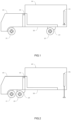
FIG.1 is a side view of a truck with lowerable bed in driving mode -
FIG.2 is a side view of a truck with lowerable bed during mode change. -
FIG.3 is a side view of a truck with lowerable bed in a loading mode. -
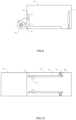
FIG.4 to FIG.6 are schematic views of the first embodiment. -
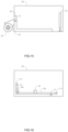
FIG.7 to FIG.12 are schematic views of the second embodiment. -
FIG.13 to FIG.18 are schematic views of the third embodiment. - Referring to
FIG.1 , a truck with lowerable bed to the first embodiment to the fifth embodiment of the present invention includes: afront axle 101, a driver'scab 102, arear axle 103, acargo container 104, asub-frame 105, afirst lifting device 201, asecond lifting device 202, and a first guidingdevice 203. - Referring to
FIG.1 , thefront axle 101 connects to the driver'scab 102; the driver'scab 102 connects to thesecond lifting device 202; thesecond lifting device 202 connects to thecargo container 104; thecargo container 104 connects to thefirst lifting device 201 and the first guidingdevice 203; the first guidingdevice 203 connects to thesub-frame 105; and thesub-frame 105 connects to therear axle 103. - Referring to
FIG.1 , thefront axle 101 is below the driver'scab 102; therear axle 103 is below thecargo container 104; and the driver'scab 102 is before thecargo container 104. - Referring to
FIG.1 and FIG.2 , when the truck is changed from driving mode to transition mode, thefirst lifting device 201 extend to maintain the rear height of thecargo container 104; thesub-frame 105 is moved forward on the horizontal part of the first guidingdevice 203; and therear axle 103 is moved from the position below thecargo container 104 to the position below the driver'scab 102. - Referring to
FIG.2 andFIG.3 , when the truck is changed from transition mode to loading mode, thefirst lifting device 201 controls the rear height of thecargo container 104 and thesecond lifting device 202 controls the front height of thecargo container 104 to allow thecargo container 104 to be moved downward from the first height to the second height; and thesub-frame 105 is moved upward on the vertical part of the first guidingdevice 203. - Referring to
FIG.3 andFIG.2 , when the truck is changed from the loading mode to transition mode, thefirst lifting device 201 controls the rear height of thecargo container 104 and thesecond lifting device 202 controls the front height of thecargo container 104 to allow thecargo container 104 to be moved upward from the second height to the first height; and thesub-frame 105 is move downward on the vertical part of the first guidingdevice 203. - Referring to
FIG.2 and FIG.1 , when the truck is changed from transition mode to driving mode, thesub-frame 105 is moved backward on the horizontal part of the first guidingdevice 203; therear axle 103 is moved from the position below the driver'scab 102 to the position below thecargo container 104; and thefirst lifting device 201 contract. - Referring to
FIG.4 , the rear axle movement to the first embodiment of the present invention includes an electric motor, a clutch, a first sub-frame driving element, and a second sub-frame driving element. - Referring to
FIG.4 , the horizontal part of the first guidingdevice 203 connects to the secondsub-frame driving element 302; the secondsub-frame driving element 302 connects to the firstsub-frame driving element 301; the firstsub-frame driving element 301 connects to thesub-frame 105 and the clutch; and the clutch connects to the electric motor. Wherein, the firstsub-frame driving element 301 can be a gear; the secondsub-frame driving element 302 can be a gear rack; and the firstsub-frame driving element 301 is meshing to the secondsub-frame driving element 302. - Referring to
FIG.4 , the firstsub-frame driving element 301 is on the horizontal part of the first guidingdevice 203. - Referring to
FIG.4 andFIG.5 , when the truck is changed from driving mode to transition mode, the clutch is connecting; the electric motor drives the firstsub-frame driving element 301 to move with respect to the secondsub-frame driving element 302; and the firstsub-frame driving element 301 is move forward on the horizontal part of the first guidingdevice 203. - Referring to
FIG.5 and FIG.6 , when the truck is changed from transition mode to loading mode, the clutch is disconnecting; thecargo container 104 is moved downward from the first height to the second height; the firstsub-frame driving element 301 disconnects to the second sub-frame driving element302; and the firstsub-frame driving element 301 is moved upward on the vertical part of the first guidingdevice 203. - Referring to
FIG.6 , the firstsub-frame driving element 301 is on the vertical part of the first guidingdevice 203. - Referring to
FIG.6 and FIG.5 , when the truck is changed from loading mode to transition mode, thecargo container 104 is moved upward from the second height to the first height; the firstsub-frame driving element 301 is moved downward on the vertical part of the first guiding 203; and the firstsub-frame driving element 301 connects to the secondsub-frame driving element 302. - Referring to
FIG.5 andFIG.4 , when the truck is changed from transition mode to driving mode, the clutch is connecting; the electric motor drives the firstsub-frame driving element 301 to move with respect to the secondsub-frame driving element 302; and the firstsub-frame driving element 301 is moved backward on the horizontal part of the first guidingdevice 203. - Referring to
FIG.7 , the rear axle movement to the second embodiment of the present invention includes a firstsub-frame driving element 301 and a secondsub-frame driving element 302. - Referring to
FIG.7 , the secondsub-frame driving element 302 connects to the horizontal part of the first guidingdevice 203; the secondsub-frame driving element 302 connects to the firstsub-frame driving element 301; and the firstsub-frame driving element 301 connects to thesub-frame 105. - Referring to
FIG.7 , the firstsub-frame driving element 301 is on the horizontal part of the first guidingdevice 203. - Referring to
FIG.7 and FIG.8 , when the truck is changed from driving mode to transition mode, the secondsub-frame driving element 302 is moved forward on the horizontal part of the first guidingdevice 203; and the firstsub-frame driving element 301 is moved forward on the horizontal part of the first guidingdevice 203. - Referring to
FIG.8 andFIG.9 , when the truck is changed from transition mode to loading mode, thecargo container 104 is moved downward from the first height to the second height; the firstsub-frame driving element 301 disconnects to the secondsub-frame driving element 302; and the firstsub-frame driving element 301 is moved upward on the vertical part of the first guidingdevice 203. - Referring to
FIG.9 , the firstsub-frame driving element 301 is on the vertical part of the first guidingdevice 203. - Referring to
FIG.9 andFIG.8 , when the truck is changed from loading mode to transition mode, thecargo container 104 is moved from the second height to the first height; the firstsub-frame driving element 301 is moved downward on the vertical part of the first guidingdevice 203; and the firstsub-frame driving element 301 connects to the secondsub-frame driving element 302. - Referring to
FIG.8 and FIG.7 , when the truck is changed from transition mode to driving mode, the secondsub-frame driving element 302 is moved backward on the horizontal part of the first guidingdevice 203; the firstsub-frame driving element 301 is moved backward on the horizontal part of the first guidingdevice 203. - Referring to
FIG.10 , the rear axle movement to the second embodiment of the present invention further includes a fixed end of thefirst chain 401, afirst chain 402, a first idler 403, and a second idler 404; wherein, the secondsub-frame driving element 302 connects to thefirst chain 402; thefirst chain 402 connects to the first fixed end of thefirst chain 401 through the first idler 403 and the second idler 404. - Referring to
FIG.10 andFIG.11 , when the truck is changed from driving mode to transition mode, the first fixed end of thefirst chain 401 is driven; the secondsub-frame driving element 302 is moved forward on the horizontal part of the first guidingdevice 203; and the firstsub-frame driving element 301 is moved forward on the horizontal part of the first guidingdevice 203. - Referring to
FIG.11 and FIG.12 , when the truck is changed from transition mode to loading mode, thecargo container 104 is moved downward from the first height to second height; the firstsub-frame driving element 301 disconnects to the secondsub-frame driving element 302; and the firstsub-frame driving element 301 is moved upward on the vertical part of the first guidingdevice 203. - Referring to
FIG.12 and FIG.11 , when the truck is changed from loading mode to transition mode, thecargo container 104 is moved upward from the second height to the first height; the firstsub-frame driving element 301 is moved downward on the vertical part of the first guidingdevice 203; and the firstsub-frame driving element 301 connects to the secondsub-frame driving element 302. - Referring to
FIG.11 andFIG.10 , when the truck is changed from transition mode to driving mode, the first fixed end of thefirst chain 401 is driven; the secondsub-frame driving element 302 is moved backward on the horizontal part of the first guidingdevice 203; and the firstsub-frame driving element 301 is moved backward on the horizontal part of the first guidingdevice 203. - Referring to
FIG.13 , the rear axle movement to the third embodiment of the present invention includes a firstsub-frame driving element 301. - Referring to
FIG.13 , the horizontal; part of the first guidingdevice 203 connects to the firstsub-frame driving element 301; and the firstsub-frame driving element 301 connects to thesub-frame 105. - Referring to
FIG.13 , the firstsub-frame driving element 301 is on the horizontal part of the first guidingdevice 203. - Referring to
FIG.13 and FIG.14 , when the truck is changed from driving mode to transition mode, the firstsub-frame driving element 301 is moved forward on the horizontal part of the first guidingdevice 203. - Referring to
FIG.14 andFIG.15 , when the truck is changed from transition mode to loading mode, thecargo container 104 is moved downward from the first height to the second height; and the firstsub-frame driving element 301 is moved upward on the vertical part of the first guidingdevice 203. - Referring to
FIG.15 , the firstsub-frame driving element 301 is on the vertical part of the first guidingdevice 203. - Referring to
FIG.15 andFIG.14 , when the truck is changed from loading mode to transition mode, thecargo container 104 is moved upward from the second height to the first height; and the firstsub-frame driving element 301 is moved downward on the vertical part of the first guidingdevice 203. - Referring to
FIG.14 and FIG.13 , when the truck is changed from transition mode to driving mode, the firstsub-frame driving element 301 is moved backward on the horizontal part of the first guidingdevice 203. - Referring to
FIG.16 , the rear axle movement to the third embodiment of the present invention further includes a fixed end of thefirst chain 401, afirst chain 402, afirst idler 411, asecond idler 412, athird idler 413 and afourth idler 414. Wherein, the firstsub-frame driving element 301 connects to thefirst chain 402; thefirst chain 402 connects to the first fixed end of thefirst chain 401 through thefirst idler 411, thesecond idler 412, thethird idler 413 and thefourth idler 414. - Referring to
FIG.16 andFIG.17 , when the truck is changed from driving mode to transition mode, the first fixed end of thefirst chain 401 is driven; the firstsub-frame driving element 301 is moved forward on the horizontal part of the first guidingdevice 203. - Referring to
FIG.17 and FIG.18 , when the truck is changed from transition mode to loading mode, thecargo container 104 is moved downward from the first height to the second height; the firstsub-frame driving element 301 is moved upward on the vertical part of the first guidingdevice 203; the first fixed end of thefirst chain 401 winds thefirst chain 402 through thethird idler 413 and thefourth idler 414; and the first fixed end of thefirst chain 401 unwinds thefirst chain 402 through thefirst idler 411 and thesecond idler 412. - Referring to
FIG.18 and FIG.17 , when the truck is changed from loading mode to transition mode, thecargo container 104 is moved upward from the second height to the first height; the firstsub-frame driving element 301 is moved downward on the vertical part of thefirst guiding device 203; the first fixed end of thefirst chain 401 unwinds thefirst chain 402 through thethird idler 413 and thefourth idler 414; and the first fixed end of thefirst chain 401 winds thefirst chain 402 through thefirst idler 411 and thesecond idler 412. - Referring to
FIG.17 andFIG.16 , when the truck is changed from transition mode to driving mode, the first fixed end of thefirst chain 401 is driven; and the firstsub-frame driving element 301 is moved backward on the horizontal part of thefirst guiding device 203. - The
rear axle 103 to the first embodiment to the third embodiment can be independent axle or dependent axle. - The
cargo container 104 to the first embodiment to the third embodiment can be hard-top container or platform. - Suspension part such as spring or shock absorber to the first embodiment to the third embodiment can be placed between the
sub-frame 105 and therear axle 103. - Transmission part such as transmission axle or differential to the first embodiment to the third embodiment can be placed between the
sub-frame 105 and therear axle 103. - The horizontal part of the
first guiding device 203 to the first embodiment to the third embodiment allows thesub-frame 105 to move longitudinally with respect to thecargo container 104. - The vertical part of the
first guiding device 203 to the first embodiment to the third embodiment allows thesub-frame 105 to move vertically with respect to thecargo container 104. - The horizontal part of the
first guiding device 203 to the first embodiment to the third embodiment can limit the distance between the firstsub-frame driving element 301 and the secondsub-frame driving element 302. - The second height to the first embodiment to the third embodiment can be ground.
- The electric motor to the first embodiment can drive rear axle.
- The electric motor to the first embodiment can connects to the first
sub-frame driving element 301. - The first fixed end of the
first chain 401 and thefirst chain 402 to the second embodiment to the third embodiment can be an transmission assembly of a first fixed of the first cable and a first cable, or a first fixed of the first belt and a belt. - The first fixed end of the
first chain 401 to the second embodiment to the third embodiment can be a linear actuator. - The first
sub-frame driving element 301 to the second embodiment to the third embodiment can further includes a connecting device, which can connects or disconnects to the firstsub-frame driving element 301 and the secondsub-frame driving element 302. - The second
sub-frame driving element 302 to the second embodiment to the third embodiment can further includes a connecting device, which can connects or disconnects to the firstsub-frame driving element 301 and the secondsub-frame driving element 302. - The second fixed end of the first chain to the second embodiment can be further included, and the
first chain 402 can connects to the first fixed end of thefirst chain 401 and the second fixed end of the first chain. - The second
sub-frame driving element 302 to the third embodiment can connect to the firstsub-frame driving element 301 and thefirst guiding device 203. - The second fixed end of the first chain to the third embodiment can be further included, and the
first chain 402 can connects to the first fixed end of thefirst chain 401 and the second fixed end of the first chain.
Claims (11)
- A rear axle movement device for a truck with a lowerable bed, wherein the truck with the lowerable bed includes:a front axle, a driver's cab, a rear axle, a cargo container, a sub-frame, a first lifting device, a second lifting device, and a first guiding device;wherein said first guiding device includes a horizontal part of said first guiding device and a vertical part of said first guiding device;wherein said front axle connects to said driver's cab;wherein said driver's cab connects said second lifting device;wherein said second lifting device connects to said cargo container;wherein said cargo container connects to said first lifting device and said first guiding device;wherein, in a driving mode, said front axle is below said driver's cab and said rear axle is below said cargo container;wherein, in a loading mode, said front axle is below said driver's cab and said rear axle is below said driver's cab;wherein said rear axle movement device comprising: a first sub-frame driving element;wherein said first guiding device connects to said first sub-frame driving element;wherein said first sub-frame driving element connects to said sub-frame;wherein said first sub-frame driving element is in said horizontal part of said first guiding device in the driving mode;wherein said first sub-frame driving element is in said vertical part of said first guiding device in the loading mode.
- The rear axle movement device as claimed in claim 1, further including:a first chain and a first fixed end of the first chain;wherein said first fixed end of the first chain connects to said first chain;wherein said first chain connects to said first sub-frame driving element.
- The rear axle movement device as claimed in claim 1, further including:a first cable and a first fixed end of the first cable;wherein said first fixed end of the first cable connects to said first cable;wherein said first cable connects to said first sub-frame driving element.
- The rear axle movement device as claimed in claim 1, further including:a first belt and a first fixed end of the first belt;wherein said first fixed end of the first belt connects to said first belt;wherein said first belt connects to said first sub-frame driving element.
- The rear axle movement device as claimed in claim 1, further including:a second sub-frame driving element;wherein said second sub-frame driving element connects to said first guiding device andsaid first sub-frame driving element.
- The rear axle movement device as claimed in claim 1 or 5, further including:an electric motor;wherein said electric motor connects to said first sub-frame driving element.
- The rear axle movement device as claimed in claim 6, further including:a clutch;wherein said clutch connects to said electric motor and said first sub-frame driving element.
- The rear axle movement device as claimed in claim 5, further including:a first chain and a first fixed end of the first chain;wherein said first fixed end of the first chain connects to said first chain;wherein said first chain connects to said second sub-frame driving element.
- The rear axle movement device as claimed in claim 5, further including:a first cable and a first fixed end of the first cable;wherein said first fixed end of the first cable connects to said first cable;wherein said first cable connects to said second sub-frame driving element.
- The rear axle movement device as claimed in claim 5, further including:a first belt and a first fixed end of the first belt;wherein said first fixed end of the first belt connects to said first belt;wherein said first belt connects to said second sub-frame driving element.
- The rear axle movement device as claimed in claim 2 or 8, further comprising:a second fixed end of the first chain;wherein said first chain connects to said second fixed end of the first chain.
Applications Claiming Priority (1)
| Application Number | Priority Date | Filing Date | Title |
|---|---|---|---|
| TW111103229A TW202330318A (en) | 2022-01-24 | 2022-01-24 | Rear Axle Movement Device for Truck with Lowerable Bed |
Publications (1)
| Publication Number | Publication Date |
|---|---|
| EP4223587A1 true EP4223587A1 (en) | 2023-08-09 |
Family
ID=85017683
Family Applications (1)
| Application Number | Title | Priority Date | Filing Date |
|---|---|---|---|
| EP23152326.7A Withdrawn EP4223587A1 (en) | 2022-01-24 | 2023-01-19 | Rear axle movement device for truck with lowerable bed |
Country Status (8)
| Country | Link |
|---|---|
| US (1) | US20230234541A1 (en) |
| EP (1) | EP4223587A1 (en) |
| JP (1) | JP2023107738A (en) |
| KR (1) | KR20230115238A (en) |
| CN (1) | CN116476717A (en) |
| AU (1) | AU2023200207A1 (en) |
| CA (1) | CA3186218A1 (en) |
| TW (1) | TW202330318A (en) |
Citations (5)
| Publication number | Priority date | Publication date | Assignee | Title |
|---|---|---|---|---|
| US4026429A (en) * | 1973-10-29 | 1977-05-31 | Rumell James A | Method of unloading container from transport vehicle |
| DE4333631A1 (en) * | 1993-10-02 | 1995-04-06 | Zikun Fahrzeugbau Gmbh | Transportation vehicle |
| CH703885A2 (en) * | 2010-09-16 | 2012-03-30 | Peter Gallersdoerfer | Vehicle, particularly two-axle truck, has rear axle that is either connected with hatch door or with swivel device, where hatch door or swivel device swivels around swivel axis |
| US20130285348A1 (en) * | 2011-01-17 | 2013-10-31 | Volvo Technology Of America, Inc. | Adjustable towing system and method |
| EP3702211A1 (en) * | 2018-06-06 | 2020-09-02 | Valsch Dynamic Mechatronics Ltd. | Truck with lowerable bed |
-
2022
- 2022-01-24 TW TW111103229A patent/TW202330318A/en unknown
- 2022-12-20 JP JP2022202806A patent/JP2023107738A/en active Pending
-
2023
- 2023-01-12 KR KR1020230004514A patent/KR20230115238A/en not_active Ceased
- 2023-01-12 CA CA3186218A patent/CA3186218A1/en active Pending
- 2023-01-13 CN CN202310064429.6A patent/CN116476717A/en active Pending
- 2023-01-16 AU AU2023200207A patent/AU2023200207A1/en not_active Abandoned
- 2023-01-17 US US18/097,504 patent/US20230234541A1/en not_active Abandoned
- 2023-01-19 EP EP23152326.7A patent/EP4223587A1/en not_active Withdrawn
Patent Citations (5)
| Publication number | Priority date | Publication date | Assignee | Title |
|---|---|---|---|---|
| US4026429A (en) * | 1973-10-29 | 1977-05-31 | Rumell James A | Method of unloading container from transport vehicle |
| DE4333631A1 (en) * | 1993-10-02 | 1995-04-06 | Zikun Fahrzeugbau Gmbh | Transportation vehicle |
| CH703885A2 (en) * | 2010-09-16 | 2012-03-30 | Peter Gallersdoerfer | Vehicle, particularly two-axle truck, has rear axle that is either connected with hatch door or with swivel device, where hatch door or swivel device swivels around swivel axis |
| US20130285348A1 (en) * | 2011-01-17 | 2013-10-31 | Volvo Technology Of America, Inc. | Adjustable towing system and method |
| EP3702211A1 (en) * | 2018-06-06 | 2020-09-02 | Valsch Dynamic Mechatronics Ltd. | Truck with lowerable bed |
Also Published As
| Publication number | Publication date |
|---|---|
| AU2023200207A1 (en) | 2023-08-10 |
| KR20230115238A (en) | 2023-08-02 |
| CN116476717A (en) | 2023-07-25 |
| JP2023107738A (en) | 2023-08-03 |
| CA3186218A1 (en) | 2023-07-24 |
| TW202330318A (en) | 2023-08-01 |
| US20230234541A1 (en) | 2023-07-27 |
Similar Documents
| Publication | Publication Date | Title |
|---|---|---|
| TWI706875B (en) | Truck with lowerable bed | |
| CA2428426C (en) | Low load floor motor vehicle | |
| CA2489856A1 (en) | Low load floor motor vehicle | |
| CN111923761B (en) | Automobile lifting type charging system | |
| EP4223587A1 (en) | Rear axle movement device for truck with lowerable bed | |
| CN209506120U (en) | A kind of unmanned helicopter ground trailer | |
| EP4163152A1 (en) | Rear axle movement device for truck with lowerable bed | |
| CN212831642U (en) | Loading device of van | |
| CN219668484U (en) | Flat plate regulation type aircraft tractor | |
| CN214732133U (en) | Novel AGV dolly | |
| CN205524689U (en) | Storage battery car | |
| CN114735621A (en) | Automatic navigation side direction fork truck | |
| CN218320619U (en) | Remote control type telescopic arm forklift convenient for container transportation | |
| CN209778195U (en) | Order-picking vehicle | |
| GB2317598A (en) | Load-carrying vehicle | |
| CN204400558U (en) | The mounting structure of the drive system of heavy duty transport trolley | |
| CN220053637U (en) | Intelligent storage transfer trolley for aircraft nacelle | |
| CN218431493U (en) | AGV and AGV system | |
| CN217535342U (en) | Special fork truck that turns to that slides in chicken farm | |
| CN216272963U (en) | Balanced AGV heavy stacking vehicle body with brand new structure | |
| CN217627431U (en) | Height-adjustable forklift frame | |
| CN120738955A (en) | Rail conveyor intelligent protection equipment | |
| KR20050108539A (en) | Driving gear which the saftyload it loads | |
| US1919325A (en) | Lift body for motor vehicles | |
| CN121849547A (en) | A type of traction shuttle |
Legal Events
| Date | Code | Title | Description |
|---|---|---|---|
| PUAI | Public reference made under article 153(3) epc to a published international application that has entered the european phase |
Free format text: ORIGINAL CODE: 0009012 |
|
| STAA | Information on the status of an ep patent application or granted ep patent |
Free format text: STATUS: REQUEST FOR EXAMINATION WAS MADE |
|
| 17P | Request for examination filed |
Effective date: 20230119 |
|
| AK | Designated contracting states |
Kind code of ref document: A1 Designated state(s): AL AT BE BG CH CY CZ DE DK EE ES FI FR GB GR HR HU IE IS IT LI LT LU LV MC ME MK MT NL NO PL PT RO RS SE SI SK SM TR |
|
| STAA | Information on the status of an ep patent application or granted ep patent |
Free format text: STATUS: THE APPLICATION IS DEEMED TO BE WITHDRAWN |
|
| 18D | Application deemed to be withdrawn |
Effective date: 20240210 |