EP4220002A1 - Pressure vessel - Google Patents
Pressure vessel Download PDFInfo
- Publication number
- EP4220002A1 EP4220002A1 EP23156246.3A EP23156246A EP4220002A1 EP 4220002 A1 EP4220002 A1 EP 4220002A1 EP 23156246 A EP23156246 A EP 23156246A EP 4220002 A1 EP4220002 A1 EP 4220002A1
- Authority
- EP
- European Patent Office
- Prior art keywords
- tank liner
- pressure vessel
- segments
- permeation barrier
- use according
- Prior art date
- Legal status (The legal status is an assumption and is not a legal conclusion. Google has not performed a legal analysis and makes no representation as to the accuracy of the status listed.)
- Pending
Links
- VNWKTOKETHGBQD-UHFFFAOYSA-N methane Chemical compound C VNWKTOKETHGBQD-UHFFFAOYSA-N 0.000 claims abstract description 63
- 229920000049 Carbon (fiber) Polymers 0.000 claims abstract description 31
- 239000004917 carbon fiber Substances 0.000 claims abstract description 31
- 239000002131 composite material Substances 0.000 claims abstract description 9
- 230000004888 barrier function Effects 0.000 claims description 26
- 239000000463 material Substances 0.000 claims description 11
- 229910052751 metal Inorganic materials 0.000 claims description 11
- 239000002184 metal Substances 0.000 claims description 11
- 239000000654 additive Substances 0.000 claims description 10
- 239000002105 nanoparticle Substances 0.000 claims description 8
- 230000000996 additive effect Effects 0.000 claims description 6
- OKTJSMMVPCPJKN-UHFFFAOYSA-N Carbon Chemical compound [C] OKTJSMMVPCPJKN-UHFFFAOYSA-N 0.000 claims description 4
- 229920002430 Fibre-reinforced plastic Polymers 0.000 claims description 4
- 239000002041 carbon nanotube Substances 0.000 claims description 4
- 229910021393 carbon nanotube Inorganic materials 0.000 claims description 4
- 239000004927 clay Substances 0.000 claims description 4
- 239000011151 fibre-reinforced plastic Substances 0.000 claims description 4
- 238000004519 manufacturing process Methods 0.000 claims description 4
- 239000003365 glass fiber Substances 0.000 claims description 3
- 239000004814 polyurethane Substances 0.000 claims description 3
- 239000000853 adhesive Substances 0.000 claims description 2
- 230000001070 adhesive effect Effects 0.000 claims description 2
- 239000011152 fibreglass Substances 0.000 claims description 2
- 239000000945 filler Substances 0.000 claims description 2
- 229920000162 poly(ureaurethane) Polymers 0.000 claims description 2
- 229920000642 polymer Polymers 0.000 claims description 2
- 229920002635 polyurethane Polymers 0.000 claims description 2
- 239000002071 nanotube Substances 0.000 claims 1
- 239000000835 fiber Substances 0.000 description 15
- 239000004593 Epoxy Substances 0.000 description 8
- 229920005989 resin Polymers 0.000 description 8
- 239000011347 resin Substances 0.000 description 8
- 239000007789 gas Substances 0.000 description 4
- 229910052782 aluminium Inorganic materials 0.000 description 3
- XAGFODPZIPBFFR-UHFFFAOYSA-N aluminium Chemical group [Al] XAGFODPZIPBFFR-UHFFFAOYSA-N 0.000 description 3
- 230000008901 benefit Effects 0.000 description 3
- 239000000446 fuel Substances 0.000 description 3
- 230000001681 protective effect Effects 0.000 description 3
- 238000003860 storage Methods 0.000 description 3
- XKRFYHLGVUSROY-UHFFFAOYSA-N Argon Chemical compound [Ar] XKRFYHLGVUSROY-UHFFFAOYSA-N 0.000 description 2
- 229920002396 Polyurea Polymers 0.000 description 2
- ATUOYWHBWRKTHZ-UHFFFAOYSA-N Propane Chemical compound CCC ATUOYWHBWRKTHZ-UHFFFAOYSA-N 0.000 description 2
- 239000007788 liquid Substances 0.000 description 2
- 239000011159 matrix material Substances 0.000 description 2
- -1 polypropylene Polymers 0.000 description 2
- XQUPVDVFXZDTLT-UHFFFAOYSA-N 1-[4-[[4-(2,5-dioxopyrrol-1-yl)phenyl]methyl]phenyl]pyrrole-2,5-dione Chemical compound O=C1C=CC(=O)N1C(C=C1)=CC=C1CC1=CC=C(N2C(C=CC2=O)=O)C=C1 XQUPVDVFXZDTLT-UHFFFAOYSA-N 0.000 description 1
- CMLFRMDBDNHMRA-UHFFFAOYSA-N 2h-1,2-benzoxazine Chemical compound C1=CC=C2C=CNOC2=C1 CMLFRMDBDNHMRA-UHFFFAOYSA-N 0.000 description 1
- 229920002748 Basalt fiber Polymers 0.000 description 1
- 235000011777 Corchorus aestuans Nutrition 0.000 description 1
- 240000000491 Corchorus aestuans Species 0.000 description 1
- 235000010862 Corchorus capsularis Nutrition 0.000 description 1
- LFQSCWFLJHTTHZ-UHFFFAOYSA-N Ethanol Chemical compound CCO LFQSCWFLJHTTHZ-UHFFFAOYSA-N 0.000 description 1
- 235000015842 Hesperis Nutrition 0.000 description 1
- UFHFLCQGNIYNRP-UHFFFAOYSA-N Hydrogen Chemical compound [H][H] UFHFLCQGNIYNRP-UHFFFAOYSA-N 0.000 description 1
- 235000012633 Iberis amara Nutrition 0.000 description 1
- 239000004677 Nylon Substances 0.000 description 1
- 239000004698 Polyethylene Substances 0.000 description 1
- 239000004743 Polypropylene Substances 0.000 description 1
- 229910000831 Steel Inorganic materials 0.000 description 1
- 229920000508 Vectran Polymers 0.000 description 1
- 239000004979 Vectran Substances 0.000 description 1
- 229910052786 argon Inorganic materials 0.000 description 1
- 230000000712 assembly Effects 0.000 description 1
- 238000000429 assembly Methods 0.000 description 1
- 239000004918 carbon fiber reinforced polymer Substances 0.000 description 1
- 230000008859 change Effects 0.000 description 1
- 239000003795 chemical substances by application Substances 0.000 description 1
- 238000010276 construction Methods 0.000 description 1
- 238000009792 diffusion process Methods 0.000 description 1
- 125000003700 epoxy group Chemical group 0.000 description 1
- 239000004744 fabric Substances 0.000 description 1
- 238000009730 filament winding Methods 0.000 description 1
- 238000005242 forging Methods 0.000 description 1
- 239000001307 helium Substances 0.000 description 1
- 229910052734 helium Inorganic materials 0.000 description 1
- SWQJXJOGLNCZEY-UHFFFAOYSA-N helium atom Chemical compound [He] SWQJXJOGLNCZEY-UHFFFAOYSA-N 0.000 description 1
- 229920001903 high density polyethylene Polymers 0.000 description 1
- 239000004700 high-density polyethylene Substances 0.000 description 1
- 239000001257 hydrogen Substances 0.000 description 1
- 229910052739 hydrogen Inorganic materials 0.000 description 1
- 230000007246 mechanism Effects 0.000 description 1
- 239000000203 mixture Substances 0.000 description 1
- 239000003345 natural gas Substances 0.000 description 1
- 229920001778 nylon Polymers 0.000 description 1
- 229920003023 plastic Polymers 0.000 description 1
- 239000004033 plastic Substances 0.000 description 1
- 229920003192 poly(bis maleimide) Polymers 0.000 description 1
- 229920002577 polybenzoxazole Polymers 0.000 description 1
- 229920000647 polyepoxide Polymers 0.000 description 1
- 229920000573 polyethylene Polymers 0.000 description 1
- 229920001155 polypropylene Polymers 0.000 description 1
- 229920003226 polyurethane urea Polymers 0.000 description 1
- 239000001294 propane Substances 0.000 description 1
- 239000012812 sealant material Substances 0.000 description 1
- 239000010959 steel Substances 0.000 description 1
- 239000004753 textile Substances 0.000 description 1
- 150000003673 urethanes Chemical class 0.000 description 1
- 229920001567 vinyl ester resin Polymers 0.000 description 1
- 238000004804 winding Methods 0.000 description 1
Images


Classifications
-
- F—MECHANICAL ENGINEERING; LIGHTING; HEATING; WEAPONS; BLASTING
- F17—STORING OR DISTRIBUTING GASES OR LIQUIDS
- F17C—VESSELS FOR CONTAINING OR STORING COMPRESSED, LIQUEFIED OR SOLIDIFIED GASES; FIXED-CAPACITY GAS-HOLDERS; FILLING VESSELS WITH, OR DISCHARGING FROM VESSELS, COMPRESSED, LIQUEFIED, OR SOLIDIFIED GASES
- F17C1/00—Pressure vessels, e.g. gas cylinder, gas tank, replaceable cartridge
- F17C1/02—Pressure vessels, e.g. gas cylinder, gas tank, replaceable cartridge involving reinforcing arrangements
- F17C1/04—Protecting sheathings
- F17C1/06—Protecting sheathings built-up from wound-on bands or filamentary material, e.g. wires
-
- F—MECHANICAL ENGINEERING; LIGHTING; HEATING; WEAPONS; BLASTING
- F17—STORING OR DISTRIBUTING GASES OR LIQUIDS
- F17C—VESSELS FOR CONTAINING OR STORING COMPRESSED, LIQUEFIED OR SOLIDIFIED GASES; FIXED-CAPACITY GAS-HOLDERS; FILLING VESSELS WITH, OR DISCHARGING FROM VESSELS, COMPRESSED, LIQUEFIED, OR SOLIDIFIED GASES
- F17C1/00—Pressure vessels, e.g. gas cylinder, gas tank, replaceable cartridge
- F17C1/16—Pressure vessels, e.g. gas cylinder, gas tank, replaceable cartridge constructed of plastics materials
-
- F—MECHANICAL ENGINEERING; LIGHTING; HEATING; WEAPONS; BLASTING
- F17—STORING OR DISTRIBUTING GASES OR LIQUIDS
- F17C—VESSELS FOR CONTAINING OR STORING COMPRESSED, LIQUEFIED OR SOLIDIFIED GASES; FIXED-CAPACITY GAS-HOLDERS; FILLING VESSELS WITH, OR DISCHARGING FROM VESSELS, COMPRESSED, LIQUEFIED, OR SOLIDIFIED GASES
- F17C2201/00—Vessel construction, in particular geometry, arrangement or size
- F17C2201/01—Shape
- F17C2201/0104—Shape cylindrical
- F17C2201/0109—Shape cylindrical with exteriorly curved end-piece
-
- F—MECHANICAL ENGINEERING; LIGHTING; HEATING; WEAPONS; BLASTING
- F17—STORING OR DISTRIBUTING GASES OR LIQUIDS
- F17C—VESSELS FOR CONTAINING OR STORING COMPRESSED, LIQUEFIED OR SOLIDIFIED GASES; FIXED-CAPACITY GAS-HOLDERS; FILLING VESSELS WITH, OR DISCHARGING FROM VESSELS, COMPRESSED, LIQUEFIED, OR SOLIDIFIED GASES
- F17C2201/00—Vessel construction, in particular geometry, arrangement or size
- F17C2201/01—Shape
- F17C2201/0128—Shape spherical or elliptical
-
- F—MECHANICAL ENGINEERING; LIGHTING; HEATING; WEAPONS; BLASTING
- F17—STORING OR DISTRIBUTING GASES OR LIQUIDS
- F17C—VESSELS FOR CONTAINING OR STORING COMPRESSED, LIQUEFIED OR SOLIDIFIED GASES; FIXED-CAPACITY GAS-HOLDERS; FILLING VESSELS WITH, OR DISCHARGING FROM VESSELS, COMPRESSED, LIQUEFIED, OR SOLIDIFIED GASES
- F17C2201/00—Vessel construction, in particular geometry, arrangement or size
- F17C2201/01—Shape
- F17C2201/0142—Shape conical
-
- F—MECHANICAL ENGINEERING; LIGHTING; HEATING; WEAPONS; BLASTING
- F17—STORING OR DISTRIBUTING GASES OR LIQUIDS
- F17C—VESSELS FOR CONTAINING OR STORING COMPRESSED, LIQUEFIED OR SOLIDIFIED GASES; FIXED-CAPACITY GAS-HOLDERS; FILLING VESSELS WITH, OR DISCHARGING FROM VESSELS, COMPRESSED, LIQUEFIED, OR SOLIDIFIED GASES
- F17C2201/00—Vessel construction, in particular geometry, arrangement or size
- F17C2201/05—Size
- F17C2201/054—Size medium (>1 m3)
-
- F—MECHANICAL ENGINEERING; LIGHTING; HEATING; WEAPONS; BLASTING
- F17—STORING OR DISTRIBUTING GASES OR LIQUIDS
- F17C—VESSELS FOR CONTAINING OR STORING COMPRESSED, LIQUEFIED OR SOLIDIFIED GASES; FIXED-CAPACITY GAS-HOLDERS; FILLING VESSELS WITH, OR DISCHARGING FROM VESSELS, COMPRESSED, LIQUEFIED, OR SOLIDIFIED GASES
- F17C2203/00—Vessel construction, in particular walls or details thereof
- F17C2203/06—Materials for walls or layers thereof; Properties or structures of walls or their materials
- F17C2203/0602—Wall structures; Special features thereof
- F17C2203/0604—Liners
-
- F—MECHANICAL ENGINEERING; LIGHTING; HEATING; WEAPONS; BLASTING
- F17—STORING OR DISTRIBUTING GASES OR LIQUIDS
- F17C—VESSELS FOR CONTAINING OR STORING COMPRESSED, LIQUEFIED OR SOLIDIFIED GASES; FIXED-CAPACITY GAS-HOLDERS; FILLING VESSELS WITH, OR DISCHARGING FROM VESSELS, COMPRESSED, LIQUEFIED, OR SOLIDIFIED GASES
- F17C2203/00—Vessel construction, in particular walls or details thereof
- F17C2203/06—Materials for walls or layers thereof; Properties or structures of walls or their materials
- F17C2203/0602—Wall structures; Special features thereof
- F17C2203/0609—Straps, bands or ribbons
-
- F—MECHANICAL ENGINEERING; LIGHTING; HEATING; WEAPONS; BLASTING
- F17—STORING OR DISTRIBUTING GASES OR LIQUIDS
- F17C—VESSELS FOR CONTAINING OR STORING COMPRESSED, LIQUEFIED OR SOLIDIFIED GASES; FIXED-CAPACITY GAS-HOLDERS; FILLING VESSELS WITH, OR DISCHARGING FROM VESSELS, COMPRESSED, LIQUEFIED, OR SOLIDIFIED GASES
- F17C2203/00—Vessel construction, in particular walls or details thereof
- F17C2203/06—Materials for walls or layers thereof; Properties or structures of walls or their materials
- F17C2203/0602—Wall structures; Special features thereof
- F17C2203/0612—Wall structures
- F17C2203/0614—Single wall
- F17C2203/0619—Single wall with two layers
-
- F—MECHANICAL ENGINEERING; LIGHTING; HEATING; WEAPONS; BLASTING
- F17—STORING OR DISTRIBUTING GASES OR LIQUIDS
- F17C—VESSELS FOR CONTAINING OR STORING COMPRESSED, LIQUEFIED OR SOLIDIFIED GASES; FIXED-CAPACITY GAS-HOLDERS; FILLING VESSELS WITH, OR DISCHARGING FROM VESSELS, COMPRESSED, LIQUEFIED, OR SOLIDIFIED GASES
- F17C2203/00—Vessel construction, in particular walls or details thereof
- F17C2203/06—Materials for walls or layers thereof; Properties or structures of walls or their materials
- F17C2203/0602—Wall structures; Special features thereof
- F17C2203/0612—Wall structures
- F17C2203/0614—Single wall
- F17C2203/0621—Single wall with three layers
-
- F—MECHANICAL ENGINEERING; LIGHTING; HEATING; WEAPONS; BLASTING
- F17—STORING OR DISTRIBUTING GASES OR LIQUIDS
- F17C—VESSELS FOR CONTAINING OR STORING COMPRESSED, LIQUEFIED OR SOLIDIFIED GASES; FIXED-CAPACITY GAS-HOLDERS; FILLING VESSELS WITH, OR DISCHARGING FROM VESSELS, COMPRESSED, LIQUEFIED, OR SOLIDIFIED GASES
- F17C2203/00—Vessel construction, in particular walls or details thereof
- F17C2203/06—Materials for walls or layers thereof; Properties or structures of walls or their materials
- F17C2203/0602—Wall structures; Special features thereof
- F17C2203/0612—Wall structures
- F17C2203/0614—Single wall
- F17C2203/0624—Single wall with four or more layers
-
- F—MECHANICAL ENGINEERING; LIGHTING; HEATING; WEAPONS; BLASTING
- F17—STORING OR DISTRIBUTING GASES OR LIQUIDS
- F17C—VESSELS FOR CONTAINING OR STORING COMPRESSED, LIQUEFIED OR SOLIDIFIED GASES; FIXED-CAPACITY GAS-HOLDERS; FILLING VESSELS WITH, OR DISCHARGING FROM VESSELS, COMPRESSED, LIQUEFIED, OR SOLIDIFIED GASES
- F17C2203/00—Vessel construction, in particular walls or details thereof
- F17C2203/06—Materials for walls or layers thereof; Properties or structures of walls or their materials
- F17C2203/0634—Materials for walls or layers thereof
- F17C2203/0658—Synthetics
- F17C2203/066—Plastics
-
- F—MECHANICAL ENGINEERING; LIGHTING; HEATING; WEAPONS; BLASTING
- F17—STORING OR DISTRIBUTING GASES OR LIQUIDS
- F17C—VESSELS FOR CONTAINING OR STORING COMPRESSED, LIQUEFIED OR SOLIDIFIED GASES; FIXED-CAPACITY GAS-HOLDERS; FILLING VESSELS WITH, OR DISCHARGING FROM VESSELS, COMPRESSED, LIQUEFIED, OR SOLIDIFIED GASES
- F17C2203/00—Vessel construction, in particular walls or details thereof
- F17C2203/06—Materials for walls or layers thereof; Properties or structures of walls or their materials
- F17C2203/0634—Materials for walls or layers thereof
- F17C2203/0658—Synthetics
- F17C2203/0663—Synthetics in form of fibers or filaments
- F17C2203/0665—Synthetics in form of fibers or filaments radially wound
-
- F—MECHANICAL ENGINEERING; LIGHTING; HEATING; WEAPONS; BLASTING
- F17—STORING OR DISTRIBUTING GASES OR LIQUIDS
- F17C—VESSELS FOR CONTAINING OR STORING COMPRESSED, LIQUEFIED OR SOLIDIFIED GASES; FIXED-CAPACITY GAS-HOLDERS; FILLING VESSELS WITH, OR DISCHARGING FROM VESSELS, COMPRESSED, LIQUEFIED, OR SOLIDIFIED GASES
- F17C2203/00—Vessel construction, in particular walls or details thereof
- F17C2203/06—Materials for walls or layers thereof; Properties or structures of walls or their materials
- F17C2203/0634—Materials for walls or layers thereof
- F17C2203/0658—Synthetics
- F17C2203/0663—Synthetics in form of fibers or filaments
- F17C2203/0668—Synthetics in form of fibers or filaments axially wound
-
- F—MECHANICAL ENGINEERING; LIGHTING; HEATING; WEAPONS; BLASTING
- F17—STORING OR DISTRIBUTING GASES OR LIQUIDS
- F17C—VESSELS FOR CONTAINING OR STORING COMPRESSED, LIQUEFIED OR SOLIDIFIED GASES; FIXED-CAPACITY GAS-HOLDERS; FILLING VESSELS WITH, OR DISCHARGING FROM VESSELS, COMPRESSED, LIQUEFIED, OR SOLIDIFIED GASES
- F17C2203/00—Vessel construction, in particular walls or details thereof
- F17C2203/06—Materials for walls or layers thereof; Properties or structures of walls or their materials
- F17C2203/0634—Materials for walls or layers thereof
- F17C2203/0658—Synthetics
- F17C2203/0663—Synthetics in form of fibers or filaments
- F17C2203/067—Synthetics in form of fibers or filaments helically wound
-
- F—MECHANICAL ENGINEERING; LIGHTING; HEATING; WEAPONS; BLASTING
- F17—STORING OR DISTRIBUTING GASES OR LIQUIDS
- F17C—VESSELS FOR CONTAINING OR STORING COMPRESSED, LIQUEFIED OR SOLIDIFIED GASES; FIXED-CAPACITY GAS-HOLDERS; FILLING VESSELS WITH, OR DISCHARGING FROM VESSELS, COMPRESSED, LIQUEFIED, OR SOLIDIFIED GASES
- F17C2203/00—Vessel construction, in particular walls or details thereof
- F17C2203/06—Materials for walls or layers thereof; Properties or structures of walls or their materials
- F17C2203/068—Special properties of materials for vessel walls
- F17C2203/0697—Special properties of materials for vessel walls comprising nanoparticles
-
- F—MECHANICAL ENGINEERING; LIGHTING; HEATING; WEAPONS; BLASTING
- F17—STORING OR DISTRIBUTING GASES OR LIQUIDS
- F17C—VESSELS FOR CONTAINING OR STORING COMPRESSED, LIQUEFIED OR SOLIDIFIED GASES; FIXED-CAPACITY GAS-HOLDERS; FILLING VESSELS WITH, OR DISCHARGING FROM VESSELS, COMPRESSED, LIQUEFIED, OR SOLIDIFIED GASES
- F17C2205/00—Vessel construction, in particular mounting arrangements, attachments or identifications means
- F17C2205/01—Mounting arrangements
- F17C2205/0103—Exterior arrangements
- F17C2205/0107—Frames
-
- F—MECHANICAL ENGINEERING; LIGHTING; HEATING; WEAPONS; BLASTING
- F17—STORING OR DISTRIBUTING GASES OR LIQUIDS
- F17C—VESSELS FOR CONTAINING OR STORING COMPRESSED, LIQUEFIED OR SOLIDIFIED GASES; FIXED-CAPACITY GAS-HOLDERS; FILLING VESSELS WITH, OR DISCHARGING FROM VESSELS, COMPRESSED, LIQUEFIED, OR SOLIDIFIED GASES
- F17C2205/00—Vessel construction, in particular mounting arrangements, attachments or identifications means
- F17C2205/01—Mounting arrangements
- F17C2205/0123—Mounting arrangements characterised by number of vessels
- F17C2205/013—Two or more vessels
-
- F—MECHANICAL ENGINEERING; LIGHTING; HEATING; WEAPONS; BLASTING
- F17—STORING OR DISTRIBUTING GASES OR LIQUIDS
- F17C—VESSELS FOR CONTAINING OR STORING COMPRESSED, LIQUEFIED OR SOLIDIFIED GASES; FIXED-CAPACITY GAS-HOLDERS; FILLING VESSELS WITH, OR DISCHARGING FROM VESSELS, COMPRESSED, LIQUEFIED, OR SOLIDIFIED GASES
- F17C2205/00—Vessel construction, in particular mounting arrangements, attachments or identifications means
- F17C2205/03—Fluid connections, filters, valves, closure means or other attachments
- F17C2205/0302—Fittings, valves, filters, or components in connection with the gas storage device
- F17C2205/0305—Bosses, e.g. boss collars
-
- F—MECHANICAL ENGINEERING; LIGHTING; HEATING; WEAPONS; BLASTING
- F17—STORING OR DISTRIBUTING GASES OR LIQUIDS
- F17C—VESSELS FOR CONTAINING OR STORING COMPRESSED, LIQUEFIED OR SOLIDIFIED GASES; FIXED-CAPACITY GAS-HOLDERS; FILLING VESSELS WITH, OR DISCHARGING FROM VESSELS, COMPRESSED, LIQUEFIED, OR SOLIDIFIED GASES
- F17C2209/00—Vessel construction, in particular methods of manufacturing
- F17C2209/21—Shaping processes
- F17C2209/2109—Moulding
-
- F—MECHANICAL ENGINEERING; LIGHTING; HEATING; WEAPONS; BLASTING
- F17—STORING OR DISTRIBUTING GASES OR LIQUIDS
- F17C—VESSELS FOR CONTAINING OR STORING COMPRESSED, LIQUEFIED OR SOLIDIFIED GASES; FIXED-CAPACITY GAS-HOLDERS; FILLING VESSELS WITH, OR DISCHARGING FROM VESSELS, COMPRESSED, LIQUEFIED, OR SOLIDIFIED GASES
- F17C2209/00—Vessel construction, in particular methods of manufacturing
- F17C2209/21—Shaping processes
- F17C2209/2154—Winding
- F17C2209/2163—Winding with a mandrel
-
- F—MECHANICAL ENGINEERING; LIGHTING; HEATING; WEAPONS; BLASTING
- F17—STORING OR DISTRIBUTING GASES OR LIQUIDS
- F17C—VESSELS FOR CONTAINING OR STORING COMPRESSED, LIQUEFIED OR SOLIDIFIED GASES; FIXED-CAPACITY GAS-HOLDERS; FILLING VESSELS WITH, OR DISCHARGING FROM VESSELS, COMPRESSED, LIQUEFIED, OR SOLIDIFIED GASES
- F17C2209/00—Vessel construction, in particular methods of manufacturing
- F17C2209/22—Assembling processes
- F17C2209/227—Assembling processes by adhesive means
-
- F—MECHANICAL ENGINEERING; LIGHTING; HEATING; WEAPONS; BLASTING
- F17—STORING OR DISTRIBUTING GASES OR LIQUIDS
- F17C—VESSELS FOR CONTAINING OR STORING COMPRESSED, LIQUEFIED OR SOLIDIFIED GASES; FIXED-CAPACITY GAS-HOLDERS; FILLING VESSELS WITH, OR DISCHARGING FROM VESSELS, COMPRESSED, LIQUEFIED, OR SOLIDIFIED GASES
- F17C2209/00—Vessel construction, in particular methods of manufacturing
- F17C2209/23—Manufacturing of particular parts or at special locations
- F17C2209/232—Manufacturing of particular parts or at special locations of walls
-
- F—MECHANICAL ENGINEERING; LIGHTING; HEATING; WEAPONS; BLASTING
- F17—STORING OR DISTRIBUTING GASES OR LIQUIDS
- F17C—VESSELS FOR CONTAINING OR STORING COMPRESSED, LIQUEFIED OR SOLIDIFIED GASES; FIXED-CAPACITY GAS-HOLDERS; FILLING VESSELS WITH, OR DISCHARGING FROM VESSELS, COMPRESSED, LIQUEFIED, OR SOLIDIFIED GASES
- F17C2209/00—Vessel construction, in particular methods of manufacturing
- F17C2209/23—Manufacturing of particular parts or at special locations
- F17C2209/234—Manufacturing of particular parts or at special locations of closing end pieces, e.g. caps
-
- F—MECHANICAL ENGINEERING; LIGHTING; HEATING; WEAPONS; BLASTING
- F17—STORING OR DISTRIBUTING GASES OR LIQUIDS
- F17C—VESSELS FOR CONTAINING OR STORING COMPRESSED, LIQUEFIED OR SOLIDIFIED GASES; FIXED-CAPACITY GAS-HOLDERS; FILLING VESSELS WITH, OR DISCHARGING FROM VESSELS, COMPRESSED, LIQUEFIED, OR SOLIDIFIED GASES
- F17C2221/00—Handled fluid, in particular type of fluid
- F17C2221/01—Pure fluids
- F17C2221/012—Hydrogen
-
- F—MECHANICAL ENGINEERING; LIGHTING; HEATING; WEAPONS; BLASTING
- F17—STORING OR DISTRIBUTING GASES OR LIQUIDS
- F17C—VESSELS FOR CONTAINING OR STORING COMPRESSED, LIQUEFIED OR SOLIDIFIED GASES; FIXED-CAPACITY GAS-HOLDERS; FILLING VESSELS WITH, OR DISCHARGING FROM VESSELS, COMPRESSED, LIQUEFIED, OR SOLIDIFIED GASES
- F17C2221/00—Handled fluid, in particular type of fluid
- F17C2221/01—Pure fluids
- F17C2221/016—Noble gases (Ar, Kr, Xe)
- F17C2221/017—Helium
-
- F—MECHANICAL ENGINEERING; LIGHTING; HEATING; WEAPONS; BLASTING
- F17—STORING OR DISTRIBUTING GASES OR LIQUIDS
- F17C—VESSELS FOR CONTAINING OR STORING COMPRESSED, LIQUEFIED OR SOLIDIFIED GASES; FIXED-CAPACITY GAS-HOLDERS; FILLING VESSELS WITH, OR DISCHARGING FROM VESSELS, COMPRESSED, LIQUEFIED, OR SOLIDIFIED GASES
- F17C2221/00—Handled fluid, in particular type of fluid
- F17C2221/03—Mixtures
- F17C2221/032—Hydrocarbons
- F17C2221/033—Methane, e.g. natural gas, CNG, LNG, GNL, GNC, PLNG
-
- F—MECHANICAL ENGINEERING; LIGHTING; HEATING; WEAPONS; BLASTING
- F17—STORING OR DISTRIBUTING GASES OR LIQUIDS
- F17C—VESSELS FOR CONTAINING OR STORING COMPRESSED, LIQUEFIED OR SOLIDIFIED GASES; FIXED-CAPACITY GAS-HOLDERS; FILLING VESSELS WITH, OR DISCHARGING FROM VESSELS, COMPRESSED, LIQUEFIED, OR SOLIDIFIED GASES
- F17C2221/00—Handled fluid, in particular type of fluid
- F17C2221/03—Mixtures
- F17C2221/032—Hydrocarbons
- F17C2221/035—Propane butane, e.g. LPG, GPL
-
- F—MECHANICAL ENGINEERING; LIGHTING; HEATING; WEAPONS; BLASTING
- F17—STORING OR DISTRIBUTING GASES OR LIQUIDS
- F17C—VESSELS FOR CONTAINING OR STORING COMPRESSED, LIQUEFIED OR SOLIDIFIED GASES; FIXED-CAPACITY GAS-HOLDERS; FILLING VESSELS WITH, OR DISCHARGING FROM VESSELS, COMPRESSED, LIQUEFIED, OR SOLIDIFIED GASES
- F17C2223/00—Handled fluid before transfer, i.e. state of fluid when stored in the vessel or before transfer from the vessel
- F17C2223/01—Handled fluid before transfer, i.e. state of fluid when stored in the vessel or before transfer from the vessel characterised by the phase
- F17C2223/0107—Single phase
- F17C2223/0123—Single phase gaseous, e.g. CNG, GNC
-
- F—MECHANICAL ENGINEERING; LIGHTING; HEATING; WEAPONS; BLASTING
- F17—STORING OR DISTRIBUTING GASES OR LIQUIDS
- F17C—VESSELS FOR CONTAINING OR STORING COMPRESSED, LIQUEFIED OR SOLIDIFIED GASES; FIXED-CAPACITY GAS-HOLDERS; FILLING VESSELS WITH, OR DISCHARGING FROM VESSELS, COMPRESSED, LIQUEFIED, OR SOLIDIFIED GASES
- F17C2223/00—Handled fluid before transfer, i.e. state of fluid when stored in the vessel or before transfer from the vessel
- F17C2223/03—Handled fluid before transfer, i.e. state of fluid when stored in the vessel or before transfer from the vessel characterised by the pressure level
- F17C2223/036—Very high pressure (>80 bar)
-
- F—MECHANICAL ENGINEERING; LIGHTING; HEATING; WEAPONS; BLASTING
- F17—STORING OR DISTRIBUTING GASES OR LIQUIDS
- F17C—VESSELS FOR CONTAINING OR STORING COMPRESSED, LIQUEFIED OR SOLIDIFIED GASES; FIXED-CAPACITY GAS-HOLDERS; FILLING VESSELS WITH, OR DISCHARGING FROM VESSELS, COMPRESSED, LIQUEFIED, OR SOLIDIFIED GASES
- F17C2270/00—Applications
- F17C2270/01—Applications for fluid transport or storage
- F17C2270/0102—Applications for fluid transport or storage on or in the water
-
- F—MECHANICAL ENGINEERING; LIGHTING; HEATING; WEAPONS; BLASTING
- F17—STORING OR DISTRIBUTING GASES OR LIQUIDS
- F17C—VESSELS FOR CONTAINING OR STORING COMPRESSED, LIQUEFIED OR SOLIDIFIED GASES; FIXED-CAPACITY GAS-HOLDERS; FILLING VESSELS WITH, OR DISCHARGING FROM VESSELS, COMPRESSED, LIQUEFIED, OR SOLIDIFIED GASES
- F17C2270/00—Applications
- F17C2270/01—Applications for fluid transport or storage
- F17C2270/0165—Applications for fluid transport or storage on the road
- F17C2270/0168—Applications for fluid transport or storage on the road by vehicles
-
- F—MECHANICAL ENGINEERING; LIGHTING; HEATING; WEAPONS; BLASTING
- F17—STORING OR DISTRIBUTING GASES OR LIQUIDS
- F17C—VESSELS FOR CONTAINING OR STORING COMPRESSED, LIQUEFIED OR SOLIDIFIED GASES; FIXED-CAPACITY GAS-HOLDERS; FILLING VESSELS WITH, OR DISCHARGING FROM VESSELS, COMPRESSED, LIQUEFIED, OR SOLIDIFIED GASES
- F17C2270/00—Applications
- F17C2270/01—Applications for fluid transport or storage
- F17C2270/0186—Applications for fluid transport or storage in the air or in space
- F17C2270/0197—Rockets
-
- Y—GENERAL TAGGING OF NEW TECHNOLOGICAL DEVELOPMENTS; GENERAL TAGGING OF CROSS-SECTIONAL TECHNOLOGIES SPANNING OVER SEVERAL SECTIONS OF THE IPC; TECHNICAL SUBJECTS COVERED BY FORMER USPC CROSS-REFERENCE ART COLLECTIONS [XRACs] AND DIGESTS
- Y02—TECHNOLOGIES OR APPLICATIONS FOR MITIGATION OR ADAPTATION AGAINST CLIMATE CHANGE
- Y02E—REDUCTION OF GREENHOUSE GAS [GHG] EMISSIONS, RELATED TO ENERGY GENERATION, TRANSMISSION OR DISTRIBUTION
- Y02E60/00—Enabling technologies; Technologies with a potential or indirect contribution to GHG emissions mitigation
- Y02E60/30—Hydrogen technology
- Y02E60/32—Hydrogen storage
Definitions
- the present disclosure pertains to vessels for the transport of pressurized gases and liquids. More specifically, in one embodiment, the present disclosure pertains to vessels for the transport and storage of compressed natural gas ("CNG”), propane, methane, alcohol, helium, hydrogen or argon.
- CNG compressed natural gas
- the two most expensive features of a CNG pressure vessel are the carbon fibers and the tank liners (around which the carbon fibers are wrapped).
- the cost of the carbon fibers is largely driven by the free market and thus pressure vessel manufacturers can do little to control or reduce the cost of the carbon fibers. Accordingly, reducing the cost of the tank liners is desirable.
- the most common types of pressure vessels used are: type 3 (metal lined) and type 4 (plastic lined) vessels.
- the type 5 vessel is considered to be all-composite (no metallic or non-metallic liner). It may also be considered to be a type 5 vessel if it has a very thin permeation barrier on the inside if it is also non-loadbearing.
- This disclosure can be applied to a type 4 and/or a type 5 vessel.
- the common type 3 vessel tank liner is aluminum, but there are also some tank liners produced by welded steel assemblies.
- the aluminum tank liner size limit is controlled by the diameter of available tube forgings. The diameter size usually stops around 18".
- tank liners however, is not straight forward as it requires specialized tooling and other equipment, and the costs of the required equipment present a significant entry barrier in the industry.
- the present disclosure provides a pressure vessel useful in the transport and storage of gases and liquids, such as CNG that comprises a tank liner with segments that can be bonded together.
- the pressure vessel of the present disclosure allows for modular manufacturing that is cost effective and readily adaptable to change, more robust end fittings and domes.
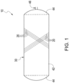
- the present disclosure provides a pressure vessel 10 (sometimes known as a composite overwrapped pressure vessel or "COPV") comprising fibers 20 (such as carbon fiber 20 filaments) wrapped around a tank liner 30.
- the fibers 20 can also be used with embedded layers of fabric or other textiles to enhance performance as needed as would be recognized by one of skill in the art.
- any fiber 20 known in the art can be used with the pressure vessel 10 disclosed herein.
- typical carbon fiber 20 for pressure vessels 10 have a tensile strength about 700 kilo pounds per square inch (ksi) and a tensile modulus of about 33 million pounds per square inch (msi) or higher, so any material with similar characteristics may be used.
- Other fibers 20 overwraps include, but are not limited to, glass fiber, basalt fiber, jute twine, Zylon ® , high-density polyethylene, polypropylene, polyethylene, nylon, Vectran ® and high strength metal wire.
- a carbon fiber 20 overwrap may also include an epoxy or a resin that acts to strengthen and harden the carbon fibers 20.
- the present disclosure is not limited to a pressure vessel 10 comprising a single type of fiber 20, accordingly, it is to be understood that the pressure vessel 10 may be wrapped (or overwrapped) with a plurality of different types of carbon fibers or other fibers 20, depending upon intended use and size of the pressure vessel 10.
- a tank liner 30 having been overwrapped and showing some of the carbon fibers 20 overwrapped onto the tank liner 30 is shown in Fig. 1 .
- the fibers 20 may be wrapped at a continuous "depth" around the tank liner 30, or certain segments of the tank liner 30 may be wrapped with thicker layers of fiber 20. For example, an area known to be subject to greater pressure may have more fibers 20 overwrapped than a section under less pressure.
- fibers 20 may be used on different areas of the pressure vessel subject to different pressures.
- layering patterns may be used in connection with the present disclosure, including without limitation, fibers 20 wound in helical layers, polar layers or hoop layers. Additionally, individual fibers 20 may be wound the same or differing angles relative to the tank liner depending upon the desired traits of the pressure vessel 10.
- epoxies or resins that can be used in connection with the present disclosure.
- Some such resins are EPON ® 828 and 862 and Dow 383, and there are a variety of different curing agents and additives that can be used to adjust the epoxy performance as needed.
- the epoxy or resin can be impregnated onto the fibers 20 before winding or the fibers 20 can be "wet wound” where the epoxy or resin is added as the fibers 20 is wound about the tank liner 30.
- Epoxy is the common resin matrix, but others can be used such as urethanes, polyureas, epoxy vinyl ester, bismaleimide and benzoxazine.
- the present disclosure also provides a pressure vessel 10 with a novel tank liner 30.
- the tank liner 30 may have a variety of shapes (thus imparting a similar shape on the pressure vessel 10 ) including spherical, cylindrical or conical. Of course, combinations of the aforementioned shapes are also within the scope of this disclosure.
- the tank liner 30 acts as a mandrel/tooling that holds the metal end fittings (discussed below) in place and it provides the surface for the application of the permeation barrier.
- the composite mandrel tooling can rely on the permeation layer 50 (discussed below) to contain the gasses and the mandrel can be viewed as fly-away tooling.
- the tank liner 30 comprises a plurality of segments 40 that are bonded together.
- the tank liner 30 is an integral structure comprising only one segment 40.
- the segments 40 can be molded or shaped into a number of configurations.
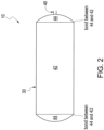
- the tank liner 30 may comprise a plurality of segments 40 wherein one segment 42 forms the cylindrical body of the tank liner and two other segments 44 form the ends or dome caps of the tank liner.
- the cylindrical body of the tank liner 30 may be comprised of several segments 42a, 42b that are bonded together.
- one or both end segments 44 may comprise an end fitting 46 (typically but not exclusively, a hole drilled in the apex of the tooling for the cap segments that is then fitted with a metal fitting that interfaces with the valve connection of a gas system) that is adapted to be connected to a valve or other mechanism useful for allowing the CNG to be vented from the pressure vessel 10.
- the metal end fitting can also be cast or wound in place with mandrel materials. Any end fitting known to those of skill in the art should be considered with the scope of this disclosure. Additionally, the type of end fitting may be varied depending upon the use of the pressure vessel 10.
- the segments 40 comprising the tank liner 30 may comprise many different materials.
- the tank liner 30 may be comprised of a single material while in other embodiments the tank liner 30 may be comprised of a plurality of materials (for example, the end segments 44 may be comprised of a different material than the segments 42 forming the body of the tank liner 30 ) .
- the composition of the tank liner 30 may be varied depending upon the intended use of the pressure vessel 10.
- the segments 42 and 44 may comprise glass fiber reinforced plastics.
- the segments 42 and 44 may comprise carbon fiber reinforced plastics.
- the segments 42 may comprise a glass fiber reinforced material while the end segments 44 are metallic.
- the composite tooling mandrel can be made with a carbon fiber and an epoxy matrix resin, or other resins.
- the composite end segments 44 and metal end fittings 46 can also be outfitted with an-o-ring or sealant material in the metal and non-metallic interfaces.
- An all-metallic end fitting 46 and end segment 44 is especially useful in extremely high pressure situations as the end fittings 46 are not bonded to the end segment 44 but are rather an integral part of the end segment 44.
- the segments must be bonded to one another.
- the segments 40 can have an overlapping joint allowing for a thin bond layer of adhesive to bond the segments 40 together.
- the tank liner 30 may be overwrapped directly by the carbon fiber 20 or it may first be covered by a permeation barrier 50.
- the permeation barrier 50 can be on the inside, outside or both side of the composite mandrel tooling depending on the application.
- the permeation barrier 50 may comprise a polymer such as polyurea or polyurethane or other flexible materials
- the permeation barrier 50 can also contain various fillers and additives to enhance the gas permeation properties.
- the permeation barrier 50 may also comprise an additive such as nanoparticle that helps enhance its performance, such nanoparticles could include, but not be limited to, exfoliated clays or carbon nanotubes. This permeation barrier 50 typically does not add strength to the structure it helps to keep the contents of the pressure vessel 10 from leaking out.
- the permeation barrier 50 can have several layers of different materials that are used to reduce the diffusion of the gasses.
- the carbon fiber 10 may be overwrapped using a traditional filament winding machine.
- the permeation barrier 50 may be interior to the tank liner 30, then the tank liner 30 may be overwrapped with carbon fiber 10.
- the pressure vessel 10 of the present disclosure may be used in a number of applications such as CNG powered automobiles, shipping CNG (by land or sea) or in rockets. Additionally, one or more of the pressure vessels 10 disclosed herein may be included within, or surrounded by, a protective enclosure 60 if the pressure vessels 10 are being used to ship CNG. For example, four pressure vessels 10 may be surrounded by a protective enclosure 60 as shown in Fig. 4 .
- the disclosure of the present invention also comprises the following aspects A1 to A19:
Landscapes
- Engineering & Computer Science (AREA)
- Mechanical Engineering (AREA)
- General Engineering & Computer Science (AREA)
- Filling Or Discharging Of Gas Storage Vessels (AREA)
- Supply Devices, Intensifiers, Converters, And Telemotors (AREA)
- Pressure Vessels And Lids Thereof (AREA)
Abstract
Description
- This application claims the benefit of, and priority to, pending
United States Nonprovisional Application No. 14/525,645 filed on Oct. 28, 2014 U.S. Provisional Application No. 61/945,220 filed Feb. 27, 2014 - The present disclosure pertains to vessels for the transport of pressurized gases and liquids. More specifically, in one embodiment, the present disclosure pertains to vessels for the transport and storage of compressed natural gas ("CNG"), propane, methane, alcohol, helium, hydrogen or argon.
- The desire to supply more environmentally friendly (so called "green") fuels for automobiles and other uses has greatly increased the demand for pressure vessels that can both store and be used in the transport of the fuels. Once of the most promising fuels today is CNG, and the need for cost effective ways of producing pressure vessels for CNG vessels has arisen.
- Generally, the two most expensive features of a CNG pressure vessel are the carbon fibers and the tank liners (around which the carbon fibers are wrapped). The cost of the carbon fibers is largely driven by the free market and thus pressure vessel manufacturers can do little to control or reduce the cost of the carbon fibers. Accordingly, reducing the cost of the tank liners is desirable.
- The most common types of pressure vessels used are: type 3 (metal lined) and type 4 (plastic lined) vessels. There is also a new type 5 vessel being considered by industry. The type 5 vessel is considered to be all-composite (no metallic or non-metallic liner). It may also be considered to be a type 5 vessel if it has a very thin permeation barrier on the inside if it is also non-loadbearing. This disclosure can be applied to a type 4 and/or a type 5 vessel. The common type 3 vessel tank liner is aluminum, but there are also some tank liners produced by welded steel assemblies. The aluminum tank liner size limit is controlled by the diameter of available tube forgings. The diameter size usually stops around 18". There are new emerging markets for trucks and bulk storage systems that need 25" diameter tank liners or larger. This need for the larger diameters has been one of the reasons that more type 4 vessels are being developed. The manufacturing methods for the larger type 4 liners can be costly if there are frequent design changes because the molds and tooling are expensive. The new type 4 vessels however are lighter and cheaper than the aluminum liners for type 3 vessels.
- The production of tank liners however, is not straight forward as it requires specialized tooling and other equipment, and the costs of the required equipment present a significant entry barrier in the industry.
- The present disclosure provides a pressure vessel useful in the transport and storage of gases and liquids, such as CNG that comprises a tank liner with segments that can be bonded together. The pressure vessel of the present disclosure allows for modular manufacturing that is cost effective and readily adaptable to change, more robust end fittings and domes.
- To further provide the advantages and features of the present disclosure, a more particular description of the invention will be rendered by reference to specific embodiments thereof which are illustrated in the appended drawings. It is appreciated that these drawings are not to be considered limiting in scope. The invention will be described and explained with additional specificity and detail through the use of the accompanying drawings in which:
-
Fig. 1 shows one embodiment ofcarbon fiber 20 having been overwrapped onto atank liner 30. -
Fig. 2 shows one embodiment of atank liner 30 disclosed herein. -
Fig. 3 shows an alternate embodiment of atank liner 30 disclosed herein. -
Fig. 4 shows one embodiment of a plurality ofpressure vessels 10 being transported inside of aprotective enclosure 60. - The present disclosure provides a pressure vessel 10 (sometimes known as a composite overwrapped pressure vessel or "COPV") comprising fibers 20 (such as
carbon fiber 20 filaments) wrapped around atank liner 30. Thefibers 20 can also be used with embedded layers of fabric or other textiles to enhance performance as needed as would be recognized by one of skill in the art. - Any
fiber 20 known in the art can be used with thepressure vessel 10 disclosed herein. For example,typical carbon fiber 20 forpressure vessels 10 have a tensile strength about 700 kilo pounds per square inch (ksi) and a tensile modulus of about 33 million pounds per square inch (msi) or higher, so any material with similar characteristics may be used.Other fibers 20 overwraps include, but are not limited to, glass fiber, basalt fiber, jute twine, Zylon®, high-density polyethylene, polypropylene, polyethylene, nylon, Vectran® and high strength metal wire. In some embodiments, acarbon fiber 20 overwrap may also include an epoxy or a resin that acts to strengthen and harden thecarbon fibers 20. The present disclosure is not limited to apressure vessel 10 comprising a single type offiber 20, accordingly, it is to be understood that thepressure vessel 10 may be wrapped (or overwrapped) with a plurality of different types of carbon fibers orother fibers 20, depending upon intended use and size of thepressure vessel 10. One example of atank liner 30 having been overwrapped and showing some of thecarbon fibers 20 overwrapped onto thetank liner 30 is shown inFig. 1 . Thefibers 20 may be wrapped at a continuous "depth" around thetank liner 30, or certain segments of thetank liner 30 may be wrapped with thicker layers offiber 20. For example, an area known to be subject to greater pressure may havemore fibers 20 overwrapped than a section under less pressure. Alternatively, different types offibers 20 may be used on different areas of the pressure vessel subject to different pressures. Additionally, layering patterns may be used in connection with the present disclosure, including without limitation,fibers 20 wound in helical layers, polar layers or hoop layers. Additionally,individual fibers 20 may be wound the same or differing angles relative to the tank liner depending upon the desired traits of thepressure vessel 10. - There are many suitable epoxies or resins that can be used in connection with the present disclosure. Some such resins are EPON® 828 and 862 and Dow 383, and there are a variety of different curing agents and additives that can be used to adjust the epoxy performance as needed. Additionally, the epoxy or resin can be impregnated onto the
fibers 20 before winding or thefibers 20 can be "wet wound" where the epoxy or resin is added as thefibers 20 is wound about thetank liner 30. Epoxy is the common resin matrix, but others can be used such as urethanes, polyureas, epoxy vinyl ester, bismaleimide and benzoxazine. - The present disclosure also provides a
pressure vessel 10 with anovel tank liner 30. Thetank liner 30 may have a variety of shapes (thus imparting a similar shape on the pressure vessel 10) including spherical, cylindrical or conical. Of course, combinations of the aforementioned shapes are also within the scope of this disclosure. In one embodiment, thetank liner 30 acts as a mandrel/tooling that holds the metal end fittings (discussed below) in place and it provides the surface for the application of the permeation barrier. The composite mandrel tooling can rely on the permeation layer 50 (discussed below) to contain the gasses and the mandrel can be viewed as fly-away tooling. - In one embodiment, the
tank liner 30 comprises a plurality of segments 40 that are bonded together. In an alternate embodiment, thetank liner 30 is an integral structure comprising only one segment 40. The segments 40 can be molded or shaped into a number of configurations. For example, as shown inFig. 2 , thetank liner 30 may comprise a plurality of segments 40 wherein onesegment 42 forms the cylindrical body of the tank liner and twoother segments 44 form the ends or dome caps of the tank liner. Alternatively, as shown inFig. 3 , the cylindrical body of thetank liner 30 may be comprised ofseveral segments - Depending upon the intended use of the
pressure vessel 10, one or bothend segments 44 may comprise an end fitting 46 (typically but not exclusively, a hole drilled in the apex of the tooling for the cap segments that is then fitted with a metal fitting that interfaces with the valve connection of a gas system) that is adapted to be connected to a valve or other mechanism useful for allowing the CNG to be vented from thepressure vessel 10. The metal end fitting can also be cast or wound in place with mandrel materials. Any end fitting known to those of skill in the art should be considered with the scope of this disclosure. Additionally, the type of end fitting may be varied depending upon the use of thepressure vessel 10. - The segments 40 comprising the
tank liner 30 may comprise many different materials. In one embodiment, thetank liner 30 may be comprised of a single material while in other embodiments thetank liner 30 may be comprised of a plurality of materials (for example, theend segments 44 may be comprised of a different material than thesegments 42 forming the body of the tank liner 30). The composition of thetank liner 30 may be varied depending upon the intended use of thepressure vessel 10. In one application, thesegments segments segments 42 may comprise a glass fiber reinforced material while theend segments 44 are metallic. If weight is critical, the composite tooling mandrel can be made with a carbon fiber and an epoxy matrix resin, or other resins. Thecomposite end segments 44 andmetal end fittings 46 can also be outfitted with an-o-ring or sealant material in the metal and non-metallic interfaces. An all-metallic end fitting 46 andend segment 44 is especially useful in extremely high pressure situations as theend fittings 46 are not bonded to theend segment 44 but are rather an integral part of theend segment 44. - In the embodiments where the
tank liner 30 comprises more than one segment 40, the segments must be bonded to one another. The segments 40 can have an overlapping joint allowing for a thin bond layer of adhesive to bond the segments 40 together. - The
tank liner 30 may be overwrapped directly by thecarbon fiber 20 or it may first be covered by a permeation barrier 50. The permeation barrier 50 can be on the inside, outside or both side of the composite mandrel tooling depending on the application. The permeation barrier 50 may comprise a polymer such as polyurea or polyurethane or other flexible materials The permeation barrier 50 can also contain various fillers and additives to enhance the gas permeation properties. In one embodiment the permeation barrier 50 may also comprise an additive such as nanoparticle that helps enhance its performance, such nanoparticles could include, but not be limited to, exfoliated clays or carbon nanotubes. This permeation barrier 50 typically does not add strength to the structure it helps to keep the contents of thepressure vessel 10 from leaking out. One of the main functions of the permeation barrier 50 is to contain the gasses within thetank liner 30. The permeation barrier 50 can have several layers of different materials that are used to reduce the diffusion of the gasses. Once the permeation barrier 50 is added over thetank liner 30, thecarbon fiber 10 may be overwrapped using a traditional filament winding machine. In one embodiment, the permeation barrier 50 may be interior to thetank liner 30, then thetank liner 30 may be overwrapped withcarbon fiber 10. In yet another alternate embodiment, there may be two (2) permeation barriers 50, one interior to thetank liner 30 and one exterior to thetank liner 30. - The
pressure vessel 10 of the present disclosure may be used in a number of applications such as CNG powered automobiles, shipping CNG (by land or sea) or in rockets. Additionally, one or more of thepressure vessels 10 disclosed herein may be included within, or surrounded by, aprotective enclosure 60 if thepressure vessels 10 are being used to ship CNG. For example, fourpressure vessels 10 may be surrounded by aprotective enclosure 60 as shown inFig. 4 . - Although particular embodiments of the present disclosure have been described, it is not intended that such references be construed as limitations upon the scope of this disclosure except as set forth in the claims.
- The disclosure of the present invention also comprises the following aspects A1 to A19:
- A1. A pressure vessel comprising:
- a. a carbon fiber overwrap;
- b. a polymeric permeation barrier; and
- c. a tank liner, wherein the tank liner comprises fiber reinforced plastic.
- A2. The pressure vessel of A1 wherein the polymeric material is selected from the group consisting of polyurethane and polyurea.
- A3. The pressure vessel of A2 wherein the permeation barrier further comprises a nanoparticle additive.
- A4. The pressure vessel of A3 wherein the nanoparticle additive is selected from the group consisting of exfoliated clay and carbon nanotubes.
- A5. The pressure vessel of A1 wherein the permeation barrier further comprises a nanoparticle additive selected from the group consisting of exfoliated clay and carbon nanotubes.
- A6. The pressure vessel of A5 wherein the tank liner is an integral structure.
- A7. The pressure vessel of A6 wherein the tank liner further comprises carbon fibers.
- A8. The pressure vessel of A7 wherein the tank liner comprises a plurality of central segments and cap segments.
- A9. The pressure vessel of A8 wherein the cap segments are comprised of a metal.
- A10. A pressure vessel comprising a tank liner wherein said tank liner further comprises fiber reinforced plastic.
- A11. The pressure vessel of A10 wherein the tank liner is an integral structure.
- A12. The pressure vessel of A10 wherein the tank liner further comprises carbon fibers.
- A13. The pressure vessel of A12 wherein the tank liner comprises a plurality of central segments and cap segments.
- A14. The pressure vessel of A13 wherein the cap segments are comprised of a metal.
- A15. The pressure vessel of A10 wherein the tank liner is overlaid by a wound carbon fiber layer.
- A16. The pressure vessel of A15 wherein the wound carbon fiber layer comprises a carbon fiber having a tensile strength of about 700 KSI and a modulus approximately 33 MSI.
- A17. The pressure vessel of A16, wherein the wound carbon fiber layer is of a uniform continuous thickness around the tank liner.
- A18. The pressure vessel of A17 further comprising a permeation barrier located between the tank liner and the wound carbon fiber layer.
- A19. The pressure vessel of A18 further comprising a second permeation barrier interior to a composite tooling/mandrel.
Claims (14)
- Use of a tank liner (30) comprising fiber reinforced plastic, as mandrel tooling in the manufacture of a pressure vessel (10), for providing the surface for the application of a permeation barrier (50) to the tank liner (30) and preferably for holding metal end fittings (44) in place.
- Use according to claim 1, wherein the body of the tank liner (30) is cylindrical and is comprised of several segments (42a, 42b) that are bonded together.
- Use according to claim 2, wherein the segments (42a, 42b) comprise glass fiber reinforced material, preferably glass fiber reinforced plastic.
- Use according to any one of claims 2 to 3, wherein the segments (42a, 42b) are bonded to one another and have an overlapping joint allowing for a thin bond layer of adhesive to bond the segments (42a, 42b) together.
- Use according to any one of claims 1 to 4, wherein the application of the permeation barrier (50) is on the inside, on the outside or on both sides of the mandrel tooling.
- Use according to anyone of claims 1 to 5, wherein the permeation barrier (50) comprises a polymer selected from the group consisting of polyurea and polyurethane, and preferably further comprises fillers and/or additives.
- Use according to any one of claims 1 to 6 wherein the permeation barrier (50) comprises nanoparticles as additives, preferably selected from the group consisting of exfoliated clay and nanotubes.
- Use according to anyone of claims 1 to 7, wherein the tank liner (30) is as defined in any one of claims 9 to 12 and/or the pressure vessel (10) is as defined in any one of claims 9 to 14.
- A pressure vessel (10) comprising a tank liner (30) wherein said tank liner (30) further comprises fiber reinforced plastic.
- The pressure vessel (10) of claim 9, wherein the tank liner (30) further comprises carbon fibers.
- The pressure vessel (10) of claim10, wherein the tank liner (30) comprises a plurality of central segments (42a, 42b) and cap segments (44), wherein preferably the cap segments (44) are comprised of a metal.
- The pressure vessel (10) of claim 9 wherein the tank liner (30) is overlaid by a wound carbon fiber layer,
wherein preferably the wound carbon fiber layer comprises a carbon fiber having a tensile strength of 700 KSI (4.83 × 10³ MPa) and a modulus of 33 MSI (227.5 × 10³) and wherein preferably the wound carbon fiber layer is of a uniform continuous thickness around the tank liner (30). - The pressure vessel (10) of claim 12, further comprising a permeation barrier (50) located between the tank liner (30) and the wound carbon fiber layer,
wherein preferably the permeation barrier (50) further comprises a nanoparticle additive and wherein preferably the nanoparticle additive is selected from the group consisting of exfoliated clay and carbon nanotubes. - The pressure vessel (10) of claim 13, further comprising a second permeation barrier interior to a composite tooling/mandrel.
Applications Claiming Priority (4)
| Application Number | Priority Date | Filing Date | Title |
|---|---|---|---|
| US201461945220P | 2014-02-27 | 2014-02-27 | |
| US14/525,645 US11353160B2 (en) | 2014-02-27 | 2014-10-28 | Pressure vessel |
| PCT/US2015/017061 WO2015130599A1 (en) | 2014-02-27 | 2015-02-23 | Pressure vessel |
| EP15754903.1A EP3111130B1 (en) | 2014-02-27 | 2015-02-23 | Pressure vessel |
Related Parent Applications (1)
| Application Number | Title | Priority Date | Filing Date |
|---|---|---|---|
| EP15754903.1A Division EP3111130B1 (en) | 2014-02-27 | 2015-02-23 | Pressure vessel |
Publications (1)
| Publication Number | Publication Date |
|---|---|
| EP4220002A1 true EP4220002A1 (en) | 2023-08-02 |
Family
ID=53881814
Family Applications (2)
| Application Number | Title | Priority Date | Filing Date |
|---|---|---|---|
| EP15754903.1A Active EP3111130B1 (en) | 2014-02-27 | 2015-02-23 | Pressure vessel |
| EP23156246.3A Pending EP4220002A1 (en) | 2014-02-27 | 2015-02-23 | Pressure vessel |
Family Applications Before (1)
| Application Number | Title | Priority Date | Filing Date |
|---|---|---|---|
| EP15754903.1A Active EP3111130B1 (en) | 2014-02-27 | 2015-02-23 | Pressure vessel |
Country Status (9)
| Country | Link |
|---|---|
| US (2) | US11353160B2 (en) |
| EP (2) | EP3111130B1 (en) |
| JP (1) | JP2017512286A (en) |
| DK (1) | DK3111130T3 (en) |
| ES (1) | ES2942709T3 (en) |
| FI (1) | FI3111130T3 (en) |
| PL (1) | PL3111130T3 (en) |
| PT (1) | PT3111130T (en) |
| WO (1) | WO2015130599A1 (en) |
Families Citing this family (12)
| Publication number | Priority date | Publication date | Assignee | Title |
|---|---|---|---|---|
| US11015761B1 (en) * | 2013-11-22 | 2021-05-25 | CleanNG, LLC | Composite pressure vessel for gas storage and method for its production |
| US11353160B2 (en) * | 2014-02-27 | 2022-06-07 | Hanwha Cimarron Llc | Pressure vessel |
| CN105371100B (en) * | 2014-08-29 | 2021-01-05 | 中材科技(苏州)有限公司 | Composite material container and forming method of composite material layer thereof |
| US11065827B2 (en) | 2015-11-02 | 2021-07-20 | Teijin Carbon America, Inc. | Thermoplastic composite in-situ melt processing method for composite overwrapped tools |
| US10724684B2 (en) * | 2016-09-20 | 2020-07-28 | Amtrol Licensing Inc. | Fiberwound tanks |
| JP6601425B2 (en) | 2017-01-18 | 2019-11-06 | トヨタ自動車株式会社 | Gas tank liners and gas tanks |
| JP6766756B2 (en) * | 2017-06-08 | 2020-10-14 | 豊田合成株式会社 | Pressure-resistant container |
| MX2020003797A (en) * | 2017-09-28 | 2020-11-09 | Carboclave Corp | Displaced air carbonation (dac) process and system. |
| US11440399B2 (en) | 2019-03-22 | 2022-09-13 | Agility Fuel Systems Llc | Fuel system mountable to a vehicle frame |
| US20200347992A1 (en) | 2019-05-02 | 2020-11-05 | Agility Fuel Systems Llc | Polymeric liner based gas cylinder with reduced permeability |
| CN111207288A (en) * | 2020-01-13 | 2020-05-29 | 山东特爱纳米科技有限公司 | Multifunctional hydrogen storage container and application |
| GB202016223D0 (en) * | 2020-10-13 | 2020-11-25 | Rolls Royce Plc | Organic composite gas storage tank |
Citations (6)
| Publication number | Priority date | Publication date | Assignee | Title |
|---|---|---|---|---|
| WO1991018239A1 (en) * | 1990-05-22 | 1991-11-28 | Kb Komposit Försäljnings Ab | A container, particularly for pressure fluid |
| US20020155232A1 (en) * | 2001-04-24 | 2002-10-24 | Delay Thomas K. | Multilayer composite pressure vessel |
| US20040149759A1 (en) * | 2001-04-25 | 2004-08-05 | Moser Eva Maria | Gastight container |
| US20050173430A1 (en) * | 2002-05-03 | 2005-08-11 | Ludo Van Schepdael | Plastic pressure vessel for a fluid and method of manufacturing such a vessel |
| US7803241B2 (en) * | 2002-04-12 | 2010-09-28 | Microcosm, Inc. | Composite pressure tank and process for its manufacture |
| US20120175098A1 (en) * | 2011-01-06 | 2012-07-12 | Bpg, Llc | Systems and methods to insulate components of industrial infrastructure |
Family Cites Families (103)
| Publication number | Priority date | Publication date | Assignee | Title |
|---|---|---|---|---|
| US2744043A (en) * | 1950-01-23 | 1956-05-01 | Fels & Company | Method of producing pressure containers for fluids |
| US3047191A (en) * | 1957-11-26 | 1962-07-31 | Hercules Powder Co Ltd | Filament wound vessels and methods for forming same |
| US3073475A (en) | 1959-10-30 | 1963-01-15 | Minnesota Mining & Mfg | Pressure vessel and method of making the same |
| US3207352A (en) * | 1962-12-04 | 1965-09-21 | Jr Theodore J Reinhart | Laminated pressure vessels |
| GB995684A (en) * | 1963-05-24 | 1965-06-23 | Metal Containers Ltd | Container for pressure fluid |
| US3360411A (en) * | 1964-10-15 | 1967-12-26 | Koppers Co Inc | Method of forming a hollow container of wound filamentary material |
| US3508677A (en) | 1968-08-20 | 1970-04-28 | Whittaker Corp | Vessel for storing high-pressure gases |
| US3937781A (en) * | 1971-05-20 | 1976-02-10 | Structural Fibers, Inc. | Method for forming fiber-reinforced plastic articles |
| US3866792A (en) * | 1973-03-02 | 1975-02-18 | Hercules Inc | Integral filament reinforced composite-rocket chamber/adapter |
| CH558746A (en) * | 1973-05-28 | 1975-02-14 | Basler Stueckfaerberei Ag | CYLINDRICAL RESERVOIR MADE OF FIBER REINFORCED PLASTIC AND THE METHOD FOR MANUFACTURING THE SAME. |
| US4504530A (en) * | 1982-03-17 | 1985-03-12 | Structural Fibers, Inc. | Lined pressure vessels |
| DE3426158C1 (en) * | 1984-07-16 | 1985-12-19 | M.A.N. Maschinenfabrik Augsburg-Nürnberg AG, 8000 München | Pressure vessel made of fiber-reinforced plastic and process for its production |
| US4699288A (en) * | 1986-04-28 | 1987-10-13 | Edo Corporation/Fiber Science Division | High pressure vessel construction |
| US4773952A (en) * | 1987-08-03 | 1988-09-27 | Biomagnetic Technologies, Inc. | Nonmetallic cylindrical cryogenic container |
| SE463834B (en) * | 1988-03-15 | 1991-01-28 | Asea Plast Ab | TRYCKKAERL |
| GB8818622D0 (en) * | 1988-08-05 | 1988-09-07 | British Petroleum Co Plc | Container for high pressure gases |
| US4982856A (en) * | 1989-06-23 | 1991-01-08 | General Electric Company | High temperature, high pressure continuous random glass fiber reinforced thermoplastic fluid vessel and method of making |
| US5150812A (en) | 1990-07-05 | 1992-09-29 | Hoechst Celanese Corporation | Pressurized and/or cryogenic gas containers and conduits made with a gas impermeable polymer |
| SE468649B (en) * | 1991-05-24 | 1993-02-22 | Kb Komposit Foersaeljnings Ab | ARMED PLASTIC CONTAINER, SATISFIED TO ASTAD A COMBUSTION BODY FOR THIS AND APPLIANCE BEFORE IMPLEMENTING THE SET |
| US5358683A (en) * | 1993-04-08 | 1994-10-25 | Davidson Textron Inc. | Process of making a continuous fiber reinforced thermoplastic article |
| US5419139A (en) * | 1993-12-13 | 1995-05-30 | Martin Marietta Corporation | Composite cryogenic tank apparatus |
| JPH08219387A (en) | 1995-02-15 | 1996-08-30 | Toray Ind Inc | Gas cylinder |
| US5655299A (en) * | 1995-06-07 | 1997-08-12 | State Industries, Inc. | Method of fabricating a tank and method of fabricating a tank connector therefor |
| CA2212244C (en) * | 1995-12-04 | 2007-05-29 | Toray Industries, Inc. | Pressure vessel and process for producing the same |
| JPH09280496A (en) | 1996-04-18 | 1997-10-31 | Toray Ind Inc | Pressure vessel and its manufacture |
| US5697511A (en) * | 1996-09-27 | 1997-12-16 | Boeing North American, Inc. | Tank and method of fabrication |
| SE511172C2 (en) * | 1996-11-04 | 1999-08-16 | Composite Scandinavia Ab | Reinforced plastic container, process for its manufacture and apparatus for carrying out the process |
| MY125147A (en) * | 1998-10-27 | 2006-07-31 | Univ Johns Hopkins | Compressed gas manifold |
| US6158605A (en) * | 1998-12-22 | 2000-12-12 | The United States Of America As Represented By The Administrator Of The National Aeronautics And Space Administration | Composite tank |
| JP2000249294A (en) | 1999-03-03 | 2000-09-12 | Toray Ind Inc | Pressure vessel and manufacture thereof |
| US6460721B2 (en) * | 1999-03-23 | 2002-10-08 | Exxonmobil Upstream Research Company | Systems and methods for producing and storing pressurized liquefied natural gas |
| US6613408B1 (en) * | 1999-12-18 | 2003-09-02 | Delphi Technologies, Inc. | Fuel permeation barrier fuel tank |
| US6364197B1 (en) * | 2000-08-04 | 2002-04-02 | The Boeing Company | Friction stir welding of containers from the interior |
| US20050001100A1 (en) * | 2000-09-19 | 2005-01-06 | Kuang Hsi-Wu | Reinforced foam covering for cryogenic fuel tanks |
| US6716503B1 (en) * | 2000-11-30 | 2004-04-06 | Adc Acquisition Company | Reinforced thermoplastic storage vessel manufacture |
| JP2002188794A (en) * | 2000-12-21 | 2002-07-05 | Honda Motor Co Ltd | High pressure hydrogen tank and manufacturing method thereof |
| JP4049580B2 (en) * | 2001-01-31 | 2008-02-20 | 豊田合成株式会社 | High pressure gas container liner and high pressure gas container |
| US6660214B2 (en) * | 2001-02-23 | 2003-12-09 | Essef Corporation | Pressure vessel manufacture method |
| BE1019794A5 (en) * | 2011-07-12 | 2012-12-04 | Covess N V | METHOD FOR MANUFACTURING PRESSURE-RESISTANT GAS AND / OR LIQUID-PROOF RECIPIENTS. |
| US7195133B1 (en) | 2002-04-12 | 2007-03-27 | Microcosm, Inc. | Composite pressure tank and process for its manufacture |
| US6953129B2 (en) * | 2002-08-27 | 2005-10-11 | The United States Of America As Represented By The Administrator Of The National Aeronautics And Space Administration | Pressure vessel with impact and fire resistant coating and method of making same |
| US20040168773A1 (en) * | 2002-10-10 | 2004-09-02 | Hauber David E. | Reinforced thin wall thermoplastic storage vessel manufacture |
| JP2004286201A (en) | 2003-01-29 | 2004-10-14 | Toyoda Gosei Co Ltd | High pressure gas container and its manufacturing method |
| AT7582U1 (en) | 2003-02-18 | 2005-05-25 | Magna Steyr Fahrzeugtechnik Ag | DOUBLE-WALLED CONTAINER FOR CRYOGENEOUS LIQUIDS |
| WO2005087854A2 (en) | 2003-10-10 | 2005-09-22 | Dow Global Technologies Inc. | Composite of exfoliated clay in soot and the preparation thereof |
| JP4436148B2 (en) * | 2004-02-09 | 2010-03-24 | 本田技研工業株式会社 | Pressure vessel liner and method of manufacturing the same |
| WO2005096712A2 (en) * | 2004-04-08 | 2005-10-20 | Showa Denko K.K. | Process for fabricating pressure vessel liner |
| US7641949B2 (en) * | 2004-05-20 | 2010-01-05 | The United States Of America As Represented By The Administrator Of The National Aeronautics And Space Administration | Pressure vessel with improved impact resistance and method of making the same |
| US8297468B1 (en) * | 2004-05-20 | 2012-10-30 | The United States Of America As Represented By The Administrator Of The National Aeronautics And Space Administration | Fuel tank for liquefied natural gas |
| FR2871091B1 (en) * | 2004-06-03 | 2008-01-18 | Commissariat Energie Atomique | METHOD FOR MANUFACTURING A SEAL SPEED OF TYPE IV TANK AND TYPE IV TANK |
| WO2006004136A1 (en) * | 2004-07-06 | 2006-01-12 | Honda Motor Co., Ltd. | Pressure vessel |
| JP4599118B2 (en) * | 2004-08-30 | 2010-12-15 | 富士重工業株式会社 | Fuel tank |
| US7287663B2 (en) * | 2005-01-05 | 2007-10-30 | Amtrol Inc. | Lined pressure vessel and connector therefor |
| JP2006342895A (en) | 2005-06-09 | 2006-12-21 | Toyota Motor Corp | High pressure tank |
| US20070077480A1 (en) | 2005-10-05 | 2007-04-05 | Curello Andrew J | Scavenger materials in fuel cartridge |
| FR2893622B1 (en) * | 2005-11-24 | 2007-12-21 | Commissariat Energie Atomique | CAPROLACTAM-BASED COMPOSITION, METHOD OF MANUFACTURING SEALING ELEMENT, AND TANK |
| EP1850058A1 (en) * | 2006-04-25 | 2007-10-31 | Inergy Automotive Systems Research (SA) | Storage tank |
| JP5123495B2 (en) * | 2006-06-14 | 2013-01-23 | 帝人ファイバー株式会社 | Membrane material for gas holder and gas holder using the same |
| FR2902364B1 (en) * | 2006-06-16 | 2012-04-27 | Commissariat Energie Atomique | METHOD FOR MANUFACTURING A THERMOSETTING POLYMER SEALANT FOR A RESERVOIR CONTAINING A PRESSURIZED FLUID, SUCH AS A COMPOSITE TANK, AND TANK |
| US8308017B2 (en) * | 2007-02-22 | 2012-11-13 | GM Global Technology Operations LLC | Composite material with fibers with different stiffness for optimum stress usage |
| US8858857B2 (en) * | 2007-03-12 | 2014-10-14 | Geoffrey Michael Wood | Process for the rapid fabrication of composite gas cylinders and related shapes |
| US7867589B2 (en) * | 2007-07-20 | 2011-01-11 | The United States Of America As Represented By The Administrator Of The National Aeronautics And Space Administration | Hybrid cryogenic tank construction and method of manufacture therefor |
| US8815360B2 (en) * | 2007-08-28 | 2014-08-26 | Cryovac, Inc. | Multilayer film having passive and active oxygen barrier layers |
| US7870971B2 (en) * | 2007-08-29 | 2011-01-18 | GM Global Technology Operations LLC | Diffusion layer for pressure vessels |
| JP2009255399A (en) | 2008-04-17 | 2009-11-05 | Oji Paper Co Ltd | Gas barrier laminated body and method for manufacturing the same |
| WO2009155728A1 (en) * | 2008-06-23 | 2009-12-30 | Lanxess Deutschland Gmbh | Carbon nanotube containing rubber compositions |
| WO2009156442A2 (en) * | 2008-06-25 | 2009-12-30 | Inergy Automotive Systems Research (Société Anonyme) | Method for manufacturing a storage tank |
| JP4552159B2 (en) | 2008-07-09 | 2010-09-29 | トヨタ自動車株式会社 | Gas tank and gas tank manufacturing method |
| US8449705B1 (en) * | 2008-09-09 | 2013-05-28 | Scorpius Space Launch Company Incorporated | Techniques for making pressure vessels as unitary structures of composite materials |
| CA2746455C (en) | 2008-12-15 | 2017-01-03 | 3M Innovative Properties Company | Surfacing film for composites with barrier layer |
| CA2751453C (en) * | 2009-02-06 | 2017-09-19 | Hexagon Technology As | Pressure vessel longitudinal vents |
| US8602250B2 (en) * | 2009-05-04 | 2013-12-10 | GM Global Technology Operations LLC | Storage vessel and method of forming |
| JP2011017379A (en) | 2009-07-08 | 2011-01-27 | Toyota Motor Corp | Gas tank |
| DE102009049948B4 (en) | 2009-10-19 | 2012-02-02 | Kautex Maschinenbau Gmbh | pressure vessel |
| US8561829B1 (en) * | 2009-10-23 | 2013-10-22 | The United States Of America As Represented By The Administrator Of The National Aeronautics And Space Administration | Composite pressure vessel including crack arresting barrier |
| US9074685B2 (en) | 2010-02-26 | 2015-07-07 | GM Global Technology Operations LLC | Extruded tube welded vessel liner with injection molded end caps |
| DE102010017413B4 (en) * | 2010-06-17 | 2012-08-30 | Xperion Gmbh | Pressure vessel for storing a fluid |
| US9205373B2 (en) * | 2010-11-29 | 2015-12-08 | Quantum Fuel Systems Trechnologies Worldwide, Inc. | Breather layer for exhausting permeate from pressure vessels |
| JP5621631B2 (en) * | 2011-02-02 | 2014-11-12 | トヨタ自動車株式会社 | High pressure tank manufacturing method and high pressure tank |
| US20140008373A1 (en) * | 2011-04-01 | 2014-01-09 | Luxfer Canada Limited | Multilayer liner for a high-pressure gas cylinder |
| US20130313266A1 (en) * | 2011-06-15 | 2013-11-28 | Basell Polyolefine Gmbh | Method to improve the barrier properties of composite gas cylinders and high pressure gas cylinder having enhanced barrier properties |
| US9243751B2 (en) | 2012-01-20 | 2016-01-26 | Lightsail Energy, Inc. | Compressed gas storage unit |
| JP6000618B2 (en) | 2012-04-24 | 2016-09-28 | 中国工業株式会社 | High pressure gas container and method for manufacturing high pressure gas container |
| WO2013191746A1 (en) * | 2012-06-20 | 2013-12-27 | Hypercomp Engineering, Inc. | Port/liner assembly for pressure vessel |
| DE202012013354U1 (en) * | 2012-07-16 | 2016-07-01 | Elkamet Kunststofftechnik Gmbh | pressure vessel |
| JP5904081B2 (en) * | 2012-10-05 | 2016-04-13 | トヨタ自動車株式会社 | Pressure vessel and production method thereof |
| CA2805826C (en) * | 2013-02-11 | 2019-11-05 | Glen Aylward | Tank made of a composite material and closed molding process for manufacturing the same |
| JP5999039B2 (en) * | 2013-07-10 | 2016-09-28 | トヨタ自動車株式会社 | High-pressure tank and method for manufacturing high-pressure tank |
| US11015761B1 (en) * | 2013-11-22 | 2021-05-25 | CleanNG, LLC | Composite pressure vessel for gas storage and method for its production |
| US11353160B2 (en) * | 2014-02-27 | 2022-06-07 | Hanwha Cimarron Llc | Pressure vessel |
| US20150316207A1 (en) * | 2014-05-02 | 2015-11-05 | Infinite Composites, LLC | Composite Pressure Vessel Integrated Mandrel |
| JP6489519B2 (en) * | 2014-10-23 | 2019-03-27 | ニッタ株式会社 | Method for producing reinforcing fiber |
| DE102014016023B3 (en) * | 2014-10-29 | 2016-03-24 | Daimler Ag | Compressed gas containers |
| CN107709503B (en) * | 2015-06-26 | 2019-06-18 | 日本瑞翁株式会社 | Gas sealant member composition and gas sealant member |
| JP2017115938A (en) * | 2015-12-22 | 2017-06-29 | ニッタ株式会社 | High pressure vessel and process of manufacture of high pressure vessel |
| US10648620B2 (en) * | 2016-03-16 | 2020-05-12 | Hexagon Technology As | Vented fitting for pressure vessel boss |
| US10088110B2 (en) * | 2016-05-17 | 2018-10-02 | Hexagon Technology As | Pressure vessel liner venting via nanotextured surface |
| KR101856323B1 (en) * | 2016-05-18 | 2018-05-10 | 현대자동차주식회사 | Pressure vessel having degassing structure |
| JP6720898B2 (en) * | 2017-03-09 | 2020-07-08 | トヨタ自動車株式会社 | High pressure tank |
| DE102019107983A1 (en) * | 2019-03-28 | 2020-10-01 | Bayerische Motoren Werke Aktiengesellschaft | Process for producing a barrier layer for a pressure vessel and pressure vessel |
| US20200347992A1 (en) * | 2019-05-02 | 2020-11-05 | Agility Fuel Systems Llc | Polymeric liner based gas cylinder with reduced permeability |
| US11559964B2 (en) * | 2019-06-06 | 2023-01-24 | Northrop Grumman Systems Corporation | Composite structures, composite storage tanks, vehicles including such composite storage tanks, and related systems and methods |
| US11299036B2 (en) * | 2019-11-06 | 2022-04-12 | GM Global Technology Operations LLC | Hydrogen storage tank having a nanoporous breather layer |
-
2014
- 2014-10-28 US US14/525,645 patent/US11353160B2/en active Active
-
2015
- 2015-02-23 PT PT157549031T patent/PT3111130T/en unknown
- 2015-02-23 DK DK15754903.1T patent/DK3111130T3/en active
- 2015-02-23 JP JP2016554623A patent/JP2017512286A/en active Pending
- 2015-02-23 FI FIEP15754903.1T patent/FI3111130T3/en active
- 2015-02-23 EP EP15754903.1A patent/EP3111130B1/en active Active
- 2015-02-23 PL PL15754903.1T patent/PL3111130T3/en unknown
- 2015-02-23 EP EP23156246.3A patent/EP4220002A1/en active Pending
- 2015-02-23 WO PCT/US2015/017061 patent/WO2015130599A1/en active Application Filing
- 2015-02-23 ES ES15754903T patent/ES2942709T3/en active Active
-
2022
- 2022-05-16 US US17/745,370 patent/US20220275909A1/en active Pending
Patent Citations (6)
| Publication number | Priority date | Publication date | Assignee | Title |
|---|---|---|---|---|
| WO1991018239A1 (en) * | 1990-05-22 | 1991-11-28 | Kb Komposit Försäljnings Ab | A container, particularly for pressure fluid |
| US20020155232A1 (en) * | 2001-04-24 | 2002-10-24 | Delay Thomas K. | Multilayer composite pressure vessel |
| US20040149759A1 (en) * | 2001-04-25 | 2004-08-05 | Moser Eva Maria | Gastight container |
| US7803241B2 (en) * | 2002-04-12 | 2010-09-28 | Microcosm, Inc. | Composite pressure tank and process for its manufacture |
| US20050173430A1 (en) * | 2002-05-03 | 2005-08-11 | Ludo Van Schepdael | Plastic pressure vessel for a fluid and method of manufacturing such a vessel |
| US20120175098A1 (en) * | 2011-01-06 | 2012-07-12 | Bpg, Llc | Systems and methods to insulate components of industrial infrastructure |
Also Published As
| Publication number | Publication date |
|---|---|
| EP3111130B1 (en) | 2023-02-15 |
| US20150240993A1 (en) | 2015-08-27 |
| ES2942709T3 (en) | 2023-06-06 |
| US20220275909A1 (en) | 2022-09-01 |
| US11353160B2 (en) | 2022-06-07 |
| EP3111130A4 (en) | 2018-02-21 |
| WO2015130599A1 (en) | 2015-09-03 |
| EP3111130A1 (en) | 2017-01-04 |
| PT3111130T (en) | 2023-03-03 |
| DK3111130T3 (en) | 2023-02-27 |
| JP2017512286A (en) | 2017-05-18 |
| PL3111130T3 (en) | 2023-05-29 |
| FI3111130T3 (en) | 2023-04-26 |
Similar Documents
| Publication | Publication Date | Title |
|---|---|---|
| US20220275909A1 (en) | Pressure Vessel | |
| US11898701B2 (en) | Composite pressure vessel assembly and method of manufacturing | |
| US10563818B1 (en) | Basalt-based pressure vessel for gas storage and method for its production | |
| EP2433045B1 (en) | High pressure storage device and method | |
| WO2013083662A4 (en) | Ultra-high operating pressure vessel | |
| US20160348839A1 (en) | High-pressure composite vessel and the method of manufacturing high-pressure composite vessel | |
| US9618157B2 (en) | Concentric shells for compressed gas storage | |
| CA2912415A1 (en) | Hydrogen storage tank | |
| GB2489610A (en) | Multilayer liner for a high-pressure gas cylinder | |
| CN108692180B (en) | Compressed gas closure article with barrier coating | |
| WO2007043689A9 (en) | Gas tank and method for producing same | |
| US20150316207A1 (en) | Composite Pressure Vessel Integrated Mandrel | |
| JP2016142349A (en) | Pressure container | |
| CN111251631A (en) | High pressure hydrogen storage cylinder and method of manufacturing the same | |
| US11105465B2 (en) | Pressure vessel | |
| JP2012052588A (en) | Method for manufacturing pressure vessel, and pressure vessel | |
| CN113574307A (en) | Method for producing a barrier layer of a pressure vessel and pressure vessel | |
| JP4578068B2 (en) | Laminated body for shell and pressure vessel using the same | |
| JP5395156B2 (en) | Gas tank and manufacturing method thereof | |
| JP2010276146A (en) | High-pressure hydrogen tank | |
| JP2005113971A (en) | Liner for pressure resistant container | |
| WO2018079818A1 (en) | Pressure container and container body | |
| Shivamurthy et al. | Design, fabrication, and testing of epoxy/glass-reinforced pressure vessel for high-pressure gas storage | |
| CN114248477A (en) | Method for forming body of plastic lining high-pressure gas cylinder | |
| RU213938U1 (en) | LARGE-SIZED CYLINDER FOR COMPRESSED HYDROGEN GAS WITH A POLYMER-COMPOSITE SHELL |
Legal Events
| Date | Code | Title | Description |
|---|---|---|---|
| PUAI | Public reference made under article 153(3) epc to a published international application that has entered the european phase |
Free format text: ORIGINAL CODE: 0009012 |
|
| STAA | Information on the status of an ep patent application or granted ep patent |
Free format text: STATUS: THE APPLICATION HAS BEEN PUBLISHED |
|
| AC | Divisional application: reference to earlier application |
Ref document number: 3111130 Country of ref document: EP Kind code of ref document: P |
|
| AK | Designated contracting states |
Kind code of ref document: A1 Designated state(s): AL AT BE BG CH CY CZ DE DK EE ES FI FR GB GR HR HU IE IS IT LI LT LU LV MC MK MT NL NO PL PT RO RS SE SI SK SM TR |
|
| STAA | Information on the status of an ep patent application or granted ep patent |
Free format text: STATUS: REQUEST FOR EXAMINATION WAS MADE |
|
| 17P | Request for examination filed |
Effective date: 20240202 |
|
| RBV | Designated contracting states (corrected) |
Designated state(s): AL AT BE BG CH CY CZ DE DK EE ES FI FR GB GR HR HU IE IS IT LI LT LU LV MC MK MT NL NO PL PT RO RS SE SI SK SM TR |