EP4217552B1 - Système auto-grimpant pour un corps structural en béton et procédé auto-grimpant - Google Patents
Système auto-grimpant pour un corps structural en béton et procédé auto-grimpant Download PDFInfo
- Publication number
- EP4217552B1 EP4217552B1 EP21773507.5A EP21773507A EP4217552B1 EP 4217552 B1 EP4217552 B1 EP 4217552B1 EP 21773507 A EP21773507 A EP 21773507A EP 4217552 B1 EP4217552 B1 EP 4217552B1
- Authority
- EP
- European Patent Office
- Prior art keywords
- climbing
- head
- actuating element
- control rod
- self
- Prior art date
- Legal status (The legal status is an assumption and is not a legal conclusion. Google has not performed a legal analysis and makes no representation as to the accuracy of the status listed.)
- Active
Links
Images




Classifications
-
- E—FIXED CONSTRUCTIONS
- E04—BUILDING
- E04G—SCAFFOLDING; FORMS; SHUTTERING; BUILDING IMPLEMENTS OR AIDS, OR THEIR USE; HANDLING BUILDING MATERIALS ON THE SITE; REPAIRING, BREAKING-UP OR OTHER WORK ON EXISTING BUILDINGS
- E04G11/00—Forms, shutterings, or falsework for making walls, floors, ceilings, or roofs
- E04G11/06—Forms, shutterings, or falsework for making walls, floors, ceilings, or roofs for walls, e.g. curved end panels for wall shutterings; filler elements for wall shutterings; shutterings for vertical ducts
- E04G11/20—Movable forms; Movable forms for moulding cylindrical, conical or hyperbolical structures; Templates serving as forms for positioning blocks or the like
- E04G11/22—Sliding forms raised continuously or step-by-step and being in contact with the poured concrete during raising and which are not anchored in the hardened concrete; Arrangements of lifting means therefor
- E04G11/24—Construction of lifting jacks or climbing rods for sliding forms
-
- E—FIXED CONSTRUCTIONS
- E04—BUILDING
- E04G—SCAFFOLDING; FORMS; SHUTTERING; BUILDING IMPLEMENTS OR AIDS, OR THEIR USE; HANDLING BUILDING MATERIALS ON THE SITE; REPAIRING, BREAKING-UP OR OTHER WORK ON EXISTING BUILDINGS
- E04G11/00—Forms, shutterings, or falsework for making walls, floors, ceilings, or roofs
- E04G11/06—Forms, shutterings, or falsework for making walls, floors, ceilings, or roofs for walls, e.g. curved end panels for wall shutterings; filler elements for wall shutterings; shutterings for vertical ducts
- E04G11/20—Movable forms; Movable forms for moulding cylindrical, conical or hyperbolical structures; Templates serving as forms for positioning blocks or the like
- E04G11/28—Climbing forms, i.e. forms which are not in contact with the poured concrete during lifting from layer to layer and which are anchored in the hardened concrete
-
- F—MECHANICAL ENGINEERING; LIGHTING; HEATING; WEAPONS; BLASTING
- F16—ENGINEERING ELEMENTS AND UNITS; GENERAL MEASURES FOR PRODUCING AND MAINTAINING EFFECTIVE FUNCTIONING OF MACHINES OR INSTALLATIONS; THERMAL INSULATION IN GENERAL
- F16M—FRAMES, CASINGS OR BEDS OF ENGINES, MACHINES OR APPARATUS, NOT SPECIFIC TO ENGINES, MACHINES OR APPARATUS PROVIDED FOR ELSEWHERE; STANDS; SUPPORTS
- F16M13/00—Other supports for positioning apparatus or articles; Means for steadying hand-held apparatus or articles
- F16M13/02—Other supports for positioning apparatus or articles; Means for steadying hand-held apparatus or articles for supporting on, or attaching to, an object, e.g. tree, gate, window-frame, cycle
- F16M13/022—Other supports for positioning apparatus or articles; Means for steadying hand-held apparatus or articles for supporting on, or attaching to, an object, e.g. tree, gate, window-frame, cycle repositionable
Definitions
- the invention relates to a self-climbing system for a concrete structure, with a climbing rail and a climbing mechanism that can be moved axially along the climbing rail, which has a first climbing head, a second climbing head and a linear drive connecting the first climbing head to the second climbing head, wherein the first climbing head and the second climbing head each have an actuating element that can be adjusted between a climbing position and a locking position, in particular of the climbing mechanism, wherein the actuating element of the first climbing head and the actuating element of the second climbing head are connected by a control rod, and wherein the control rod is designed to apply a torque to at least one of the actuating elements in predetermined positions of the linear drive.
- the method further comprises applying a torque to at least one of the actuating elements in predetermined positions of the linear drive by the control rod.
- One idea of the present invention is to dispense with the control gates on the climbing rail by controlling the adjusting elements using the control rod. This means that less damage occurs and the actuation of the locking mechanism functions independently of friction with fewer malfunctions. Furthermore, the restoring forces are lower with this type of actuation and place less strain on the gate bearing.
- the climbing rails are easier and cheaper to manufacture because control gates are no longer required.
- the actuating element of the first climbing head and the actuating element of the second climbing head can be moved from the locking position, in which the actuating element is arranged at least partially in the plane of the locking block, into the climbing position, in which the actuating element is arranged outside the plane of the locking block, when a locking block of a plurality of locking blocks arranged on the climbing rail is passed over by the axial movement of the linear drive.
- the interaction of the at least one actuating element with the locking block arranged on the climbing rail thus advantageously causes the respective actuating element to switch between the climbing position and the locking position.
- the control rod when the linear drive is moved into a second axial end position, in particular into a fully retracted position, the control rod is designed to move the actuating element of the first climbing head or the second climbing head arranged in the climbing position from the climbing position into the locking position.
- the climbing mechanism is designed to move the actuating element of the first climbing head or the second climbing head arranged in the climbing position from the climbing position into the locking position when the second axial end position of the control rod is reached.
- the control rod can thus advantageously be moved along with a movement of the linear drive, with the control rod only carrying out its control effect at the respective end positions of the stroke of the linear drive.
- the actuating element of the first climbing head and the actuating element of the second climbing head are arranged on a rotation axis on the respective climbing head, and wherein the control rod on the respective actuating element is arranged eccentrically to the rotation axis. Due to the eccentric arrangement or connection of the control rod to the respective actuating element, the control rod can thus advantageously carry out its control effect of the actuating element.
- the inner tube in particular at the stroke end, has at least in sections an external thread, at the end of which a nut is arranged, wherein the nut forms a stop which strikes a counter-stop, in particular a diameter reduction, of the outer tube.
- an end stop of the head tube that can be adjusted by the nut can be advantageously provided.
- the actuating element of the first climbing head and the actuating element of the second climbing head are moved from the locking position, in which the actuating element is arranged at least in sections in the plane of the locking block, to the climbing position, in which the actuating element is arranged outside the plane of the locking block, when a locking block of a plurality of locking blocks arranged on the climbing rail is passed over by the axial movement of the linear drive.
- the interaction of the at least one actuating element with the locking block arranged on the climbing rail thus advantageously causes the respective actuating element to switch between the climbing position and the locking position.
- control rod generates a switching pulse when the linear drive is moved into a first axial end position, in particular into a fully retracted or extended position, in order to move the actuating element of the first climbing head or the second climbing head arranged in the climbing position from the climbing position into the
- the control rod thus advantageously enables a respective actuating element to be set or positioned in the locking position.
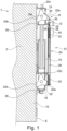
- Fig.1 shows a schematic representation of a self-climbing system for a concrete structure according to a preferred embodiment of the invention.
- the self-climbing system 1 has a climbing rail 10 and a climbing mechanism 12 that can be moved axially along the climbing rail.
- the climbing mechanism 12 has a first climbing head 14, a second climbing head 16 and a linear drive 18 connecting the first climbing head 14 to the second climbing head 16.
- the first climbing head 14 and the second climbing head 16 each have an adjusting element 20, 22 that can be adjusted between a climbing position K and a locking position R, in particular of the climbing mechanism 12.
- the adjusting element 20 of the first climbing head 14 and the adjusting element 22 of the second climbing head 16 are connected by a control rod 24.
- the outer tube 28 and the inner tube 30 or alternatively the shaft of the control rod 24 also have a spring element 32, in particular a spiral spring, at one end of the stroke.
- the spring element 32 initiates the actuation of the actuating element 20, 22 of the first climbing head 14 and/or the second climbing head 16.
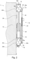
- Fig.2 shows a schematic representation of a self-climbing system for a concrete structure according to the preferred embodiment of the invention.
- the linear drive 18 is slightly further in the present representation than in Fig.1 extended so that the actuating element 20 of the first climbing head 14 is lifted off the locking block 26, but is still arranged in the locking position R.
- the actuating element 22 of the second climbing head 16 is still supported on a locking block 26 of the plurality of locking blocks.
- Fig.3 shows a schematic representation of a self-climbing system for a concrete structure according to the preferred embodiment of the invention.
- the linear drive 18 is a little further than in Fig.2 extended.
- the actuating element 20 was moved from the locking position R into the climbing position K.
- the climbing mechanism 12 is designed to move the actuating element 20 of the first climbing head, which is arranged in the climbing position, from the climbing position into the locking position R.
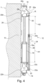
- Fig.5 shows a schematic representation of a self-climbing system for a concrete structure according to the preferred embodiment of the invention.
- the linear drive 18 is opposite the one in Fig.4 shown illustration, so that the adjusting element 20 of the first climbing head 14 now rests on a locking block 26.
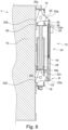
- the Fig. 1 to Fig. 9 The movement sequence of the self-climbing system 1 shown thus advantageously enables climbing both the climbing rail and a console (not shown in the figures).
- the adjusting element no longer rests on the locking block 26, but lies underneath it. If the representations are mirrored, the climbing of the rail can be shown.
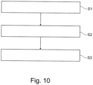
- the method comprises applying S3 to at least one of the actuating elements 20, 22 a torque D in predetermined positions 18a, 18b of the linear drive 18 by the control rod 24.
Landscapes
- Engineering & Computer Science (AREA)
- Architecture (AREA)
- Mechanical Engineering (AREA)
- Civil Engineering (AREA)
- Structural Engineering (AREA)
- General Engineering & Computer Science (AREA)
- Forms Removed On Construction Sites Or Auxiliary Members Thereof (AREA)
- Transmission Devices (AREA)
Claims (17)
- Système auto-grimpant (1) pour un corps structural en béton (2), comportant un rail de montée (10) et une unité de montée (12) axialement déplaçable le long du rail de montée (10), cette dernière comporte une première tête de montée (14), une seconde tête de montée (16) et un entraînement linéaire (18) reliant la première tête de montée (14) et la seconde tête de montée (16), dans lequel la première tête de montée (14) et la seconde tête de montée (16) comportent respectivement un élément de réglage (20, 22) réglable entre une position de montée (K) et une position de blocage (R), en particulier de l'unité de montée (12), caractérisé en ce que l'élément de réglage (20) de la première tête de montée (14) et l'élément de réglage (22) de la seconde tête de montée (16) sont reliés par une tige de commande (24), et en ce que la tige de commande (24) est conçue pour appliquer un couple (D) à au moins un des éléments de réglage (20, 22) dans des positions prédéterminées (18a, 18b) de l'entraînement linéaire (18).
- Système auto-grimpant selon la revendication 1, caractérisé en ce que, lors d'un passage sur un bloc de blocage (26) parmi une pluralité de blocs de blocage (26) agencés sur le rail de montée (10) provoqué par un mouvement axial de l'entraînement linéaire (18), l'élément de réglage (20) de la première tête de montée (14) et l'élément de réglage (22) de la seconde tête de montée (16) peuvent être déplacés de la position de blocage (R), dans laquelle l'élément de réglage (20, 22) est agencé, au moins dans certaines zones, dans le plan (E) du bloc de blocage (26), jusqu'à la position de montée (K), dans laquelle l'élément de réglage (20, 22) est agencé à l'extérieur du plan (E) du bloc de blocage (26).
- Système auto-grimpant selon la revendication 1 ou 2, caractérisé en ce que la tige de commande (24) comporte un tube extérieur (28) et un tube intérieur (30) pouvant être rentré et sorti du tube extérieur (18) ou un arbre, dans lequel lorsque l'entraînement linéaire (28) est déplacé jusqu'à une première position finale axiale (18a), en particulier jusqu'à une position entièrement rentrée ou sortie, la tige de commande (24) est conçue pour générer une impulsion de basculement afin de déplacer l'élément de réglage (20) de la première tête de montée (14) ou de la seconde tête de montée (16) agencé en position de montée (K), de la position de montée (K) à la position de blocage (R).
- Système auto-grimpant selon la revendication 3, caractérisé en ce qu'une course (H1) de l'entraînement linéaire (18) est sensiblement identique ou présente un écart allant jusqu'à 15 % par rapport à une course (H2) de la tige de commande (24), dans lequel lorsqu'une première position finale axiale (24a) de la tige de commande (24) est atteinte, l'unité de montée (12) est conçue pour déplacer l'élément de réglage (20) de la première tête de montée (14) ou de la seconde tête de montée (16) agencé en position de montée (K), de la position de montée (K) à la position de blocage (R).
- Système auto-grimpant selon l'une des revendications précédentes, caractérisé en ce que lorsque l'entraînement linéaire (14) est déplacé jusqu'à une seconde position finale axiale (18b), en particulier jusqu'à une position entièrement rentrée, la tige de commande (24) est conçue pour déplacer l'élément de réglage (20) de la première tête de montée (14) ou de la seconde tête de montée (16) agencé en position de montée (K), de la position de montée (K) à la position de blocage (R).
- Système auto-grimpant selon la revendication 4, caractérisé en ce que lorsque la seconde position finale axiale (24a) de la tige de commande (24) est atteinte, l'unité de montée (12) est conçue pour déplacer l'élément de réglage (20) de la première tête de montée (14) ou de la seconde tête de montée (16) agencé en position de montée (K), de la position de montée (K) à la position de blocage (R).
- Système auto-grimpant selon l'une des revendications précédentes, caractérisé en ce que l'élément de réglage (20) de la première tête de montée (14) et l'élément de réglage (22) de la seconde tête de montée (16) sont agencés sur leur axe de rotation (DA) sur la tête de montée (14, 16) respective, et dans lequel la tige de commande (24) sur l'élément de réglage (20, 22) respectif est agencée de manière excentrée par rapport à l'axe de rotation.
- Système auto-grimpant selon l'une des revendications précédentes, caractérisé en ce que l'unité de montée (12) est conçue de telle sorte que l'élément de réglage (20, 22) de la première tête de montée (14) ou de la seconde tête de montée (16) sur un bloc de blocage (26) agencé sur le rail de montée (22) est supporté lorsque l'unité de montée (12) fonctionne dans la position de blocage (R), et dans lequel l'autre élément de réglage (20, 22) peut être actionné par la tige de commande (24).
- Système auto-grimpant selon l'une des revendications 3, 4 et 6 ou, lorsque dépendante de la revendication 3, selon l'une des revendications 5, 7 et 8, caractérisé en ce que le tube extérieur (28) et le tube intérieur (30) ou l'arbre de la tige de commande (24) comporte un élément à ressort (32), en particulier un ressort hélicoïdal, sur une fin de course qui déclenche l'actionnement de l'élément de réglage (20, 22) de la première tête de montée (14) et/ou de la seconde tête de montée (16).
- Système auto-grimpant selon la revendication 9, caractérisé en ce que le tube intérieur (30) comporte, en particulier sur une fin de course, un filetage extérieur (34) au moins dans certaines zones, à l'extrémité duquel est agencé un écrou (36), dans lequel l'écrou (36) forme une butée qui vient en butée contre une contre-butée (38), en particulier une réduction de diamètre, du tube extérieur (28).
- Système auto-grimpant selon l'une des revendications précédentes, caractérisé en ce que la tige de commande (24) comporte une poignée (40) qui, lorsqu'elle est actionnée, en particulier par un utilisateur, est conçue pour déplacer l'élément de réglage (20, 22) de la première tête de montée (14) ou de la seconde tête de montée (16) entre la position de montée (K) et la position de blocage (R).
- Système auto-grimpant selon l'une des revendications précédentes, caractérisé en ce que l'entraînement linéaire est formé par un vérin de réglage qui comporte une tige de piston axialement réglable dans un cylindre, dans lequel la tige de piston est reliée, au niveau d'une partie d'extrémité axiale, à la première tête de montée (14), et dans lequel le cylindre est relié, au niveau d'une partie d'extrémité axiale, à la seconde tête de montée (16).
- Système auto-grimpant selon l'une des revendications précédentes, caractérisé en ce que l'élément de réglage (20) de la première tête de montée (14) et l'élément de réglage (22) de la seconde tête de montée (16) sont chacun sensiblement en forme d'étoile, dans lequel l'élément de réglage (20, 22) comporte un premier flanc (20a, 22a) aligné radialement, un deuxième flanc (20b, 22b) aligné radialement et un troisième flanc (20c, 22c) aligné radialement.
- Système auto-grimpant selon la revendication 13, caractérisé en ce que la tige de commande (24) est reliée au premier flanc (20a, 22a) de l'élément de réglage (20) de la première tête de montée (14) et de l'élément de réglage (22) de la seconde tête de montée (16), et dans lequel le deuxième flanc (20b, 22b) des éléments de réglage (20, 22) est conçu pour reposer sur le bloc de blocage (26) dans la position de blocage (R) de l'unité de montée (12).
- Procédé pour faire monter une unité de montée (12) sur un rail de montée (10) agencé sur un corps structural en béton (2), comportant les étapes consistant à :fournir (S1) une première tête de montée (14), une seconde tête de montée (16) et un entraînement linéaire (18) reliant la première tête de montée (14) et la seconde tête de montée (16) ;fournir (S2) la première tête de montée (14) et la seconde tête de montée (16) avec un élément de réglage (20, 22) respectivement réglable entre une position de montée (K) et une position de blocage (R), en particulier de l'unité de montée (12), dans lequel l'élément de réglage (20) de la première tête de montée (14) et l'élément de réglage (22) de la seconde tête de montée (16) sont reliés par une tige de commande (24) ; etappliquer, par l'intermédiaire de la tige de commande (24), un couple (D) à au moins un des éléments de réglage (20, 22) dans des positions prédéterminées (18a, 18b) de l'entraînement linéaire (18).
- Procédé selon la revendication 15, caractérisé en ce que, lors d'un passage sur un bloc de blocage (26) parmi une pluralité de blocs de blocage (26) agencés sur le rail de montée (10) provoqué par un mouvement axial de l'entraînement linéaire (18), l'élément de réglage (20) de la première tête de montée (14) et l'élément de réglage (22) de la seconde tête de montée (16) sont déplacés de la position de blocage (R), dans laquelle l'élément de réglage (20, 22) est agencé, au moins dans certaines zones, dans le plan (E) du bloc de blocage (26), jusqu'à la position de montée (K), dans laquelle l'élément de réglage (20, 22) est agencé à l'extérieur du plan (E) du bloc de blocage (26).
- Procédé selon la revendication 15 ou 16, caractérisé en ce que lorsque l'entraînement linéaire (14) est déplacé jusqu'à une première position finale axiale (18a), en particulier jusqu'à une position entièrement sortie, la tige de commande (24) génère une impulsion de basculement afin de déplacer l'élément de réglage (20) de la première tête de montée (14) ou de la seconde tête de montée (16) agencé en position de montée (K), de la position de montée (K) à la position de blocage (R).
Applications Claiming Priority (2)
| Application Number | Priority Date | Filing Date | Title |
|---|---|---|---|
| DE102020124646.3A DE102020124646A1 (de) | 2020-09-22 | 2020-09-22 | Selbstklettersystem für einen Betonbaukörper und Selbstkletterverfahren |
| PCT/EP2021/074401 WO2022063547A1 (fr) | 2020-09-22 | 2021-09-03 | Système auto-grimpant pour un corps structural en béton et procédé auto-grimpant |
Publications (2)
| Publication Number | Publication Date |
|---|---|
| EP4217552A1 EP4217552A1 (fr) | 2023-08-02 |
| EP4217552B1 true EP4217552B1 (fr) | 2024-07-17 |
Family
ID=77864548
Family Applications (1)
| Application Number | Title | Priority Date | Filing Date |
|---|---|---|---|
| EP21773507.5A Active EP4217552B1 (fr) | 2020-09-22 | 2021-09-03 | Système auto-grimpant pour un corps structural en béton et procédé auto-grimpant |
Country Status (5)
| Country | Link |
|---|---|
| US (1) | US20230358060A1 (fr) |
| EP (1) | EP4217552B1 (fr) |
| KR (1) | KR20230067633A (fr) |
| DE (1) | DE102020124646A1 (fr) |
| WO (1) | WO2022063547A1 (fr) |
Families Citing this family (3)
| Publication number | Priority date | Publication date | Assignee | Title |
|---|---|---|---|---|
| DE102019104548A1 (de) * | 2019-02-22 | 2020-08-27 | Peri Gmbh | Hubantrieb für ein schienengeführtes freivorbaugerät |
| DE102023134914A1 (de) * | 2023-12-13 | 2025-06-18 | Schwing Gmbh | Tragsäule |
| CN119933341B (zh) * | 2025-04-09 | 2025-06-06 | 上海建工一建集团有限公司 | 一种整体提升钢平台自爬升动力系统与方法 |
Family Cites Families (5)
| Publication number | Priority date | Publication date | Assignee | Title |
|---|---|---|---|---|
| DE4302197A1 (de) * | 1993-01-27 | 1994-07-28 | Peri Gmbh | Klettervorrichtung, insbesondere für ein Klettergerüst |
| ES2339442T3 (es) | 2003-11-27 | 2010-05-20 | Ulma C Y E, S. Coop. | Sistema trepador para encofrados, andamios y cargas en general. |
| KR100704720B1 (ko) * | 2006-05-19 | 2007-04-23 | 금강공업 주식회사 | 가설대 승강장치 및 이를 이용한 가설대 승강방법 |
| DE102007026020A1 (de) * | 2007-06-04 | 2008-12-11 | Doka Industrie Gmbh | Selbstklettersystem und Verfahren zum Betonieren eines Unterzugs und/oder Montieren eines Fertigteils mittels eines Selbstklettersystems |
| PL2995749T3 (pl) | 2014-09-10 | 2022-09-12 | Doka Gmbh | Sposób i urządzenie do obniżania elementu deskowania lub zabezpieczenia |
-
2020
- 2020-09-22 DE DE102020124646.3A patent/DE102020124646A1/de active Pending
-
2021
- 2021-09-03 EP EP21773507.5A patent/EP4217552B1/fr active Active
- 2021-09-03 KR KR1020237011101A patent/KR20230067633A/ko active Pending
- 2021-09-03 US US18/246,229 patent/US20230358060A1/en active Pending
- 2021-09-03 WO PCT/EP2021/074401 patent/WO2022063547A1/fr not_active Ceased
Also Published As
| Publication number | Publication date |
|---|---|
| US20230358060A1 (en) | 2023-11-09 |
| KR20230067633A (ko) | 2023-05-16 |
| EP4217552A1 (fr) | 2023-08-02 |
| WO2022063547A1 (fr) | 2022-03-31 |
| DE102020124646A1 (de) | 2022-03-24 |
Similar Documents
| Publication | Publication Date | Title |
|---|---|---|
| EP3827146B1 (fr) | Mécanisme de levage pour système grimpant guidé sur des rails et procede de levage d'un système grimpant | |
| EP0681635B1 (fr) | Dispositif grimpeur, notamment pour echafaudage grimpant | |
| EP3762566B1 (fr) | Procédé pour déplacer un coffrage de dalle, élément anti-tamponnage ainsi que coffrage de dalle, dispositif support et dispositif de déplacement par cycle présentant un tel élément anti-tamponnage | |
| EP3752692B1 (fr) | Système grimpant et procédé pour faire fonctionner un système grimpant | |
| EP4217552A1 (fr) | Système auto-grimpant pour un corps structural en béton et procédé auto-grimpant | |
| WO2020064423A1 (fr) | Dispositif de télescopage pour un échafaudage de coffrage | |
| EP3354829B1 (fr) | Dispositif d'actionnement pour véhicule automobile | |
| WO2014079628A1 (fr) | Dispositif de préhension destiné à manipuler des cages d'armature pour des segments de tour d'une éolienne | |
| EP0373617A2 (fr) | Echafaudage de déplacement susceptible d'être déplacé par sections sur un mur | |
| EP3146166B1 (fr) | Arbre à cames | |
| DE9408289U1 (de) | Teleskopierbarer Ausleger mit mehrstufigem Hydraulikzylinder | |
| DE102011077569A1 (de) | Trommel | |
| DE2140235A1 (de) | Anlage mit großen, rotierenden Bürsten zum Waschen von Fahrzeugen verschiedener ArL | |
| DE1579067B1 (de) | Drehbare Reifenaufbautrommel mit radial ein- und ausfahrbaren Trommelsegmenten | |
| WO1998054041A1 (fr) | Dispositif pour le verrouillage en positions extremes de pieces d'aiguille mobiles | |
| DE102023134914A1 (de) | Tragsäule | |
| EP0332801B1 (fr) | Appareil pour changer la forme de coupe d'ébauches de boites | |
| EP3919683B1 (fr) | Dispositif de raccordement | |
| EP0022121B1 (fr) | Charpente de soutien et de guidage pour des installations de coulée continue | |
| DE3607953C2 (fr) | ||
| DE2360532A1 (de) | Maschine zur herstellung von bewehrungskoerpern fuer betonrohre | |
| DE19947188C2 (de) | Ausziehtisch mit einem Tischgestell | |
| EP0488990A1 (fr) | Flèche télescopique entraînée par un seul cérin à vis | |
| DE2633022B1 (de) | Teleskopier-antriebs-einrichtung eines teleskopauslegers | |
| DE102015209872A1 (de) | Applikationsvorrichtung |
Legal Events
| Date | Code | Title | Description |
|---|---|---|---|
| STAA | Information on the status of an ep patent application or granted ep patent |
Free format text: STATUS: UNKNOWN |
|
| STAA | Information on the status of an ep patent application or granted ep patent |
Free format text: STATUS: THE INTERNATIONAL PUBLICATION HAS BEEN MADE |
|
| PUAI | Public reference made under article 153(3) epc to a published international application that has entered the european phase |
Free format text: ORIGINAL CODE: 0009012 |
|
| STAA | Information on the status of an ep patent application or granted ep patent |
Free format text: STATUS: REQUEST FOR EXAMINATION WAS MADE |
|
| 17P | Request for examination filed |
Effective date: 20230417 |
|
| AK | Designated contracting states |
Kind code of ref document: A1 Designated state(s): AL AT BE BG CH CY CZ DE DK EE ES FI FR GB GR HR HU IE IS IT LI LT LU LV MC MK MT NL NO PL PT RO RS SE SI SK SM TR |
|
| DAV | Request for validation of the european patent (deleted) | ||
| DAX | Request for extension of the european patent (deleted) | ||
| GRAP | Despatch of communication of intention to grant a patent |
Free format text: ORIGINAL CODE: EPIDOSNIGR1 |
|
| STAA | Information on the status of an ep patent application or granted ep patent |
Free format text: STATUS: GRANT OF PATENT IS INTENDED |
|
| INTG | Intention to grant announced |
Effective date: 20240314 |
|
| GRAS | Grant fee paid |
Free format text: ORIGINAL CODE: EPIDOSNIGR3 |
|
| GRAA | (expected) grant |
Free format text: ORIGINAL CODE: 0009210 |
|
| STAA | Information on the status of an ep patent application or granted ep patent |
Free format text: STATUS: THE PATENT HAS BEEN GRANTED |
|
| AK | Designated contracting states |
Kind code of ref document: B1 Designated state(s): AL AT BE BG CH CY CZ DE DK EE ES FI FR GB GR HR HU IE IS IT LI LT LU LV MC MK MT NL NO PL PT RO RS SE SI SK SM TR |
|
| REG | Reference to a national code |
Ref country code: CH Ref legal event code: EP |
|
| REG | Reference to a national code |
Ref country code: DE Ref legal event code: R096 Ref document number: 502021004428 Country of ref document: DE |
|
| REG | Reference to a national code |
Ref country code: IE Ref legal event code: FG4D Free format text: LANGUAGE OF EP DOCUMENT: GERMAN |
|
| REG | Reference to a national code |
Ref country code: LT Ref legal event code: MG9D |
|
| REG | Reference to a national code |
Ref country code: NL Ref legal event code: MP Effective date: 20240717 |
|
| PG25 | Lapsed in a contracting state [announced via postgrant information from national office to epo] |
Ref country code: PT Free format text: LAPSE BECAUSE OF FAILURE TO SUBMIT A TRANSLATION OF THE DESCRIPTION OR TO PAY THE FEE WITHIN THE PRESCRIBED TIME-LIMIT Effective date: 20241118 |
|
| PG25 | Lapsed in a contracting state [announced via postgrant information from national office to epo] |
Ref country code: NL Free format text: LAPSE BECAUSE OF FAILURE TO SUBMIT A TRANSLATION OF THE DESCRIPTION OR TO PAY THE FEE WITHIN THE PRESCRIBED TIME-LIMIT Effective date: 20240717 |
|
| PG25 | Lapsed in a contracting state [announced via postgrant information from national office to epo] |
Ref country code: PT Free format text: LAPSE BECAUSE OF FAILURE TO SUBMIT A TRANSLATION OF THE DESCRIPTION OR TO PAY THE FEE WITHIN THE PRESCRIBED TIME-LIMIT Effective date: 20241118 Ref country code: NL Free format text: LAPSE BECAUSE OF FAILURE TO SUBMIT A TRANSLATION OF THE DESCRIPTION OR TO PAY THE FEE WITHIN THE PRESCRIBED TIME-LIMIT Effective date: 20240717 |
|
| PG25 | Lapsed in a contracting state [announced via postgrant information from national office to epo] |
Ref country code: NO Free format text: LAPSE BECAUSE OF FAILURE TO SUBMIT A TRANSLATION OF THE DESCRIPTION OR TO PAY THE FEE WITHIN THE PRESCRIBED TIME-LIMIT Effective date: 20241017 |
|
| PG25 | Lapsed in a contracting state [announced via postgrant information from national office to epo] |
Ref country code: FI Free format text: LAPSE BECAUSE OF FAILURE TO SUBMIT A TRANSLATION OF THE DESCRIPTION OR TO PAY THE FEE WITHIN THE PRESCRIBED TIME-LIMIT Effective date: 20240717 Ref country code: GR Free format text: LAPSE BECAUSE OF FAILURE TO SUBMIT A TRANSLATION OF THE DESCRIPTION OR TO PAY THE FEE WITHIN THE PRESCRIBED TIME-LIMIT Effective date: 20241018 Ref country code: PL Free format text: LAPSE BECAUSE OF FAILURE TO SUBMIT A TRANSLATION OF THE DESCRIPTION OR TO PAY THE FEE WITHIN THE PRESCRIBED TIME-LIMIT Effective date: 20240717 |
|
| PG25 | Lapsed in a contracting state [announced via postgrant information from national office to epo] |
Ref country code: BG Free format text: LAPSE BECAUSE OF FAILURE TO SUBMIT A TRANSLATION OF THE DESCRIPTION OR TO PAY THE FEE WITHIN THE PRESCRIBED TIME-LIMIT Effective date: 20240717 |
|
| PG25 | Lapsed in a contracting state [announced via postgrant information from national office to epo] |
Ref country code: LV Free format text: LAPSE BECAUSE OF FAILURE TO SUBMIT A TRANSLATION OF THE DESCRIPTION OR TO PAY THE FEE WITHIN THE PRESCRIBED TIME-LIMIT Effective date: 20240717 |
|
| PG25 | Lapsed in a contracting state [announced via postgrant information from national office to epo] |
Ref country code: IS Free format text: LAPSE BECAUSE OF FAILURE TO SUBMIT A TRANSLATION OF THE DESCRIPTION OR TO PAY THE FEE WITHIN THE PRESCRIBED TIME-LIMIT Effective date: 20241117 |
|
| PG25 | Lapsed in a contracting state [announced via postgrant information from national office to epo] |
Ref country code: HR Free format text: LAPSE BECAUSE OF FAILURE TO SUBMIT A TRANSLATION OF THE DESCRIPTION OR TO PAY THE FEE WITHIN THE PRESCRIBED TIME-LIMIT Effective date: 20240717 |
|
| PG25 | Lapsed in a contracting state [announced via postgrant information from national office to epo] |
Ref country code: ES Free format text: LAPSE BECAUSE OF FAILURE TO SUBMIT A TRANSLATION OF THE DESCRIPTION OR TO PAY THE FEE WITHIN THE PRESCRIBED TIME-LIMIT Effective date: 20240717 Ref country code: RS Free format text: LAPSE BECAUSE OF FAILURE TO SUBMIT A TRANSLATION OF THE DESCRIPTION OR TO PAY THE FEE WITHIN THE PRESCRIBED TIME-LIMIT Effective date: 20241017 |
|
| PG25 | Lapsed in a contracting state [announced via postgrant information from national office to epo] |
Ref country code: RS Free format text: LAPSE BECAUSE OF FAILURE TO SUBMIT A TRANSLATION OF THE DESCRIPTION OR TO PAY THE FEE WITHIN THE PRESCRIBED TIME-LIMIT Effective date: 20241017 Ref country code: PL Free format text: LAPSE BECAUSE OF FAILURE TO SUBMIT A TRANSLATION OF THE DESCRIPTION OR TO PAY THE FEE WITHIN THE PRESCRIBED TIME-LIMIT Effective date: 20240717 Ref country code: NO Free format text: LAPSE BECAUSE OF FAILURE TO SUBMIT A TRANSLATION OF THE DESCRIPTION OR TO PAY THE FEE WITHIN THE PRESCRIBED TIME-LIMIT Effective date: 20241017 Ref country code: LV Free format text: LAPSE BECAUSE OF FAILURE TO SUBMIT A TRANSLATION OF THE DESCRIPTION OR TO PAY THE FEE WITHIN THE PRESCRIBED TIME-LIMIT Effective date: 20240717 Ref country code: IS Free format text: LAPSE BECAUSE OF FAILURE TO SUBMIT A TRANSLATION OF THE DESCRIPTION OR TO PAY THE FEE WITHIN THE PRESCRIBED TIME-LIMIT Effective date: 20241117 Ref country code: HR Free format text: LAPSE BECAUSE OF FAILURE TO SUBMIT A TRANSLATION OF THE DESCRIPTION OR TO PAY THE FEE WITHIN THE PRESCRIBED TIME-LIMIT Effective date: 20240717 Ref country code: GR Free format text: LAPSE BECAUSE OF FAILURE TO SUBMIT A TRANSLATION OF THE DESCRIPTION OR TO PAY THE FEE WITHIN THE PRESCRIBED TIME-LIMIT Effective date: 20241018 Ref country code: FI Free format text: LAPSE BECAUSE OF FAILURE TO SUBMIT A TRANSLATION OF THE DESCRIPTION OR TO PAY THE FEE WITHIN THE PRESCRIBED TIME-LIMIT Effective date: 20240717 Ref country code: ES Free format text: LAPSE BECAUSE OF FAILURE TO SUBMIT A TRANSLATION OF THE DESCRIPTION OR TO PAY THE FEE WITHIN THE PRESCRIBED TIME-LIMIT Effective date: 20240717 Ref country code: BG Free format text: LAPSE BECAUSE OF FAILURE TO SUBMIT A TRANSLATION OF THE DESCRIPTION OR TO PAY THE FEE WITHIN THE PRESCRIBED TIME-LIMIT Effective date: 20240717 |
|
| PG25 | Lapsed in a contracting state [announced via postgrant information from national office to epo] |
Ref country code: RO Free format text: LAPSE BECAUSE OF FAILURE TO SUBMIT A TRANSLATION OF THE DESCRIPTION OR TO PAY THE FEE WITHIN THE PRESCRIBED TIME-LIMIT Effective date: 20240717 Ref country code: SM Free format text: LAPSE BECAUSE OF FAILURE TO SUBMIT A TRANSLATION OF THE DESCRIPTION OR TO PAY THE FEE WITHIN THE PRESCRIBED TIME-LIMIT Effective date: 20240717 Ref country code: DK Free format text: LAPSE BECAUSE OF FAILURE TO SUBMIT A TRANSLATION OF THE DESCRIPTION OR TO PAY THE FEE WITHIN THE PRESCRIBED TIME-LIMIT Effective date: 20240717 |
|
| REG | Reference to a national code |
Ref country code: DE Ref legal event code: R097 Ref document number: 502021004428 Country of ref document: DE |
|
| PG25 | Lapsed in a contracting state [announced via postgrant information from national office to epo] |
Ref country code: MC Free format text: LAPSE BECAUSE OF FAILURE TO SUBMIT A TRANSLATION OF THE DESCRIPTION OR TO PAY THE FEE WITHIN THE PRESCRIBED TIME-LIMIT Effective date: 20240717 Ref country code: EE Free format text: LAPSE BECAUSE OF FAILURE TO SUBMIT A TRANSLATION OF THE DESCRIPTION OR TO PAY THE FEE WITHIN THE PRESCRIBED TIME-LIMIT Effective date: 20240717 |
|
| PG25 | Lapsed in a contracting state [announced via postgrant information from national office to epo] |
Ref country code: CZ Free format text: LAPSE BECAUSE OF FAILURE TO SUBMIT A TRANSLATION OF THE DESCRIPTION OR TO PAY THE FEE WITHIN THE PRESCRIBED TIME-LIMIT Effective date: 20240717 |
|
| PG25 | Lapsed in a contracting state [announced via postgrant information from national office to epo] |
Ref country code: SK Free format text: LAPSE BECAUSE OF FAILURE TO SUBMIT A TRANSLATION OF THE DESCRIPTION OR TO PAY THE FEE WITHIN THE PRESCRIBED TIME-LIMIT Effective date: 20240717 |
|
| REG | Reference to a national code |
Ref country code: CH Ref legal event code: PL |
|
| PG25 | Lapsed in a contracting state [announced via postgrant information from national office to epo] |
Ref country code: LU Free format text: LAPSE BECAUSE OF NON-PAYMENT OF DUE FEES Effective date: 20240903 |
|
| PLBE | No opposition filed within time limit |
Free format text: ORIGINAL CODE: 0009261 |
|
| STAA | Information on the status of an ep patent application or granted ep patent |
Free format text: STATUS: NO OPPOSITION FILED WITHIN TIME LIMIT |
|
| 26N | No opposition filed |
Effective date: 20250422 |
|
| REG | Reference to a national code |
Ref country code: BE Ref legal event code: MM Effective date: 20240930 |
|
| PG25 | Lapsed in a contracting state [announced via postgrant information from national office to epo] |
Ref country code: BE Free format text: LAPSE BECAUSE OF NON-PAYMENT OF DUE FEES Effective date: 20240930 |
|
| PG25 | Lapsed in a contracting state [announced via postgrant information from national office to epo] |
Ref country code: FR Free format text: LAPSE BECAUSE OF NON-PAYMENT OF DUE FEES Effective date: 20240917 |
|
| PG25 | Lapsed in a contracting state [announced via postgrant information from national office to epo] |
Ref country code: CH Free format text: LAPSE BECAUSE OF NON-PAYMENT OF DUE FEES Effective date: 20240930 |
|
| PG25 | Lapsed in a contracting state [announced via postgrant information from national office to epo] |
Ref country code: IE Free format text: LAPSE BECAUSE OF NON-PAYMENT OF DUE FEES Effective date: 20240903 |
|
| PG25 | Lapsed in a contracting state [announced via postgrant information from national office to epo] |
Ref country code: SE Free format text: LAPSE BECAUSE OF FAILURE TO SUBMIT A TRANSLATION OF THE DESCRIPTION OR TO PAY THE FEE WITHIN THE PRESCRIBED TIME-LIMIT Effective date: 20240717 |
|
| PGFP | Annual fee paid to national office [announced via postgrant information from national office to epo] |
Ref country code: DE Payment date: 20250917 Year of fee payment: 5 |
|
| PGFP | Annual fee paid to national office [announced via postgrant information from national office to epo] |
Ref country code: AT Payment date: 20251020 Year of fee payment: 5 |
|
| PG25 | Lapsed in a contracting state [announced via postgrant information from national office to epo] |
Ref country code: IT Free format text: LAPSE BECAUSE OF NON-PAYMENT OF DUE FEES Effective date: 20240903 |
|
| PG25 | Lapsed in a contracting state [announced via postgrant information from national office to epo] |
Ref country code: CY Free format text: LAPSE BECAUSE OF FAILURE TO SUBMIT A TRANSLATION OF THE DESCRIPTION OR TO PAY THE FEE WITHIN THE PRESCRIBED TIME-LIMIT; INVALID AB INITIO Effective date: 20210903 |
|
| PG25 | Lapsed in a contracting state [announced via postgrant information from national office to epo] |
Ref country code: HU Free format text: LAPSE BECAUSE OF FAILURE TO SUBMIT A TRANSLATION OF THE DESCRIPTION OR TO PAY THE FEE WITHIN THE PRESCRIBED TIME-LIMIT; INVALID AB INITIO Effective date: 20210903 |
|
| PG25 | Lapsed in a contracting state [announced via postgrant information from national office to epo] |
Ref country code: IT Free format text: LAPSE BECAUSE OF NON-PAYMENT OF DUE FEES Effective date: 20240903 |
|
| PGFP | Annual fee paid to national office [announced via postgrant information from national office to epo] |
Ref country code: IT Payment date: 20240930 Year of fee payment: 4 |
|
| PGRI | Patent reinstated in contracting state [announced from national office to epo] |
Ref country code: IT Effective date: 20240930 |