EP4217552B1 - Self-climbing system for a concrete structural body, and self-climbing method - Google Patents
Self-climbing system for a concrete structural body, and self-climbing method Download PDFInfo
- Publication number
- EP4217552B1 EP4217552B1 EP21773507.5A EP21773507A EP4217552B1 EP 4217552 B1 EP4217552 B1 EP 4217552B1 EP 21773507 A EP21773507 A EP 21773507A EP 4217552 B1 EP4217552 B1 EP 4217552B1
- Authority
- EP
- European Patent Office
- Prior art keywords
- climbing
- head
- actuating element
- control rod
- self
- Prior art date
- Legal status (The legal status is an assumption and is not a legal conclusion. Google has not performed a legal analysis and makes no representation as to the accuracy of the status listed.)
- Active
Links
Images




Classifications
-
- E—FIXED CONSTRUCTIONS
- E04—BUILDING
- E04G—SCAFFOLDING; FORMS; SHUTTERING; BUILDING IMPLEMENTS OR AIDS, OR THEIR USE; HANDLING BUILDING MATERIALS ON THE SITE; REPAIRING, BREAKING-UP OR OTHER WORK ON EXISTING BUILDINGS
- E04G11/00—Forms, shutterings, or falsework for making walls, floors, ceilings, or roofs
- E04G11/06—Forms, shutterings, or falsework for making walls, floors, ceilings, or roofs for walls, e.g. curved end panels for wall shutterings; filler elements for wall shutterings; shutterings for vertical ducts
- E04G11/20—Movable forms; Movable forms for moulding cylindrical, conical or hyperbolical structures; Templates serving as forms for positioning blocks or the like
- E04G11/22—Sliding forms raised continuously or step-by-step and being in contact with the poured concrete during raising and which are not anchored in the hardened concrete; Arrangements of lifting means therefor
- E04G11/24—Construction of lifting jacks or climbing rods for sliding forms
-
- E—FIXED CONSTRUCTIONS
- E04—BUILDING
- E04G—SCAFFOLDING; FORMS; SHUTTERING; BUILDING IMPLEMENTS OR AIDS, OR THEIR USE; HANDLING BUILDING MATERIALS ON THE SITE; REPAIRING, BREAKING-UP OR OTHER WORK ON EXISTING BUILDINGS
- E04G11/00—Forms, shutterings, or falsework for making walls, floors, ceilings, or roofs
- E04G11/06—Forms, shutterings, or falsework for making walls, floors, ceilings, or roofs for walls, e.g. curved end panels for wall shutterings; filler elements for wall shutterings; shutterings for vertical ducts
- E04G11/20—Movable forms; Movable forms for moulding cylindrical, conical or hyperbolical structures; Templates serving as forms for positioning blocks or the like
- E04G11/28—Climbing forms, i.e. forms which are not in contact with the poured concrete during lifting from layer to layer and which are anchored in the hardened concrete
-
- F—MECHANICAL ENGINEERING; LIGHTING; HEATING; WEAPONS; BLASTING
- F16—ENGINEERING ELEMENTS AND UNITS; GENERAL MEASURES FOR PRODUCING AND MAINTAINING EFFECTIVE FUNCTIONING OF MACHINES OR INSTALLATIONS; THERMAL INSULATION IN GENERAL
- F16M—FRAMES, CASINGS OR BEDS OF ENGINES, MACHINES OR APPARATUS, NOT SPECIFIC TO ENGINES, MACHINES OR APPARATUS PROVIDED FOR ELSEWHERE; STANDS; SUPPORTS
- F16M13/00—Other supports for positioning apparatus or articles; Means for steadying hand-held apparatus or articles
- F16M13/02—Other supports for positioning apparatus or articles; Means for steadying hand-held apparatus or articles for supporting on, or attaching to, an object, e.g. tree, gate, window-frame, cycle
- F16M13/022—Other supports for positioning apparatus or articles; Means for steadying hand-held apparatus or articles for supporting on, or attaching to, an object, e.g. tree, gate, window-frame, cycle repositionable
Definitions
- the invention relates to a self-climbing system for a concrete structure, with a climbing rail and a climbing mechanism that can be moved axially along the climbing rail, which has a first climbing head, a second climbing head and a linear drive connecting the first climbing head to the second climbing head, wherein the first climbing head and the second climbing head each have an actuating element that can be adjusted between a climbing position and a locking position, in particular of the climbing mechanism, wherein the actuating element of the first climbing head and the actuating element of the second climbing head are connected by a control rod, and wherein the control rod is designed to apply a torque to at least one of the actuating elements in predetermined positions of the linear drive.
- the method further comprises applying a torque to at least one of the actuating elements in predetermined positions of the linear drive by the control rod.
- One idea of the present invention is to dispense with the control gates on the climbing rail by controlling the adjusting elements using the control rod. This means that less damage occurs and the actuation of the locking mechanism functions independently of friction with fewer malfunctions. Furthermore, the restoring forces are lower with this type of actuation and place less strain on the gate bearing.
- the climbing rails are easier and cheaper to manufacture because control gates are no longer required.
- the actuating element of the first climbing head and the actuating element of the second climbing head can be moved from the locking position, in which the actuating element is arranged at least partially in the plane of the locking block, into the climbing position, in which the actuating element is arranged outside the plane of the locking block, when a locking block of a plurality of locking blocks arranged on the climbing rail is passed over by the axial movement of the linear drive.
- the interaction of the at least one actuating element with the locking block arranged on the climbing rail thus advantageously causes the respective actuating element to switch between the climbing position and the locking position.
- the control rod when the linear drive is moved into a second axial end position, in particular into a fully retracted position, the control rod is designed to move the actuating element of the first climbing head or the second climbing head arranged in the climbing position from the climbing position into the locking position.
- the climbing mechanism is designed to move the actuating element of the first climbing head or the second climbing head arranged in the climbing position from the climbing position into the locking position when the second axial end position of the control rod is reached.
- the control rod can thus advantageously be moved along with a movement of the linear drive, with the control rod only carrying out its control effect at the respective end positions of the stroke of the linear drive.
- the actuating element of the first climbing head and the actuating element of the second climbing head are arranged on a rotation axis on the respective climbing head, and wherein the control rod on the respective actuating element is arranged eccentrically to the rotation axis. Due to the eccentric arrangement or connection of the control rod to the respective actuating element, the control rod can thus advantageously carry out its control effect of the actuating element.
- the inner tube in particular at the stroke end, has at least in sections an external thread, at the end of which a nut is arranged, wherein the nut forms a stop which strikes a counter-stop, in particular a diameter reduction, of the outer tube.
- an end stop of the head tube that can be adjusted by the nut can be advantageously provided.
- the actuating element of the first climbing head and the actuating element of the second climbing head are moved from the locking position, in which the actuating element is arranged at least in sections in the plane of the locking block, to the climbing position, in which the actuating element is arranged outside the plane of the locking block, when a locking block of a plurality of locking blocks arranged on the climbing rail is passed over by the axial movement of the linear drive.
- the interaction of the at least one actuating element with the locking block arranged on the climbing rail thus advantageously causes the respective actuating element to switch between the climbing position and the locking position.
- control rod generates a switching pulse when the linear drive is moved into a first axial end position, in particular into a fully retracted or extended position, in order to move the actuating element of the first climbing head or the second climbing head arranged in the climbing position from the climbing position into the
- the control rod thus advantageously enables a respective actuating element to be set or positioned in the locking position.
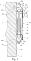
- Fig.1 shows a schematic representation of a self-climbing system for a concrete structure according to a preferred embodiment of the invention.
- the self-climbing system 1 has a climbing rail 10 and a climbing mechanism 12 that can be moved axially along the climbing rail.
- the climbing mechanism 12 has a first climbing head 14, a second climbing head 16 and a linear drive 18 connecting the first climbing head 14 to the second climbing head 16.
- the first climbing head 14 and the second climbing head 16 each have an adjusting element 20, 22 that can be adjusted between a climbing position K and a locking position R, in particular of the climbing mechanism 12.
- the adjusting element 20 of the first climbing head 14 and the adjusting element 22 of the second climbing head 16 are connected by a control rod 24.
- the outer tube 28 and the inner tube 30 or alternatively the shaft of the control rod 24 also have a spring element 32, in particular a spiral spring, at one end of the stroke.
- the spring element 32 initiates the actuation of the actuating element 20, 22 of the first climbing head 14 and/or the second climbing head 16.
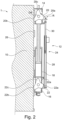
- Fig.2 shows a schematic representation of a self-climbing system for a concrete structure according to the preferred embodiment of the invention.
- the linear drive 18 is slightly further in the present representation than in Fig.1 extended so that the actuating element 20 of the first climbing head 14 is lifted off the locking block 26, but is still arranged in the locking position R.
- the actuating element 22 of the second climbing head 16 is still supported on a locking block 26 of the plurality of locking blocks.
- Fig.3 shows a schematic representation of a self-climbing system for a concrete structure according to the preferred embodiment of the invention.
- the linear drive 18 is a little further than in Fig.2 extended.
- the actuating element 20 was moved from the locking position R into the climbing position K.
- the climbing mechanism 12 is designed to move the actuating element 20 of the first climbing head, which is arranged in the climbing position, from the climbing position into the locking position R.
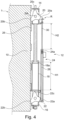
- Fig.5 shows a schematic representation of a self-climbing system for a concrete structure according to the preferred embodiment of the invention.
- the linear drive 18 is opposite the one in Fig.4 shown illustration, so that the adjusting element 20 of the first climbing head 14 now rests on a locking block 26.
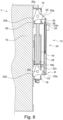
- the Fig. 1 to Fig. 9 The movement sequence of the self-climbing system 1 shown thus advantageously enables climbing both the climbing rail and a console (not shown in the figures).
- the adjusting element no longer rests on the locking block 26, but lies underneath it. If the representations are mirrored, the climbing of the rail can be shown.
- the method comprises applying S3 to at least one of the actuating elements 20, 22 a torque D in predetermined positions 18a, 18b of the linear drive 18 by the control rod 24.
Landscapes
- Engineering & Computer Science (AREA)
- Architecture (AREA)
- Mechanical Engineering (AREA)
- Civil Engineering (AREA)
- Structural Engineering (AREA)
- General Engineering & Computer Science (AREA)
- Forms Removed On Construction Sites Or Auxiliary Members Thereof (AREA)
- Transmission Devices (AREA)
Description
Die vorliegende Erfindung betrifft ein Selbstklettersystem für einen Betonbaukörper, mit einer Kletterschiene und einem entlang der Kletterschiene axial verfahrbaren Kletterwerk.The present invention relates to a self-climbing system for a concrete structure, with a climbing rail and a climbing mechanism that can be moved axially along the climbing rail.
Die vorliegende Erfindung betrifft des Weiteren ein Verfahren zum Klettern eines Kletterwerks an einer an einem Betonbaukörper angeordneten Kletterschiene.The present invention further relates to a method for climbing a climbing structure on a climbing rail arranged on a concrete structure.
Bei automatischen Selbstklettersystemen ist der Klettermechanismus in der Lage, sowohl eine Kletterschiene nach oben zu klettern als auch ein mit dem Klettermechanismus verbindbares Klettergerüst nach oben zu klettern. Mithilfe eines schaltbaren Klettermechanismus werden zunächst die Kletterschienen nach oben in den frischen Betonierabschnitt geklettert, zwischen Wand und Schalung verfahren und anschließend das Traggerüst mit Kletterwerk nach oben geklettert.In automatic self-climbing systems, the climbing mechanism is able to climb up a climbing rail as well as a climbing frame that can be connected to the climbing mechanism. With the help of a switchable climbing mechanism, the climbing rails are first climbed up into the freshly poured concrete section, moved between the wall and the formwork, and then the supporting frame with climbing mechanism is climbed up.
Bei einem Klettern der Kletterschiene sitzt ein Stellelement eines Kletterkopfes unter einem Rastklotz der Kletterschiene. Beim Klettern des Traggerüstes sitzt das Stellelement des Kletterkopfes auf einem Rastklotz der Kletterschiene auf. Beim Fahren in Endstellung werden Nocken in den Kletterköpfen über Schaltkulissen auf der Kletterschiene geschalten und nehmen dabei die Stellelemente mit, die dann je nach Einstellung wieder auf bzw. unter den Rastklötzen der Kletterschiene einrasten.When climbing the climbing rail, an adjusting element of a climbing head sits under a locking block on the climbing rail. When climbing the support structure, the adjusting element of the climbing head sits on a locking block on the climbing rail. When moving to the end position, cams in the climbing heads are switched via switching gates on the climbing rail and take the adjusting elements with them, which then lock back into place on or under the locking blocks on the climbing rail, depending on the setting.
Ein Hydraulikaggregat besitzt eine Steuerung, mit der die Zylinder aus- und eingefahren werden können. Damit das Traggerüst nach oben geklettert werden kann, muss die Schiene bereits vorher nach oben geklettert worden sein und ortsfest fixiert werden.A hydraulic unit has a control system that allows the cylinders to be extended and retracted. In order for the support structure to be climbed upwards, the rail must have already been climbed upwards and fixed in place.
Nachteilhaft an dieser Lösung ist, dass die Kletterschiene eine Vielzahl von Schaltkulissen aufweisen muss, um die Schaltvorgänge zum Positionieren der Stellelemente der jeweiligen Kletterköpfe einzuleiten.The disadvantage of this solution is that the climbing rail must have a large number of switching gates in order to initiate the switching processes for positioning the actuating elements of the respective climbing heads.
Die Verbindung zwischen dem Linearantrieb und der Tragschiene ist durch im Abstand voneinander angeordneten Kletterköpfen hergestellt.The connection between the linear drive and the support rail is made by climbing heads arranged at a distance from each other.
Ein Sperrglied wird hierbei bei der Relativbewegung in einer Richtung über den Sperrnocken hinweggehoben, in der anderen Bewegungsrichtung läuft dieses auf die Sperrnocke auf, sodass der eine Kletterkopf diese Relativbewegung sperrend mit der Tragschiene formschlüssig verbunden ist, während am anderen Kletterkopf eine die Sperrnocken überwindende Relativbewegung stattfindet.During the relative movement in one direction, a locking member is lifted over the locking cam, in the other direction of movement it runs onto the locking cam, so that one climbing head is positively connected to the support rail, blocking this relative movement, while a relative movement overcoming the locking cam takes place on the other climbing head.
Demzufolge besteht ein Bedarf, bestehende Selbstklettersysteme und Verfahren dahingehend zu verbessern, ein einfacheres Konzept zum Schalten von Stellelementen bei automatischen Klettersystemen bereitzustellen, welches zudem fehlerunanfälliger ist.Consequently, there is a need to improve existing self-climbing systems and methods to provide a simpler concept for switching actuators in automatic climbing systems, which is also less prone to errors.
Es ist daher Aufgabe der Erfindung, ein Selbstklettersystem und ein entsprechendes Verfahren anzugeben, welche ein vereinfachtes, fehlerunanfälligeres Schalten von Stellelementen bei automatischen Klettersystemen ermöglichen.It is therefore an object of the invention to provide a self-climbing system and a corresponding method which enable a simplified, less error-prone switching of control elements in automatic climbing systems.
Die Aufgabe wird erfindungsgemäß gelöst durch ein Selbstklettersystem für einen Betonbaukörper mit einer Kletterschiene und einem entlang der Kletterschiene axial verfahrbaren Kletterwerk nach Patentanspruch 1 sowie ein Verfahren zum Klettern eines Kletterwerks an einer an einem Betonbaukörper angeordneten Kletterschiene nach Patentanspruch 15.The object is achieved according to the invention by a self-climbing system for a concrete structure with a climbing rail and a climbing device that can be moved axially along the climbing rail according to
Die Erfindung betrifft ein Selbstklettersystem für einen Betonbaukörper, mit einer Kletterschiene und einem entlang der Kletterschiene axial verfahrbaren Kletterwerk, welches einen ersten Kletterkopf, einen zweiten Kletterkopf und einen den ersten Kletterkopf mit dem zweiten Kletterkopf verbindenden Linearantrieb aufweist, wobei der erste Kletterkopf und der zweite Kletterkopf jeweils ein zwischen einer Kletterstellung und einer Raststellung, insbesondere des Kletterwerks, stellbares Stellelement aufweisen, wobei das Stellelement des ersten Kletterkopfes und das Stellelement des zweiten Kletterkopfes durch eine Steuerstange verbunden sind, und wobei die Steuerstange dazu ausgebildet ist, in vorgegebenen Positionen des Linearantriebs zumindest eines der Stellelemente mit einem Drehmoment zu beaufschlagen.The invention relates to a self-climbing system for a concrete structure, with a climbing rail and a climbing mechanism that can be moved axially along the climbing rail, which has a first climbing head, a second climbing head and a linear drive connecting the first climbing head to the second climbing head, wherein the first climbing head and the second climbing head each have an actuating element that can be adjusted between a climbing position and a locking position, in particular of the climbing mechanism, wherein the actuating element of the first climbing head and the actuating element of the second climbing head are connected by a control rod, and wherein the control rod is designed to apply a torque to at least one of the actuating elements in predetermined positions of the linear drive.
Die Erfindung betrifft des Weiteren ein Verfahren zum Klettern eines Kletterwerks an einer an einem Betonbaukörper angeordneten Kletterschiene. Das Verfahren umfasst ein Bereitstellen eines ersten Kletterkopfes, eines zweiten Kletterkopfes und eines den ersten Kletterkopf mit dem zweiten Kletterkopf verbindenden Linearantriebs.The invention further relates to a method for climbing a climbing structure on a climbing rail arranged on a concrete structure. The method comprises providing a first climbing head, a second climbing head and a linear drive connecting the first climbing head to the second climbing head.
Das Verfahren umfasst des Weiteren ein Bereitstellen des ersten Kletterkopfes und des zweiten Kletterkopfes mit jeweils einem zwischen einer Kletterstellung und einer Raststellung, insbesondere des Kletterwerks, stellbaren Stellelement, wobei das Stellelement des ersten Kletterkopfes und das Stellelement des zweiten Kletterkopfes durch eine Steuerstange verbunden sind.The method further comprises providing the first climbing head and the second climbing head, each with an adjusting element that can be adjusted between a climbing position and a locking position, in particular of the climbing mechanism, wherein the adjusting element of the first climbing head and the adjusting element of the second climbing head are connected by a control rod.
Das Verfahren umfasst darüber hinaus ein Beaufschlagen zumindest eines der Stellelemente mit einem Drehmoment in vorgegebenen Positionen des Linearantriebs durch die Steuerstange.The method further comprises applying a torque to at least one of the actuating elements in predetermined positions of the linear drive by the control rod.
Eine Idee der vorliegenden Erfindung ist es, durch die Steuerung der Stellelemente mittels der Steuerstange auf die Steuerkulissen an der Kletterschiene zu verzichten. Es treten somit weniger Beschädigungen auf und die Betätigung des Rastmechanismus funktioniert reibungsunabhängig mit geringeren Fehlfunktionen. Ferner sind die Rückstellkräfte bei dieser Betätigungsart geringer und belasten die Kulissenlagerung weniger.One idea of the present invention is to dispense with the control gates on the climbing rail by controlling the adjusting elements using the control rod. This means that less damage occurs and the actuation of the locking mechanism functions independently of friction with fewer malfunctions. Furthermore, the restoring forces are lower with this type of actuation and place less strain on the gate bearing.
Zudem sind die Kletterschienen aufgrund nicht mehr benötigter Steuerkulissen einfacher und günstiger zu fertigen.In addition, the climbing rails are easier and cheaper to manufacture because control gates are no longer required.
Darüber hinaus ist die erfindungsgemäße Lösung ebenfalls in Kombination mit existierenden Kletterschienen anwendbar, mit welchen das erfindungsgemäße Kletterwerk kompatibel ist. Durch die erfindungsgemäße Lösung ergeben sich somit in vorteilhafter Weise deutlich weniger Verschleißerscheinungen an Kletterwerk und Kletterschiene.Furthermore, the solution according to the invention can also be used in combination with existing climbing rails with which the climbing structure according to the invention is compatible. The solution according to the invention thus advantageously results in significantly less signs of wear on the climbing structure and climbing rail.
Weitere Ausführungsformen der vorliegenden Erfindung sind Gegenstand der weiteren Unteransprüche und der nachfolgenden Beschreibung unter Bezugnahme auf die Figuren.Further embodiments of the present invention are the subject of the further subclaims and the following description with reference to the figures.
Gemäß einer bevorzugten Weiterbildung ist vorgesehen, dass das Stellelement des ersten Kletterkopfes und das Stellelement des zweiten Kletterkopfes bei durch Axialbewegung des Linearantriebs bedingten Überfahrens eines Rastklotzes einer Mehrzahl von auf der Kletterschiene angeordneten Rastklötzen von der Raststellung, in welcher das Stellelement zumindest abschnittsweise in der Ebene des Rastklotzes angeordnet ist, in die Kletterstellung, in welcher das Stellelement außerhalb der Ebene des Rastklotzes angeordnet ist, bewegbar ist. Das Zusammenwirken des zumindest einen Stellelements mit dem auf der Kletterschiene angeordneten Rastklotz bewirkt somit in vorteilhafter Weise ein Schalten des jeweiligen Stellelements zwischen Kletterstellung und Raststellung.According to a preferred development, it is provided that the actuating element of the first climbing head and the actuating element of the second climbing head can be moved from the locking position, in which the actuating element is arranged at least partially in the plane of the locking block, into the climbing position, in which the actuating element is arranged outside the plane of the locking block, when a locking block of a plurality of locking blocks arranged on the climbing rail is passed over by the axial movement of the linear drive. The interaction of the at least one actuating element with the locking block arranged on the climbing rail thus advantageously causes the respective actuating element to switch between the climbing position and the locking position.
Gemäß einer weiteren bevorzugten Weiterbildung ist vorgesehen, dass die Steuerstange ein Außenrohr und ein aus dem Außenrohr ein- und ausfahrbares Innenrohr oder eine Welle aufweist, wobei die Steuerstange bei Bewegen des Linearantriebs in eine erste axiale Endposition, insbesondere in eine vollständig ausgefahrene Position, dazu ausgebildet ist, einen Schaltimpuls zu erzeugen um das in Kletterstellung angeordnete Stellelement des ersten Kletterkopfes oder des zweiten Kletterkopfes von der Kletterstellung in die Raststellung zu bewegen.According to a further preferred development, it is provided that the control rod has an outer tube and an inner tube or a shaft that can be extended and retracted from the outer tube, wherein the control rod is designed to generate a switching pulse when the linear drive is moved into a first axial end position, in particular into a fully extended position, in order to move the actuating element of the first climbing head or the second climbing head arranged in the climbing position from the climbing position into the locking position.
Die Steuerstange ermöglicht somit in vorteilhafter Weise ein Einstellen bzw. Positionieren eines jeweiligen Stellelements in die Raststellung.The control rod thus advantageously enables a respective actuating element to be set or positioned in the locking position.
Gemäß einer weiteren bevorzugten Weiterbildung ist vorgesehen, dass ein Hub des Linearantriebs im Wesentlichen identisch oder mit einer Abweichung von bis zu 15% zu einem Hub der Steuerstange ist, wobei das Kletterwerk bei Erreichen einer ersten axialen Endposition der Steuerstange dazu ausgebildet ist, das in Kletterstellung angeordnete Stellelement des ersten Kletterkopfes oder des zweiten Kletterkopfes von der Kletterstellung in die Raststellung zu bewegen. Die Steuerstange kann somit in vorteilhafter Weise bei einer Bewegung des Linearantriebs mitbewegt werden, wobei die Steuerstange ihre Steuerwirkung lediglich an jeweiligen Endpositionen des Hubs des Linearantriebs durchführt.According to a further preferred development, it is provided that a stroke of the linear drive is essentially identical to or with a deviation of up to 15% from a stroke of the control rod, wherein the climbing mechanism is designed to move the actuating element of the first climbing head or the second climbing head arranged in the climbing position from the climbing position to the locking position when a first axial end position of the control rod is reached. The control rod can thus advantageously be moved along with a movement of the linear drive, wherein the control rod only carries out its control effect at the respective end positions of the stroke of the linear drive.
Gemäß einer weiteren bevorzugten Weiterbildung ist vorgesehen, dass die Steuerstange bei Bewegen des Linearantriebs in eine zweite axiale Endposition, insbesondere in eine vollständig eingefahrene Position, dazu ausgebildet ist, das in Kletterstellung angeordnete Stellelement des ersten Kletterkopfes oder des zweiten Kletterkopfes von der Kletterstellung in die Raststellung zu bewegen.According to a further preferred development, it is provided that when the linear drive is moved into a second axial end position, in particular into a fully retracted position, the control rod is designed to move the actuating element of the first climbing head or the second climbing head arranged in the climbing position from the climbing position into the locking position.
Die Steuerstange weist somit in vorteilhafter Weise sowohl in der ersten axialen Endposition als auch in der zweiten axialen Endposition des Steuerzylinders eine entsprechende Stellwirkung zum Verstellen des jeweiligen Kletterkopfes von der Kletterstellung in die Raststellung auf.The control rod thus advantageously has a corresponding adjusting effect for adjusting the respective climbing head from the climbing position to the locking position.
Gemäß einer weiteren bevorzugten Weiterbildung ist vorgesehen, dass das Kletterwerk bei Erreichen der zweiten axialen Endposition der Steuerstange dazu ausgebildet ist, das in Kletterstellung angeordnete Stellelement des ersten Kletterkopfes oder des zweiten Kletterkopfes von der Kletterstellung in die Raststellung zu bewegen. Die Steuerstange kann somit in vorteilhafter Weise bei einer Bewegung des Linearantriebs mitbewegt werden, wobei die Steuerstange ihre Steuerwirkung lediglich an jeweiligen Endpositionen des Hubs des Linearantriebs durchführt.According to a further preferred development, it is provided that the climbing mechanism is designed to move the actuating element of the first climbing head or the second climbing head arranged in the climbing position from the climbing position into the locking position when the second axial end position of the control rod is reached. The control rod can thus advantageously be moved along with a movement of the linear drive, with the control rod only carrying out its control effect at the respective end positions of the stroke of the linear drive.
Gemäß einer weiteren bevorzugten Weiterbildung ist vorgesehen, dass das Stellelement des ersten Kletterkopfes und das Stellelement des zweiten Kletterkopfes an einer Drehachse am jeweiligen Kletterkopf angeordnet ist, und wobei die Steuerstange am jeweiligen Stellelement exzentrisch zur Drehachse angeordnet ist. Aufgrund der exzentrischen Anordnung bzw. Anbindung der Steuerstange an das jeweilige Stellelement kann die Steuerstange somit in vorteilhafter Weise ihre Steuerwirkung des Stellelements durchführen.According to a further preferred development, it is provided that the actuating element of the first climbing head and the actuating element of the second climbing head are arranged on a rotation axis on the respective climbing head, and wherein the control rod on the respective actuating element is arranged eccentrically to the rotation axis. Due to the eccentric arrangement or connection of the control rod to the respective actuating element, the control rod can thus advantageously carry out its control effect of the actuating element.
Gemäß einer weiteren bevorzugten Weiterbildung ist vorgesehen, dass das Kletterwerk dazu ausgebildet ist, dass sich bei Betrieb des Kletterwerks in Kletterstellung, d.h. in Stellung Schiene klettern oder Konsole klettern, das Stellelement des ersten Kletterkopfes oder des zweiten Kletterkopfes an einem an der Kletterschiene angeordneten Rastklotz abstützt, und wobei das andere Stellelement durch die Steuerstange betätigbar ist. Im Kletterbetrieb ist somit in vorteilhafter Weise jeweils eines der Stellelemente durch die Steuerstange betätigbar.According to a further preferred development, the climbing mechanism is designed so that when the climbing mechanism is operated in the climbing position, i.e. in the rail climbing position or the console climbing position, the actuating element of the first climbing head or the second climbing head is supported on a locking block arranged on the climbing rail, and the other actuating element can be actuated by the control rod. In climbing mode, one of the actuating elements can thus advantageously be actuated by the control rod.
Gemäß einer weiteren bevorzugten Weiterbildung ist vorgesehen, dass das Außenrohr und das Innenrohr oder die Welle der Steuerstange an einem Hubende ein Federelement, insbesondere eine Spiralfeder, aufweisen, welches die Betätigung des Stellelements des ersten Kletterkopfes und/oder des zweiten Kletterkopfes einleitet. Eine Länge der Federelemente ist in vorteilhafter Weise so abgestimmt, dass durch Toleranzen keine Beschädigung der Steuerstange auftritt und ein Umlegen der Schaltpunkte von einem Schiene-Klettern-Modus auf einen Konsole-Klettern-Modus möglich ist.According to a further preferred development, it is provided that the outer tube and the inner tube or the shaft of the control rod have a spring element, in particular a spiral spring, at one end of the stroke, which enables the actuation of the actuating element of the first climbing head and/or the second climbing head. The length of the spring elements is advantageously adjusted so that tolerances do not cause damage to the control rod and the switching points can be switched from a rail climbing mode to a console climbing mode.
Gemäß einer weiteren bevorzugten Weiterbildung ist vorgesehen, dass das Innenrohr, insbesondere am Hubende, zumindest abschnittsweise ein Außengewinde aufweist, an dessen Ende eine Mutter angeordnet ist, wobei die Mutter einen Anschlag bildet, welcher an einem Gegenanschlag, insbesondere einer Durchmesserreduzierung, des Außenrohrs anschlägt.According to a further preferred development, it is provided that the inner tube, in particular at the stroke end, has at least in sections an external thread, at the end of which a nut is arranged, wherein the nut forms a stop which strikes a counter-stop, in particular a diameter reduction, of the outer tube.
Somit kann in vorteilhafter Weise ein durch die Mutter einstellbarer Endanschlag des Steuerrohrs vorgesehen werden.Thus, an end stop of the head tube that can be adjusted by the nut can be advantageously provided.
Gemäß einer weiteren bevorzugten Weiterbildung ist vorgesehen, dass die Steuerstange einen Griff aufweist, welcher bei Betätigung, insbesondere durch einen Benutzer, dazu ausgebildet ist, das Stellelement des ersten Kletterkopfes oder des zweiten Kletterkopfes zwischen Kletterstellung und Raststellung zu bewegen. Somit ist das Kletterwerk in vorteilhafter Weise dazu ausgebildet, bei Bedarf jederzeit durch einen Benutzer von dem Schiene-Klettern-Modus in den Konsole-Klettern-Modus umgestellt zu werden.According to a further preferred development, the control rod has a handle which, when actuated, in particular by a user, is designed to move the actuating element of the first climbing head or the second climbing head between the climbing position and the locking position. The climbing mechanism is thus advantageously designed to be switched from the rail climbing mode to the console climbing mode by a user at any time if required.
Gemäß einer weiteren bevorzugten Weiterbildung ist vorgesehen, dass der Linearantrieb durch einen Stellzylinder ausgebildet ist, welcher eine in einem Zylinder axial verstellbare Kolbenstange aufweist, wobei die Kolbenstange an einem axialen Endabschnitt mit dem ersten Kletterkopf verbunden ist, und wobei der Zylinder an einem axialen Endabschnitt mit dem zweiten Kletterkopf verbunden ist. Somit kann eine axiale Verfahrbarkeit des ersten Kletterkopfes und eine axiale Fixierbarkeit des zweiten Kletterkopfes erreicht werden.According to a further preferred development, the linear drive is formed by an actuating cylinder which has a piston rod which is axially adjustable in a cylinder, the piston rod being connected to the first climbing head at an axial end section, and the cylinder being connected to the second climbing head at an axial end section. In this way, the first climbing head can be axially displaced and the second climbing head can be axially fixed.
Gemäß einer weiteren bevorzugten Weiterbildung ist vorgesehen, dass das Stellelement des ersten Kletterkopfes und das Stellelement des zweiten Kletterkopfes jeweils im Wesentlichen sternförmig ausgebildet ist, wobei das Stellelement eine radial ausgerichtete erste Flanke, eine radial ausgerichtete zweite Flanke und eine radial ausgerichtete dritte Flanke aufweist.According to a further preferred development, it is provided that the actuating element of the first climbing head and the actuating element of the second climbing head are each substantially star-shaped, wherein the actuating element has a radially aligned first flank, a radially aligned second flank and a radially aligned third flank.
Gemäß einer weiteren bevorzugten Weiterbildung ist vorgesehen, dass die Steuerstange mit der ersten Flanke des Stellelements des ersten Kletterkopfes und des Stellelements des zweiten Kletterkopfes verbunden ist, und wobei die zweite Flanke der Stellelemente dazu ausgebildet ist, in der Raststellung des Kletterwerks auf dem Rastklotz aufzuliegen.According to a further preferred development, it is provided that the control rod is connected to the first flank of the actuating element of the first climbing head and the actuating element of the second climbing head, and wherein the second flank of the actuating elements is designed to rest on the locking block in the locking position of the climbing mechanism.
Gemäß einer weiteren bevorzugten Weiterbildung ist vorgesehen, dass das Stellelement des ersten Kletterkopfes und das Stellelement des zweiten Kletterkopfes bei durch Axialbewegung des Linearantriebs bedingten Überfahrens eines Rastklotzes einer Mehrzahl von auf der Kletterschiene angeordneten Rastklötzen von der Raststellung, in welcher das Stellelement zumindest abschnittsweise in der Ebene des Rastklotzes angeordnet ist, in die Kletterstellung, in welcher das Stellelement außerhalb der Ebene des Rastklotzes angeordnet ist, bewegt wird. Das Zusammenwirken des zumindest einen Stellelements mit dem auf der Kletterschiene angeordneten Rastklotz bewirkt somit in vorteilhafter Weise ein Schalten des jeweiligen Stellelements zwischen Kletterstellung und Raststellung.According to a further preferred development, it is provided that the actuating element of the first climbing head and the actuating element of the second climbing head are moved from the locking position, in which the actuating element is arranged at least in sections in the plane of the locking block, to the climbing position, in which the actuating element is arranged outside the plane of the locking block, when a locking block of a plurality of locking blocks arranged on the climbing rail is passed over by the axial movement of the linear drive. The interaction of the at least one actuating element with the locking block arranged on the climbing rail thus advantageously causes the respective actuating element to switch between the climbing position and the locking position.
Gemäß einer weiteren bevorzugten Weiterbildung ist vorgesehen, dass die Steuerstange bei Bewegen des Linearantriebs in eine erste axiale Endposition, insbesondere in eine vollständig eingefahrene oder ausgefahrene Position einen Schaltimpuls erzeugt um das in Kletterstellung angeordnete Stellelement des ersten Kletterkopfes oder des zweiten Kletterkopfes von der Kletterstellung in die Raststellung zu bewegen. Die Steuerstange ermöglicht somit in vorteilhafter Weise ein Einstellen bzw. Positionieren eines jeweiligen Stellelements in die Raststellung.According to a further preferred development, it is provided that the control rod generates a switching pulse when the linear drive is moved into a first axial end position, in particular into a fully retracted or extended position, in order to move the actuating element of the first climbing head or the second climbing head arranged in the climbing position from the climbing position into the The control rod thus advantageously enables a respective actuating element to be set or positioned in the locking position.
Die beschriebenen Ausgestaltungen und Weiterbildungen lassen sich beliebig miteinander kombinieren.The described designs and further training courses can be combined as desired.
Weitere mögliche Ausgestaltungen, Weiterbildungen und Implementierungen der Erfindung umfassen auch nicht explizit genannte Kombinationen von zuvor oder im Folgenden bezüglich der Ausführungsbeispiele beschriebenen Merkmale der Erfindung, sofern diese in den Schutzumfang der Erfindung fallen, welcher nur durch die beigefügten Ansprüche definiert wird.Further possible embodiments, further developments and implementations of the invention also include combinations of features of the invention described above or below with respect to the embodiments that are not explicitly mentioned, provided that they fall within the scope of protection of the invention, which is only defined by the appended claims.
Die beiliegenden Zeichnungen sollen ein weiteres Verständnis der Ausführungsformen der Erfindung vermitteln. Sie veranschaulichen Ausführungsformen und dienen im Zusammenhang mit der Beschreibung der Erklärung von Prinzipien und Konzepten der Erfindung.The accompanying drawings are intended to provide a further understanding of embodiments of the invention. They illustrate embodiments and, in conjunction with the description, serve to explain principles and concepts of the invention.
Andere Ausführungsformen und viele der genannten Vorteile ergeben sich im Hinblick auf die Zeichnungen. Die dargestellten Elemente der Zeichnungen sind nicht notwendigerweise maßstabsgetreu zueinander gezeigt.Other embodiments and many of the above advantages will become apparent upon consideration of the drawings. The illustrated elements of the drawings are not necessarily shown to scale with respect to one another.
Es zeigen:
- Fig. 1 bis Fig. 9
- eine schematische Darstellung eines Selbstklettersystems für einen Betonbaukörper gemäß einer bevorzugten Ausführungsform der Erfindung; und
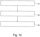
- Fig. 10
- ein Ablaufdiagramm eines Verfahrens zum Klettern eines Kletterwerks gemäß der bevorzugten Ausführungsform der Erfindung.
- Fig. 1 to Fig. 9
- a schematic representation of a self-climbing system for a concrete structure according to a preferred embodiment of the invention; and
- Fig.10
- a flow chart of a method for climbing a climbing structure according to the preferred embodiment of the invention.
In den Figuren der Zeichnungen bezeichnen gleiche Bezugszeichen gleiche oder funktionsgleiche Elemente, Bauteile oder Komponenten, soweit nichts Gegenteiliges angegeben ist.In the figures of the drawings, identical reference symbols designate identical or functionally identical elements, parts or components, unless otherwise stated.
Das Selbstklettersystem 1 weist eine Kletterschiene 10 und ein entlang der Kletterschiene axial verfahrbares Kletterwerk 12 auf. Das Kletterwerk 12 weist einen ersten Kletterkopf 14, einen zweiten Kletterkopf 16 und einen den ersten Kletterkopf 14 mit dem zweiten Kletterkopf 16 verbindenden Linearantrieb 18 auf.The self-climbing
Der erste Kletterkopf 14 und der zweite Kletterkopf 16 weisen jeweils ein zwischen einer Kletterstellung K und einer Raststellung R, insbesondere des Kletterwerks 12, stellbares Stellelement 20, 22 auf. Das Stellelement 20 des ersten Kletterkopfes 14 und das Stellelement 22 des zweiten Kletterkopfes 16 sind durch eine Steuerstange 24 verbunden.The
Die Steuerstange 24 ist dazu ausgebildet, in vorgegebenen Positionen des Linearantriebs 18 eines der Stellelemente 20, 22 mit einem Drehmoment D zu beaufschlagen, um das jeweilige Stellelement 20, 22 zu drehen.The
Die Stellelemente 20, 22 sind in Seitenansicht im Wesentlichen sternförmig ausgebildet, wobei das Stellelement 20 des ersten Kletterkopfes 14 und das Stellelement 22 des zweiten Kletterkopfes 16 jeweils an ihrer Drehachse DA am jeweiligen Kletterkopf 14, 16 angeordnet bzw. mit diesem verbunden sind. Die Steuerstange 24 ist am jeweiligen Stellelement 20, 22 exzentrisch zur Drehachse angeordnet.The adjusting
Die in der vorliegenden Ausführungsform im Wesentlichen sternförmig ausgebildeten Stellelemente 20, 22 sind mit der Steuerstange 24 an einen Endabschnitt eines sich verjüngenden Vorsprungs bzw. Arms des jeweiligen Stellelements angeordnet.The
Alternativ können die Stellelemente 20, 22 eine andere geeignete Form aufweisen. Beispielhafte geeignete Formgebungen sind kreisförmig, hohlkreisförmig, dreieckig oder quaderförmig.Alternatively, the adjusting
Die Steuerstange 24 ist zweiteilig ausgebildet und weist ein Außenrohr 28 und ein aus dem Außenrohr 28 ein- und ausfahrbares Innenrohr 30 auf. Das Innenrohr 30 ist in dem Außenrohr 28 frei bewegbar innerhalb eines vorgegebenen Hubs. Alternativ kann anstelle des Innenrohrs 30 beispielsweise eine Welle vorgesehen sein.The
Das Außenrohr 28 und das Innenrohr 30 oder alternativ die Welle der Steuerstange 24 weisen an einem Hubende ferner ein Federelement 32, insbesondere eine Spiralfeder, auf. Das Federelement 32 leitet die Betätigung des Stellelements 20, 22 des ersten Kletterkopfes 14 und/oder des zweiten Kletterkopfes 16 ein.The
Darüber hinaus weist das Innenrohr 30, insbesondere am Hubende, zumindest abschnittsweise ein Außengewinde 34 auf, an dessen Ende eine Mutter 36 angeordnet ist.In addition, the
Die Mutter 36 bildet einen Anschlag, welcher an einem Gegenanschlag 38, insbesondere einer Durchmesserreduzierung des Außenrohrs 28, anschlägt.The
In der vorliegenden Darstellung stützen sich sowohl das Stellelement 20 des ersten Kletterkopfes 14 als auch das Stellelement 22 des zweiten Kletterkopfes 16 jeweils auf einem Rastklotz 26 ab.In the present illustration, both the adjusting
Das Stellelement 20 des ersten Kletterkopfes 14 und das Stellelement 22 des zweiten Kletterkopfes 16 ist jeweils im Wesentlichen sternförmig ausgebildet, wobei das Stellelement 20, 22 eine radial ausgerichtete erste Flanke 20a, 22a, eine radial ausgerichtete zweite Flanke 20b, 22b und eine radial ausgerichtete dritte Flanke 20c, 22c aufweist.The adjusting
Die Steuerstange 24 ist mit der ersten Flanke 20a, 22a des Stellelements 20 des ersten Kletterkopfes 14 und des Stellelements 22 des zweiten Kletterkopfes 16 verbunden. Die zweite Flanke 20b, 22b der Stellelemente 20, 22 ist dazu ausgebildet, in der Raststellung R des Kletterwerks 12 auf dem Rastklotz 26 aufzuliegen.The
In der vorliegenden Darstellung ist der Linearantrieb 18 ein Stück weit weiter als in
Das Stellelement 20 des ersten Kletterkopfes 4 dreht sich dabei um seine Drehachse DA, an welcher das Stellelement 20 an dem ersten Kletterkopf 14 gelagert ist.The
Das Stellelement 20 des ersten Kletterkopfes 14 ist somit nunmehr nicht mehr in der Ebene E des Rastklotzes 26, sondern außerhalb der Ebene E des Rastklotzes 26 angeordnet.The
Ein Hub H1 des Linearantriebs 18 ist dabei im Wesentlichen identisch zu einem Hub H2 der Steuerstange 24.A stroke H1 of the
Alternativ kann der Hub H1 des Linearantriebs 18 beispielsweise eine Abweichung von bis zu 15% zu einem Hub H2 der Steuerstange 24 aufweisen.Alternatively, the stroke H1 of the
Das Kletterwerk 12 ist bei Erreichen der ersten axialen Endposition 24a der Steuerstange 24 dazu ausgebildet, das in Kletterstellung angeordnete Stellelement 20 des ersten Kletterkopfes von der Kletterstellung in die Raststellung R zu bewegen.When the first
Aufgrund der axial versetzen Anordnung der Steuerstange 24 im Vergleich zu dem Linearantrieb 18 wird das Stellelement 22 des zweiten Kletterkopfes 16 somit von der Kletterstellung in die Raststellung R bewegt.Due to the axially offset arrangement of the
Des Weiteren liegt die am Innenrohr 30 angeordnete Mutter 36, welche einen Anschlag bildet, an dem Gegenanschlag 38 des Außenrohrs 28 auf.Furthermore, the
Der in
Im Falle des Kletterns der Konsole besteht der Unterschied, dass das Stellelement nun nicht mehr auf dem Rastklotz 26 aufliegt, sondern unter diesem liegt. Wenn man die Darstellungen spiegelt lässt sich das Klettern der Schiene darstellen.In the case of the console climbing, the difference is that the adjusting element no longer rests on the locking
Das Verfahren zum Klettern des Kletterwerks 12 an einer an einem Betonbaukörper 2 angeordneten Kletterschiene umfasst ein Bereitstellen S1 eines ersten Kletterkopfes 14, eines zweiten Kletterkopfes 16 und eines den ersten Kletterkopf 14 mit dem zweiten Kletterkopf 16 verbindenden Linearantriebs 18.The method for climbing the climbing
Das Verfahren umfasst ferner ein Bereitstellen S2 des ersten Kletterkopfes 14 und des zweiten Kletterkopfes 16 mit jeweils einem zwischen einer Kletterstellung K und einer Raststellung R, insbesondere des Kletterwerks 12, stellbaren Stellelement 20, 22, wobei das Stellelement 20 des ersten Kletterkopfes 14 und das Stellelement 22 des zweiten Kletterkopfes 16 durch eine Steuerstange 24 verbunden sind.The method further comprises providing S2 the
Darüber hinaus umfasst das Verfahren ein Beaufschlagen S3 zumindest eines der Stellelemente 20, 22 mit einem Drehmoment D in vorgegebenen Positionen 18a, 18b des Linearantriebs 18 durch die Steuerstange 24.In addition, the method comprises applying S3 to at least one of the
Obwohl hierin spezifische Ausführungsformen illustriert und beschrieben wurden, ist es dem Fachmann verständlich, dass eine Vielzahl von alternativen und/oder äquivalenten Implementierungen existieren. Es sollte beachtet werden, dass die beispielhafte Ausführungsform oder beispielhaften Ausführungsformen nur Beispiele sind und nicht dazu dienen, den Umfang, die Anwendbarkeit oder die Konfiguration in irgendeiner Weise einzuschränken.Although specific embodiments have been illustrated and described herein, it will be understood by those skilled in the art that a variety of alternative and/or equivalent implementations exist. It should be noted that the exemplary embodiment or exemplary embodiments are only examples and are not intended to limit the scope, applicability, or configuration in any way.
Vielmehr liefert die vorstehend genannte Zusammenfassung und ausführliche Beschreibung dem Fachmann eine bequeme Anleitung zur Implementierung zumindest einer beispielhaften Ausführungsform, wobei verständlich ist, dass verschiedene Änderungen im Funktionsumfang und der Anordnung der Elemente vorgenommen werden können, ohne vom Umfang der beigefügten Ansprüche und ihrer rechtlichen Äquivalente abzuweichen.Rather, the foregoing summary and detailed description will provide one skilled in the art with a convenient road map for implementing at least one exemplary embodiment, it being understood that various changes in the scope of functionality and arrangement of elements may be made without departing from the scope of the appended claims and their legal equivalents.
Im Allgemeinen beabsichtigt diese Anmeldung, Änderungen bzw. Anpassungen oder Variationen der hierin dargelegten Ausführungsformen abzudecken, sofern diese in den Schutzumfang der Erfindung fallen, welcher nur durch die beigefügten Ansprüche definiert wird.In general, this application is intended to cover modifications, adaptations, or variations of the embodiments set forth herein provided they come within the scope of the invention, which is defined only by the appended claims.
- 11
- SelbstklettersystemSelf-climbing system
- 22
- BetonbaukörperConcrete structure
- 1010
- KletterschieneClimbing rail
- 1212
- KletterwerkClimbing frame
- 1414
- erster Kletterkopffirst climbing head
- 1616
- zweiter Kletterkopfsecond climbing head
- 1818
- Linearantrieblinear actuator
- 18a18a
- erste axiale Endpositionfirst axial end position
- 18b18b
- zweite axiale Endpositionsecond axial end position
- 20,2220,22
- StellelementeControl elements
- 20a, 22a20a, 22a
- erste Flankefirst flank
- 20b, 22b20b, 22b
- zweite Flankesecond flank
- 20c, 22c20c, 22c
- dritte Flankethird flank
- 2424
- SteuerstangeControl rod
- 24a24a
- erste axiale Endpositionfirst axial end position
- 24b24b
- zweite axiale Endpositionsecond axial end position
- 2626
- RastklotzRest block
- 2828
- AußenrohrOuter tube
- 3030
- InnenrohrInner tube
- 3232
- FederelementSpring element
- 3434
- AußengewindeExternal thread
- 3636
- MutterMother
- 3838
- GegenanschlagCounter stop
- 4040
- GriffHandle
- DD
- DrehmomentTorque
- DATHERE
- DrehachseRotation axis
- EE
- Ebenelevel
- H1, H2H1, H2
- HubHub
- KK
- KletterstellungClimbing position
- RR
- RaststellungLocking position
- S1 bis S3S1 to S3
- VerfahrensschritteProcess steps
Claims (17)
- Self-climbing system (1) for a concrete structural body (2), having a climbing rail (10) and having a climbing unit (12) which is axially movable along the climbing rail (10) and which has a first climbing head (14), a second climbing head (16), and a linear drive (18) connecting the first climbing head (14) to the second climbing head (16), wherein the first climbing head (14) and the second climbing head (16) each have an actuating element (20, 22) which is adjustable between a climbing position (K) and a latching position (R), in particular of the climbing unit (12), characterized in that the actuating element (20) of the first climbing head (14) and the actuating element (22) of the second climbing head (16) are connected by a control rod (24), and that the control rod (24) is designed, in predetermined positions (18a, 18b) of the linear drive (18), to apply a torque (D) to at least one of the actuating elements (20, 22).
- Self-climbing system according to claim 1, characterized in that the actuating element (20) of the first climbing head (14) and the actuating element (22) of the second climbing head (16), when passing over a latching block (26) of a plurality of latching blocks (26) arranged on the climbing rail (10) caused by axial movement of the linear drive (18), is movable from the latching position (R) in which the actuating element (20, 22) is arranged at least in portions in the plane (E) of the latching block (26) to the climbing position (K) in which the actuating element (20, 22) is arranged outside the plane (E) of the latching block (26).
- Self-climbing system according to claim 1 or 2, characterized in that the control rod (24) has an outer tube (28) and an inner tube (30) or shaft which can be retracted and extended from the outer tube (28), wherein the control rod (24), when moving the linear drive (18) to a first axial end position (18a), in particular to a fully retracted or extended position, is designed to generate a switching pulse in order to move the actuating element (20) of the first climbing head (14) or of the second climbing head (16) which is arranged in the climbing position (K) from the climbing position (K) to the latching position (R).
- Self-climbing system according to claim 3, characterized in that a stroke (H1) of the linear drive (18) is substantially identical with or with a deviation of up to 15% to a stroke (H2) of the control rod (24), wherein the climbing unit (12), upon reaching a first axial end position (24a) of the control rod (24), is designed to move the actuating element (20) of the first climbing head (14) or of the second climbing head (16) which is arranged in the climbing position (K) from the climbing position (K) to the latching position (R).
- Self-climbing system according to any of the preceding claims, characterized in that when the linear drive (18) is moved to a second axial end position (18b), in particular to a fully retracted position, the control rod (24) is designed to move the actuating element (20) of the first climbing head (14) or of the second climbing head (16) which is arranged in the climbing position (K) from the climbing position (K) to the latching position (R).
- Self-climbing system according to claim 4, characterized in that, when the second axial end position (24b) of the control rod (24) is reached, the climbing unit (12) is designed to move the actuating element (20) of the first climbing head (14) or of the second climbing head (16) which is arranged in the climbing position (K) from the climbing position (K) to the latching position (R).
- Self-climbing system according to any of the preceding claims, characterized in that the actuating element (20) of the first climbing head (14) and the actuating element (22) of the second climbing head (16) are arranged on its axis of rotation (DA) on the respective climbing head (14, 16), and wherein the control rod (24) is arranged on the respective actuating element (20, 22) eccentrically to the axis of rotation.
- Self-climbing system according to any of the preceding claims, characterized in that the climbing unit (12) is designed in such a manner that, when the climbing unit (12) is operated in the latching position (R), the actuating element (20, 22) of the first climbing head (14) or of the second climbing head (16) is supported on a latching block (26) arranged on the climbing rail (10), and wherein the other actuating element (20, 22) can be actuated by the control rod (24).
- Self-climbing system according to any of claims 3, 4, and 6 or, insofar as referring back to claim 3, according to any of claims 5, 7, and 8, characterized in that the outer tube (28) and the inner tube (30) or the shaft of the control rod (24) have a spring element (32), in particular a spiral spring, at one stroke end, which initiates the actuation of the actuating element (20, 22) of the first climbing head (14) and/or of the second climbing head (16).
- Self-climbing system according to claim 9, characterized in that the inner tube (30), in particular at the stroke end, has at least in portions an external thread (34), at the end of which a nut (36) is arranged, wherein the nut (36) forms a stop which abuts against a counter stop (38), in particular a diameter reduction, of the outer tube (28).
- Self-climbing system according to any of the preceding claims, characterized in that the control rod (24) has a handle (40) which, when actuated, in particular by a user, is designed to move the actuating element (20, 22) of the first climbing head (14) or of the second climbing head (16) between the climbing position (K) and the latching position (R).
- Self-climbing system according to any of the preceding claims, characterized in that the linear drive is formed by an actuating cylinder which has a piston rod axially adjustable in a cylinder, wherein the piston rod is connected at an axial end portion to the first climbing head (14), and wherein the cylinder is connected at an axial end portion to the second climbing head (16).
- Self-climbing system according to any of the preceding claims, characterized in that the actuating element (20) of the first climbing head (14) and the actuating element (22) of the second climbing head (16) are each designed to be substantially star-shaped, wherein the actuating element (20, 22) has a radially aligned first flank (20a, 22a), a radially aligned second flank (20b, 22b), and a radially aligned third flank (20c, 22c).
- Self-climbing system according to claim 13, characterized in that the control rod (24) is connected to the first flank (20a, 22a) of the actuating element (20) of the first climbing head (14) and of the actuating element (22) of the second climbing head (16), and wherein the second flank (20b, 22b) of the actuating elements (20, 22) is designed to rest on the latching block (26) in the latching position (R) of the climbing unit (12).
- Method for climbing of a climbing unit (12) on a climbing rail (10) arranged on a concrete structural body (2), comprising the steps:providing (S1) a first climbing head (14), a second climbing head (16), and a linear drive (18) connecting the first climbing head (14) to the second climbing head (16);providing (S2) the first climbing head (14) and the second climbing head (16) each with an actuating element (20, 22) adjustable between a climbing position (K) and a latching position (R), in particular of the climbing unit (12), wherein the actuating element (20) of the first climbing head (14) and the actuating element (22) of the second climbing head (16) are connected by a control rod (24); andapplying (S3) a torque (D) to at least one of the actuating elements (20, 22) in predetermined positions (18a, 18b) of the linear drive (18) by the control rod (24).
- Method according to claim 15, characterized in that the actuating element (20) of the first climbing head (14) and the actuating element (22) of the second climbing head (16), when passing over a latching block (26) of a plurality of latching blocks (26) arranged on the climbing rail (10) caused by axial movement of the linear drive (18), is moved from the latching position (R) in which the actuating element (20, 22) is arranged at least in portions in the plane (E) of the latching block (26) to the climbing position (K) in which the actuating element (20, 22) is arranged outside the plane (E) of the latching block (26).
- Method according to claim 15 or 16, characterized in that when the linear drive (18) is moved to a first axial end position (18a), in particular to a fully extended position, the control rod (24) generates a switching pulse to move the actuating element (20) of the first climbing head (14) or of the second climbing head (16) which is arranged in the climbing position (K) from the climbing position (K) to the latching position (R).
Applications Claiming Priority (2)
| Application Number | Priority Date | Filing Date | Title |
|---|---|---|---|
| DE102020124646.3A DE102020124646A1 (en) | 2020-09-22 | 2020-09-22 | Self-climbing system for a concrete structure and self-climbing method |
| PCT/EP2021/074401 WO2022063547A1 (en) | 2020-09-22 | 2021-09-03 | Self-climbing system for a concrete structural body, and self-climbing method |
Publications (2)
| Publication Number | Publication Date |
|---|---|
| EP4217552A1 EP4217552A1 (en) | 2023-08-02 |
| EP4217552B1 true EP4217552B1 (en) | 2024-07-17 |
Family
ID=77864548
Family Applications (1)
| Application Number | Title | Priority Date | Filing Date |
|---|---|---|---|
| EP21773507.5A Active EP4217552B1 (en) | 2020-09-22 | 2021-09-03 | Self-climbing system for a concrete structural body, and self-climbing method |
Country Status (5)
| Country | Link |
|---|---|
| US (1) | US20230358060A1 (en) |
| EP (1) | EP4217552B1 (en) |
| KR (1) | KR20230067633A (en) |
| DE (1) | DE102020124646A1 (en) |
| WO (1) | WO2022063547A1 (en) |
Families Citing this family (3)
| Publication number | Priority date | Publication date | Assignee | Title |
|---|---|---|---|---|
| DE102019104548A1 (en) * | 2019-02-22 | 2020-08-27 | Peri Gmbh | LIFT DRIVE FOR A RAIL-GUIDED FREE-FRAME DEVICE |
| DE102023134914A1 (en) * | 2023-12-13 | 2025-06-18 | Schwing Gmbh | Support column |
| CN119933341B (en) * | 2025-04-09 | 2025-06-06 | 上海建工一建集团有限公司 | Self-climbing power system and method for integrally lifting steel platform |
Family Cites Families (5)
| Publication number | Priority date | Publication date | Assignee | Title |
|---|---|---|---|---|
| DE4302197A1 (en) * | 1993-01-27 | 1994-07-28 | Peri Gmbh | Climbing device, in particular for a climbing frame |
| ES2339442T3 (en) | 2003-11-27 | 2010-05-20 | Ulma C Y E, S. Coop. | TREPADOR SYSTEM FOR FORMWORKS, ANDAMIOS AND LOADS IN GENERAL. |
| KR100704720B1 (en) * | 2006-05-19 | 2007-04-23 | 금강공업 주식회사 | Temporary lifting device and temporary lifting method |
| DE102007026020A1 (en) * | 2007-06-04 | 2008-12-11 | Doka Industrie Gmbh | Self-climbing system and method for concreting a beam and / or assembling a finished part by means of a self-climbing system |
| PL2995749T3 (en) | 2014-09-10 | 2022-09-12 | Doka Gmbh | Method and apparatus for lowering a formwork or a protective element |
-
2020
- 2020-09-22 DE DE102020124646.3A patent/DE102020124646A1/en active Pending
-
2021
- 2021-09-03 EP EP21773507.5A patent/EP4217552B1/en active Active
- 2021-09-03 KR KR1020237011101A patent/KR20230067633A/en active Pending
- 2021-09-03 US US18/246,229 patent/US20230358060A1/en active Pending
- 2021-09-03 WO PCT/EP2021/074401 patent/WO2022063547A1/en not_active Ceased
Also Published As
| Publication number | Publication date |
|---|---|
| US20230358060A1 (en) | 2023-11-09 |
| KR20230067633A (en) | 2023-05-16 |
| EP4217552A1 (en) | 2023-08-02 |
| WO2022063547A1 (en) | 2022-03-31 |
| DE102020124646A1 (en) | 2022-03-24 |
Similar Documents
| Publication | Publication Date | Title |
|---|---|---|
| EP3827146B1 (en) | Lift drive for a rail-guided climbing system and method of lifting a rail guided climbing system | |
| EP0681635B1 (en) | Climbing device, in particular for a climbing scaffold | |
| EP3762566B1 (en) | Method for displacing a ceiling formwork, collision protection element, and ceiling formwork, supporting device and incremental launching device comprising such a collision protection element | |
| EP3752692B1 (en) | Climbing system and method for operating a climbing system | |
| EP4217552A1 (en) | Self-climbing system for a concrete structural body, and self-climbing method | |
| WO2020064423A1 (en) | Climbing unit for a formwork scaffolding | |
| EP3354829B1 (en) | Motor vehicle actuating device | |
| WO2014079628A1 (en) | Gripping apparatus for handling reinforcement cages for tower segments of a wind turbine | |
| EP0373617A2 (en) | Shiftable scaffold movable in sections on a wall | |
| EP3146166B1 (en) | Camshaft | |
| DE9408289U1 (en) | Telescopic boom with multi-stage hydraulic cylinder | |
| DE102011077569A1 (en) | drum | |
| DE2140235A1 (en) | System with large, rotating brushes for washing vehicles of different types | |
| DE1579067B1 (en) | Rotatable tire building drum with radially retractable and extendable drum segments | |
| WO1998054041A1 (en) | Device for locking end positions of mobile switch parts | |
| DE102023134914A1 (en) | Support column | |
| EP0332801B1 (en) | Apparatus for changing the cross-sectional shape of can blanks | |
| EP3919683B1 (en) | Connecting device | |
| EP0022121B1 (en) | Supporting and guiding frame for continuous casting plants | |
| DE3607953C2 (en) | ||
| DE2360532A1 (en) | Assembly machine for producing reinforcing cages for concrete tubes - welds wire coils to set of longitudinal bars | |
| DE19947188C2 (en) | Extending table with a table frame | |
| EP0488990A1 (en) | Telescopic jib with single screw actuator | |
| DE2633022B1 (en) | Crane jib telescoping drive - has nuts on screwed spindle locked in turn to respective jib sections | |
| DE102015209872A1 (en) | applicator |
Legal Events
| Date | Code | Title | Description |
|---|---|---|---|
| STAA | Information on the status of an ep patent application or granted ep patent |
Free format text: STATUS: UNKNOWN |
|
| STAA | Information on the status of an ep patent application or granted ep patent |
Free format text: STATUS: THE INTERNATIONAL PUBLICATION HAS BEEN MADE |
|
| PUAI | Public reference made under article 153(3) epc to a published international application that has entered the european phase |
Free format text: ORIGINAL CODE: 0009012 |
|
| STAA | Information on the status of an ep patent application or granted ep patent |
Free format text: STATUS: REQUEST FOR EXAMINATION WAS MADE |
|
| 17P | Request for examination filed |
Effective date: 20230417 |
|
| AK | Designated contracting states |
Kind code of ref document: A1 Designated state(s): AL AT BE BG CH CY CZ DE DK EE ES FI FR GB GR HR HU IE IS IT LI LT LU LV MC MK MT NL NO PL PT RO RS SE SI SK SM TR |
|
| DAV | Request for validation of the european patent (deleted) | ||
| DAX | Request for extension of the european patent (deleted) | ||
| GRAP | Despatch of communication of intention to grant a patent |
Free format text: ORIGINAL CODE: EPIDOSNIGR1 |
|
| STAA | Information on the status of an ep patent application or granted ep patent |
Free format text: STATUS: GRANT OF PATENT IS INTENDED |
|
| INTG | Intention to grant announced |
Effective date: 20240314 |
|
| GRAS | Grant fee paid |
Free format text: ORIGINAL CODE: EPIDOSNIGR3 |
|
| GRAA | (expected) grant |
Free format text: ORIGINAL CODE: 0009210 |
|
| STAA | Information on the status of an ep patent application or granted ep patent |
Free format text: STATUS: THE PATENT HAS BEEN GRANTED |
|
| AK | Designated contracting states |
Kind code of ref document: B1 Designated state(s): AL AT BE BG CH CY CZ DE DK EE ES FI FR GB GR HR HU IE IS IT LI LT LU LV MC MK MT NL NO PL PT RO RS SE SI SK SM TR |
|
| REG | Reference to a national code |
Ref country code: CH Ref legal event code: EP |
|
| REG | Reference to a national code |
Ref country code: DE Ref legal event code: R096 Ref document number: 502021004428 Country of ref document: DE |
|
| REG | Reference to a national code |
Ref country code: IE Ref legal event code: FG4D Free format text: LANGUAGE OF EP DOCUMENT: GERMAN |
|
| REG | Reference to a national code |
Ref country code: LT Ref legal event code: MG9D |
|
| REG | Reference to a national code |
Ref country code: NL Ref legal event code: MP Effective date: 20240717 |
|
| PG25 | Lapsed in a contracting state [announced via postgrant information from national office to epo] |
Ref country code: PT Free format text: LAPSE BECAUSE OF FAILURE TO SUBMIT A TRANSLATION OF THE DESCRIPTION OR TO PAY THE FEE WITHIN THE PRESCRIBED TIME-LIMIT Effective date: 20241118 |
|
| PG25 | Lapsed in a contracting state [announced via postgrant information from national office to epo] |
Ref country code: NL Free format text: LAPSE BECAUSE OF FAILURE TO SUBMIT A TRANSLATION OF THE DESCRIPTION OR TO PAY THE FEE WITHIN THE PRESCRIBED TIME-LIMIT Effective date: 20240717 |
|
| PG25 | Lapsed in a contracting state [announced via postgrant information from national office to epo] |
Ref country code: PT Free format text: LAPSE BECAUSE OF FAILURE TO SUBMIT A TRANSLATION OF THE DESCRIPTION OR TO PAY THE FEE WITHIN THE PRESCRIBED TIME-LIMIT Effective date: 20241118 Ref country code: NL Free format text: LAPSE BECAUSE OF FAILURE TO SUBMIT A TRANSLATION OF THE DESCRIPTION OR TO PAY THE FEE WITHIN THE PRESCRIBED TIME-LIMIT Effective date: 20240717 |
|
| PG25 | Lapsed in a contracting state [announced via postgrant information from national office to epo] |
Ref country code: NO Free format text: LAPSE BECAUSE OF FAILURE TO SUBMIT A TRANSLATION OF THE DESCRIPTION OR TO PAY THE FEE WITHIN THE PRESCRIBED TIME-LIMIT Effective date: 20241017 |
|
| PG25 | Lapsed in a contracting state [announced via postgrant information from national office to epo] |
Ref country code: FI Free format text: LAPSE BECAUSE OF FAILURE TO SUBMIT A TRANSLATION OF THE DESCRIPTION OR TO PAY THE FEE WITHIN THE PRESCRIBED TIME-LIMIT Effective date: 20240717 Ref country code: GR Free format text: LAPSE BECAUSE OF FAILURE TO SUBMIT A TRANSLATION OF THE DESCRIPTION OR TO PAY THE FEE WITHIN THE PRESCRIBED TIME-LIMIT Effective date: 20241018 Ref country code: PL Free format text: LAPSE BECAUSE OF FAILURE TO SUBMIT A TRANSLATION OF THE DESCRIPTION OR TO PAY THE FEE WITHIN THE PRESCRIBED TIME-LIMIT Effective date: 20240717 |
|
| PG25 | Lapsed in a contracting state [announced via postgrant information from national office to epo] |
Ref country code: BG Free format text: LAPSE BECAUSE OF FAILURE TO SUBMIT A TRANSLATION OF THE DESCRIPTION OR TO PAY THE FEE WITHIN THE PRESCRIBED TIME-LIMIT Effective date: 20240717 |
|
| PG25 | Lapsed in a contracting state [announced via postgrant information from national office to epo] |
Ref country code: LV Free format text: LAPSE BECAUSE OF FAILURE TO SUBMIT A TRANSLATION OF THE DESCRIPTION OR TO PAY THE FEE WITHIN THE PRESCRIBED TIME-LIMIT Effective date: 20240717 |
|
| PG25 | Lapsed in a contracting state [announced via postgrant information from national office to epo] |
Ref country code: IS Free format text: LAPSE BECAUSE OF FAILURE TO SUBMIT A TRANSLATION OF THE DESCRIPTION OR TO PAY THE FEE WITHIN THE PRESCRIBED TIME-LIMIT Effective date: 20241117 |
|
| PG25 | Lapsed in a contracting state [announced via postgrant information from national office to epo] |
Ref country code: HR Free format text: LAPSE BECAUSE OF FAILURE TO SUBMIT A TRANSLATION OF THE DESCRIPTION OR TO PAY THE FEE WITHIN THE PRESCRIBED TIME-LIMIT Effective date: 20240717 |
|
| PG25 | Lapsed in a contracting state [announced via postgrant information from national office to epo] |
Ref country code: ES Free format text: LAPSE BECAUSE OF FAILURE TO SUBMIT A TRANSLATION OF THE DESCRIPTION OR TO PAY THE FEE WITHIN THE PRESCRIBED TIME-LIMIT Effective date: 20240717 Ref country code: RS Free format text: LAPSE BECAUSE OF FAILURE TO SUBMIT A TRANSLATION OF THE DESCRIPTION OR TO PAY THE FEE WITHIN THE PRESCRIBED TIME-LIMIT Effective date: 20241017 |
|
| PG25 | Lapsed in a contracting state [announced via postgrant information from national office to epo] |
Ref country code: RS Free format text: LAPSE BECAUSE OF FAILURE TO SUBMIT A TRANSLATION OF THE DESCRIPTION OR TO PAY THE FEE WITHIN THE PRESCRIBED TIME-LIMIT Effective date: 20241017 Ref country code: PL Free format text: LAPSE BECAUSE OF FAILURE TO SUBMIT A TRANSLATION OF THE DESCRIPTION OR TO PAY THE FEE WITHIN THE PRESCRIBED TIME-LIMIT Effective date: 20240717 Ref country code: NO Free format text: LAPSE BECAUSE OF FAILURE TO SUBMIT A TRANSLATION OF THE DESCRIPTION OR TO PAY THE FEE WITHIN THE PRESCRIBED TIME-LIMIT Effective date: 20241017 Ref country code: LV Free format text: LAPSE BECAUSE OF FAILURE TO SUBMIT A TRANSLATION OF THE DESCRIPTION OR TO PAY THE FEE WITHIN THE PRESCRIBED TIME-LIMIT Effective date: 20240717 Ref country code: IS Free format text: LAPSE BECAUSE OF FAILURE TO SUBMIT A TRANSLATION OF THE DESCRIPTION OR TO PAY THE FEE WITHIN THE PRESCRIBED TIME-LIMIT Effective date: 20241117 Ref country code: HR Free format text: LAPSE BECAUSE OF FAILURE TO SUBMIT A TRANSLATION OF THE DESCRIPTION OR TO PAY THE FEE WITHIN THE PRESCRIBED TIME-LIMIT Effective date: 20240717 Ref country code: GR Free format text: LAPSE BECAUSE OF FAILURE TO SUBMIT A TRANSLATION OF THE DESCRIPTION OR TO PAY THE FEE WITHIN THE PRESCRIBED TIME-LIMIT Effective date: 20241018 Ref country code: FI Free format text: LAPSE BECAUSE OF FAILURE TO SUBMIT A TRANSLATION OF THE DESCRIPTION OR TO PAY THE FEE WITHIN THE PRESCRIBED TIME-LIMIT Effective date: 20240717 Ref country code: ES Free format text: LAPSE BECAUSE OF FAILURE TO SUBMIT A TRANSLATION OF THE DESCRIPTION OR TO PAY THE FEE WITHIN THE PRESCRIBED TIME-LIMIT Effective date: 20240717 Ref country code: BG Free format text: LAPSE BECAUSE OF FAILURE TO SUBMIT A TRANSLATION OF THE DESCRIPTION OR TO PAY THE FEE WITHIN THE PRESCRIBED TIME-LIMIT Effective date: 20240717 |
|
| PG25 | Lapsed in a contracting state [announced via postgrant information from national office to epo] |
Ref country code: RO Free format text: LAPSE BECAUSE OF FAILURE TO SUBMIT A TRANSLATION OF THE DESCRIPTION OR TO PAY THE FEE WITHIN THE PRESCRIBED TIME-LIMIT Effective date: 20240717 Ref country code: SM Free format text: LAPSE BECAUSE OF FAILURE TO SUBMIT A TRANSLATION OF THE DESCRIPTION OR TO PAY THE FEE WITHIN THE PRESCRIBED TIME-LIMIT Effective date: 20240717 Ref country code: DK Free format text: LAPSE BECAUSE OF FAILURE TO SUBMIT A TRANSLATION OF THE DESCRIPTION OR TO PAY THE FEE WITHIN THE PRESCRIBED TIME-LIMIT Effective date: 20240717 |
|
| REG | Reference to a national code |
Ref country code: DE Ref legal event code: R097 Ref document number: 502021004428 Country of ref document: DE |
|
| PG25 | Lapsed in a contracting state [announced via postgrant information from national office to epo] |
Ref country code: MC Free format text: LAPSE BECAUSE OF FAILURE TO SUBMIT A TRANSLATION OF THE DESCRIPTION OR TO PAY THE FEE WITHIN THE PRESCRIBED TIME-LIMIT Effective date: 20240717 Ref country code: EE Free format text: LAPSE BECAUSE OF FAILURE TO SUBMIT A TRANSLATION OF THE DESCRIPTION OR TO PAY THE FEE WITHIN THE PRESCRIBED TIME-LIMIT Effective date: 20240717 |
|
| PG25 | Lapsed in a contracting state [announced via postgrant information from national office to epo] |
Ref country code: CZ Free format text: LAPSE BECAUSE OF FAILURE TO SUBMIT A TRANSLATION OF THE DESCRIPTION OR TO PAY THE FEE WITHIN THE PRESCRIBED TIME-LIMIT Effective date: 20240717 |
|
| PG25 | Lapsed in a contracting state [announced via postgrant information from national office to epo] |
Ref country code: SK Free format text: LAPSE BECAUSE OF FAILURE TO SUBMIT A TRANSLATION OF THE DESCRIPTION OR TO PAY THE FEE WITHIN THE PRESCRIBED TIME-LIMIT Effective date: 20240717 |
|
| REG | Reference to a national code |
Ref country code: CH Ref legal event code: PL |
|
| PG25 | Lapsed in a contracting state [announced via postgrant information from national office to epo] |
Ref country code: LU Free format text: LAPSE BECAUSE OF NON-PAYMENT OF DUE FEES Effective date: 20240903 |
|
| PLBE | No opposition filed within time limit |
Free format text: ORIGINAL CODE: 0009261 |
|
| STAA | Information on the status of an ep patent application or granted ep patent |
Free format text: STATUS: NO OPPOSITION FILED WITHIN TIME LIMIT |
|
| 26N | No opposition filed |
Effective date: 20250422 |
|
| REG | Reference to a national code |
Ref country code: BE Ref legal event code: MM Effective date: 20240930 |
|
| PG25 | Lapsed in a contracting state [announced via postgrant information from national office to epo] |
Ref country code: BE Free format text: LAPSE BECAUSE OF NON-PAYMENT OF DUE FEES Effective date: 20240930 |
|
| PG25 | Lapsed in a contracting state [announced via postgrant information from national office to epo] |
Ref country code: FR Free format text: LAPSE BECAUSE OF NON-PAYMENT OF DUE FEES Effective date: 20240917 |
|
| PG25 | Lapsed in a contracting state [announced via postgrant information from national office to epo] |
Ref country code: CH Free format text: LAPSE BECAUSE OF NON-PAYMENT OF DUE FEES Effective date: 20240930 |
|
| PG25 | Lapsed in a contracting state [announced via postgrant information from national office to epo] |
Ref country code: IE Free format text: LAPSE BECAUSE OF NON-PAYMENT OF DUE FEES Effective date: 20240903 |
|
| PG25 | Lapsed in a contracting state [announced via postgrant information from national office to epo] |
Ref country code: SE Free format text: LAPSE BECAUSE OF FAILURE TO SUBMIT A TRANSLATION OF THE DESCRIPTION OR TO PAY THE FEE WITHIN THE PRESCRIBED TIME-LIMIT Effective date: 20240717 |
|
| PGFP | Annual fee paid to national office [announced via postgrant information from national office to epo] |
Ref country code: DE Payment date: 20250917 Year of fee payment: 5 |
|
| PGFP | Annual fee paid to national office [announced via postgrant information from national office to epo] |
Ref country code: AT Payment date: 20251020 Year of fee payment: 5 |
|
| PG25 | Lapsed in a contracting state [announced via postgrant information from national office to epo] |
Ref country code: IT Free format text: LAPSE BECAUSE OF NON-PAYMENT OF DUE FEES Effective date: 20240903 |
|
| PG25 | Lapsed in a contracting state [announced via postgrant information from national office to epo] |
Ref country code: CY Free format text: LAPSE BECAUSE OF FAILURE TO SUBMIT A TRANSLATION OF THE DESCRIPTION OR TO PAY THE FEE WITHIN THE PRESCRIBED TIME-LIMIT; INVALID AB INITIO Effective date: 20210903 |
|
| PG25 | Lapsed in a contracting state [announced via postgrant information from national office to epo] |
Ref country code: HU Free format text: LAPSE BECAUSE OF FAILURE TO SUBMIT A TRANSLATION OF THE DESCRIPTION OR TO PAY THE FEE WITHIN THE PRESCRIBED TIME-LIMIT; INVALID AB INITIO Effective date: 20210903 |
|
| PG25 | Lapsed in a contracting state [announced via postgrant information from national office to epo] |
Ref country code: IT Free format text: LAPSE BECAUSE OF NON-PAYMENT OF DUE FEES Effective date: 20240903 |
|
| PGFP | Annual fee paid to national office [announced via postgrant information from national office to epo] |
Ref country code: IT Payment date: 20240930 Year of fee payment: 4 |
|
| PGRI | Patent reinstated in contracting state [announced from national office to epo] |
Ref country code: IT Effective date: 20240930 |