EP4215686B1 - Flüssigkeitsflussumleiter - Google Patents
Flüssigkeitsflussumleiter Download PDFInfo
- Publication number
- EP4215686B1 EP4215686B1 EP22153017.3A EP22153017A EP4215686B1 EP 4215686 B1 EP4215686 B1 EP 4215686B1 EP 22153017 A EP22153017 A EP 22153017A EP 4215686 B1 EP4215686 B1 EP 4215686B1
- Authority
- EP
- European Patent Office
- Prior art keywords
- liquid outlet
- liquid
- downpipe
- flow diverter
- liquid flow
- Prior art date
- Legal status (The legal status is an assumption and is not a legal conclusion. Google has not performed a legal analysis and makes no representation as to the accuracy of the status listed.)
- Active
Links
Images



Classifications
-
- F—MECHANICAL ENGINEERING; LIGHTING; HEATING; WEAPONS; BLASTING
- F16—ENGINEERING ELEMENTS AND UNITS; GENERAL MEASURES FOR PRODUCING AND MAINTAINING EFFECTIVE FUNCTIONING OF MACHINES OR INSTALLATIONS; THERMAL INSULATION IN GENERAL
- F16L—PIPES; JOINTS OR FITTINGS FOR PIPES; SUPPORTS FOR PIPES, CABLES OR PROTECTIVE TUBING; MEANS FOR THERMAL INSULATION IN GENERAL
- F16L41/00—Branching pipes; Joining pipes to walls
- F16L41/08—Joining pipes to walls or pipes, the joined pipe axis being perpendicular to the plane of a wall or to the axis of another pipe
- F16L41/12—Joining pipes to walls or pipes, the joined pipe axis being perpendicular to the plane of a wall or to the axis of another pipe using attaching means embracing the pipe
-
- B—PERFORMING OPERATIONS; TRANSPORTING
- B65—CONVEYING; PACKING; STORING; HANDLING THIN OR FILAMENTARY MATERIAL
- B65D—CONTAINERS FOR STORAGE OR TRANSPORT OF ARTICLES OR MATERIALS, e.g. BAGS, BARRELS, BOTTLES, BOXES, CANS, CARTONS, CRATES, DRUMS, JARS, TANKS, HOPPERS, FORWARDING CONTAINERS; ACCESSORIES, CLOSURES, OR FITTINGS THEREFOR; PACKAGING ELEMENTS; PACKAGES
- B65D88/00—Large containers
- B65D88/02—Large containers rigid
-
- E—FIXED CONSTRUCTIONS
- E04—BUILDING
- E04D—ROOF COVERINGS; SKY-LIGHTS; GUTTERS; ROOF-WORKING TOOLS
- E04D13/00—Special arrangements or devices in connection with roof coverings; Protection against birds; Roof drainage ; Sky-lights
- E04D13/04—Roof drainage; Drainage fittings in flat roofs, balconies or the like
-
- E—FIXED CONSTRUCTIONS
- E04—BUILDING
- E04D—ROOF COVERINGS; SKY-LIGHTS; GUTTERS; ROOF-WORKING TOOLS
- E04D13/00—Special arrangements or devices in connection with roof coverings; Protection against birds; Roof drainage ; Sky-lights
- E04D13/04—Roof drainage; Drainage fittings in flat roofs, balconies or the like
- E04D13/08—Down pipes; Special clamping means therefor
-
- F—MECHANICAL ENGINEERING; LIGHTING; HEATING; WEAPONS; BLASTING
- F16—ENGINEERING ELEMENTS AND UNITS; GENERAL MEASURES FOR PRODUCING AND MAINTAINING EFFECTIVE FUNCTIONING OF MACHINES OR INSTALLATIONS; THERMAL INSULATION IN GENERAL
- F16L—PIPES; JOINTS OR FITTINGS FOR PIPES; SUPPORTS FOR PIPES, CABLES OR PROTECTIVE TUBING; MEANS FOR THERMAL INSULATION IN GENERAL
- F16L41/00—Branching pipes; Joining pipes to walls
- F16L41/04—Tapping pipe walls, i.e. making connections through the walls of pipes while they are carrying fluids; Fittings therefor
-
- E—FIXED CONSTRUCTIONS
- E04—BUILDING
- E04D—ROOF COVERINGS; SKY-LIGHTS; GUTTERS; ROOF-WORKING TOOLS
- E04D13/00—Special arrangements or devices in connection with roof coverings; Protection against birds; Roof drainage ; Sky-lights
- E04D13/04—Roof drainage; Drainage fittings in flat roofs, balconies or the like
- E04D13/08—Down pipes; Special clamping means therefor
- E04D2013/082—Down pipe branches
Definitions
- the present disclosure relates to a liquid flow diverter which may allow collection of a liquid from a drainage pipe or a downpipe. More specifically, the present disclosure relates to an easy, convenient, and safe retrofitting of the liquid flow diverter with the drainage pipe or the downpipe.
- a liquid flow diverter may be used to collect a liquid (say rainwater) from a drainage pipe or a downpipe.
- the drainage pipe or the downpipe have generally applications with a building, gardens, and other similar installations.
- the liquid flow diverter may collect and communicate the liquid from the downpipe with a liquid reservoir (say a liquid storage tank).
- a liquid flow diverter may include a collection unit and a liquid outlet.
- the collection unit of the liquid flow diverter may be readily and removably inserted in any downpipe via a drill hole drilled through a wall of the downpipe.
- the '979 reference provides a water collection device for collecting water, in particular rainwater, in a downpipe.
- the water collection device includes a collection unit.
- the collection unit includes a collection groove made of an elastically deformable material that resets and which may be inserted into the downspout via a lateral insertion opening.
- the collection unit further includes a drainage socket with a drainage channel. The drainage socket may be connected to the collection groove and may be fixable on the downspout in the region of the insertion opening and via which collected water may drain out of the downspout.
- the apparatus or the method may be such that the direct contact of the user with the sharp drill hole while inserting the collection unit of the liquid flow diverter in the downpipe may be substantially or completely prevented.
- a further example of a device for catching and branching-off rainwater from a downpipe is disclosed in the US patent application US 2011/0315610 A1 (hereinafter referred to as ⁇ 610 reference).
- the device includes a tensioning system for mounting and fixing a plug-in branch pipe at the downpipe.
- the tensioning system comprises a spigot nut, from which the plug-in branch pipe projects.
- a filter and/or metering device is optionally arranged from which a discharge piece projects.
- the optionally filter and/or metering device comprises a filter and/or metering pot incorporated into the plug-in branch pipe and a removable and/or at least rotational lid.
- the plug-in branch pipe with a sickle-shaped catching blade ahead projects into the downpipe.
- the plug-in branch pipe is fluid coupled to the downpipe via the spigot nut and a sleeve comprising engagement hooks.
- the '610 reference discloses the sickle-shaped catching blade which is fluidically and unmovably connected to the plug-in branch pipe which is in turn unmovably connected with the discharge piece via the optionally filter and/or metering device.
- the plug-in branch pipe is unmovably connected respectively fluid coupled to the downpipe via the tensioning system. Therefore, the '610 reference discloses that the catching blade is fluid coupled to the downpipe by the plug-in branch pipe which in turn is non-movable relative to the catching blade.
- the '610 reference does not disclose that the liquid outlet allows fluid coupling of the liquid flow diverter with the downpipe, wherein the liquid outlet is slidably coupled with the first end of the body, such that the liquid outlet is slidable relative to the first end of the body between a first position and a second position. Therefore, there is still a need for a apparatus or a method for easy, convenient, efficient and safe retrofitting of the liquid flow diverter with the downpipe.
- the apparatus or the method may be such that the direct contact of the user with the sharp drillhole while inserting the collection unit of the liquid flow diverter in the downpipe may be substantially or completely prevented.
- WO 2023/072459 A1 discloses a fluid flow diverter according to Art. 54(3) EPC.
- the liquid flow diverter for the downpipe includes a body.
- the body includes a channel profile between a first end and a second end.
- the channel profile allows flow of a liquid therein.
- a liquid outlet is adapted to be coupled with the first end of the body.
- the liquid outlet allows fluid coupling of the liquid flow diverter with the downpipe.
- the liquid flow diverter is characterized in that the liquid outlet is slidably coupled with the first end of the body, such that the liquid outlet is slidable relative to the first end of the body between a first position and a second position.
- the liquid outlet is adapted to be fluidly de-coupled with the first end of the body in the first position. Further, the liquid outlet is adapted to be fluidly coupled with the first end of the body in the second position.
- the present disclosure provides a liquid flow diverter that is fluidly coupled with a downpipe via a liquid outlet.
- the liquid outlet may further be fluidly coupled with a tap, or a liquid reservoir located even at a remote location, via a hose and the like for various domestic as well as industrial applications.
- the liquid outlet is slidable with respect to the body of the liquid flow diverter and may be used as a handle to make retrofitting of the liquid flow diverter with the downpipe as an easy, convenient, efficient, and safe process.
- an outflow of the liquid from the downpipe is automatically stopped.
- the liquid collected in the liquid flow diverter may not be accessed if the liquid outlet is not fluidly coupled with the body of the liquid flow diverter.
- the outflow of the liquid from the downpipe is automatically stopped.
- problems such as leakage and others may be prevented leading to judicious use of the liquid.
- the liquid outlet includes a spout and a plurality of ribs, wherein the plurality of ribs allows to slidably couple the liquid outlet with the first end of the body.
- the sliding feature of the liquid outlet relative to the first end of the body may allow the liquid outlet to be used as the handle.
- the liquid outlet may be used to properly retrofit the liquid flow diverter with the downpipe.
- the liquid outlet may be used to properly position or arrange the body of the liquid flow diverter within a hollow space inside the downpipe such that the body collects maximum possible amount of the liquid for flow in the channel profile.
- the plurality of ribs engages with a plurality of protrusions on the first end of the body.
- the plurality of ribs of the liquid outlet together with the plurality of protrusions on the first end of the body form an irremovable coupling between the body and the liquid outlet.
- the coupling allows the liquid outlet to slide to the first position and the second position relative to the body.
- the coupling may not be removed completely to separate out the liquid outlet and the body from each other.
- the channel profile has a helix shape.
- the helix shape of the channel profile may allow the liquid therein to flow under the influence of gravity towards the liquid outlet of the liquid flow diverter. Thus, all the liquid collected in the channel profile may easily flow towards the liquid outlet and not stall within the channel profile.
- a method for retrofitting the liquid flow diverter with the downpipe includes drilling a hole in the downpipe.
- the method further includes holding the liquid outlet of the liquid flow diverter such that the liquid outlet is adapted to be coupled with the body of the liquid flow diverter, wherein the body defines the channel profile between the first end and the second end.
- the method includes inserting the body inside the downpipe via the hole and manipulating an arrangement of the body inside the downpipe with the liquid outlet such that the body captures liquid inside the downpipe.
- the method is characterized in that the liquid outlet is slidably coupled with the first end of the body, such that the liquid outlet is slidable relative to the first end of the body between the first position and the second position.
- the liquid outlet is adapted to be fluidly de-coupled with the first end of the body in the first position. Further, the liquid outlet is adapted to be fluidly coupled with the first end of the body in the second position such that the liquid outlet, when in the second position, completes the retrofitting of the liquid flow diverter with the downpipe.
- the method is easy, convenient and safe to execute. A user may use the liquid outlet as the handle to properly insert the body of the liquid flow diverter inside the downpipe. Thus, the user may not get in direct contact with the sharp drill hole thereby preventing any potential injuries.
- the retrofitting arrangement of the liquid flow diverter with the downpipe is additionally secured by a belt.
- the belt may adapt to the shape of the downpipe and consequently wrap around the downpipe to further strengthen the retrofitting arrangement of the liquid flow diverter with the downpipe.
- FIG. 1 illustrates a liquid flow diverter 100 for a downpipe 200 (as shown in FIGS. 2A, 2B , 3B, 3C and 3D ).
- the liquid flow diverter 100 may allow collection of a liquid from the downpipe 200 having an inner surface 210 and an outer surface 220.
- the collected liquid may be transferred to a liquid reservoir (not shown) directly or via a hose (not shown), where the liquid reservoir may be installed at a far off or a remote location.
- the liquid collected by the liquid flow diverter 100 may be used for a wide range of applications such as, but not limited to, gardening, cleaning, and the like.
- the liquid flow diverter 100 for the downpipe 200 includes a body 110.
- the body 110 includes a first end 114, a channel profile 112 for collecting the liquid and a second end 116.
- the first end 114 of the body 110 has a cylindrical shape or profile. However, actual implementation of the present disclosure may have the first end 114 of any shape and size without limiting the scope of the present disclosure in any manner.
- the body 110 includes the channel profile 112 between the first end 114 and the second end 116.
- the channel profile 112 allows flow of the liquid therein.
- the first end 114 allows the liquid flowing in the liquid channel 112 to flow outside the body 110 of the liquid flow diverter 100.
- the channel profile 112 includes a pair of side walls 111, 113 and a bottom surface 115.
- a liquid outlet 120 is adapted to be fluidly coupled with the first end 114 of the body 110.
- the channel profile 112 of the present disclosure has a helix shape. However, actual implementation of the present disclosure may include the channel profile 112 of any shape and size as per the application requirement.
- the helix shape of the channel profile 112 may allow the liquid therein to flow under the influence of gravity towards the liquid outlet 120 of the liquid flow diverter 100. Thus, all the liquid collected in the channel profile 112 may easily flow towards the liquid outlet 120 and not stall within the channel profile 112.
- the body 110 may be made from a partly rigid material.
- the partly rigid material refers to a material which may have at least some part of composition as a rigid material.
- the partly rigid material may be a rigid material.
- the rigid material may be one or more of a polymer or a plastic.
- the polymer or plastic material may provide high strength, toughness, or resilience to the body 110.
- the polymer or plastic material may also provide necessary flexibility for proper insertion of the body 110, particularly the channel profile 112 in the downpipe 200.
- the body 110 may preferably be made from a rigid hard plastic. Thus, channel profile 112 may not inadvertently excessively bend in the downpipe 200 during its insertion and may be positioned correctly or properly within the downpipe 200.
- the partly rigid material may be a semi-rigid material.
- the semi-rigid material refers to a material which may have at least some part of composition as a flexible material along with having at least some part of composition as a rigid material.
- the semi-rigid material may showcase functional properties of both a rigid material and a flexible material and may provide a balance between fully rigid material and a fully flexible material.
- the present disclosure is not limited by any proportions of material composition for the semi-rigid material.
- the body 110 may also include a sealing element such as, but not limited to, an O-ring, a gasket, or any other similar sealing element suitable for usage with various aspects of the present disclosure.
- the sealing element may be disposed on the side wall 111 of the body 110 such that the sealing element may face and engage with the inner surface 210 of the downpipe 200.
- the sealing element may facilitate good and thorough engagement of the body 110 with the downpipe 200.
- the sealing element may provide benefits of adapting the channel profile 112 to the shape of the downpipe 200 and improving the ingress of the liquid in the channel profile 112.
- the sealing element may be made from one or more of a polymer or a rubber.
- the sealing element may be removably mounted or assembled with the body 110 (or the channel profile 112 ) of the liquid flow diverter 100.
- the liquid outlet 120 is slidably coupled with the first end 114 of the body 110.
- the first end 114 further includes an outer surface 117 and an inner surface (not shown).
- the first end 114 further includes a plurality of protrusions 118 on the outer surface 117 of the first end 114.
- the first end 114 may include an annular protrusion (not shown) on the outer surface 117.
- the first end 114 may include spiral threads (not shown) on the outer surface 117.
- the liquid outlet 120 further includes a spout 122 and a plurality of ribs 124.
- the material of the liquid outlet 120 may be same or different to the material of the body 110 as per the application requirement of the present disclosure.
- the plurality of ribs 124 may allow slidable coupling between the liquid outlet 120 and the first end 114 of the body 110.
- the spout 122 may allow access to the liquid collected from the downpipe 200.
- the spout 122 may be fluidly coupled to a tap, or other liquid conveying sources known in the art without restricting the scope of the present disclosure in any manner.
- the plurality of ribs 124 of the present disclosure are shown as three ribs. However, actual implementation of the present disclosure may include any number of ribs 124 depending on the application requirement of the present disclosure.
- the plurality of ribs 124 include a plurality of protrusions 126.
- the plurality of protrusions 126 of the present disclosure are formed along the edges of each of the plurality of ribs 124.
- the plurality of protrusions 126 of the present disclosure are U-shaped protrusions 126 formed along the edges of each of the plurality of ribs 124.
- the actual implementation of the disclosure may include the plurality of protrusions 126 of any shape and size without limiting the scope of the present disclosure in any manner.
- the plurality of ribs 124 slidably engage with the plurality of protrusions 118 on the first end 114 of the body 110 to form slidable coupling between the liquid outlet 120 and the first end 114 of the body 110.
- the slidable engagement between the plurality of ribs 124 and the plurality of protrusions 118 may be accomplished by the slidable engagement between the plurality of protrusions 126 and the plurality of protrusions 118.
- the plurality of protrusions 126 may slide on the outer surface 117 and the plurality of protrusions 118 may act as a sliding stop for the plurality of ribs 124 to prevent decoupling between the first end 114 and the liquid outlet 120.
- the plurality of ribs 124 of the liquid outlet 120 together with the plurality of protrusions 118 form the slidable but irremovable coupling between the body 110 and the liquid outlet 120.
- the plurality of protrusions 118 may also prevent rotation of the body 110 in the downpipe 200 when the plurality of ribs 124 of the liquid outlet 120 are slid onto the outer surface 117.
- the plurality of protrusions 126 may engage with the spiral threads or the annular protrusions on the outer surface 117 of the first end 114.
- the slidable coupling between the liquid outlet 120 and the first end 114 of the body 110 allows the liquid outlet 120 to slide to a first position "P1" and a second position "P2" relative to the body 110.
- the coupling may not be removed completely to separate out the liquid outlet 120 and the body 110 from each other.
- the liquid outlet 120 is adapted to be fluidly de-coupled with the first end 114 of the body 110 in the first position "P1".
- the liquid outlet 120 is adapted to be fluidly coupled with the first end 114 of the body 110 in the second position "P2".
- liquid outlet 120 is adapted to be fluidly de-coupled with the first end 114 of the body 110 in an intermediatory position (not shown) such that the intermediatory position is any position of the liquid outlet 120 between the first position "P1" and the second position "P2".
- the sliding feature of the liquid outlet 120 relative to the first end 114 of the body 110 may allow the liquid outlet 120 to be used as a handle such that the liquid outlet 120 allows fluid coupling of the liquid flow diverter 100 with the downpipe 200.
- the liquid outlet 120 may be used to properly retrofit the liquid flow diverter 100 with the downpipe 200.
- the liquid outlet 120 may be used to properly position or arrange the body 110 of the liquid flow diverter 100 within a hollow space "H" inside the downpipe 200 such that the body collects maximum possible amount of the liquid for flow in the channel profile 112.
- an outflow of the liquid from the downpipe 200 is automatically stopped.
- the liquid collected in the liquid flow diverter 100 may not be accessed if the liquid outlet 120 is not fluidly coupled with the body 110 of the liquid flow diverter 100.
- the liquid collected in the liquid flow diverter 100 may not be accessed if the liquid outlet 120 is not in the second position "P2".
- the first end 114 may include a pivotable shutter (not shown) pivotably biased to close an access to the channel 112.
- the liquid outlet may include a rod (not shown) such that in the second position "P2" of the liquid outlet 120, the rod may strike the pivotable shutter to allow access to the channel 112 via the first end 114.
- the rod in the first position "P1" and the intermediatory position of the liquid outlet 120, the rod may not strike the pivotable shutter and the outflow of the liquid from the downpipe 200 is automatically stopped.
- the outflow of the liquid from the downpipe 200 may be automatically stopped in the first position "P1" and the intermediatory position of the liquid outlet 120 by any other suitable means known in the art without restricting the scope of the present disclosure in any manner.
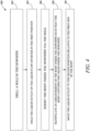
- FIGS. 3A, 3B, 3C, 3D and 4 together illustrate the various steps of a method 300 for retrofitting of the liquid flow diverter 100 with the downpipe 200.
- the method 300 for retrofitting the liquid flow diverter 100 with the downpipe 200 includes a first step 302 of drilling a hole 230 in the downpipe 200.
- the hole 230 may be drilled by any suitable process or tools known in the art. The present disclosure is not limited by choice of manner of drilling the hole 230 in any way.
- the method 300 further includes a second step 304 in which the liquid outlet 120 of the liquid flow diverter 100 is held by a user such that the liquid outlet 120 is adapted to be coupled with the body 110 of the liquid flow diverter 100.
- the body 110 includes the channel profile 112 between the first end 114 and the second end 116 such that the channel profile 112 allows flow of the liquid collected in the downpipe 200.
- the liquid outlet 120 is slidably coupled with the first end 114 of the body 110, such that the liquid outlet 120 is slidable relative to the first end 114 of the body 110 between the first position "P1" and the second position "P2".
- the liquid outlet 120 is adapted to be fluidly de-coupled with the first end 114 of the body 110 in the first position "P1".
- the liquid outlet 120 is adapted to be fluidly coupled with the first end 114 of the body 110 in the second position "P2".
- the liquid outlet 120 of the liquid flow diverter 100 is in the first position "P1".
- the method 300 further includes a third step 306 in which the liquid outlet 120 is in the first position "P1" relative to the first end 114 of the body 110.
- the third step 306 includes insertion of the body 110 inside the downpipe 200 via the hole 230.
- the method 300 includes a fourth step 308.
- an arrangement of the body 110 inside the downpipe 200 is manipulated such that the body 110 captures the liquid inside the downpipe 200.
- a fifth step 310 is executed.
- the liquid outlet 120 is moved to the second position "P2" relative to the first end 114 of the body 110.
- the liquid outlet 120 when in the second position "P2", completes the retrofitting of the liquid flow diverter 100 with the downpipe 100.
- the liquid outlet 120 aligns with the first end 114 of the body 110 such that the liquid collected in the body 110 may be accessed for use with various industrial and domestic applications.
- the method 300 is easy, convenient and safe to execute.
- the user may use the liquid outlet 120 as the handle to properly insert the body 110 of the liquid flow diverter 100 inside the downpipe 200. Thus, the user may not get in direct contact with the sharp drill hole 230 thereby preventing injuries.
- the retrofitting arrangement of the liquid flow diverter 100 with the downpipe 200 is additionally secured by a belt 128.
- the belt 128 may be made from any suitable material known in the art without limiting the scope of the present disclosure in any manner.
- the belt 128 may adapt to the shape of the downpipe 200 and consequently wrap around the outer surface 220 of the downpipe 200 to further strengthen the retrofitting arrangement of the liquid flow diverter 100 with the downpipe 200.
- the belt 128 includes a body portion 128A that wraps around the downpipe 200. Further, the belt 128 includes a pair of engaging elements 128B on each end of the body portion 128A such that the pair of engaging elements 128B are fastened to a pair of fingers 123 using a pair of caps 125 after the body portion 128A is wrapped around the downpipe 200.
- the pair of fingers 123 are provided as an extension on both ends of a ring 121, which is part of the liquid outlet 120.
- the belt 128 may be fastened or coupled to the liquid outlet 120 by any other means known in the art.
- the present disclosure provides the liquid flow diverter 100 that is fluidly coupled with the downpipe 200 via the liquid outlet 120.
- the liquid outlet 120 may further be fluidly coupled with the tap, or the liquid reservoir located even at a remote location, via the hose and the like for various domestic as well as industrial applications.
- the liquid outlet 120 is slidable with respect to the body 110 of the liquid flow diverter 120 and may be used as the handle to make retrofitting of the liquid flow diverter 100 with the downpipe 200 as an easy, convenient, efficient, and safe process.
Landscapes
- Engineering & Computer Science (AREA)
- General Engineering & Computer Science (AREA)
- Mechanical Engineering (AREA)
- Architecture (AREA)
- Civil Engineering (AREA)
- Structural Engineering (AREA)
- Devices For Dispensing Beverages (AREA)
- Lubrication Details And Ventilation Of Internal Combustion Engines (AREA)
- Multiple-Way Valves (AREA)
Claims (8)
- Flüssigkeitsströmungsumleiter (100) für ein Fallrohr (200), der Flüssigkeitsströmungsumleiter (100) umfassend:einen Körper (110), der ein Kanalprofil (112) zwischen einem ersten Ende (114) und einem zweiten Ende (116) definiert, wobei das Kanalprofil (112) eine Strömung einer Flüssigkeit darin ermöglicht; undeinen Flüssigkeitsauslass (120), der angepasst ist, um mit dem ersten Ende (114) des Körpers (110) gekoppelt zu werden, wobei der Flüssigkeitsauslass (120) eine Fluidkopplung des Flüssigkeitsströmungsumleiters (100) mit dem Fallrohr (200) ermöglicht;wobei der Flüssigkeitsauslass (120) mit dem ersten Ende (114) des Körpers (110) derart verschiebbar gekoppelt ist, dass der Flüssigkeitsauslass (120) relativ zu dem ersten Ende (114) des Körpers (110) zwischen einer ersten Position (P1) und einer zweiten Position (P2) verschiebbar ist;wobei der Flüssigkeitsauslass (120) angepasst ist, um von dem ersten Ende (114) des Körpers (110) in der ersten Position (P1) fluidisch entkoppelt zu werden; undwobei der Flüssigkeitsauslass (120) angepasst ist, um mit dem ersten Ende (114) des Körpers (110) in der zweiten Position (P2) fluidisch gekoppelt zu werden,wobei der Flüssigkeitsauslass (120) eine Vielzahl von Rippen (124) einschließt, wobei die Vielzahl von Rippen (124) es ermöglicht, den Flüssigkeitsauslass (120) mit dem ersten Ende (114) des Körpers (110) verschiebbar zu koppeln, und mit einer Vielzahl von Vorsprüngen (118) an dem ersten Ende (114) des Körpers (110) in Eingriff steht,wobeidieser Eingriff eine unlösbare Kopplung zwischen dem Körper (110) und dem Flüssigkeitsauslass (120) ausbildet.
- Flüssigkeitsströmungsumleiter (100) nach Anspruch 1, wobei in der ersten Position (P1) ein Ausströmen der Flüssigkeit aus dem Fallrohr (200) automatisch gestoppt wird.
- Flüssigkeitsströmungsumleiter (100) nach einem der vorstehenden Ansprüche, wobei in einer Zwischenposition das Ausströmen der Flüssigkeit aus dem Fallrohr (200) automatisch gestoppt wird, wobei die Zwischenposition eine beliebige Position des Flüssigkeitsauslasses (120) zwischen der ersten Position (P1) und der zweiten Position (P2) ist.
- Flüssigkeitsströmungsumleiter (100) nach einem der vorstehenden Ansprüche, wobei der Flüssigkeitsauslass (120) einen Ausguss (122) einschließt.
- Flüssigkeitsströmungsumleiter (100) nach einem der vorstehenden Ansprüche, wobei das Kanalprofil (112) eine Helixform aufweist.
- Verfahren (300) zum Nachrüsten eines Flüssigkeitsströmungsumleiters (100) mit einem Fallrohr (200), das Verfahren (300) umfassend:Bohren eines Lochs (230) in einem Fallrohr (200);Halten eines Flüssigkeitsauslasses (120) des Flüssigkeitsströmungsumleiters (100) derart, dass der Flüssigkeitsauslass (120) angepasst ist, um mit einem Körper (110) des Flüssigkeitsströmungsumleiters (100) gekoppelt zu werden, wobei der Körper (110) ein Kanalprofil (112) zwischen einem ersten Ende (114) und einem zweiten Ende (116) definiert;Einsetzen des Körpers (110) im Inneren des Fallrohrs (200) durch das Loch (230);Manipulieren einer Anordnung des Körpers (110) im Inneren des Fallrohrs (200) mit dem Flüssigkeitsauslass (120) derart, dass der Körper (110) Flüssigkeit im Inneren des Fallrohrs (200) auffängt;wobei der Flüssigkeitsauslass (120) mit dem ersten Ende (114) des Körpers (110) derart verschiebbar gekoppelt ist, dass der Flüssigkeitsauslass (120) relativ zu dem ersten Ende (114) des Körpers (110) zwischen einer ersten Position (P1) und einer zweiten Position (P2) verschiebbar ist;wobei der Flüssigkeitsauslass (120) angepasst ist, um von dem ersten Ende (114) des Körpers (110) in der ersten Position (P1) fluidisch entkoppelt zu werden;wobei der Flüssigkeitsauslass (120) angepasst ist, um mit dem ersten Ende (114) des Körpers (110) in der zweiten Position (P2) fluidisch gekoppelt zu werden; undwobei der Flüssigkeitsauslass (120), wenn er in der zweiten Position (P2) ist, das Nachrüsten des Flüssigkeitsströmungsumleiters (100) mit dem Fallrohr (200) abschließt,wobei der Flüssigkeitsauslass (120) eine Vielzahl von Rippen (124) einschließt, wobei die Vielzahl von Rippen (124) es ermöglicht, den Flüssigkeitsauslass (120) mit dem ersten Ende (114) des Körpers (110) verschiebbar zu koppeln, und mit einer Vielzahl von Vorsprüngen (118) an dem ersten Ende (114) des Körpers (110) in Eingriff steht,wobeidieser Eingriff eine unlösbare Kopplung zwischen dem Körper (110) und dem Flüssigkeitsauslass (120) ausbildet.
- Verfahren (300) nach Anspruch 6, wobei die Nachrüstungsanordnung des Flüssigkeitsströmungsumleiters (100) mit dem Fallrohr (200) zusätzlich durch einen Riemen (128) gesichert wird.
- Verfahren (300) nach Anspruch 6 und 7, wobei der Flüssigkeitsauslass (120) einen Ausguss (122) einschließt.
Priority Applications (3)
| Application Number | Priority Date | Filing Date | Title |
|---|---|---|---|
| EP22153017.3A EP4215686B1 (de) | 2022-01-24 | 2022-01-24 | Flüssigkeitsflussumleiter |
| CN202223551300.8U CN219300176U (zh) | 2022-01-24 | 2022-12-29 | 液流分流器 |
| CN202211711664.XA CN116480867A (zh) | 2022-01-24 | 2022-12-29 | 液流分流器及利用落水管改造液流分流器的方法 |
Applications Claiming Priority (1)
| Application Number | Priority Date | Filing Date | Title |
|---|---|---|---|
| EP22153017.3A EP4215686B1 (de) | 2022-01-24 | 2022-01-24 | Flüssigkeitsflussumleiter |
Publications (2)
| Publication Number | Publication Date |
|---|---|
| EP4215686A1 EP4215686A1 (de) | 2023-07-26 |
| EP4215686B1 true EP4215686B1 (de) | 2024-10-09 |
Family
ID=80001382
Family Applications (1)
| Application Number | Title | Priority Date | Filing Date |
|---|---|---|---|
| EP22153017.3A Active EP4215686B1 (de) | 2022-01-24 | 2022-01-24 | Flüssigkeitsflussumleiter |
Country Status (2)
| Country | Link |
|---|---|
| EP (1) | EP4215686B1 (de) |
| CN (2) | CN116480867A (de) |
Citations (1)
| Publication number | Priority date | Publication date | Assignee | Title |
|---|---|---|---|---|
| WO2023072459A1 (en) * | 2021-10-26 | 2023-05-04 | Husqvarna Ab | Liquid flow diverter |
Family Cites Families (3)
| Publication number | Priority date | Publication date | Assignee | Title |
|---|---|---|---|---|
| ES2420004T3 (es) * | 2010-06-23 | 2013-08-21 | Otto Graf Gmbh Kunststofferzeugnisse | Dispositivo para la recogida de agua de lluvia de un tubo bajante |
| DE102012022586A1 (de) * | 2012-11-20 | 2014-05-22 | Wisy Ag Haustechniksysteme, Filtertechnik | Regenwasserabscheider für ein Fallrohr |
| DE102013017979A1 (de) | 2013-11-29 | 2015-06-03 | 3P Technik Filtersysteme Gmbh | Wasserfangvorrichtung |
-
2022
- 2022-01-24 EP EP22153017.3A patent/EP4215686B1/de active Active
- 2022-12-29 CN CN202211711664.XA patent/CN116480867A/zh active Pending
- 2022-12-29 CN CN202223551300.8U patent/CN219300176U/zh active Active
Patent Citations (1)
| Publication number | Priority date | Publication date | Assignee | Title |
|---|---|---|---|---|
| WO2023072459A1 (en) * | 2021-10-26 | 2023-05-04 | Husqvarna Ab | Liquid flow diverter |
Also Published As
| Publication number | Publication date |
|---|---|
| EP4215686A1 (de) | 2023-07-26 |
| CN219300176U (zh) | 2023-07-04 |
| CN116480867A (zh) | 2023-07-25 |
Similar Documents
| Publication | Publication Date | Title |
|---|---|---|
| US20100193046A1 (en) | Rain water diverter | |
| US8156956B1 (en) | Refrigeration condensate line connectors | |
| US8528263B2 (en) | Rainwater diverter | |
| US4546789A (en) | Valved access fitting | |
| US10512225B2 (en) | Tree sap line connector and assembly | |
| US7410146B2 (en) | Drain valve with flow control | |
| US20210222412A1 (en) | Drain auger machine attachment for unclogging drains | |
| EP4215686A1 (de) | Flüssigkeitsflussumleiter | |
| US20060096639A1 (en) | Condensate drain tray connector | |
| GB2248262A (en) | Rainwater diverter | |
| US12320123B2 (en) | Liquid flow diverter | |
| EP2696007B1 (de) | Regenwasserfänger und Regenwasser-Fangsystem | |
| CN111108320B (zh) | 用于浇水工具的可见且可拆卸的过滤器 | |
| US20210238835A1 (en) | Drain pipe cleaning apparatus | |
| FI76162B (fi) | Monteringshjaelpanordning foer en insatsdel i en uppsamlingsbehaollare foer avloppsvatten. | |
| JP6916086B2 (ja) | 間接排水用継手 | |
| EP0899461B2 (de) | Tauchpumpe mit einer biegesteifen Auslassleitung | |
| US20120298156A1 (en) | Automatic Cleaning Device for a Liquid Container | |
| KR200475223Y1 (ko) | 싱크대용 수전금구 | |
| CN209733913U (zh) | 用于洗碗机的加水组件及具有其的洗碗机 | |
| CA2265361A1 (en) | Telescopic vent pipe for waste liquids | |
| US12467241B2 (en) | Rainwater reservoir | |
| GB2431429A (en) | Fluid drainage apparatus for pipe work | |
| GB2583709A (en) | Waste connector for vehicle | |
| CN214712438U (zh) | 一种拖把桶 |
Legal Events
| Date | Code | Title | Description |
|---|---|---|---|
| PUAI | Public reference made under article 153(3) epc to a published international application that has entered the european phase |
Free format text: ORIGINAL CODE: 0009012 |
|
| STAA | Information on the status of an ep patent application or granted ep patent |
Free format text: STATUS: REQUEST FOR EXAMINATION WAS MADE |
|
| 17P | Request for examination filed |
Effective date: 20221110 |
|
| AK | Designated contracting states |
Kind code of ref document: A1 Designated state(s): AL AT BE BG CH CY CZ DE DK EE ES FI FR GB GR HR HU IE IS IT LI LT LU LV MC MK MT NL NO PL PT RO RS SE SI SK SM TR |
|
| STAA | Information on the status of an ep patent application or granted ep patent |
Free format text: STATUS: EXAMINATION IS IN PROGRESS |
|
| 17Q | First examination report despatched |
Effective date: 20240621 |
|
| GRAP | Despatch of communication of intention to grant a patent |
Free format text: ORIGINAL CODE: EPIDOSNIGR1 |
|
| STAA | Information on the status of an ep patent application or granted ep patent |
Free format text: STATUS: GRANT OF PATENT IS INTENDED |
|
| GRAS | Grant fee paid |
Free format text: ORIGINAL CODE: EPIDOSNIGR3 |
|
| INTG | Intention to grant announced |
Effective date: 20240801 |
|
| GRAA | (expected) grant |
Free format text: ORIGINAL CODE: 0009210 |
|
| STAA | Information on the status of an ep patent application or granted ep patent |
Free format text: STATUS: THE PATENT HAS BEEN GRANTED |
|
| P01 | Opt-out of the competence of the unified patent court (upc) registered |
Free format text: CASE NUMBER: APP_45424/2024 Effective date: 20240806 |
|
| AK | Designated contracting states |
Kind code of ref document: B1 Designated state(s): AL AT BE BG CH CY CZ DE DK EE ES FI FR GB GR HR HU IE IS IT LI LT LU LV MC MK MT NL NO PL PT RO RS SE SI SK SM TR |
|
| REG | Reference to a national code |
Ref country code: CH Ref legal event code: EP |
|
| REG | Reference to a national code |
Ref country code: DE Ref legal event code: R096 Ref document number: 602022006560 Country of ref document: DE |
|
| REG | Reference to a national code |
Ref country code: IE Ref legal event code: FG4D |
|
| REG | Reference to a national code |
Ref country code: LT Ref legal event code: MG9D |
|
| REG | Reference to a national code |
Ref country code: NL Ref legal event code: MP Effective date: 20241009 |
|
| REG | Reference to a national code |
Ref country code: AT Ref legal event code: MK05 Ref document number: 1730749 Country of ref document: AT Kind code of ref document: T Effective date: 20241009 |
|
| PG25 | Lapsed in a contracting state [announced via postgrant information from national office to epo] |
Ref country code: NL Free format text: LAPSE BECAUSE OF FAILURE TO SUBMIT A TRANSLATION OF THE DESCRIPTION OR TO PAY THE FEE WITHIN THE PRESCRIBED TIME-LIMIT Effective date: 20241009 |
|
| PG25 | Lapsed in a contracting state [announced via postgrant information from national office to epo] |
Ref country code: NL Free format text: LAPSE BECAUSE OF FAILURE TO SUBMIT A TRANSLATION OF THE DESCRIPTION OR TO PAY THE FEE WITHIN THE PRESCRIBED TIME-LIMIT Effective date: 20241009 |
|
| PG25 | Lapsed in a contracting state [announced via postgrant information from national office to epo] |
Ref country code: HR Free format text: LAPSE BECAUSE OF FAILURE TO SUBMIT A TRANSLATION OF THE DESCRIPTION OR TO PAY THE FEE WITHIN THE PRESCRIBED TIME-LIMIT Effective date: 20241009 Ref country code: PT Free format text: LAPSE BECAUSE OF FAILURE TO SUBMIT A TRANSLATION OF THE DESCRIPTION OR TO PAY THE FEE WITHIN THE PRESCRIBED TIME-LIMIT Effective date: 20250210 Ref country code: IS Free format text: LAPSE BECAUSE OF FAILURE TO SUBMIT A TRANSLATION OF THE DESCRIPTION OR TO PAY THE FEE WITHIN THE PRESCRIBED TIME-LIMIT Effective date: 20250209 |
|
| PG25 | Lapsed in a contracting state [announced via postgrant information from national office to epo] |
Ref country code: FI Free format text: LAPSE BECAUSE OF FAILURE TO SUBMIT A TRANSLATION OF THE DESCRIPTION OR TO PAY THE FEE WITHIN THE PRESCRIBED TIME-LIMIT Effective date: 20241009 |
|
| PG25 | Lapsed in a contracting state [announced via postgrant information from national office to epo] |
Ref country code: BG Free format text: LAPSE BECAUSE OF FAILURE TO SUBMIT A TRANSLATION OF THE DESCRIPTION OR TO PAY THE FEE WITHIN THE PRESCRIBED TIME-LIMIT Effective date: 20241009 |
|
| PG25 | Lapsed in a contracting state [announced via postgrant information from national office to epo] |
Ref country code: ES Free format text: LAPSE BECAUSE OF FAILURE TO SUBMIT A TRANSLATION OF THE DESCRIPTION OR TO PAY THE FEE WITHIN THE PRESCRIBED TIME-LIMIT Effective date: 20241009 |
|
| PG25 | Lapsed in a contracting state [announced via postgrant information from national office to epo] |
Ref country code: NO Free format text: LAPSE BECAUSE OF FAILURE TO SUBMIT A TRANSLATION OF THE DESCRIPTION OR TO PAY THE FEE WITHIN THE PRESCRIBED TIME-LIMIT Effective date: 20250109 |
|
| PG25 | Lapsed in a contracting state [announced via postgrant information from national office to epo] |
Ref country code: LV Free format text: LAPSE BECAUSE OF FAILURE TO SUBMIT A TRANSLATION OF THE DESCRIPTION OR TO PAY THE FEE WITHIN THE PRESCRIBED TIME-LIMIT Effective date: 20241009 Ref country code: GR Free format text: LAPSE BECAUSE OF FAILURE TO SUBMIT A TRANSLATION OF THE DESCRIPTION OR TO PAY THE FEE WITHIN THE PRESCRIBED TIME-LIMIT Effective date: 20250110 Ref country code: AT Free format text: LAPSE BECAUSE OF FAILURE TO SUBMIT A TRANSLATION OF THE DESCRIPTION OR TO PAY THE FEE WITHIN THE PRESCRIBED TIME-LIMIT Effective date: 20241009 |
|
| PG25 | Lapsed in a contracting state [announced via postgrant information from national office to epo] |
Ref country code: PL Free format text: LAPSE BECAUSE OF FAILURE TO SUBMIT A TRANSLATION OF THE DESCRIPTION OR TO PAY THE FEE WITHIN THE PRESCRIBED TIME-LIMIT Effective date: 20241009 |
|
| PG25 | Lapsed in a contracting state [announced via postgrant information from national office to epo] |
Ref country code: RS Free format text: LAPSE BECAUSE OF FAILURE TO SUBMIT A TRANSLATION OF THE DESCRIPTION OR TO PAY THE FEE WITHIN THE PRESCRIBED TIME-LIMIT Effective date: 20250109 |
|
| PG25 | Lapsed in a contracting state [announced via postgrant information from national office to epo] |
Ref country code: SM Free format text: LAPSE BECAUSE OF FAILURE TO SUBMIT A TRANSLATION OF THE DESCRIPTION OR TO PAY THE FEE WITHIN THE PRESCRIBED TIME-LIMIT Effective date: 20241009 |
|
| PG25 | Lapsed in a contracting state [announced via postgrant information from national office to epo] |
Ref country code: DK Free format text: LAPSE BECAUSE OF FAILURE TO SUBMIT A TRANSLATION OF THE DESCRIPTION OR TO PAY THE FEE WITHIN THE PRESCRIBED TIME-LIMIT Effective date: 20241009 |
|
| REG | Reference to a national code |
Ref country code: DE Ref legal event code: R097 Ref document number: 602022006560 Country of ref document: DE |
|
| PG25 | Lapsed in a contracting state [announced via postgrant information from national office to epo] |
Ref country code: EE Free format text: LAPSE BECAUSE OF FAILURE TO SUBMIT A TRANSLATION OF THE DESCRIPTION OR TO PAY THE FEE WITHIN THE PRESCRIBED TIME-LIMIT Effective date: 20241009 |
|
| PG25 | Lapsed in a contracting state [announced via postgrant information from national office to epo] |
Ref country code: RO Free format text: LAPSE BECAUSE OF FAILURE TO SUBMIT A TRANSLATION OF THE DESCRIPTION OR TO PAY THE FEE WITHIN THE PRESCRIBED TIME-LIMIT Effective date: 20241009 |
|
| PG25 | Lapsed in a contracting state [announced via postgrant information from national office to epo] |
Ref country code: SK Free format text: LAPSE BECAUSE OF FAILURE TO SUBMIT A TRANSLATION OF THE DESCRIPTION OR TO PAY THE FEE WITHIN THE PRESCRIBED TIME-LIMIT Effective date: 20241009 |
|
| PG25 | Lapsed in a contracting state [announced via postgrant information from national office to epo] |
Ref country code: CZ Free format text: LAPSE BECAUSE OF FAILURE TO SUBMIT A TRANSLATION OF THE DESCRIPTION OR TO PAY THE FEE WITHIN THE PRESCRIBED TIME-LIMIT Effective date: 20241009 |
|
| PG25 | Lapsed in a contracting state [announced via postgrant information from national office to epo] |
Ref country code: IT Free format text: LAPSE BECAUSE OF FAILURE TO SUBMIT A TRANSLATION OF THE DESCRIPTION OR TO PAY THE FEE WITHIN THE PRESCRIBED TIME-LIMIT Effective date: 20241009 |
|
| PLBE | No opposition filed within time limit |
Free format text: ORIGINAL CODE: 0009261 |
|
| STAA | Information on the status of an ep patent application or granted ep patent |
Free format text: STATUS: NO OPPOSITION FILED WITHIN TIME LIMIT |
|
| REG | Reference to a national code |
Ref country code: CH Ref legal event code: PL |
|
| PG25 | Lapsed in a contracting state [announced via postgrant information from national office to epo] |
Ref country code: SE Free format text: LAPSE BECAUSE OF FAILURE TO SUBMIT A TRANSLATION OF THE DESCRIPTION OR TO PAY THE FEE WITHIN THE PRESCRIBED TIME-LIMIT Effective date: 20241009 |
|
| PG25 | Lapsed in a contracting state [announced via postgrant information from national office to epo] |
Ref country code: MC Free format text: LAPSE BECAUSE OF FAILURE TO SUBMIT A TRANSLATION OF THE DESCRIPTION OR TO PAY THE FEE WITHIN THE PRESCRIBED TIME-LIMIT Effective date: 20241009 Ref country code: LU Free format text: LAPSE BECAUSE OF NON-PAYMENT OF DUE FEES Effective date: 20250124 |
|
| 26N | No opposition filed |
Effective date: 20250710 |
|
| PG25 | Lapsed in a contracting state [announced via postgrant information from national office to epo] |
Ref country code: BE Free format text: LAPSE BECAUSE OF NON-PAYMENT OF DUE FEES Effective date: 20250131 |
|
| PG25 | Lapsed in a contracting state [announced via postgrant information from national office to epo] |
Ref country code: FR Free format text: LAPSE BECAUSE OF NON-PAYMENT OF DUE FEES Effective date: 20250131 |
|
| PG25 | Lapsed in a contracting state [announced via postgrant information from national office to epo] |
Ref country code: CH Free format text: LAPSE BECAUSE OF NON-PAYMENT OF DUE FEES Effective date: 20250131 |
|
| REG | Reference to a national code |
Ref country code: BE Ref legal event code: MM Effective date: 20250131 |
|
| PG25 | Lapsed in a contracting state [announced via postgrant information from national office to epo] |
Ref country code: IE Free format text: LAPSE BECAUSE OF NON-PAYMENT OF DUE FEES Effective date: 20250124 |
|
| PGFP | Annual fee paid to national office [announced via postgrant information from national office to epo] |
Ref country code: DE Payment date: 20251209 Year of fee payment: 5 |