EP4215036B1 - Antriebsstrang für die hin- und hergehenden messer eines mähdreschers - Google Patents
Antriebsstrang für die hin- und hergehenden messer eines mähdreschers Download PDFInfo
- Publication number
- EP4215036B1 EP4215036B1 EP22152509.0A EP22152509A EP4215036B1 EP 4215036 B1 EP4215036 B1 EP 4215036B1 EP 22152509 A EP22152509 A EP 22152509A EP 4215036 B1 EP4215036 B1 EP 4215036B1
- Authority
- EP
- European Patent Office
- Prior art keywords
- header
- drive shaft
- flywheel
- flange
- lateral drive
- Prior art date
- Legal status (The legal status is an assumption and is not a legal conclusion. Google has not performed a legal analysis and makes no representation as to the accuracy of the status listed.)
- Active
Links
Images




Classifications
-
- A—HUMAN NECESSITIES
- A01—AGRICULTURE; FORESTRY; ANIMAL HUSBANDRY; HUNTING; TRAPPING; FISHING
- A01D—HARVESTING; MOWING
- A01D34/00—Mowers; Mowing apparatus of harvesters
- A01D34/01—Mowers; Mowing apparatus of harvesters characterised by features relating to the type of cutting apparatus
- A01D34/02—Mowers; Mowing apparatus of harvesters characterised by features relating to the type of cutting apparatus having reciprocating cutters
- A01D34/30—Driving mechanisms for the cutters
- A01D34/32—Connecting-rods for knife-driving mechanisms
-
- A—HUMAN NECESSITIES
- A01—AGRICULTURE; FORESTRY; ANIMAL HUSBANDRY; HUNTING; TRAPPING; FISHING
- A01D—HARVESTING; MOWING
- A01D34/00—Mowers; Mowing apparatus of harvesters
- A01D34/01—Mowers; Mowing apparatus of harvesters characterised by features relating to the type of cutting apparatus
- A01D34/02—Mowers; Mowing apparatus of harvesters characterised by features relating to the type of cutting apparatus having reciprocating cutters
- A01D34/30—Driving mechanisms for the cutters
-
- A—HUMAN NECESSITIES
- A01—AGRICULTURE; FORESTRY; ANIMAL HUSBANDRY; HUNTING; TRAPPING; FISHING
- A01D—HARVESTING; MOWING
- A01D41/00—Combines, i.e. harvesters or mowers combined with threshing devices
- A01D41/12—Details of combines
- A01D41/14—Mowing tables
- A01D41/142—Header drives
-
- A—HUMAN NECESSITIES
- A01—AGRICULTURE; FORESTRY; ANIMAL HUSBANDRY; HUNTING; TRAPPING; FISHING
- A01D—HARVESTING; MOWING
- A01D34/00—Mowers; Mowing apparatus of harvesters
- A01D34/01—Mowers; Mowing apparatus of harvesters characterised by features relating to the type of cutting apparatus
- A01D34/02—Mowers; Mowing apparatus of harvesters characterised by features relating to the type of cutting apparatus having reciprocating cutters
- A01D34/13—Cutting apparatus
- A01D34/14—Knife-bars
-
- A—HUMAN NECESSITIES
- A01—AGRICULTURE; FORESTRY; ANIMAL HUSBANDRY; HUNTING; TRAPPING; FISHING
- A01D—HARVESTING; MOWING
- A01D69/00—Driving mechanisms or parts thereof for harvesters or mowers
- A01D69/06—Gearings
Definitions
- the present invention is related to self-propelled combine harvesters, in particular to a driveline that connects a power shaft of the harvester to a set of reciprocating knives of a combine header coupled at the front of the harvester.
- a combine harvester includes a main self-propelled body mounted on four wheels and comprising an engine to drive the self-propelled movement of the harvester, and further comprising a feeder at the front of the harvester, a threshing system, a cleaning arrangement, a grain tank and a crop residue spreading apparatus.
- a removable header is attached at the front of the harvester, the header comprising movable knives at the front of a header table, a reel for guiding crops towards the knives, and transportation means such as an auger or a set of draper belts, to move the cut crops towards the centre of the header where the crops enter the feeder.
- the knives of the header are part of a single or double cutterbar, that further comprises stationary counterknives, wherein the movable knives undergo a reciprocating movement or a continuous movement relative to the counterknives, thereby cutting the crops at a given height above ground level.
- the movement of a set of reciprocating knives is typically driven by a driveline that is coupled to a power shaft of the harvester, and that comprises a laterally placed gearbox near the back side of the header and a transmission near the front side of the header, where a rotating part of the transmission is converted into a reciprocating motion.
- the transmission may be a belt or chain transmission, and the conversion may be realized by a wobble box.
- the joint that couples the telescopic shaft to the planetary gearbox is mounted inside a cup-shaped flywheel that is integral with the input axle of the planetary gearbox. This makes this joint however very difficult to access. Also, the flywheel can be rather heavy on larger machines, which can make it difficult to handle the flywheel during installation or maintenance.
- Patent publication document EP3669633 discloses a combine harvester wherein the forward-directed driveline from the combine is coupled to the transversely oriented header drive axle through a transverse gearbox that is mounted on a moveable cradle frame onto which the header is mounted.
- the housing of the gearbox or at least the portion of the housing comprising the input axle of the gearbox is rotatably arranged relative to the cradle frame, about a rotation axis oriented transversely to the combine's forward direction.
- a mechanical link is furthermore provided between the rotatable gearbox housing (portion) and the feeder housing, configured to control the orientation of the input axle of the transverse gearbox, so as to maintain the alignment of said input axle relative to the driveline of the combine.
- Patent publication document US2012/317951 discloses a combine harvester including a feeder and a detachable header, the feeder comprising at least one or more rotatable cams and hooks, rotatable around a common axis, the cams being arranged to gradually lower the distance between the feeder and the header, by rotating the cams away from the header, the hooks being arranged to grip a bar or pin located on the header as the cams are being rotated away from the header, thereby securing the header to the feeder.
- the disclosure includes an example of a universal joint comprising two forks and a cross-piece, wherein one fork is integral with or fixed to a flange.
- Patent publication document US2016/044870 discloses a straw chopper for a combine including a rotor mounted in a housing with blades for chopping the discharge material onto a material spreading assembly.
- the rotor is driven by a drive transmission from an output drive shaft of the drive system of the combine harvester including first a right angle gear box connected to the drive shaft, a second right angle gear box connected to the rotor and a single drive shaft communicating drive from the first gear box to the second gear box.
- the disclosure includes an example of a universal joint comprising two forks and a cross-piece, wherein one fork is integral with or fixed to a flange.
- Patent publication document US4127981 discloses a crop harvesting machine including a mobile frame, a header movably suspended from the frame, a pair of upper and lower conditioner rolls rotatably mounted on the frame rearwardly of the header, and drive means for operating the conditioner rolls and the cutterbar and reel of the header.
- the drive means includes a gearbox assembly mounted on the frame and having rotary input drive transmission means and a transversely extending rotary output shaft drivingly coupled to the input means.
- the drive mechanism for operating the cutterbar includes a wobble box equipped with a flywheel.
- Patent publication document US3729907 discloses a tractor drawn and powered agricultural machine, such as a mower-conditioner for hay-like crops, comprising a main frame having a pair of spaced apart side walls between which a sickle mower, a tine reel, a pair of conditioning rolls, a crop gathering hood and windrowing means, and a pair of transport wheel assemblies are mounted.
- Operating power from the tractor is supplied through a rotatable power take-off shaft and clutches to a transmission unit comprising enclosed gears which is mounted on the main frame outboard of one side wall.
- the transmission unit drives the sickle mower through a reciprocating pitman drive which includes a break-away bolt which breaks if the sickle-bar jams.
- the pitman drive also includes a flywheel to which one end of a pitman rod is pivotably connected.
- the invention aims to solve the above-described problems and achieves this aim by a header comprising a driveline arrangement as described in the appended claims.
- the present invention is thus related to a combine header comprising a header frame and a set of knives at the front of the header configured to undergo a reciprocating transverse movement, i.e. transverse with respect to the forward direction of travel of the harvester when the header is coupled thereto.
- the header comprises a driveline for driving said reciprocating movement, the driveline including a transverse drive shaft at the back of the header frame, a bevel gearbox, a lateral drive shaft and a transmission in the vicinity of the knives and configured to directly drive the knife motion.
- the lateral drive shaft is coupled respectively to the bevel gearbox and the transmission by a first and second universal joint.
- the inlet axle of the transmission is integral with or fixed to a flywheel configured to stabilize the rotation of the lateral drive shaft.
- the second universal joint comprises two orthogonal forks coupled by a cross-piece.
- One of the forks is integral with or fixed to a flange that is attached to a surface of the flywheel that faces the lateral drive shaft.
- the flange is configured to contribute to the stabilizing function of the flywheel when the flange is attached to said surface
- the assembly of the flywheel and the flange forms an enlarged operational flywheel. Due to its function, the flywheel is an axisymmetric body with respect to the flywheel's rotation axis. As the flange contributes to the stabilizing function, the flange is also an axisymmetric body about said rotation axis.
- the flange may for example be bolted to the surface of the flywheel that faces the lateral drive shaft.
- the attachment of the universal joint to the flywheel by way of the flange enables easy access to the universal joint as well as providing a construction wherein the weight of the flange contributes to the weight of the flywheel when the driveline is operational.
- the flywheel has a base portion and an axisymmetric sidewall that is oriented towards the lateral drive shaft and/or towards the transmission.
- the flywheel comprises a sidewall oriented towards the lateral drive shaft so as to form a cup-shaped interior space and the flange is a ring-shaped flange attached to the top surface of said sidewall, with the second universal joint at least partially located inside said cup-shaped inner space.
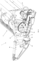
- FIG. 1 illustrates a combine header 1 according to one exemplary embodiment of the invention.
- the construction of a combine header is well-known and the header is therefore not shown in its entirety.
- the header comprises a frame 2 having a back wall 3 and two side walls 4, only one of which is shown in the image.
- the floor of the header is formed by an extendable and retractable header table 5, at the front of which is mounted a cutterbar 6 comprising a row of stationary counterknives 7 and a set of movable cutter knives 8 configured to undergo a reciprocating movement relative to the counterknives 7.
- the extension or retraction of the header table 5 (and thereby the cutterbar 6) relative to the frame 2 may be actuated by multiple variable length actuators mounted underneath the header table 5 and not visible in the drawing, but known as such.
- the side wall 4 has a rear portion 4a that is part of the header frame 2, and a front portion 4b that is integral with or fixed to the header table 5 so as to extend or retract together with said table 5 relative to the frame
- a rotatable auger 9 is visible as well, configured to move crops towards the centre of the header 1, where the crops enter the feeder section (not shown) of the harvester.
- a second auger with oppositely inclined auger blades is present on the other side (not shown) of the header 1.
- the driveline for driving the reciprocating movement of the knives 8 is now described in more detail.
- the terms 'inlet axle' and 'outlet axle' are defined within the present context as respective axles of gearboxes or other types of transmissions which are part of the driveline.
- the wording 'inlet' and 'outlet' are to be understood as referring to the direction of the power transfer along the driveline, starting at the back of the header where power is taken up from a power source, towards the front of the header, where power is consumed by the movement of the knives.
- the driveline comprises a transverse drive shaft 15 mounted at the back of the header 1.
- This shaft 15 is referred to as transverse in the sense that it is oriented transversally with respect to the header's forward direction of travel through a field of crops when the header 1 is mounted at the front of an operational combine harvester.
- the transverse shaft 15 is coupled at its first end (not shown) to a power shaft of the combine.
- the transverse shaft 15 comprises a pair of sprockets 16 and 17, which are the driving sprockets of a first and second chain drive.
- the first chain drive is configured to drive the rotation of the auger 9, through a larger sprocket 18 coupled to the auger's rotation axle.
- the first chain drive further comprises a tensioning sprocket 19.
- the first chain drive is not in fact part of the driveline for driving the knife movement, but it is driven by the same transverse shaft 15.
- the auger 9 could be driven in another way, for example by a driveline that is completely separate from the
- the second chain drive comprises besides the sprocket 17, a further sprocket 20 located above said sprocket 17.
- Said upper sprocket 20 is coupled to the inlet axle of a bevel gearbox 25 mounted on a support bracket 26 that is fixed to the frame 2.
- the bevel gearbox 25 comprises said inlet axle (not visible) and an outlet axle 27, coupled to the first end of a lateral drive shaft 28 by a first universal joint 29.
- the drive shaft 28 is termed 'lateral' in the sense that it is located at the side of the header frame 2 and oriented from the back area of the header 1 towards the front area of the header 1, i.e. in the general direction of the header's forward movement through a field when it is coupled to an operational harvester.
- the driveline for the knife movement may comprise further universal joints or other couplings upstream of the components described so far, i.e. between a power shaft of the harvester and the bevel gearbox 25.
- Such upstream joints and couplings are not shown in detail and are not the subject of the present invention.
- this upstream part of the driveline may be in accordance with any currently known driveline design.
- the bevel gearbox 25 itself is a component that is known per se, and any suitable type of known bevel gearbox may be applied in the driveline of the invention, comprising a set of bevel gears configured to transform the rotation about a first axis to a rotation about a second axis oriented essentially perpendicularly to the first axis.
- the bevel gearbox 25 is coupled directly to the transverse drive shaft 15 instead of being coupled thereto via the chain drive comprising the sprockets 17 and 20.
- the lateral drive shaft 28 is a telescopic drive shaft that can extend or retract in length when the header table 5 is extended or retracted.
- a telescopic drive shaft is known as such and any known type of telescopic drive shaft can be implemented in a header according to embodiments of the invention that include an extendable and retractable header table.
- the invention is however not limited to a header comprising an extendable header table, but applies also to header having a fixed header table.
- the lateral drive shaft 28 can be a standard (i.e. non-telescopic) drive shaft.
- the first end of the lateral drive shaft 28 is coupled to the outlet axle 27 of the bevel gearbox 25 via the first universal joint 29.
- the second end of the lateral drive shaft 28 is coupled to the inlet axle (not visible in Figure 1 ) of a planetary gearbox 30 mounted on a support bracket 31 in the vicinity of the cutterbar 6, via a second universal joint 35.
- the support bracket 31 is part of the extendable front portion 4b of the header sidewall 4.
- the planetary gearbox 30 comprises an outlet axle (not visible) that is coupled to the knives 8 in order to actuate the reciprocating movement of the knives.
- the planetary gearbox 30 as such and the way in which it is coupled to the knives 8 may be in accordance with known configurations, and these aspects are therefore not described here in detail.
- a flywheel 36 is fixed to or integral with the inlet axle of the planetary gearbox 30.
- the second universal joint 35 and the way in which it is coupled to the flywheel 36 forms the main focus of the present invention.
- a more detailed image of the second joint 35 and the manner in which it is coupled to the planetary gearbox 30 according to one particular embodiment is illustrated in the section view shown in Figure 2 .
- the internal rotatable components of the planetary gearbox 30 are not shown, and only the housing 30a of said gearbox is visible, as well as the bolts 37 by which this housing 30a is attached to the bracket 31 (not shown in Figure 2 ).
- the flywheel 36 comprises a hollow central axle 38 configured to receive therein the inlet axle (not shown in Figure 2 ) of the planetary gearbox 30. Said inlet axle is fixed to the central axle 38 and thereby to the flywheel 36 as such.
- the flywheel 36 itself comprises a base portion 36a with the hollow axle 38 in the centre thereof, a sidewall comprising a first sidewall portion 36b rising up perpendicularly with respect to the base portion 36a in the general direction of the lateral drive shaft 28 and a second sidewall portion 36c oriented in the direction of the planetary gearbox 30.
- the first and second sidewall 'portions' 36b and 36c are hereafter referred to as first and second 'sidewalls' of the flywheel 36.
- the flywheel's function is to stabilize the rotation of one or more rotating components of the driveline, in particular the lateral drive shaft 28. Due to this stabilizing function, the flywheel 36 is an axisymmetric body with respect to its rotation axis 36d.
- the base portion 36a and the first sidewall 36b are forming a cup shape with the base portion 36a defining the bottom of the cup and the first sidewall 36b defining the interior space of the cup. Side openings 39 are provided in the sidewall 36b, for the supply of lubricant to the interior of the cup shape.
- the second sidewall 36c forms an oppositely oriented cup shape. However in this particular embodiment, the second sidewall 36c is optional and could be omitted.
- the second universal joint 35 comprises a first fork 40 and a second fork 41, which are interconnected by a cross-shaped centre piece 42 and with the second fork 41 oriented at a right angle to the first fork 40, the forks being pivotably coupled to the respective legs of the centre piece 42.
- the second fork 41 is integral with a ring-shaped flange 43 that is removably fixed to the top surface 34 of the sidewall 36b of the flywheel 36.
- the flange 43 is mounted flush against the top surface 34 of the sidewall 36b and secured thereto by screw connections 44.
- the piece comprising the flange 43 and the second fork 41 of the universal joint 35 is shown in more detail.
- the flange has an inner circular circumference 45 and an outer circular circumference 46. It is seen that the legs of the fork 41 are attached to the flange 43 in the vicinity of the inner circumference 45.
- the flange 43 has a first side plane 47 facing the flywheel 36 and a second side plane 48 facing the lateral drive shaft 28.
- the fork 41 protrudes outward from the first side plane 47, so that the joint 35 is essentially located inside the interior space of the cup defined by the base portion 36a and the sidewall 36b.
- the second fork 41 is integral with the flange 43, this flange itself is not a part of the universal joint 35.
- the flange 43 further comprises a rim portion 49 along the inner circumference, which fits into a recess 50 along the inner circumference of the top of the sidewall 36b and that is helpful for aligning the flange 43 to the top surface 34 of the sidewall 36b. Said rim portion 49 is however optional and could be omitted.
- the piece shown in Figures 4a and 4b comprising both the flange 43 and the second fork 41 is preferably produced as an integrally cast or forged piece, but could also be obtained by producing the legs of the fork 41 and attaching them to the ring-shaped flange 43 by welding.
- the configuration described so far has a number of advantages over the prior art.
- the universal joint 35 is coupled to the top surface 34 of the flywheel's sidewall 36b and not to the base portion 36a of the flywheel, which facilitates removal and re-mounting operations performed during maintenance or repair, as the connection between the joint 35 and the flywheel 36 is more easily accessible.
- the weight of the flange 43 is added to the weight of the flywheel 36, i.e. the 'operational' flywheel is mainly formed of the assembly of the flywheel 36 and the flange 43. As a consequence, the dimensions of the flywheel 36 as such can be reduced without diminishing its stabilizing effect.
- the specific embodiment wherein the joint 35 (comprising the forks 40 and 41 but not the flange 43) is mounted inside the flywheel 36 is moreover advantageous in that it maximizes the distance between the first and second joints 29 and 35.
- This is particularly useful in the case of the header 1 shown in the drawings, i.e. a header provided with an extendable and retractable header table 5.
- this header type it is important to obtain the highest possible extension length for a given header size. The higher the distance between the joints 29 and 35, the higher the obtainable extension length without requiring more complex and expensive measures such as the use of a three-piece telescopic shaft or a header design with longer sidewalls 4.
- the invention is not limited to the case where the joint 35 is located inside the cup-shape defined by the base portion 36a and the sidewall 36b of the flywheel 36.
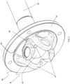
- the first two advantages i.e. easy accessibility and reduction of the flywheel weight, are also obtained by a second embodiment illustrated in Figures 5 and 6 , wherein the second joint 35 is located outside and adjacent to the flywheel 36, while still being coupled to a ring-shaped flange 51 that is bolted to the top surface 34 of the flywheel's sidewall 36b.
- the second fork 41 of the joint is again integral with the flange 51 and attached to said flange 51 in the vicinity of the inner circumference 45.
- the width W between the inner and outer circumferences 45 and 46 of the flange 51 is however larger in this case, as the first fork 40 is not required to enter into the interior of the cup-shape defined by the base portion 36a and the sidewall 36b of the flywheel 36.
- An equivalent to the configuration shown in Figure 6 may include a closed disc-shaped flange instead of a ring-shaped flange, with the second fork 41 integral with or attached to the centre of the disc.
- the flywheel comprises only the base portion 36a and the second sidewall 36c, and the flange 51 or a closed disc-shaped flange is attached to the base portion 36a, at the side opposite the sidewall 36c.
- the invention is not limited to a flywheel having either a single or double cup shape.
- the flange 43 or 51 (or a closed disc-shape flange) is removably attached to a surface of the flywheel that faces the lateral drive shaft 28.
- the flange is a closed disc, the flywheel could even be a solid axisymmetric body.
- the planetary gearbox 30 is just one example of a transmission that can be applied in a header according to the invention, and that is capable of transforming the rotation of the lateral drive shaft 28 into a reciprocating movement of the knives 8.
- Another transmission that can be used in a header according to the invention is a wobble box.
- the outer diameter of the flange 43 or 51 could be somewhat larger than the outer diameter of the flywheel 36 so that the outer circumference of the flange extends beyond the diameter of the flywheel 36.
- the outer diameter of the flange 43 or 51 could be somewhat smaller than the outer diameter of the flywheel 36, and the top surface 34 of the flywheel's sidewall 36b could be provided with a rim portion so that the flange 43 or 51 may be fitted into said rim portion for easy alignment of the flange to the flywheel.
- the flange 43 or 51 is preferably directly attached to the surface 34 of the flywheel facing the lateral drive shaft 28, i.e. lying flush against and in contact with said surface 34, as illustrated in the drawings. There could however be an intermediate ring or an additional flange or a number of spacers in between the flange 43 or 51 and the surface 34 of the flywheel.
- the flange 43 or 51 could be part of a larger piece that is attached to the flywheel 36, such as for example a cup-shaped piece of which the flange 43 or 51 is the bottom portion and further comprising a sidewall that is placed over the flywheel 36, for example overlapping the flywheel's sidewall 36b.
- a cup-shaped piece could then be attached to the flywheel by bolt connections through the flange 43 or 51 and/or by bolt connections through the overlapping sidewalls.
- the second universal joint 35 is preferably fully located inside the interior space of the cup-shape formed by the base portion 36a and the sidewall 36b of the flywheel, but the joint 35 could also be partially located in said interior space, if the fork 41 protrudes outward from the side plane 47 over a smaller distance than shown in the drawings, or if one or more spacers are added between the flange 43 and the top surface 34 of the flywheel's sidewall 36b.
- any of the embodiments described above can be present on both sides of header 1, when the header is provided with a double cutterbar, i.e. a set of knives 8 on each side, the two sets spanning the complete width of the header 1, each set of knives being actuated by respective drivelines arranged laterally on the two sides of the header.
- the inventive aspects described above are applicable to the driveline of each of the knife sets.
- a combine harvester of the invention is equipped with a header comprising a single or double driveline in accordance with any of the above-described embodiments or their equivalents.
- the header is operationally coupled to the harvester, meaning that the transverse drive shaft 15 is rotatably coupled to a power shaft of the harvester, so that the driveline is powered by a power source of the harvester.
Landscapes
- Life Sciences & Earth Sciences (AREA)
- Environmental Sciences (AREA)
- Harvester Elements (AREA)
- Engineering & Computer Science (AREA)
- General Engineering & Computer Science (AREA)
- Zoology (AREA)
- Mechanical Engineering (AREA)
Claims (11)
- Mähdrescher-Vorsatz (1) mit einem Vorsatz-Rahmen (2) und einem Antriebsstrang zum Antreiben einer Hin- und Herbewegung eines Messersatzes (8), der an der Vorderseite des Mähdrescher-Vorsatzes angebracht ist, wobei der Antriebsstrang umfasst:- eine quer verlaufende Antriebswelle (15) auf der Rückseite des Mähdrescher-Vorsatzes,- ein Kegelradgetriebe (25), das eine Eingangsachse, die mit der quer verlaufenden Antriebswelle (15) drehbar verbunden ist, und eine Ausgangsachse (27) aufweist,- eine seitliche Antriebswelle (28), die in Bezug auf den Vorsatz-Rahmen (2) seitlich angeordnet ist, wobei die seitliche Antriebswelle (28) ein erstes Ende und ein zweites Ende aufweist,- ein Getriebe (30), das eine Eingangsachse und eine Ausgangsachse umfasst, wobei die Ausgangsachse mit dem Messersatz (8) verbunden ist,und wobei:- die seitliche Antriebswelle (28) an ihrem ersten Ende mit der Ausgangsachse (27) des Kegelradgetriebes (25) mittels eines ersten Kardangelenks (29) verbunden ist,- die seitliche Antriebswelle (28) an ihrem zweiten Ende mit der Eingangsachse des Getriebes (30) mittels eines zweiten Kardangelenks (35) verbunden ist,- der Antriebsstrang ein Schwungrad (36) umfasst, das um eine zentrale Rotationsachse (36d) drehbar ist und mit der Eingangsachse des Getriebes (30) integral ausgebildet oder an dieser befestigt ist, wobei das Schwungrad (36) ein axialsymmetrischer Körper in Bezug auf die zentrale Rotationsachse (36d) ist, wobei das Schwungrad dazu eingerichtet ist, die Rotation der seitlichen Antriebswelle (28) zu stabilisieren,- das zweite Kardangelenk (35) eine erste Gabel (40), die an der seitlichen Antriebswelle (28) angebracht ist, eine zweite Gabel (41), die in Bezug auf die erste Gabel senkrecht orientiert ist und an der Eingangsachse des Getriebes (30) angebracht ist, und ein Querstück (42) umfasst, wobei die Gabeln relativ zu den Schenkeln des Querstücks (42) drehbar sind,dadurch gekennzeichnet, dass die zweite Gabel (41) an der Eingangsachse des Getriebes (30) angebracht ist, indem sie integral mit einem Flansch (43, 51) ausgebildet oder an diesem angebracht ist, der an einer Oberfläche (34) des Schwungrads (36) abnehmbar angebracht ist, die zu der seitlichen Antriebswelle (28) zeigt, und wobei der Flansch (43, 51) ebenfalls ein axialsymmetrischer Körper in Bezug auf die Rotationsachse des Schwungrads ist, sodass der Flansch dazu eingerichtet ist, zu der stabilisierenden Funktion des Schwungrads (36) beizutragen, wenn der Flansch an der Oberfläche (34) angebracht ist.
- Mähdrescher-Vorsatz (1) nach Anspruch 1, wobei das Schwungrad (36) einen Basisabschnitt (36a) und eine Seitenwand (36b, 36c) aufweist, wobei der Basisabschnitt integral mit der Eingangsachse des Getriebes (30) ausgebildet ist oder an dieser angebracht ist, wobei die Seitenwand, ausgehend von dem Basisabschnitt (36a), zu der seitlichen Antriebswelle (28) und/oder zu dem Getriebe (30) hin ausgerichtet ist.
- Mähdrescher-Vorsatz (1) nach Anspruch 2, wobei zumindest ein Abschnitt (36b) der Seitenwand derart zu der seitlichen Antriebswelle (28) hin ausgerichtet ist, dass eine Becherform gebildet wird, wobei der Basisabschnitt (36a) den Boden des Bechers definiert und der Abschnitt (36b) der Seitenwand den Innenraum des Bechers definiert, und wobei der Flansch (43, 51) als ein ebener Ring geformt ist, der eine erste seitliche Ebene (47), die dem Schwungrad (36) zugewandt und an der oberen Fläche (34) des Abschnitts (36b) der Seitenwand angebracht ist, die zu der seitlichen Antriebswelle (28) hin ausgerichtet ist, und eine zweite seitliche Ebene (48) aufweist, die zu der seitlichen Antriebswelle (28) hin ausgerichtet ist,
und wobei die Schenkel der zweiten Gabel (41):- an dem Flansch (43) angebracht sind,- von der ersten oder zweiten seitlichen Ebene (47, 48) des Flansches (43) nach außen ragen. - Mähdrescher-Vorsatz (1) nach Anspruch 3, wobei die Schenkel der zweiten Gabel (41) des zweiten Kardangelenks (35) von der ersten seitlichen Ebene (47) derart nach außen, d.h. in die Richtung des Innenraums des Bechers, ragen, dass das zweite Kardangelenk (35) zumindest teilweise innerhalb des Innenraums angebracht ist.
- Mähdrescher-Vorsatz (1) nach Anspruch 3, wobei die Schenkel der zweiten Gabel (41) des zweiten Kardangelenks (35) von der zweiten seitlichen Ebene (48) derart nach außen, d.h. in die Richtung der seitlichen Antriebswelle (28), ragen, dass das zweite Kardangelenk (35) neben dem Schwungrad (36) angebracht ist.
- Mähdrescher-Vorsatz (1) nach Anspruch 1 oder 2, wobei der Flansch als eine Scheibe geformt ist und wobei die zweite Gabel (41) des zweiten Kardangelenks (35) an der Scheibe an der Seite der seitlichen Antriebswelle (28) derart angebracht ist, dass das zweite Kardangelenk (35) neben dem Schwungrad (36) angebracht ist.
- Mähdrescher-Vorsatz (1) nach einem der vorhergehenden Ansprüche, wobei die Messer (8) Teil eines Messerbalkens (6) sind, der an der Vorderseite eines aus- und einziehbaren Mähdrescher-Vorsatztisches (5) angebracht ist, und wobei die seitliche Antriebswelle (28) eine teleskopartige Antriebswelle ist.
- Mähdrescher-Vorsatz (1) nach einem der vorhergehenden Ansprüche, wobei das Getriebe (30) ein Planetengetriebe ist.
- Mähdrescher-Vorsatz (1) nach einem der Ansprüche 1 bis 7, wobei das Getriebe (30) ein Taumelgetriebe ist.
- Mähdrescher-Vorsatz (1) nach einem der vorhergehenden Ansprüche, umfassend einem Riemen- oder Kettenantrieb (17, 20), der die querverlaufende Antriebswelle (15) mit der Eingangsachse des Kegelradgetriebes (25) drehbar verbindet.
- Mähdrescher mit einem Vorsatz (1) nach einem der vorhergehenden Ansprüche.
Priority Applications (2)
| Application Number | Priority Date | Filing Date | Title |
|---|---|---|---|
| EP22152509.0A EP4215036B1 (de) | 2022-01-20 | 2022-01-20 | Antriebsstrang für die hin- und hergehenden messer eines mähdreschers |
| US18/098,362 US12550815B2 (en) | 2022-01-20 | 2023-01-18 | Driveline for the reciprocating knives of a combine header |
Applications Claiming Priority (1)
| Application Number | Priority Date | Filing Date | Title |
|---|---|---|---|
| EP22152509.0A EP4215036B1 (de) | 2022-01-20 | 2022-01-20 | Antriebsstrang für die hin- und hergehenden messer eines mähdreschers |
Publications (2)
| Publication Number | Publication Date |
|---|---|
| EP4215036A1 EP4215036A1 (de) | 2023-07-26 |
| EP4215036B1 true EP4215036B1 (de) | 2024-11-13 |
Family
ID=80113239
Family Applications (1)
| Application Number | Title | Priority Date | Filing Date |
|---|---|---|---|
| EP22152509.0A Active EP4215036B1 (de) | 2022-01-20 | 2022-01-20 | Antriebsstrang für die hin- und hergehenden messer eines mähdreschers |
Country Status (2)
| Country | Link |
|---|---|
| US (1) | US12550815B2 (de) |
| EP (1) | EP4215036B1 (de) |
Families Citing this family (1)
| Publication number | Priority date | Publication date | Assignee | Title |
|---|---|---|---|---|
| CA219260S (en) * | 2022-09-14 | 2024-06-27 | Claas Kgaa Mbh | Rape cutting knife |
Family Cites Families (11)
| Publication number | Priority date | Publication date | Assignee | Title |
|---|---|---|---|---|
| US3729907A (en) * | 1972-02-25 | 1973-05-01 | Gehl Co | Mower conditioner |
| US4127981A (en) * | 1977-01-17 | 1978-12-05 | Sperry Rand Corporation | Drive means for a crop harvesting machine |
| US20050086919A1 (en) * | 2003-10-28 | 2005-04-28 | Stiefvater Thomas L. | Wobble drive for windrower header |
| US20080271426A1 (en) * | 2006-02-10 | 2008-11-06 | Agco Corporation | Draper belt with crop-retaining rib |
| BE1019635A3 (nl) * | 2010-02-02 | 2012-09-04 | Cnh Belgium Nv | Landbouwmachine met automatische koppeling. |
| DE102012107681A1 (de) | 2012-08-21 | 2014-03-20 | Claas Selbstfahrende Erntemaschinen Gmbh | Getriebe für den Antrieb eines Mähmessers einer Erntemaschine |
| DE102012107682A1 (de) | 2012-08-21 | 2014-03-20 | Claas Selbstfahrende Erntemaschinen Gmbh | Schneidwerk für eine selbstfahrende Erntemaschine |
| DE102014003880A1 (de) * | 2014-03-19 | 2015-09-24 | Claas Selbstfahrende Erntemaschinen Gmbh | Schneidwerk für eine Erntemaschine |
| DE102014215163A1 (de) * | 2014-08-01 | 2016-02-04 | Deere & Company | Exzentertrieb |
| EP3017682B1 (de) * | 2014-08-14 | 2019-03-06 | Dean Mayerle | Antriebssystem für einen strohhäcksler eines mähdreschers |
| EP3669633B1 (de) * | 2018-12-18 | 2022-02-09 | CNH Industrial Belgium NV | Kopfantriebsmechanismus für einen mähdrescher |
-
2022
- 2022-01-20 EP EP22152509.0A patent/EP4215036B1/de active Active
-
2023
- 2023-01-18 US US18/098,362 patent/US12550815B2/en active Active
Also Published As
| Publication number | Publication date |
|---|---|
| US20230225242A1 (en) | 2023-07-20 |
| EP4215036A1 (de) | 2023-07-26 |
| US12550815B2 (en) | 2026-02-17 |
Similar Documents
| Publication | Publication Date | Title |
|---|---|---|
| US10426089B2 (en) | Feeder having lateral tilt for an agricultural harvesting combine | |
| US7805919B2 (en) | Offset epicyclic sickle drive for a header of an agricultural plant cutting machine | |
| US20090145097A1 (en) | Compact knife head assembly, bearing and eccentric for a sickle drive for a header of an agricultural plant cutting machine | |
| US8291685B2 (en) | Wide cut rotary harvester having helper roll with auger flighting | |
| US20120174550A1 (en) | Auxiliary drive motor for hay conditioner on a windrower header | |
| US12610889B2 (en) | Harvesting attachment with height-adjustable cross-feeding auger | |
| CA3002835C (en) | Draper header for attachment to a harvesting machine | |
| EP4215036B1 (de) | Antriebsstrang für die hin- und hergehenden messer eines mähdreschers | |
| CN101779545A (zh) | 玉米青贮茎穗兼收秸杆还田自走收获机的设计方法 | |
| CN208387303U (zh) | 一种多功能灌木收获机 | |
| JP2013153656A (ja) | コンバイン | |
| US3139717A (en) | Forage harvester | |
| KR101031516B1 (ko) | 다목적 작물 수확기 | |
| US3324638A (en) | Windrower sickle drive | |
| CN109168575B (zh) | 联合收割机 | |
| CN104135847B (zh) | 联合收割机 | |
| JP5843632B2 (ja) | コンバイン | |
| EP0165624A1 (de) | Mähmaschine | |
| JP2014117265A (ja) | コンバイン | |
| KR102343273B1 (ko) | 쵸퍼형 원형 베일러 | |
| WO2021020568A1 (ja) | コンバイン | |
| CN207151249U (zh) | 谷物联合收割机及其脱粒分离装置 | |
| JP2014068586A (ja) | コンバイン | |
| JP7274968B2 (ja) | コンバイン | |
| JP2013153654A (ja) | コンバイン |
Legal Events
| Date | Code | Title | Description |
|---|---|---|---|
| PUAI | Public reference made under article 153(3) epc to a published international application that has entered the european phase |
Free format text: ORIGINAL CODE: 0009012 |
|
| STAA | Information on the status of an ep patent application or granted ep patent |
Free format text: STATUS: THE APPLICATION HAS BEEN PUBLISHED |
|
| AK | Designated contracting states |
Kind code of ref document: A1 Designated state(s): AL AT BE BG CH CY CZ DE DK EE ES FI FR GB GR HR HU IE IS IT LI LT LU LV MC MK MT NL NO PL PT RO RS SE SI SK SM TR |
|
| STAA | Information on the status of an ep patent application or granted ep patent |
Free format text: STATUS: REQUEST FOR EXAMINATION WAS MADE |
|
| 17P | Request for examination filed |
Effective date: 20240126 |
|
| RBV | Designated contracting states (corrected) |
Designated state(s): AL AT BE BG CH CY CZ DE DK EE ES FI FR GB GR HR HU IE IS IT LI LT LU LV MC MK MT NL NO PL PT RO RS SE SI SK SM TR |
|
| GRAP | Despatch of communication of intention to grant a patent |
Free format text: ORIGINAL CODE: EPIDOSNIGR1 |
|
| STAA | Information on the status of an ep patent application or granted ep patent |
Free format text: STATUS: GRANT OF PATENT IS INTENDED |
|
| RIC1 | Information provided on ipc code assigned before grant |
Ipc: A01D 69/00 20060101ALI20240430BHEP Ipc: A01D 34/30 20060101AFI20240430BHEP |
|
| INTG | Intention to grant announced |
Effective date: 20240604 |
|
| GRAS | Grant fee paid |
Free format text: ORIGINAL CODE: EPIDOSNIGR3 |
|
| GRAA | (expected) grant |
Free format text: ORIGINAL CODE: 0009210 |
|
| STAA | Information on the status of an ep patent application or granted ep patent |
Free format text: STATUS: THE PATENT HAS BEEN GRANTED |
|
| AK | Designated contracting states |
Kind code of ref document: B1 Designated state(s): AL AT BE BG CH CY CZ DE DK EE ES FI FR GB GR HR HU IE IS IT LI LT LU LV MC MK MT NL NO PL PT RO RS SE SI SK SM TR |
|
| REG | Reference to a national code |
Ref country code: GB Ref legal event code: FG4D |
|
| REG | Reference to a national code |
Ref country code: CH Ref legal event code: EP |
|
| REG | Reference to a national code |
Ref country code: IE Ref legal event code: FG4D |
|
| REG | Reference to a national code |
Ref country code: DE Ref legal event code: R096 Ref document number: 602022007589 Country of ref document: DE |
|
| REG | Reference to a national code |
Ref country code: LT Ref legal event code: MG9D |
|
| REG | Reference to a national code |
Ref country code: NL Ref legal event code: MP Effective date: 20241113 |
|
| PG25 | Lapsed in a contracting state [announced via postgrant information from national office to epo] |
Ref country code: HR Free format text: LAPSE BECAUSE OF FAILURE TO SUBMIT A TRANSLATION OF THE DESCRIPTION OR TO PAY THE FEE WITHIN THE PRESCRIBED TIME-LIMIT Effective date: 20241113 Ref country code: PT Free format text: LAPSE BECAUSE OF FAILURE TO SUBMIT A TRANSLATION OF THE DESCRIPTION OR TO PAY THE FEE WITHIN THE PRESCRIBED TIME-LIMIT Effective date: 20250313 Ref country code: IS Free format text: LAPSE BECAUSE OF FAILURE TO SUBMIT A TRANSLATION OF THE DESCRIPTION OR TO PAY THE FEE WITHIN THE PRESCRIBED TIME-LIMIT Effective date: 20250313 |
|
| PG25 | Lapsed in a contracting state [announced via postgrant information from national office to epo] |
Ref country code: FI Free format text: LAPSE BECAUSE OF FAILURE TO SUBMIT A TRANSLATION OF THE DESCRIPTION OR TO PAY THE FEE WITHIN THE PRESCRIBED TIME-LIMIT Effective date: 20241113 Ref country code: NL Free format text: LAPSE BECAUSE OF FAILURE TO SUBMIT A TRANSLATION OF THE DESCRIPTION OR TO PAY THE FEE WITHIN THE PRESCRIBED TIME-LIMIT Effective date: 20241113 |
|
| REG | Reference to a national code |
Ref country code: AT Ref legal event code: MK05 Ref document number: 1740863 Country of ref document: AT Kind code of ref document: T Effective date: 20241113 |
|
| PG25 | Lapsed in a contracting state [announced via postgrant information from national office to epo] |
Ref country code: BG Free format text: LAPSE BECAUSE OF FAILURE TO SUBMIT A TRANSLATION OF THE DESCRIPTION OR TO PAY THE FEE WITHIN THE PRESCRIBED TIME-LIMIT Effective date: 20241113 |
|
| PG25 | Lapsed in a contracting state [announced via postgrant information from national office to epo] |
Ref country code: ES Free format text: LAPSE BECAUSE OF FAILURE TO SUBMIT A TRANSLATION OF THE DESCRIPTION OR TO PAY THE FEE WITHIN THE PRESCRIBED TIME-LIMIT Effective date: 20241113 |
|
| PG25 | Lapsed in a contracting state [announced via postgrant information from national office to epo] |
Ref country code: NO Free format text: LAPSE BECAUSE OF FAILURE TO SUBMIT A TRANSLATION OF THE DESCRIPTION OR TO PAY THE FEE WITHIN THE PRESCRIBED TIME-LIMIT Effective date: 20250213 |
|
| PG25 | Lapsed in a contracting state [announced via postgrant information from national office to epo] |
Ref country code: LV Free format text: LAPSE BECAUSE OF FAILURE TO SUBMIT A TRANSLATION OF THE DESCRIPTION OR TO PAY THE FEE WITHIN THE PRESCRIBED TIME-LIMIT Effective date: 20241113 Ref country code: AT Free format text: LAPSE BECAUSE OF FAILURE TO SUBMIT A TRANSLATION OF THE DESCRIPTION OR TO PAY THE FEE WITHIN THE PRESCRIBED TIME-LIMIT Effective date: 20241113 Ref country code: GR Free format text: LAPSE BECAUSE OF FAILURE TO SUBMIT A TRANSLATION OF THE DESCRIPTION OR TO PAY THE FEE WITHIN THE PRESCRIBED TIME-LIMIT Effective date: 20250214 |
|
| PG25 | Lapsed in a contracting state [announced via postgrant information from national office to epo] |
Ref country code: PL Free format text: LAPSE BECAUSE OF FAILURE TO SUBMIT A TRANSLATION OF THE DESCRIPTION OR TO PAY THE FEE WITHIN THE PRESCRIBED TIME-LIMIT Effective date: 20241113 |
|
| PG25 | Lapsed in a contracting state [announced via postgrant information from national office to epo] |
Ref country code: RS Free format text: LAPSE BECAUSE OF FAILURE TO SUBMIT A TRANSLATION OF THE DESCRIPTION OR TO PAY THE FEE WITHIN THE PRESCRIBED TIME-LIMIT Effective date: 20250213 |
|
| PG25 | Lapsed in a contracting state [announced via postgrant information from national office to epo] |
Ref country code: SM Free format text: LAPSE BECAUSE OF FAILURE TO SUBMIT A TRANSLATION OF THE DESCRIPTION OR TO PAY THE FEE WITHIN THE PRESCRIBED TIME-LIMIT Effective date: 20241113 |
|
| PG25 | Lapsed in a contracting state [announced via postgrant information from national office to epo] |
Ref country code: DK Free format text: LAPSE BECAUSE OF FAILURE TO SUBMIT A TRANSLATION OF THE DESCRIPTION OR TO PAY THE FEE WITHIN THE PRESCRIBED TIME-LIMIT Effective date: 20241113 |
|
| PG25 | Lapsed in a contracting state [announced via postgrant information from national office to epo] |
Ref country code: EE Free format text: LAPSE BECAUSE OF FAILURE TO SUBMIT A TRANSLATION OF THE DESCRIPTION OR TO PAY THE FEE WITHIN THE PRESCRIBED TIME-LIMIT Effective date: 20241113 |
|
| PG25 | Lapsed in a contracting state [announced via postgrant information from national office to epo] |
Ref country code: RO Free format text: LAPSE BECAUSE OF FAILURE TO SUBMIT A TRANSLATION OF THE DESCRIPTION OR TO PAY THE FEE WITHIN THE PRESCRIBED TIME-LIMIT Effective date: 20241113 |
|
| PG25 | Lapsed in a contracting state [announced via postgrant information from national office to epo] |
Ref country code: SK Free format text: LAPSE BECAUSE OF FAILURE TO SUBMIT A TRANSLATION OF THE DESCRIPTION OR TO PAY THE FEE WITHIN THE PRESCRIBED TIME-LIMIT Effective date: 20241113 |
|
| PG25 | Lapsed in a contracting state [announced via postgrant information from national office to epo] |
Ref country code: CZ Free format text: LAPSE BECAUSE OF FAILURE TO SUBMIT A TRANSLATION OF THE DESCRIPTION OR TO PAY THE FEE WITHIN THE PRESCRIBED TIME-LIMIT Effective date: 20241113 |
|
| REG | Reference to a national code |
Ref country code: DE Ref legal event code: R097 Ref document number: 602022007589 Country of ref document: DE |
|
| REG | Reference to a national code |
Ref country code: CH Ref legal event code: PL |
|
| PG25 | Lapsed in a contracting state [announced via postgrant information from national office to epo] |
Ref country code: SE Free format text: LAPSE BECAUSE OF FAILURE TO SUBMIT A TRANSLATION OF THE DESCRIPTION OR TO PAY THE FEE WITHIN THE PRESCRIBED TIME-LIMIT Effective date: 20241113 |
|
| PG25 | Lapsed in a contracting state [announced via postgrant information from national office to epo] |
Ref country code: MC Free format text: LAPSE BECAUSE OF FAILURE TO SUBMIT A TRANSLATION OF THE DESCRIPTION OR TO PAY THE FEE WITHIN THE PRESCRIBED TIME-LIMIT Effective date: 20241113 Ref country code: LU Free format text: LAPSE BECAUSE OF NON-PAYMENT OF DUE FEES Effective date: 20250120 |
|
| PLBE | No opposition filed within time limit |
Free format text: ORIGINAL CODE: 0009261 |
|
| STAA | Information on the status of an ep patent application or granted ep patent |
Free format text: STATUS: NO OPPOSITION FILED WITHIN TIME LIMIT |
|
| PG25 | Lapsed in a contracting state [announced via postgrant information from national office to epo] |
Ref country code: BE Free format text: LAPSE BECAUSE OF NON-PAYMENT OF DUE FEES Effective date: 20250131 |
|
| PG25 | Lapsed in a contracting state [announced via postgrant information from national office to epo] |
Ref country code: CH Free format text: LAPSE BECAUSE OF NON-PAYMENT OF DUE FEES Effective date: 20250131 |
|
| 26N | No opposition filed |
Effective date: 20250814 |
|
| REG | Reference to a national code |
Ref country code: BE Ref legal event code: MM Effective date: 20250131 |
|
| PG25 | Lapsed in a contracting state [announced via postgrant information from national office to epo] |
Ref country code: IE Free format text: LAPSE BECAUSE OF NON-PAYMENT OF DUE FEES Effective date: 20250120 |
|
| PGFP | Annual fee paid to national office [announced via postgrant information from national office to epo] |
Ref country code: DE Payment date: 20260127 Year of fee payment: 5 |
|
| PGFP | Annual fee paid to national office [announced via postgrant information from national office to epo] |
Ref country code: IT Payment date: 20260123 Year of fee payment: 5 |
|
| PGFP | Annual fee paid to national office [announced via postgrant information from national office to epo] |
Ref country code: FR Payment date: 20260126 Year of fee payment: 5 |