EP4212688A1 - Locking mechanism and electronic device - Google Patents
Locking mechanism and electronic device Download PDFInfo
- Publication number
- EP4212688A1 EP4212688A1 EP22175439.3A EP22175439A EP4212688A1 EP 4212688 A1 EP4212688 A1 EP 4212688A1 EP 22175439 A EP22175439 A EP 22175439A EP 4212688 A1 EP4212688 A1 EP 4212688A1
- Authority
- EP
- European Patent Office
- Prior art keywords
- housing
- locking mechanism
- engaging recess
- hook
- hinge
- Prior art date
- Legal status (The legal status is an assumption and is not a legal conclusion. Google has not performed a legal analysis and makes no representation as to the accuracy of the status listed.)
- Granted
Links
Images



Classifications
-
- H—ELECTRICITY
- H05—ELECTRIC TECHNIQUES NOT OTHERWISE PROVIDED FOR
- H05K—PRINTED CIRCUITS; CASINGS OR CONSTRUCTIONAL DETAILS OF ELECTRIC APPARATUS; MANUFACTURE OF ASSEMBLAGES OF ELECTRICAL COMPONENTS
- H05K5/00—Casings, cabinets or drawers for electric apparatus
- H05K5/02—Details
- H05K5/0208—Interlock mechanisms; Means for avoiding unauthorised use or function, e.g. tamperproof
-
- E—FIXED CONSTRUCTIONS
- E05—LOCKS; KEYS; WINDOW OR DOOR FITTINGS; SAFES
- E05C—BOLTS OR FASTENING DEVICES FOR WINGS, SPECIALLY FOR DOORS OR WINDOWS
- E05C19/00—Other devices specially designed for securing wings, e.g. with suction cups
- E05C19/10—Hook fastenings; Fastenings in which a link engages a fixed hook-like member
- E05C19/12—Hook fastenings; Fastenings in which a link engages a fixed hook-like member pivotally mounted around an axis
- E05C19/14—Hook fastenings; Fastenings in which a link engages a fixed hook-like member pivotally mounted around an axis with toggle action
- E05C19/145—Hook fastenings; Fastenings in which a link engages a fixed hook-like member pivotally mounted around an axis with toggle action flush
-
- E—FIXED CONSTRUCTIONS
- E05—LOCKS; KEYS; WINDOW OR DOOR FITTINGS; SAFES
- E05C—BOLTS OR FASTENING DEVICES FOR WINGS, SPECIALLY FOR DOORS OR WINDOWS
- E05C19/00—Other devices specially designed for securing wings, e.g. with suction cups
- E05C19/10—Hook fastenings; Fastenings in which a link engages a fixed hook-like member
- E05C19/12—Hook fastenings; Fastenings in which a link engages a fixed hook-like member pivotally mounted around an axis
- E05C19/14—Hook fastenings; Fastenings in which a link engages a fixed hook-like member pivotally mounted around an axis with toggle action
-
- E—FIXED CONSTRUCTIONS
- E05—LOCKS; KEYS; WINDOW OR DOOR FITTINGS; SAFES
- E05B—LOCKS; ACCESSORIES THEREFOR; HANDCUFFS
- E05B17/00—Accessories in connection with locks
- E05B17/0054—Fraction or shear lines; Slip-clutches, resilient parts or the like for preventing damage when forced or slammed
- E05B17/0062—Fraction or shear lines; Slip-clutches, resilient parts or the like for preventing damage when forced or slammed with destructive disengagement
-
- E—FIXED CONSTRUCTIONS
- E05—LOCKS; KEYS; WINDOW OR DOOR FITTINGS; SAFES
- E05B—LOCKS; ACCESSORIES THEREFOR; HANDCUFFS
- E05B65/00—Locks or fastenings for special use
- E05B65/10—Locks or fastenings for special use for panic or emergency doors
- E05B65/102—Locks or fastenings for special use for panic or emergency doors opening under pressure on the surface of the door itself
- E05B65/1026—Locks or fastenings for special use for panic or emergency doors opening under pressure on the surface of the door itself by a yieldable or breakable bolt or striker
-
- G—PHYSICS
- G06—COMPUTING OR CALCULATING; COUNTING
- G06F—ELECTRIC DIGITAL DATA PROCESSING
- G06F1/00—Details not covered by groups G06F3/00 - G06F13/00 and G06F21/00
- G06F1/16—Constructional details or arrangements
- G06F1/1613—Constructional details or arrangements for portable computers
- G06F1/1633—Constructional details or arrangements of portable computers not specific to the type of enclosures covered by groups G06F1/1615 - G06F1/1626
- G06F1/1656—Details related to functional adaptations of the enclosure, e.g. to provide protection against EMI, shock, water, or to host detachable peripherals like a mouse or removable expansions units like PCMCIA cards, or to provide access to internal components for maintenance or to removable storage supports like CDs or DVDs, or to mechanically mount accessories
-
- H—ELECTRICITY
- H05—ELECTRIC TECHNIQUES NOT OTHERWISE PROVIDED FOR
- H05K—PRINTED CIRCUITS; CASINGS OR CONSTRUCTIONAL DETAILS OF ELECTRIC APPARATUS; MANUFACTURE OF ASSEMBLAGES OF ELECTRICAL COMPONENTS
- H05K5/00—Casings, cabinets or drawers for electric apparatus
- H05K5/02—Details
- H05K5/0217—Mechanical details of casings
-
- E—FIXED CONSTRUCTIONS
- E05—LOCKS; KEYS; WINDOW OR DOOR FITTINGS; SAFES
- E05B—LOCKS; ACCESSORIES THEREFOR; HANDCUFFS
- E05B15/00—Other details of locks; Parts for engagement by bolts of fastening devices
- E05B15/0086—Toggle levers
Definitions
- the application relates in general to a locking mechanism, and in particular, to a locking mechanism for connecting two housings.
- an embodiment of the invention provides a locking device for connecting a first housing to a second housing, wherein the first housing and the second housing are arranged along a first direction.
- the locking mechanism includes a first hook, a second hook, a movable member, and a driving member.
- the first hook and the second hook are affixed to the first housing, and respectively have a first engaging recess and a second engaging recess.
- the first engaging recess and the second engaging recess are arranged along the first direction.
- the movable portion has an engaging portion.
- the driving member is connected to the second housing and the movable member, and is configured to drive the movable member to move relative to the second housing. When the first housing is affixed to the second housing via the locking mechanism, the engaging portion is accommodated in the first engaging recess.
- the first engaging recess in the first direction, is disposed between the first housing and the second engaging recess.
- the width of the second engaging recess is greater than or equal to the width of the first engaging recess. In some embodiments, in a third direction, the length of the second engaging recess is greater than the length of the first engaging recess, wherein the third direction is perpendicular to the first direction and the second direction.
- the distance between the bottom of the second engaging recess and an end of the second hook is greater than the distance between the bottom of the first engaging recess and the bottom of the second engaging recess.
- a portion of the first hook is received in the second engaging recess.
- the first hook and the second hook are integrally formed as one piece.
- the engaging portion when the first housing is affixed to the second housing via the locking mechanism, the engaging portion is in contact with the first hook.
- the driving member includes an operating member, a first hinge, and a second hinge.
- the first hinge is pivotally connected to the movable member and the operating member
- the second hinge is pivotally connected to the second housing and the operating member.
- the first hinge is parallel to the second hinge.
- An embodiment of the invention also provides an electronic device, including a first housing, a second housing, and the aforementioned locking mechanism.
- first and second features are formed in direct contact
- additional features may be formed between the first and second features, such that the first and second features may not be in direct contact
- spatially relative terms such as “beneath,” “below,” “lower,” “above,” “upper” and the like, may be used herein for ease of description to describe one element or feature's relationship to another element(s) or feature(s) as illustrated in the figures.
- the spatially relative terms are intended to encompass different orientations of the device in use or operation in addition to the orientation depicted in the figures.
- the apparatus may be otherwise oriented (rotated 90 degrees or at other orientations) and the spatially relative descriptors used herein may likewise be interpreted accordingly.
- Fig. 1 is a schematic diagram of an electronic device C according to an embodiment of the invention
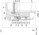
- Fig. 2 is a cross-sectional view taken along the line A-A in Fig. 1
- the electronic device C includes a first housing 10, a second housing 20, at least one locking mechanism 30, and at least one electronic member 40, wherein the first housing 10 is detachably connected to the second housing 20, and an accommodating space S is formed between them.
- the electronic member 40 can be accommodated in the accommodating space S.
- the electronic member 40 can include a battery, a transformer, a motor, an internal combustion engine, a printed circuit board, a capacitor, and/or a power component (such as an insulated gate bipolar transistor (IGBT) or a metal-oxide-semiconductor (MOS) transistor, but it is not limited thereto).
- a power component such as an insulated gate bipolar transistor (IGBT) or a metal-oxide-semiconductor (MOS) transistor, but it is not limited thereto.
- IGBT insulated gate bipolar transistor
- MOS metal-oxide-semiconductor
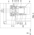
- Fig. 3 is a front view of the locking mechanism 30 in Fig. 1 .
- the locking mechanism 30 primarily includes a fixed member 100, a driving member 200, and a movable member 300.
- the fixed member 100 is affixed to the first housing 10, and includes a first hook 110 and a second hook 120.
- the first hook 110 and the second hook 120 can respectively form a first engaging recess 111 and a second engaging recess 121.
- the first hook 110 and the second hook 120 are arranged along the arrangement direction of the first housing 10 and the second housing 20 when they are engaged.
- the first hook 110 and the second hook 120 are arranged along the first direction D1.
- the first engaging recess 111 and the second engaging recess 121 are therefore arranged along the first direction D1.
- the first hook 110 and the second hook 120 are extended downward from the first housing 10, and the second hook 120 is extended further down than the first hook 110. Therefore, in the first direction D1, the first engaging recess 111 is disposed between the first housing 10 and the second engaging recess 121.
- the width W2 of the second engaging recess 121 is greater than or equal to the width W1 of the first engaging recess 111.
- the length L2 of the second engaging recess 121 is greater than the length L1 of the first engaging recess 111.
- the end E2 of the second hook 120 can be extended upward to align with or exceed the end E1 of the first hook 110.
- the distance between the end E2 of the second hook 120 and the bottom B2 of the second engaging recess 121 is greater than the distance between the bottom B1 of the first engaging recess 111 and the bottom B2 of the second engaging recess 121.
- a depression portion 122 can be formed on the second hook 120, and the end E1 of the first hook 110 can be received in this depression portion 122.
- at least a portion of the first hook 110 can be received in the second engaging recess 121.
- first hook 110 and the second hook 120 are formed by cutting and/or bending the fixed member 100 having a single plate, so that they can be integrally formed as one piece.
- first hook 110 and the second hook 120 can be two separated members, and respectively affixed to the first housing 10.
- the driving member 200 includes an operating member 210, a first hinge 220, and a second hinge 230
- the movable member 300 includes a main body 310, an engaging portion 320, and a case 330.
- the first hinge 220 passes through the case 330 of the movable member 300 and pivotally connects to the main body 310 and the operating member 210.
- the first hinge 220 and the second hinge 230 are parallel to each other.
- the main body 310 of the movable member 300 is a longitudinal member. One end of the main body 310 is pivotally connected to the first hinge 220, and the other end of the main body 310 is connected to the engaging portion 320.
- the engaging portion 320 is a cylinder.
- the appearance of the engaging portion 320 is not limited, and can be adjusted as required.
- the case 330 covers the main body 310 to prevent the main body 310 from impact with the external object and causing damage.
- the operating method of the locking mechanism 30 is discussed below. As shown in Fig. 4A , when the first housing 10 is affixed to the second housing 20 through the locking mechanism 30, the engaging portion 320 is accommodated in the first engaging recess 111 and in contact with the first hook 110, the first hinge 220 is in a first position, and the second hinge 230 is disposed between the engaging portion 320 and the first hinge 220.
- the user wants to separate the first housing 10 from the second housing 20
- he or she can pull the operating member 210 to drive the first hinge 220 to move around the second hinge 230 from the first position to the second position.
- the first hinge 220 is disposed between the engaging portion 320 and the second hinge 230, so that the engaging portion 320 can be released from the first engaging recess 111, and the user can separate the first housing 10 and the second housing 20.
- the locking mechanism 30 When the user wants to use the locking mechanism 30 to affix the first housing 10 to the second housing 20, he or she can push the operating member 210 reversely after the first housing 10 is connected to the second housing 20, and the first hinge 220 can move around the second hinge 230 from the second position to the first position ( Fig. 4A ).
- the electronic member 40 for example, the battery, the transformer, the motor, the internal combustion engine, the printed circuit board, the capacitor, and/or the power component (such as the insulated gate bipolar transistor (IGBT) or the metal-oxide-semiconductor (MOS) transistor)
- the power component such as the insulated gate bipolar transistor (IGBT) or the metal-oxide-semiconductor (MOS) transistor
- the generated gas may cause the first hook 110 to break.
- the first housing 10 moves away from the second housing 20 due to the generated gas, so that the engaging portion 320 of the movable member 300 enters the second engaging recess 121 and is in contact with the second hook 120.
- the second hook 120 can withstand more pressure than the first hook 110. Moreover, when the first hook 110 is broken and the first housing 10 moves due to the gas, the first housing 10 is hooked by the second hook 120 that is in the lower position, so that a gap G can be formed between the first housing 10 and the second housing 20. The gas can be slowly exhausted from the gap G, and the impacting force on the first housing 10 can be gradually decreased. Therefore, it can prevent the first housing 10 from directly departing from the second housing 20.
- the engaging portion 320 can directly enter the second engaging recess 121 when the first hook 110 is broken. The situation that the engaging portion 320 does not enter the second engaging recess 121 can be prevented.
- the first housing 10 when the exhaust process of the aforementioned gas is finished, the first housing 10 can move back to be connected to the second housing 20. It should be noted that, since the end E2 of the second hook 120 in this embodiment is extended upward to align with or exceed the end E1 of the first hook 110, the engaging portion 320 can be still disposed in the second engaging recess 121.
- the locking mechanism 30 can still restrict the moving range of the first housing 10 in the first direction D1, the second direction D2 and the third direction D3 relative to the second housing 20. Therefore, it can be ensured that the first housing 10 does not depart from the second housing 20 after the first hook 110 is broken.
- a power switch (not shown) that is electrically connected to the electronic member 40 can be disposed on the first housing 10 or the second housing 20 of the electronic device C.
- the power switch can be also disposed in a specific position away from the electronic device C and electrically connected to the electronic member 40.
- a locking mechanism for connecting a first housing to a second housing, wherein the first housing and the second housing are arranged along a first direction.
- the locking mechanism includes a first hook, a second hook, a movable member, and a driving member.
- the first hook and the second hook are affixed to the first housing, and respectively has a first engaging recess and a second engaging recess.
- the first engaging recess and the second engaging recess are arranged along the first direction.
- the movable portion has an engaging portion.
- the driving member is connected to the second housing and the movable member, and is configured to drive the movable member to move relative to the second housing. When the first housing is affixed to the second housing via the locking mechanism, the engaging portion is accommodated in the first engaging recess.
- an electronic device including the aforementioned locking mechanism is also provided
Landscapes
- Engineering & Computer Science (AREA)
- Computer Hardware Design (AREA)
- Theoretical Computer Science (AREA)
- General Engineering & Computer Science (AREA)
- Mechanical Engineering (AREA)
- Microelectronics & Electronic Packaging (AREA)
- Human Computer Interaction (AREA)
- Physics & Mathematics (AREA)
- General Physics & Mathematics (AREA)
- Emergency Management (AREA)
- Computer Security & Cryptography (AREA)
- Business, Economics & Management (AREA)
- Casings For Electric Apparatus (AREA)
- Electric Double-Layer Capacitors Or The Like (AREA)
- Battery Mounting, Suspending (AREA)
Abstract
Description
- This application claims the benefit of
China Patent Application No. 202210030465.6, filed Jan. 12, 2022 - The application relates in general to a locking mechanism, and in particular, to a locking mechanism for connecting two housings.
- With the development of technology, various electronic apparatuses and mechanical apparatuses have been widely used in industry or daily life. However, the use of some electronic apparatuses and/or mechanical apparatuses may have risks. For example, the apparatus may explode if it breaks down, and the force of impact due to the explosion may strike the housing of the container used to receive the electronic apparatuses and mechanical apparatuses, and this housing may fly away. If this shrapnel strikes a human body, it may cause physical damage, or even be life-threatening. Therefore, how to address the aforementioned problem has become an important issue.
- To address the deficiencies of conventional products, an embodiment of the invention provides a locking device for connecting a first housing to a second housing, wherein the first housing and the second housing are arranged along a first direction. The locking mechanism includes a first hook, a second hook, a movable member, and a driving member. The first hook and the second hook are affixed to the first housing, and respectively have a first engaging recess and a second engaging recess. The first engaging recess and the second engaging recess are arranged along the first direction. The movable portion has an engaging portion. The driving member is connected to the second housing and the movable member, and is configured to drive the movable member to move relative to the second housing. When the first housing is affixed to the second housing via the locking mechanism, the engaging portion is accommodated in the first engaging recess.
- In some embodiments, in the first direction, the first engaging recess is disposed between the first housing and the second engaging recess.
- In some embodiments, in a second direction that is perpendicular to the first direction, the width of the second engaging recess is greater than or equal to the width of the first engaging recess. In some embodiments, in a third direction, the length of the second engaging recess is greater than the length of the first engaging recess, wherein the third direction is perpendicular to the first direction and the second direction.
- In some embodiments, in the first direction, the distance between the bottom of the second engaging recess and an end of the second hook is greater than the distance between the bottom of the first engaging recess and the bottom of the second engaging recess.
- In some embodiments, a portion of the first hook is received in the second engaging recess.
- In some embodiments, the first hook and the second hook are integrally formed as one piece.
- In some embodiments, when the first housing is affixed to the second housing via the locking mechanism, the engaging portion is in contact with the first hook.
- In some embodiments, the driving member includes an operating member, a first hinge, and a second hinge. The first hinge is pivotally connected to the movable member and the operating member, and the second hinge is pivotally connected to the second housing and the operating member. The first hinge is parallel to the second hinge. When the first housing is affixed to the second housing via the locking mechanism, the first hinge is in a first position, and the second hinge is disposed between the engaging portion and the first hinge. When the first hinge moves around the second hinge from the first position to a second position, the first hinge is disposed between the engaging portion and the second hinge.
- An embodiment of the invention also provides an electronic device, including a first housing, a second housing, and the aforementioned locking mechanism.
- The invention can be more fully understood by reading the subsequent detailed description and examples with references made to the accompanying drawings, wherein:
-
Fig. 1 is a schematic diagram of an electronic device according to an embodiment of the invention; -
Fig. 2 is a cross-sectional view taken along the line A-A inFig. 1 ; -
Fig. 3 is a front view of a locking mechanism according to an embodiment of the invention; -
Fig. 4A is a schematic diagram that represents that a first hinge is in a first position according to an embodiment of the invention; -
Fig. 4B is a schematic diagram that represents that the first hinge moves from the first position to a second position according to an embodiment of the invention; -
Fig. 5A is a schematic diagram that represents that an engaging portion is accommodated in a second engaging recess when the first hook is broken according to an embodiment of the invention; and -
Fig. 5B is a schematic diagram that represents that the first hook is broken and the first housing is engaged to the second housing according to an embodiment of the invention. - The making and using of the embodiments of the electronic device and the locking mechanism are discussed in detail below. It should be appreciated, however, that the embodiments provide many applicable inventive concepts that can be embodied in a wide variety of specific contexts. The specific embodiments discussed are merely illustrative of specific ways to make and use the embodiments, and do not limit the scope of the disclosure.
- Unless defined otherwise, all technical and scientific terms used herein have the same meaning as commonly understood by one of ordinary skill in the art to which this invention belongs. It should be appreciated that each term, which is defined in a commonly used dictionary, should be interpreted as having a meaning conforming to the relative skills and the background or the context of the present disclosure, and should not be interpreted in an idealized or overly formal manner unless defined otherwise.
- The following disclosure provides many different embodiments, or examples, for implementing different features of the subject matter provided. Specific examples of solutions and arrangements are described below to simplify the present disclosure. These are, of course, merely examples and are not intended to be limiting. For example, the formation of a first feature over or on a second feature in the description that follows may include embodiments in which the first and second features are formed in direct contact, and may also include embodiments in which additional features may be formed between the first and second features, such that the first and second features may not be in direct contact. Furthermore, spatially relative terms, such as "beneath," "below," "lower," "above," "upper" and the like, may be used herein for ease of description to describe one element or feature's relationship to another element(s) or feature(s) as illustrated in the figures. The spatially relative terms are intended to encompass different orientations of the device in use or operation in addition to the orientation depicted in the figures. The apparatus may be otherwise oriented (rotated 90 degrees or at other orientations) and the spatially relative descriptors used herein may likewise be interpreted accordingly.
-
Fig. 1 is a schematic diagram of an electronic device C according to an embodiment of the invention, andFig. 2 is a cross-sectional view taken along the line A-A inFig. 1 . As shown inFig. 1 andFig. 2 , the electronic device C includes afirst housing 10, asecond housing 20, at least onelocking mechanism 30, and at least oneelectronic member 40, wherein thefirst housing 10 is detachably connected to thesecond housing 20, and an accommodating space S is formed between them. Theelectronic member 40 can be accommodated in the accommodating space S. For example, theelectronic member 40 can include a battery, a transformer, a motor, an internal combustion engine, a printed circuit board, a capacitor, and/or a power component (such as an insulated gate bipolar transistor (IGBT) or a metal-oxide-semiconductor (MOS) transistor, but it is not limited thereto). When thefirst housing 10 and thesecond housing 20 are engaged with each other, they can be affixed to each other via thelocking mechanism 30. Thelocking mechanism 30 can further prevent thefirst housing 10 or thesecond housing 20 from departing when the electronic apparatuses and mechanical apparatuses in the accommodating space have a breakdown and causes the explosion. -
Fig. 3 is a front view of thelocking mechanism 30 inFig. 1 . Referring toFig. 1 to Fig. 3 , thelocking mechanism 30 primarily includes a fixedmember 100, adriving member 200, and amovable member 300. - The fixed
member 100 is affixed to thefirst housing 10, and includes afirst hook 110 and asecond hook 120. Thefirst hook 110 and thesecond hook 120 can respectively form a firstengaging recess 111 and a secondengaging recess 121. It should be noted that, thefirst hook 110 and thesecond hook 120 are arranged along the arrangement direction of thefirst housing 10 and thesecond housing 20 when they are engaged. Thus, since thefirst housing 10 and thesecond housing 20 are arranged along a first direction D1 when they are engaged, thefirst hook 110 and thesecond hook 120 are arranged along the first direction D1. The firstengaging recess 111 and the secondengaging recess 121 are therefore arranged along the first direction D1. - The
first hook 110 and thesecond hook 120 are extended downward from thefirst housing 10, and thesecond hook 120 is extended further down than thefirst hook 110. Therefore, in the first direction D1, the firstengaging recess 111 is disposed between thefirst housing 10 and the secondengaging recess 121. - In this embodiment, in a second direction D2 that is perpendicular to the first direction D1, the width W2 of the second
engaging recess 121 is greater than or equal to the width W1 of the firstengaging recess 111. In a third direction D3 that is perpendicular to the first direction D1 and the second direction D2, the length L2 of the secondengaging recess 121 is greater than the length L1 of the firstengaging recess 111. - As shown in
Fig. 2 andFig. 3 , in this embodiment, the end E2 of thesecond hook 120 can be extended upward to align with or exceed the end E1 of thefirst hook 110. In other words, in the first direction D1, the distance between the end E2 of thesecond hook 120 and the bottom B2 of the secondengaging recess 121 is greater than the distance between the bottom B1 of the firstengaging recess 111 and the bottom B2 of the secondengaging recess 121. Furthermore, adepression portion 122 can be formed on thesecond hook 120, and the end E1 of thefirst hook 110 can be received in thisdepression portion 122. Thus, at least a portion of thefirst hook 110 can be received in the secondengaging recess 121. - In this embodiment, the
first hook 110 and thesecond hook 120 are formed by cutting and/or bending the fixedmember 100 having a single plate, so that they can be integrally formed as one piece. In some embodiments, thefirst hook 110 and thesecond hook 120 can be two separated members, and respectively affixed to thefirst housing 10. - Referring to
Fig. 1 to Fig. 3 , the drivingmember 200 includes an operatingmember 210, afirst hinge 220, and asecond hinge 230, and themovable member 300 includes amain body 310, an engagingportion 320, and acase 330. Thefirst hinge 220 passes through thecase 330 of themovable member 300 and pivotally connects to themain body 310 and the operatingmember 210. Thefirst hinge 220 and thesecond hinge 230 are parallel to each other. - The
main body 310 of themovable member 300 is a longitudinal member. One end of themain body 310 is pivotally connected to thefirst hinge 220, and the other end of themain body 310 is connected to the engagingportion 320. In this embodiment, the engagingportion 320 is a cylinder. The appearance of the engagingportion 320 is not limited, and can be adjusted as required. Thecase 330 covers themain body 310 to prevent themain body 310 from impact with the external object and causing damage. - The operating method of the
locking mechanism 30 is discussed below. As shown inFig. 4A , when thefirst housing 10 is affixed to thesecond housing 20 through thelocking mechanism 30, the engagingportion 320 is accommodated in the firstengaging recess 111 and in contact with thefirst hook 110, thefirst hinge 220 is in a first position, and thesecond hinge 230 is disposed between the engagingportion 320 and thefirst hinge 220. - As shown in
Fig. 4B , when the user wants to separate thefirst housing 10 from thesecond housing 20, he or she can pull the operatingmember 210 to drive thefirst hinge 220 to move around thesecond hinge 230 from the first position to the second position. At this time, in the first direction D1, thefirst hinge 220 is disposed between the engagingportion 320 and thesecond hinge 230, so that the engagingportion 320 can be released from the firstengaging recess 111, and the user can separate thefirst housing 10 and thesecond housing 20. - When the user wants to use the
locking mechanism 30 to affix thefirst housing 10 to thesecond housing 20, he or she can push the operatingmember 210 reversely after thefirst housing 10 is connected to thesecond housing 20, and thefirst hinge 220 can move around thesecond hinge 230 from the second position to the first position (Fig. 4A ). - As shown in
Fig. 5A , when the electronic member 40 (for example, the battery, the transformer, the motor, the internal combustion engine, the printed circuit board, the capacitor, and/or the power component (such as the insulated gate bipolar transistor (IGBT) or the metal-oxide-semiconductor (MOS) transistor)) has a breakdown and explodes, the generated gas may cause thefirst hook 110 to break. Thefirst housing 10 moves away from thesecond housing 20 due to the generated gas, so that the engagingportion 320 of themovable member 300 enters the secondengaging recess 121 and is in contact with thesecond hook 120. - Since the width W2 and the length L2 of the second
engaging recess 121 are greater than the width W1 and the length L1 of the firstengaging recess 111, thesecond hook 120 can withstand more pressure than thefirst hook 110. Moreover, when thefirst hook 110 is broken and thefirst housing 10 moves due to the gas, thefirst housing 10 is hooked by thesecond hook 120 that is in the lower position, so that a gap G can be formed between thefirst housing 10 and thesecond housing 20. The gas can be slowly exhausted from the gap G, and the impacting force on thefirst housing 10 can be gradually decreased. Therefore, it can prevent thefirst housing 10 from directly departing from thesecond housing 20. - Since the end E2 of the
second hook 120 in this embodiment is extended upward to align with or exceed the end E1 of thefirst hook 110, and a portion of thefirst hook 110 is accommodated in the secondengaging recess 121, the engagingportion 320 can directly enter the secondengaging recess 121 when thefirst hook 110 is broken. The situation that the engagingportion 320 does not enter the secondengaging recess 121 can be prevented. - Referring to
Fig. 5B , when the exhaust process of the aforementioned gas is finished, thefirst housing 10 can move back to be connected to thesecond housing 20. It should be noted that, since the end E2 of thesecond hook 120 in this embodiment is extended upward to align with or exceed the end E1 of thefirst hook 110, the engagingportion 320 can be still disposed in the secondengaging recess 121. Thelocking mechanism 30 can still restrict the moving range of thefirst housing 10 in the first direction D1, the second direction D2 and the third direction D3 relative to thesecond housing 20. Therefore, it can be ensured that thefirst housing 10 does not depart from thesecond housing 20 after thefirst hook 110 is broken. - Moreover, a power switch (not shown) that is electrically connected to the
electronic member 40 can be disposed on thefirst housing 10 or thesecond housing 20 of the electronic device C. The power switch can be also disposed in a specific position away from the electronic device C and electrically connected to theelectronic member 40. When the exhaust of the gas is finished and the user wants to change theelectronic member 40, he or she can activate the power switch to cut off the power supply and stop the operation of theelectronic member 40, and then open thefirst housing 10 to change theelectronic member 40, so as to avoid the dangers associated with electrical leakage. - In summary, a locking mechanism for connecting a first housing to a second housing is provided, wherein the first housing and the second housing are arranged along a first direction. The locking mechanism includes a first hook, a second hook, a movable member, and a driving member. The first hook and the second hook are affixed to the first housing, and respectively has a first engaging recess and a second engaging recess. The first engaging recess and the second engaging recess are arranged along the first direction. The movable portion has an engaging portion. The driving member is connected to the second housing and the movable member, and is configured to drive the movable member to move relative to the second housing. When the first housing is affixed to the second housing via the locking mechanism, the engaging portion is accommodated in the first engaging recess. Moreover, an electronic device including the aforementioned locking mechanism is also provided
- Although some embodiments of the present disclosure and their advantages have been described in detail, it should be understood that various changes, substitutions and alterations can be made herein without departing from the spirit and scope of the disclosure as defined by the appended claims. For example, it will be readily understood by those skilled in the art that many of the features, functions, processes, and materials described herein may be varied while remaining within the scope of the present disclosure. Moreover, the scope of the present application is not intended to be limited to the particular embodiments of the process, machine, manufacture, compositions of matter, means, methods and steps described in the specification. As one of ordinary skill in the art will readily appreciate from the disclosure of the present invention, processes, machines, manufacture, compositions of matter, means, methods, or steps, presently existing or later to be developed, that perform substantially the same function or achieve substantially the same result as the corresponding embodiments described herein may be utilized according to the present disclosure. Accordingly, the appended claims are intended to include within their scope such processes, machines, manufacture, compositions of matter, means, methods, or steps. Moreover, the scope of the appended claims should be accorded the broadest interpretation so as to encompass all such modifications and similar arrangements.
- While the invention has been described by way of example and in terms of preferred embodiment, it should be understood that the invention is not limited thereto. On the contrary, it is intended to cover various modifications and similar arrangements (as would be apparent to those skilled in the art). Therefore, the scope of the appended claims should be accorded the broadest interpretation to encompass all such modifications and similar arrangements.
Claims (13)
- A locking mechanism for connecting a first housing to a second housing, wherein the first housing and the second housing are arranged along a first direction, and the locking mechanism comprises:a first hook, affixed to the first housing and having a first engaging recess;a second hook, affixed to the first housing and having a second engaging recess, wherein the first engaging recess and the second engaging recess are arranged along the first direction;a movable member, having an engaging portion; anda driving member, connected to the second housing and the movable member, and configured to drive the movable member to move relative to the second housing, wherein when the first housing is affixed to the second housing via the locking mechanism, the engaging portion is accommodated in the first engaging recess.
- The locking mechanism as claimed in claim 1, wherein in the first direction, the first engaging recess is disposed between the first housing and the second engaging recess.
- The locking mechanism as claimed in claim 1 or 2, wherein in a second direction that is perpendicular to the first direction, the width of the second engaging recess is greater than or equal to the width of the first engaging recess.
- The locking mechanism as claimed in claim 3, wherein in a third direction, the length of the second engaging recess is greater than the length of the first engaging recess, wherein the third direction is perpendicular to the first direction and the second direction.
- The locking mechanism as claimed in any of the preceding claims, wherein in the first direction, the distance between the bottom of the second engaging recess and an end of the second hook is greater than the distance between the bottom of the first engaging recess and the bottom of the second engaging recess.
- The locking mechanism as claimed in any of the preceding claims, wherein a portion of the first hook is received in the second engaging recess.
- The locking mechanism as claimed in any of the preceding claims, wherein the first hook and the second hook are integrally formed as one piece.
- The locking mechanism as claimed in any of the preceding claims, wherein when the first housing is affixed to the second housing via the locking mechanism, the engaging portion is in contact with the first hook.
- The locking mechanism as claimed in any of the preceding claims, wherein the driving member comprises:an operating member;a first hinge, pivotally connected to the movable member and the operating member; anda second hinge, pivotally connected to the second housing and the operating member.
- The locking mechanism as claimed in claim 9, wherein the first hinge is parallel to the second hinge.
- The locking mechanism as claimed in claim 9 or 10, wherein when the first housing is affixed to the second housing via the locking mechanism, the first hinge is in a first position, and the second hinge is disposed between the engaging portion and the first hinge, wherein when the first hinge moves around the second hinge from the first position to a second position, the first hinge is disposed between the engaging portion and the second hinge.
- An electronic device, comprising:a first housing;a second housing, detachably connected to the first housing, wherein the first housing and the second housing are arranged along a first direction; andthe locking mechanism according to any of the preceding claims.
- The electronic device as claimed in claim 12, wherein an accommodating space is formed between the first housing and the second housing, and the electronic device further comprises an electronic member accommodated in the accommodating space, wherein the electronic member comprises a printed circuit board, a capacitor, and/or a power component.
Applications Claiming Priority (1)
| Application Number | Priority Date | Filing Date | Title |
|---|---|---|---|
| CN202210030465.6A CN116471767A (en) | 2022-01-12 | 2022-01-12 | Locking mechanism and electronics |
Publications (2)
| Publication Number | Publication Date |
|---|---|
| EP4212688A1 true EP4212688A1 (en) | 2023-07-19 |
| EP4212688B1 EP4212688B1 (en) | 2026-04-29 |
Family
ID=81850036
Family Applications (1)
| Application Number | Title | Priority Date | Filing Date |
|---|---|---|---|
| EP22175439.3A Active EP4212688B1 (en) | 2022-01-12 | 2022-05-25 | Electronic device |
Country Status (4)
| Country | Link |
|---|---|
| US (1) | US12227976B2 (en) |
| EP (1) | EP4212688B1 (en) |
| JP (1) | JP7441278B2 (en) |
| CN (1) | CN116471767A (en) |
Families Citing this family (1)
| Publication number | Priority date | Publication date | Assignee | Title |
|---|---|---|---|---|
| CN116471767A (en) * | 2022-01-12 | 2023-07-21 | 台达电子工业股份有限公司 | Locking mechanism and electronics |
Citations (4)
| Publication number | Priority date | Publication date | Assignee | Title |
|---|---|---|---|---|
| JPS61161379U (en) * | 1985-03-27 | 1986-10-06 | ||
| US4960297A (en) * | 1989-09-28 | 1990-10-02 | Component Hardware Group, Inc. | Double action latch |
| JPH08144613A (en) * | 1994-11-25 | 1996-06-04 | Tochigiya:Kk | Catch lock |
| US5987936A (en) * | 1996-12-06 | 1999-11-23 | Hartman, Jr.; Charles William | Hinged securing member |
Family Cites Families (46)
| Publication number | Priority date | Publication date | Assignee | Title |
|---|---|---|---|---|
| US783338A (en) * | 1904-02-11 | 1905-02-21 | Frederick H Ward | Sash-fastener. |
| US894495A (en) * | 1908-03-25 | 1908-07-28 | Oscar Graichen | Window-lock. |
| US960386A (en) * | 1909-01-27 | 1910-06-07 | Casin W Obert | Locking-bolt. |
| US1437427A (en) * | 1920-05-28 | 1922-12-05 | Langenau Mfg Company | Fastening device |
| US1390105A (en) * | 1921-01-21 | 1921-09-06 | Benjamin H Erwin | Drawbolt |
| US1526216A (en) * | 1921-08-18 | 1925-02-10 | R Neumann Hardware Co | Catch for trunks, suitcases, and the like |
| US1796709A (en) * | 1930-09-17 | 1931-03-17 | Halvor S Halvorson | Chain fastener |
| US2097048A (en) * | 1937-06-11 | 1937-10-26 | Louis C Statler | Chain tightener |
| US2564821A (en) * | 1947-01-16 | 1951-08-21 | Canton Cast Products Company | Load binder |
| US2635910A (en) * | 1951-06-12 | 1953-04-21 | Celeste Cataldo | Inclosed spring-loaded catch |
| US2704218A (en) * | 1952-02-05 | 1955-03-15 | Bassick Co | Lid fastener |
| US3338449A (en) * | 1965-01-08 | 1967-08-29 | Nielsen Hardware Corp | Box construction |
| US3847423A (en) * | 1973-04-02 | 1974-11-12 | Rexnord Inc | Dual spring action self adjusting latch |
| US3974668A (en) * | 1975-05-27 | 1976-08-17 | Mcwhorter Delmer L | Self securing theft proof chain binder |
| US4184705A (en) * | 1978-06-16 | 1980-01-22 | Weber-Knapp Company | Hood latch |
| US4318557A (en) * | 1979-10-09 | 1982-03-09 | Hartwell Corporation | Latching mechanism |
| US4352513A (en) * | 1980-03-13 | 1982-10-05 | Dzus Fastener Co., Inc. | Toggle latch with spring catch |
| DE9000273U1 (en) * | 1990-01-12 | 1991-05-08 | Sudhaus Schloß- und Beschlagtechnik GmbH + Co, 5860 Iserlohn | Closure for containers, cases, etc. consisting of wall parts that can be moved relative to one another. |
| JPH0438899A (en) * | 1990-06-05 | 1992-02-10 | Pioneer Electron Corp | Panel attaching and detaching device for acoustic equipment mounted in automobile |
| US5131246A (en) * | 1991-05-21 | 1992-07-21 | Bonzer Robert L | Tire cover latching mechanism |
| FR2681370B1 (en) * | 1991-09-18 | 1993-11-05 | Ronis Sa | ROCKER LOCK, PARTICULARLY FOR CLOSING LUGGAGE SUCH AS SUITCASES. |
| DK66696A (en) * | 1996-06-17 | 1997-12-18 | Asbro Aps Fabriken | Closure especially for post containers and the like |
| JP3921726B2 (en) * | 1997-03-19 | 2007-05-30 | 市光工業株式会社 | Mounting structure for vehicular lamp |
| US6073979A (en) * | 1997-10-28 | 2000-06-13 | Rotex, Inc. | Adjustable clamp and force level indicator for screening machine cover |
| FR2800707B1 (en) * | 1999-11-10 | 2002-01-18 | Aerospatiale Matra Airbus | CLOSURE FAULT INDICATOR, PARTICULARLY FOR AIRCRAFT ENGINE NACELLE COVERS |
| DE50303185D1 (en) * | 2003-02-07 | 2006-06-08 | Rahrbach Gmbh | Closure for appliance doors |
| US7213848B2 (en) * | 2003-10-09 | 2007-05-08 | Delaware Capital Formation, Inc. | Spring open latch clamp |
| CN1900538A (en) * | 2005-07-22 | 2007-01-24 | 鸿富锦精密工业(深圳)有限公司 | Lock button device |
| EP1857352A1 (en) * | 2006-05-15 | 2007-11-21 | Marx GmbH Autotech Europe | Locking device |
| CN101236851A (en) * | 2007-02-01 | 2008-08-06 | 华硕电脑股份有限公司 | Key lock structure and electronic device using same |
| CN101752521B (en) * | 2008-11-28 | 2012-11-21 | 深圳富泰宏精密工业有限公司 | Battery cover clamping and locking structure |
| US8561973B2 (en) * | 2009-01-20 | 2013-10-22 | Delaware Capital Formation, Inc. | Pull action clamp with toggle lock |
| JP5698479B2 (en) * | 2010-08-25 | 2015-04-08 | 株式会社マキタ | Power tool storage case |
| JP5739266B2 (en) | 2011-05-09 | 2015-06-24 | 株式会社マキタ | Power tool storage case |
| DE202011103940U1 (en) * | 2011-08-01 | 2011-10-19 | Rewald Gmbh | Clamping and locking device for locking door wings pivotally mounted on container side walls for a receivable container |
| DE102012205203B4 (en) * | 2012-03-30 | 2021-06-10 | Andreas Maier Gmbh & Co. Kg | Locking clamps |
| DE102012025617B4 (en) * | 2012-03-30 | 2021-06-10 | Andreas Maier Gmbh & Co. Kg | Locking clamps |
| JP5782472B2 (en) * | 2013-03-12 | 2015-09-24 | レノボ・シンガポール・プライベート・リミテッド | Electronics |
| CN103195320B (en) * | 2013-04-07 | 2015-07-29 | 南车长江车辆有限公司 | Lower railway truck door locking device |
| CN104913170A (en) * | 2014-03-11 | 2015-09-16 | 冠捷投资有限公司 | Hanging system of display device |
| US9765555B2 (en) * | 2014-08-20 | 2017-09-19 | Paccar Inc | Vocational hood latch assembly |
| TWM500667U (en) | 2014-12-25 | 2015-05-11 | Jin-Tai Cai | Buckle anti-loose structure of toolbox |
| KR101915582B1 (en) * | 2018-06-21 | 2019-01-07 | (주)탑플렉스 | Apparatus for Opening and closing door of special purpose truck |
| CN212409118U (en) * | 2020-02-20 | 2021-01-26 | 海信容声(广东)冷柜有限公司 | Refrigerating equipment |
| TWM608632U (en) * | 2020-11-13 | 2021-03-01 | 華碩電腦股份有限公司 | Electronic device |
| CN116471767A (en) * | 2022-01-12 | 2023-07-21 | 台达电子工业股份有限公司 | Locking mechanism and electronics |
-
2022
- 2022-01-12 CN CN202210030465.6A patent/CN116471767A/en active Pending
- 2022-05-17 US US17/746,723 patent/US12227976B2/en active Active
- 2022-05-25 EP EP22175439.3A patent/EP4212688B1/en active Active
- 2022-07-26 JP JP2022118574A patent/JP7441278B2/en active Active
Patent Citations (4)
| Publication number | Priority date | Publication date | Assignee | Title |
|---|---|---|---|---|
| JPS61161379U (en) * | 1985-03-27 | 1986-10-06 | ||
| US4960297A (en) * | 1989-09-28 | 1990-10-02 | Component Hardware Group, Inc. | Double action latch |
| JPH08144613A (en) * | 1994-11-25 | 1996-06-04 | Tochigiya:Kk | Catch lock |
| US5987936A (en) * | 1996-12-06 | 1999-11-23 | Hartman, Jr.; Charles William | Hinged securing member |
Also Published As
| Publication number | Publication date |
|---|---|
| US12227976B2 (en) | 2025-02-18 |
| US20230220709A1 (en) | 2023-07-13 |
| JP7441278B2 (en) | 2024-02-29 |
| CN116471767A (en) | 2023-07-21 |
| EP4212688B1 (en) | 2026-04-29 |
| JP2023102743A (en) | 2023-07-25 |
Similar Documents
| Publication | Publication Date | Title |
|---|---|---|
| EP4212688B1 (en) | Electronic device | |
| EP2549153A1 (en) | Waterproof structure, waterproofing method, and electronic devices using said structure and method | |
| US8638546B2 (en) | Electronic apparatus | |
| US8611945B2 (en) | Electronic device | |
| US11892703B2 (en) | Haptic feedback system | |
| JP4248498B2 (en) | Electronics | |
| TW200601947A (en) | Electronic apparatus and shielding structure for heat dissipation openings | |
| EP4072253A1 (en) | Housing for electronic apparatus and electronic apparatus | |
| US8598479B2 (en) | Electronic device with push button | |
| US8102645B2 (en) | Multi-functional switch assembly and portable electronic device using the same | |
| EP3486935A1 (en) | Actuator | |
| US10867764B2 (en) | Actuator | |
| CN109243894A (en) | Key and keyboard | |
| TWI792853B (en) | Locking mechanism and electronic device | |
| CN1458624A (en) | User identification card holder capable of giving self damaging order | |
| US11226659B2 (en) | Electronic device | |
| CN207339500U (en) | Possesses the Electric Actuator of flame proof function | |
| CN203338212U (en) | Hook structure and electronic device with same | |
| CN203217511U (en) | Touch pad assembly and electronic device | |
| CN207818424U (en) | Light guide plate class product press key protecting equipment with insurance | |
| US20100140274A1 (en) | Field housing | |
| CN217363543U (en) | Explosion-proof instrument control box | |
| US20110097621A1 (en) | Protective cover assembly for battery contacts | |
| CN223322095U (en) | Mobile phone protection structure | |
| CN202405194U (en) | Protective structure of electronic component board applicable to small-sized circuit breaker |
Legal Events
| Date | Code | Title | Description |
|---|---|---|---|
| PUAI | Public reference made under article 153(3) epc to a published international application that has entered the european phase |
Free format text: ORIGINAL CODE: 0009012 |
|
| STAA | Information on the status of an ep patent application or granted ep patent |
Free format text: STATUS: REQUEST FOR EXAMINATION WAS MADE |
|
| 17P | Request for examination filed |
Effective date: 20230331 |
|
| AK | Designated contracting states |
Kind code of ref document: A1 Designated state(s): AL AT BE BG CH CY CZ DE DK EE ES FI FR GB GR HR HU IE IS IT LI LT LU LV MC MK MT NL NO PL PT RO RS SE SI SK SM TR |
|
| RIC1 | Information provided on ipc code assigned before grant |
Ipc: E05B 17/00 20060101AFI20251119BHEP Ipc: E05B 65/10 20060101ALI20251119BHEP Ipc: E05C 19/14 20060101ALI20251119BHEP |
|
| GRAP | Despatch of communication of intention to grant a patent |
Free format text: ORIGINAL CODE: EPIDOSNIGR1 |
|
| STAA | Information on the status of an ep patent application or granted ep patent |
Free format text: STATUS: GRANT OF PATENT IS INTENDED |
|
| INTG | Intention to grant announced |
Effective date: 20260105 |
|
| GRAS | Grant fee paid |
Free format text: ORIGINAL CODE: EPIDOSNIGR3 |
|
| GRAA | (expected) grant |
Free format text: ORIGINAL CODE: 0009210 |
|
| STAA | Information on the status of an ep patent application or granted ep patent |
Free format text: STATUS: THE PATENT HAS BEEN GRANTED |
|
| P01 | Opt-out of the competence of the unified patent court (upc) registered |
Free format text: CASE NUMBER: UPC_APP_0006669_4212688/2026 Effective date: 20260224 |
|
| AK | Designated contracting states |
Kind code of ref document: B1 Designated state(s): AL AT BE BG CH CY CZ DE DK EE ES FI FR GB GR HR HU IE IS IT LI LT LU LV MC MK MT NL NO PL PT RO RS SE SI SK SM TR |
|
| REG | Reference to a national code |
Ref country code: CH Ref legal event code: F10 Free format text: ST27 STATUS EVENT CODE: U-0-0-F10-F00 (AS PROVIDED BY THE NATIONAL OFFICE) Effective date: 20260429 Ref country code: GB Ref legal event code: FG4D |