EP4212672A1 - Agencement formant pieu et procédé d'installation par vibration - Google Patents
Agencement formant pieu et procédé d'installation par vibration Download PDFInfo
- Publication number
- EP4212672A1 EP4212672A1 EP22151604.0A EP22151604A EP4212672A1 EP 4212672 A1 EP4212672 A1 EP 4212672A1 EP 22151604 A EP22151604 A EP 22151604A EP 4212672 A1 EP4212672 A1 EP 4212672A1
- Authority
- EP
- European Patent Office
- Prior art keywords
- pile arrangement
- stem
- pile
- base structure
- cell
- Prior art date
- Legal status (The legal status is an assumption and is not a legal conclusion. Google has not performed a legal analysis and makes no representation as to the accuracy of the status listed.)
- Pending
Links
- 238000000034 method Methods 0.000 title claims description 66
- 210000004027 cell Anatomy 0.000 claims abstract description 234
- 210000002421 cell wall Anatomy 0.000 claims abstract description 35
- 230000010355 oscillation Effects 0.000 claims description 52
- 230000035515 penetration Effects 0.000 claims description 18
- 230000001939 inductive effect Effects 0.000 claims description 13
- 230000005484 gravity Effects 0.000 claims description 9
- 230000003213 activating effect Effects 0.000 claims description 4
- 238000012544 monitoring process Methods 0.000 claims description 4
- 230000004913 activation Effects 0.000 claims description 3
- 239000002689 soil Substances 0.000 description 68
- 238000009434 installation Methods 0.000 description 38
- 239000000463 material Substances 0.000 description 21
- 230000007423 decrease Effects 0.000 description 20
- 230000001965 increasing effect Effects 0.000 description 15
- 230000008901 benefit Effects 0.000 description 10
- 238000005192 partition Methods 0.000 description 10
- 230000002829 reductive effect Effects 0.000 description 10
- 125000004122 cyclic group Chemical group 0.000 description 8
- 238000007667 floating Methods 0.000 description 8
- 238000004873 anchoring Methods 0.000 description 7
- 230000033001 locomotion Effects 0.000 description 7
- 230000003068 static effect Effects 0.000 description 7
- 238000003466 welding Methods 0.000 description 7
- 230000003247 decreasing effect Effects 0.000 description 5
- 230000001747 exhibiting effect Effects 0.000 description 5
- 230000007246 mechanism Effects 0.000 description 5
- 239000002184 metal Substances 0.000 description 5
- 239000002245 particle Substances 0.000 description 5
- 239000004576 sand Substances 0.000 description 5
- 230000002459 sustained effect Effects 0.000 description 5
- 229910000831 Steel Inorganic materials 0.000 description 4
- 230000009471 action Effects 0.000 description 4
- 238000005452 bending Methods 0.000 description 4
- 238000010276 construction Methods 0.000 description 4
- 230000009977 dual effect Effects 0.000 description 4
- 239000000835 fiber Substances 0.000 description 4
- 230000008569 process Effects 0.000 description 4
- 230000004044 response Effects 0.000 description 4
- 239000010959 steel Substances 0.000 description 4
- 230000005540 biological transmission Effects 0.000 description 3
- 230000006835 compression Effects 0.000 description 3
- 238000007906 compression Methods 0.000 description 3
- 230000000694 effects Effects 0.000 description 3
- 230000001976 improved effect Effects 0.000 description 3
- 230000002028 premature Effects 0.000 description 3
- 239000007787 solid Substances 0.000 description 3
- 238000012546 transfer Methods 0.000 description 3
- 244000273618 Sphenoclea zeylanica Species 0.000 description 2
- 238000005266 casting Methods 0.000 description 2
- 230000008859 change Effects 0.000 description 2
- 239000004927 clay Substances 0.000 description 2
- 238000013461 design Methods 0.000 description 2
- 230000005284 excitation Effects 0.000 description 2
- 238000005304 joining Methods 0.000 description 2
- 238000004519 manufacturing process Methods 0.000 description 2
- 230000005012 migration Effects 0.000 description 2
- 238000013508 migration Methods 0.000 description 2
- 239000011236 particulate material Substances 0.000 description 2
- 239000011347 resin Substances 0.000 description 2
- 229920005989 resin Polymers 0.000 description 2
- 238000012360 testing method Methods 0.000 description 2
- 238000010146 3D printing Methods 0.000 description 1
- 229920002430 Fibre-reinforced plastic Polymers 0.000 description 1
- 230000001133 acceleration Effects 0.000 description 1
- 238000009825 accumulation Methods 0.000 description 1
- 239000000654 additive Substances 0.000 description 1
- 230000000996 additive effect Effects 0.000 description 1
- 230000002411 adverse Effects 0.000 description 1
- 230000009286 beneficial effect Effects 0.000 description 1
- 239000002131 composite material Substances 0.000 description 1
- 238000000280 densification Methods 0.000 description 1
- 238000011161 development Methods 0.000 description 1
- 238000009826 distribution Methods 0.000 description 1
- 238000005265 energy consumption Methods 0.000 description 1
- 238000000605 extraction Methods 0.000 description 1
- 239000011151 fibre-reinforced plastic Substances 0.000 description 1
- 238000009730 filament winding Methods 0.000 description 1
- 239000008187 granular material Substances 0.000 description 1
- 230000006872 improvement Effects 0.000 description 1
- 230000000415 inactivating effect Effects 0.000 description 1
- 238000001802 infusion Methods 0.000 description 1
- 230000000670 limiting effect Effects 0.000 description 1
- 239000011159 matrix material Substances 0.000 description 1
- 238000005259 measurement Methods 0.000 description 1
- 238000002156 mixing Methods 0.000 description 1
- 239000000203 mixture Substances 0.000 description 1
- 230000000149 penetrating effect Effects 0.000 description 1
- 230000009467 reduction Effects 0.000 description 1
- 239000011208 reinforced composite material Substances 0.000 description 1
- 238000005096 rolling process Methods 0.000 description 1
- 230000008093 supporting effect Effects 0.000 description 1
- 230000007704 transition Effects 0.000 description 1
- 230000000007 visual effect Effects 0.000 description 1
Images


Classifications
-
- E—FIXED CONSTRUCTIONS
- E02—HYDRAULIC ENGINEERING; FOUNDATIONS; SOIL SHIFTING
- E02D—FOUNDATIONS; EXCAVATIONS; EMBANKMENTS; UNDERGROUND OR UNDERWATER STRUCTURES
- E02D7/00—Methods or apparatus for placing sheet pile bulkheads, piles, mouldpipes, or other moulds
- E02D7/18—Placing by vibrating
-
- E—FIXED CONSTRUCTIONS
- E02—HYDRAULIC ENGINEERING; FOUNDATIONS; SOIL SHIFTING
- E02D—FOUNDATIONS; EXCAVATIONS; EMBANKMENTS; UNDERGROUND OR UNDERWATER STRUCTURES
- E02D15/00—Handling building or like materials for hydraulic engineering or foundations
- E02D15/08—Sinking workpieces into water or soil inasmuch as not provided for elsewhere
-
- E—FIXED CONSTRUCTIONS
- E02—HYDRAULIC ENGINEERING; FOUNDATIONS; SOIL SHIFTING
- E02D—FOUNDATIONS; EXCAVATIONS; EMBANKMENTS; UNDERGROUND OR UNDERWATER STRUCTURES
- E02D27/00—Foundations as substructures
- E02D27/32—Foundations for special purposes
- E02D27/50—Anchored foundations
-
- E—FIXED CONSTRUCTIONS
- E02—HYDRAULIC ENGINEERING; FOUNDATIONS; SOIL SHIFTING
- E02D—FOUNDATIONS; EXCAVATIONS; EMBANKMENTS; UNDERGROUND OR UNDERWATER STRUCTURES
- E02D27/00—Foundations as substructures
- E02D27/32—Foundations for special purposes
- E02D27/52—Submerged foundations, i.e. submerged in open water
- E02D27/525—Submerged foundations, i.e. submerged in open water using elements penetrating the underwater ground
-
- E—FIXED CONSTRUCTIONS
- E02—HYDRAULIC ENGINEERING; FOUNDATIONS; SOIL SHIFTING
- E02D—FOUNDATIONS; EXCAVATIONS; EMBANKMENTS; UNDERGROUND OR UNDERWATER STRUCTURES
- E02D5/00—Bulkheads, piles, or other structural elements specially adapted to foundation engineering
- E02D5/22—Piles
- E02D5/54—Piles with prefabricated supports or anchoring parts; Anchoring piles
Definitions
- the present disclosure relates generally to the field of piling and more specifically to vibration driving of piles into the ground or into a seabed. Particularly, the disclosure provides a pile arrangement for and a method of such vibration piling.
- Piling is frequently used in construction engineering for increasing the load carrying capacity of foundations or anchors embedded in the ground or a seabed.
- piling is used in situations where the material of the ground or seabed at or in proximity to the surface is not rigid enough to support the applied loads by means of a shallow soil anchor.
- a pile may be driven into the seabed until it reaches an embedment depth where the end bearing and the frictional forces acting between the surrounding soil material and the pile, accumulated along the embedded length of the pile, are sufficiently high to maintain the pile in its embedded position when the downwardly or upwardly loads to be supported are applied to the pile.
- the prior art suggests different techniques for driving the piles into the ground or seabed and for providing the required load capacity.
- driving methods are screw-piling, suction-piling, push-piling and impact-piling.
- Another method of driving piles is so-called vibration driving, sometimes referred to as vibro-driving or vibro-hammering.
- vibration driving the pile to be driven is exposed to an oscillating force causing the pile to vibrate, typically in the longitudinal, vertical direction while allowing the gravitational force acting on the pile and additional bias mass from the vibro-hammer to displace the pile vertically downwards into the ground or seabed.
- the vibrational movement applied to the pile may have an amplitude of 5 - 35 mm and a frequency of 20-50 Hz.
- the oscillating movement of the pile interacts with the surrounding material such that the static frictional forces acting between material and the exposed surfaces of the pile are greatly reduced, whereby the self-weight of the pile and vibro-hammer may overcome the resisting forces and drive the pile downwardly into the ground or seabed.
- Such reduction of the resistance forces occurs only as long as the oscillating movement is maintained and when the pile has reached the intended depth, the vibration is stopped whereby the resisting forces between the surrounding material and the pile engage and act to maintain the pile in the position reached.
- the pile may be suspended from a crane, a piling rig or the like and the vibration inducing device may be attached to the upper end of the pile, often performing the function as a combined vibro-hammer and lifting tool for the pile.
- the gravity may thus act on the accumulated mass of the pile and the vibration inducing device.
- vibration driven piles may be enhanced by arranging a structure of longitudinally open cells at the lower end of the pile to be driven.
- WO95/35416 discloses such a pile arrangement for vibration driving.
- the arrangement comprises a pile, a tube which is arranged concentrically around a lower portion of the pile and a number of radial ribs extending between the pile and the tube.
- the pile, the tube and the ribs form walls which define a plurality of downwardly and upwardly open cells.
- the upper diameter of the tube should be smaller than its lower diameter, such that the cells are tapering in the upward direction.
- the document specifies that the vertical height of each cell must be at least as large as the diameter or the largest diagonal of the bottom area the cell. The document further claims that such a relation between the cells' height and largest bottom area diagonal results in that the arrangement shows low envelope resistance during vibration installation but high load carrying capacity under static load when installed.
- An object of the present disclosure is to provide an enhanced pile arrangement for vibration driving, which pile arrangement exhibits high load capacity in the longitudinal direction.
- Another object is to provide such a pile arrangement which allows both fast and reliable driving during installation and provides high load capacity of the pile once driven to the intended embedment depth.
- a further object is to provide such a pile arrangement which is simple in construction, and which may be manufactured at a comparatively low cost using comparatively little material with respect to its load capacity in soils.
- Yet another object is to provide such a pile arrangement with a structural design that has comparably low mass and small size with respect to its load capacity in soils, allowing it to be lifted and handled with relatively small low-cost equipment such as trucks, cranes and vessels.
- Another object is to provide such a pile arrangement that achieves the required holding capacity with comparatively low penetration depth into the soil, to allow reliable anchoring at sites with limited soil depth.
- Yet another object is to provide such a pile arrangement which can be extracted a low cost during the decommissioning phase of a project.
- a further object is to provide such a pile arrangement that is resistant to the effect of cyclic loading typical of floating structures such as wind turbines or wave-energy devices where the ratio of mean load to peak dynamic load is much lower than for the typical uses of piles in offshore structures, and that are predominately if not entirely acting in the longitudinal direction of the pile.
- a yet further object is to provide such a pile arrangement that is able to resist combinations of static loading, wave frequency loading (in the load cycle time range of 5 to 25 second periods which may also at times be referred to as quasi-static loading), as well as dynamic loading that may occur over time periods of 5 seconds or less, but greater than load cycle time periods of 0.05 seconds typical of vibratory hammers, that is likely to occur when anchoring certain offshore structures such as floating wind, tidal or wave energy converter devices.
- a further object is to provide such pile arrangement that allows vibratory energy to propagate efficiently from an upper end where a vibro-hammer is attached to a lower end where a base structure may be located.
- a further object of certain embodiments is to increase the horizontal (radial) load capacity of such a pile arrangement.
- the present disclosure provides a pile arrangement as set out in the appended claim 1.
- the pile arrangement is intended for vibration driving.
- the pile arrangement comprises a stem extending in a longitudinal direction between a first end and a second end, which first end is arranged to be positioned below the second end during driving of the pile arrangement.
- a base structure is arranged at or in proximity to the first end, which base structure comprises a plurality of longitudinally open cells, which cells are symmetrically arranged around the stem in the cross section of the base structure, each cell being defined by a plurality of cell walls extending in the longitudinal direction.
- Each cell has a height-to-width-ratio calculated as the longitudinal extension of the shortest cell wall defining the cell divided by a significant distance of the cell's cross section, which height-to-width-ratio is in the range of 1 - 30, preferably 2 - 18 and most preferably 3 - 12 wherein said significant distance;
- the first aspect thus concerns vibration drivable piles having a base structure comprising a plurality of longitudinally open cells arranged at a lower portion of the stem.
- Such open cell structures have been proven to greatly enhance the pile's load carrying capacity, especially for upwardly and downwardly directed load forces along the longitudinal direction of the stem when compared to conventional piles without such open cell structures.
- the base structure comprising a plurality of plugged cells distributed over the cross section of the base structure forms the equivalence to a solid plate which is embedded in the ground or seabed.
- the plate having a cross-sectional area equal to the cross-sectional area of the base structure is theorized in a simple form of explanation to mobilise two mechanisms of load holding capacity. Firstly along a shear plane in the form of an inverted truncated cone (a frustrum), the truncated base of which is defined by the plate's area and the top of which is arranged at the surface of the ground or seabed, and secondly the mass of the soil contained within that theoretical cone.
- the fact that the plate-like arrangement resists applied loads by two combined mechanisms thus provides for that the pile may sustain considerably higher upwardly directed loads than for conventional piles without such open cell base structure that rely predominantly on interface friction between the soil and the wall of the stem alone.
- Piles provided with a base structure comprising longitudinally open cells are particularly suitable for applications where the pile is exposed to important upwardly or downwardly directed loads along the longitudinal direction of the stem.
- Some examples of such applications requiring great vertical load capacity are anchoring arrangements for sea and ocean-based installations such as floating wind turbines, wave energy converters, platforms as well as various land-based applications.
- the increased support area defined by the lower side of the plugged base structure also increases the downward load capacity when compared to piles without such base structures.
- the upwardly directed normal forces exerted by the particulate material below the pile acts on the increased downward facing surface defined by the plugged open cell base structure.
- piles sustain also considerably higher downward loads as compared to piles without base structure, which piles exhibit a downwardly facing support surface limited to the cross-sectional area of the stem.
- An important aspect when vibration driving such open cell pile arrangements is to create a balance between the drivability during installation and the load capacity after installation.
- the drivability increases with the pile arrangement's ability to decrease the friction between the surrounding material and the exposed surfaces of the arrangement during vibration.
- the load capacity after installation increases with the arrangement's ability to form and maintain rigid plugs of the material received in the open cells after stopping the vibrational action.
- the ability of the surrounding material to flow relative to the pile arrangement including the stem and the base structure during driving is sometimes referred to as coring.
- the ability of the pile arrangement to create rigid plugs of material in the stem and the originally open cells is often referred to as plugging.
- WO95/35416 discloses that the relation between the cells' wall height and a certain length in the cells' cross-sectional area as well as the vertical orientation of the cell walls are of importance when seeking an advantageous balance between drivability and load capacity, i.e. between coring and plugging. According to WO95/35416 it is the relation between the cells' wall height and largest diagonal or the diameter of the cells' cross-sectional area which is of importance and the document claims that the wall height should be at least as large as this largest diagonal. Additionally, the document claims that the cell walls should be inclined relative to the stem such that the cells are upwardly tapering.
- the pile arrangement according to the first aspect of the present disclosure has cell defining walls which extend in the longitudinal direction of the stem such that the cross-sectional area of the open cells is essentially constant over the entire height of each cell. Additionally, according to the present disclosure it is the relation between the cell wall height and a shortest significant distance in the cells' cross-sectional area which is of importance when finding the optimal balance between drivability and load capacity.
- the base structure may have many different cross-sectional geometries as will be explained further below.
- the significant distance can be expressed as the shortest distance between two non-adjacent cell walls.
- the cross-sections of the cells are triangular the significant distance is constituted by shortest one of the triangle's height and base.
- the pile arrangement will provide poor coring due high resistance to vibro-driving (premature plugging) and thereby inferior driveability.
- the pile arrangement will provide poor plugging after installation and thereby low load capacity.
- the height-to-width-ratio is between 1:1 and 30:1, preferably between 2:1 and 18:1 and most preferably between 3:1 and 12:1.
- the optimal height-to-width-ratio however depends on the type of the soil into which the pile arrangement is driven. If the soil is predominantly formed of loose sand the ratio may preferably lie in the upper range, e.g. between 10:1 and 30:1. If the soil is predominantly formed of medium dense sand and similar materials, the ratio may preferably lie in around mid-range such as 3:1 and 12:1. In cases where the soil is formed predominantly of very dense sand, clay or other mixes of similar materials the ratio may preferably lie in the lower ranges, such as between 1:1 and 6:1.
- the base structure may comprise at least two tubular walls extending in the longitudinal direction and being arranged concentrically with the longitudinal axis of the stem and at least two radial walls extending in the radial and the longitudinal direction, wherein each cell is defined by two mutually adjacent tubular walls and two mutually adjacent radial walls and wherein the significant distance is the shortest one of the shortest radial distance between the tubular walls and the shortest circumferential distance between the radial walls.
- the significant distance may be the shortest radial distance between the tubular walls.
- the tubular walls are cylindrical.
- the cylindrical walls and the radial walls may be arranged such that the cross-sectional area is essentially equal for all cells.
- a pile arrangement for vibration driving which pile arrangement comprises a stem extending in a longitudinal direction between a first end and a second end, which first end is arranged to be positioned below the second end during driving of the pile arrangement and a base structure arranged at or in proximity to the first end, which base structure comprises a plurality of longitudinally open cells, which cells are symmetrically arranged around the stem in the cross section of the base structure, each cell being defined by a plurality of cell walls extending in the longitudinal direction, wherein the pile arrangement exhibits a closed area ratio which is calculated as the accumulated closed cross-sectional area, perpendicular to the longitudinal direction, of the stem and the cell walls defining all cells divided by the accumulated open cross-sectional area of the stem and all cells, which closed area ratio lies in the range of 0,01 - 0,4, preferably 0,015 - 0,3 and most preferably 0,02 - 0,1.
- closed cross sectional area is used herein to signify the portion of the cross-sectional area of the pile arrangement which is occupied by material forming part of the pile arrangement, such as by a cell wall, the tubular wall of a hollow stem or the entire cross section of a solid stem.
- open cross-sectional area signifies the portion of the cross-sectional area which is not occupied material forming part of the pile arrangement, i.e. the portions of the pile arrangement's cross-sectional area which allows longitudinal flow of soil through the base structure and a hollow stem during driving.
- Base structures having a higher accumulated cross-sectional cell wall area in relation to the open cross-sectional cell area present a higher driving resistance by a combination of two likely mechanisms. Firstly, the higher proportion of the base structure's total cross-section that is made up of cell walls, the more compression of the soil has to take place to transfer the soil through the remaining open area as the base structure is penetrated down through the soil, hence increasing the lateral stresses in the soil inside the cell. Secondly, the soil mass to be transferred through the cells is constant. Therefore, an increase of the closed or non-open end surface of the base structure leads to a higher compression rate of the soil to be transferred through the open cells. This, in turn, results in a higher so-called toe resistance.
- a pile arrangement for vibration driving which pile arrangement comprises a stem extending in a longitudinal direction between a first end and a second end, which first end is arranged to be positioned below the second end during driving of the pile arrangement and a base structure arranged at or in proximity to the first end, which base structure comprises a plurality of longitudinally open cells, which cells are symmetrically arranged around the stem in the cross section of the base structure, each cell being defined by a plurality of cell walls extending in the longitudinal direction, wherein the ratio between the longitudinal extension of the shortest cell wall and the square root of the open cross-sectional area of the cell is in the range of 1 - 40, preferably 2-20 and most preferably 3 - 12.
- a pile arrangement for vibration driving which pile arrangement comprises a stem extending in a longitudinal direction between a first end and a second end, which first end is arranged to be positioned below the second end during driving of the pile arrangement and a base structure arranged at or in proximity to the first end, which base structure comprises a plurality of longitudinally open cells, which cells are symmetrically arranged around the stem in the cross section of the base structure, each cell being defined by a plurality of cell walls extending in the longitudinal direction, wherein for each cell, the ratio between the accumulated interior area of the cell walls defining the cell and the open cross-sectional area of the cell is in the range of 4 - 100, preferably 10 - 40 and most preferably 15 - 35.
- pile arrangements according to the third and fourth aspects have also been proven to present an enhanced balance between coring during vibration driving and reliable plugging after installation when compared to previously known pile arrangements comprising longitudinally open cells arranged at the lower end of the stem.
- a pile arrangement for vibration driving which pile arrangement comprises a stem extending in a longitudinal direction between a first end and a second end, which first end is arranged to be positioned below the second end during driving of the pile arrangement and a base structure arranged at or in proximity to the first end, which base structure comprises a plurality of longitudinally open cells, which cells are symmetrically arranged around the stem in the cross section of the base structure, each cell being defined by a plurality of cell walls extending in the longitudinal direction, wherein for all cells, the ratio between the largest cell cross-sectional area and the smallest cell cross sectional area is not more than 5 : 1, preferably not more than 2,5 : 1 and most preferably not more than 1,2 : 1.
- a benefit to having cells of approximately equal cross sectional area is that for concentrically arranged base structures, this provides unequal width in the radial outwards direction, and this provides a beneficial stress distribution under load that may inhibit premature coring of the cells closest to the stem.
- a pile arrangement for vibration driving which pile arrangement comprises a stem extending in a longitudinal direction between a first end and a second end, which first end is arranged to be positioned below the second end during driving of the pile arrangement and a base structure arranged at or in proximity to the first end, which base structure comprises a plurality of longitudinally open cells, which cells are symmetrically arranged around the stem in the cross section of the base structure, each cell being defined by a plurality of cell walls extending in the longitudinal direction, wherein the base structure comprises cell walls which are cylindrical and concentrically arranged around the stem and wherein the ratio between the longitudinal extension and the diameter of the radially outermost cylindrical wall lies within the range of 0,1 - 4, preferably 0,2 - 1,2 and most preferably 0,25 - 0,7.
- the soil particles When the pile arrangement has been installed by vibration driving, such that the cells have been satisfactory plugged and the pile arrangement is exposed to cyclic vertical loads, the soil particles have a tendency to migrate not only through the cells but also on the outside of the base structure, between the upper and lower regions of the base structure. At upwardly directed cyclic loads, the particles tend to migrate from the upper region towards the lower region and at downwardly directed cyclic loads the particles tend to migrate from the lower region to the upper region. Such migration of soil particles may, over time, cause the pile arrangement to creep out from its intended installation depth and thereby reduce the pile arrangements vertical load capacity.
- the pile arrangement exhibits advantageous coring and drivability while still minimizing the migration of soil particles at cyclic loads applied after installation.
- the base structure may be designed in a structurally efficient manner wherein the cell walls' thickness in relation to the open cell area may be kept low to thereby promote coring.
- the specified ranges allow designing the base structure with comparatively great stiffness such that, during vibration driving, the vibrations induced at the upper, second end of the stem are efficiently transferred through the entire base structure radially outward to the outer walls of the base structure.
- a pile arrangement for vibration driving which pile arrangement comprises a stem extending in a longitudinal direction between a first end and a second end, which first end is arranged to be positioned below the second end during driving of the pile arrangement and a base structure arranged at or in proximity to the first end, which base structure comprises a plurality of longitudinally open cells, which cells are symmetrically arranged around the stem in the cross section of the base structure, each cell being defined by a plurality of cell walls extending in the longitudinal direction, wherein the first end of the stem protrudes longitudinally beyond the base structure.
- the protruding portion of the stem forms a pile guide or a ground spike which, before or during vibration, penetrates into the soil before the base structure reaches the surface of the soil.
- the protruding portion of the stem thereby guides the stem and the base structure vertically downwards during the continued driving procedure and prevents the pile arrangement from deviating from the intended vertical or other intended driving directions.
- the protruding portion of the stem may be sharpened for reducing the driving resistance during installation.
- such sharpening may be accomplished by making the protruding edges of the annular wall of the stem chamfered or tapering towards the protruding end of the stem.
- the present disclosure provides a pile arrangement for vibration driving which pile arrangement comprises a stem extending in a longitudinal direction between a first end and a second end, which first end is arranged to be positioned below the second end during driving of the pile arrangement; and a base structure arranged at or in proximity to the first end, which base structure comprises a plurality of longitudinally open cells, which cells are defined by at least two tubular walls arranged concentrically with the pile, each tubular wall having a first edge being proximal to the first end and a second edge being distal to the first end, and a plurality of radial walls, wherein
- the first lower edges of the concentrically arranged tubular walls define a downwardly facing bottom surface of the base structure and the second upper edges define an upwardly facing top surface of the base structure.
- the bottom surface may be arranged such that it generally slopes in relation to the longitudinal direction.
- the upper surface may be arranged such that it generally slopes in relation to the longitudinal direction.
- the concentrically arranged tubular walls should be arranged such the vertical height of the walls decreases from the radially innermost wall to the radially outermost wall.
- the bottom surface will form a downwardly pointing surface where the radial centre of the surface is arranged longitudinally closer to the lower first end of the stem than the radial periphery of the bottom surface and/or the top surface will form an upwardly pointing surface where the radial centre of the top surface is arranged closer to the upper second end of the stem than the radial periphery of the top surface.
- a downwardly applied force to the pile arrangement will create dual shear planes in the soil below the base structure.
- Such dual shear planes result in that the load transferred from the base structure to the soil beneath the base structure is distributed in a manner providing increased capacity for downwardly directed loads.
- an upwardly applied force to the pile arrangement will create dual shear planes in the soil above the base structure.
- Such dual shear planes result in that the load is transferred from the base structure to the soil above the base structure in a manner providing increased load capacity for upwardly directed loads.
- the arrangement of a sloping bottom or top surface of the base structure can be said to increase the apex angle of the truncated cone arranged beneath and above the base structure respectively, which cone contains the soil to which vertical loads applied to pile arrangement is transferred at use after installation.
- the arrangement of a generally sloping bottom and/or top surface of the base structure also provides a more gradual rate of change of structural impedance at the transition from the stem to the base structure.
- the ability of the base structure during vibration driving to transfer vibrations from the stem to all parts including the radial outermost parts of the base structure is enhanced, as rapid changes in structural impedance are known to reduce the ability of stress waves to pass through a structure thus impeding drivability.
- such generally sloping bottom and/or top surface of the base structure increases the overall structural efficiency of the base structure.
- the sloping bottom and/or top surface allows for that the vertical extension of the radial walls connecting the concentrically arranged tubular walls to the stem decreases in the radially outward direction from the central stem.
- the radial walls' ability to sustain the accumulated load from the concentrically arranged tubular walls increases in the radial inwards direction toward the stem. This in turn results in that the thickness and thereby the cross-sectional area of the radial walls may be kept comparatively small to thereby reduce the overall driving resistance caused by the base structure and the overall weight and cost for the pile arrangement.
- the so formed downwardly pointing base structure may act as a gradual guiding means for the pile arrangement during the initial penetration into the soil.
- the initial penetration resistance provided by the soil as the pile arrangement makes contact and starts to penetrate into the soil is reduced and the downwardly directed driving force may be reduced correspondingly.
- This in turn facilitates maintaining the vertical or other intended orientation of the pile arrangement during the initial penetration into the soil as the required forces are lower.
- any differences in soil stiffness spatially distributed over the region of the base in contact with the soil will result in lower force imbalances that may result in overturning moments that could destabilise the pile from its intended vertical path.
- each tubular wall may be arranged at a smaller longitudinal distance from the first end than the first edge of an adjacent, radially outwardly arranged tubular wall.
- first edges of the tubular walls may define a first conical shape tapering towards the first end.
- the first edges may define a first rotational symmetric surface which is concave or convex.
- the general inclination of the first conical shape or the first rotational symmetric concave or convex surface may be defined by a bottom surface inclination angle, which angle is defined as the angle between a straight line extending in a longitudinal plane of the pile arrangement and connecting the first edge of the innermost and the outermost tubular walls and the longitudinal direction, wherein said bottom surface inclination angle lies in the range of 20 - 80 °, preferably 40 - 70° and most preferably 50 - 65°.
- top surface of the base structure is generally sloping
- each tubular wall may be arranged at a larger longitudinal distance from the first end than the second edge of an adjacent, radially outwardly arranged tubular wall.
- the second edges of the tubular walls may define a second conical shape tapering towards the second end.
- the second edges may define a second rotational symmetric surface which is concave or convex.
- the general inclination of the second conical shape or the second rotational symmetric concave or convex surface may be defined by a top surface inclination angle, which angle is defined as the angle between a straight line extending in a longitudinal plane of the pile arrangement and connecting the second edge of the innermost and the outermost tubular walls and the longitudinal direction, wherein said bottom surface inclination angle lies in the range of 20 - 80°, preferably 40 - 70° and most preferably 50 - 65°.
- the present disclosure provides a pile arrangement for vibration driving, which pile arrangement comprises a stem extending in a longitudinal direction between a first end and a second end, which first end is arranged to be positioned below the second end during driving of the pile arrangement; and a base structure arranged at or in proximity to the first end, which base structure comprises a plurality of longitudinally open cells, which cells are defined by at least two tubular walls arranged concentrically with the stem and a plurality of radial walls, wherein the radial cross-sectional area of the radial walls decreases in the radial outward direction.
- Such an arrangement of outwardly decreasing cross-sectional area of the radial walls enhances, during the vibration drive, the transfer of vibrations from a vibration inducing device fixed to the stem to all portions of the base structure.
- waves of stress are transmitted through the stem and the radial walls of the base structure to the concentrically arranged tubular walls.
- the transmission of such waves of stress through the construction may be impeded by sudden changes in the structural impedance along the transmission path. At such sudden changes of the structural impedance, the waves may be reflected back through the construction towards the place of origin of the waves.
- the structural impedance is a function of the cross-sectional area of the structure through which the wave is transmitted.
- arranging the radial walls with outwardly decreasing radial cross-sectional area also enhances the structural efficiency of the base structure. Both during driving and after installation, the accumulated load experienced by the concentrically arranged tubular walls should be transmitted to the central stem via the radial walls. By this means the radial inner portions of the radial walls are exposed to higher loads than the outer portions. By arranging the radial walls with outwardly decreasing cross-sectional area, the load sustaining capacity of the radial walls increases inwardly in correspondence to the accumulated load to be sustained by each portion of the radial walls.
- the outwardly decreasing cross-sectional area of the radial walls allows for that the overall material needed for forming the radial walls may be kept at a minimum while still asserting sufficient load capacity of the radial walls. As a consequence thereof, the overall weight and the cost for the base structure may also be reduced.
- the radial cross-sectional thickness (in the circumferential direction of the base structure) of the radial walls decreases gradually in the radially outward direction from the central stem.
- the radial cross-sectional height i.e. the extension of the radial walls in the longitudinal direction of the stem, decreases gradually in the radial outward direction from the stem.
- both the radial cross-sectional thickness and the radial cross-sectional height of the radial walls decreases gradually in the radial outward direction from the stem.
- the disclosure provides a pile arrangement for vibration driving, which pile arrangement comprises a cylindrical stem extending in a longitudinal direction between a first end and a second end, which first end is arranged to be positioned below the second end during driving of the pile arrangement; and a base structure arranged at or in proximity to the first end, which base structure comprises a plurality of longitudinally open cells, which cells are defined by at least two cylindrical walls arranged concentrically with the pile, each cylindrical wall extending in parallel with the longitudinal direction of the stem, and a plurality of radial walls, wherein the ratio of the diameter of the radially outermost cylindrical wall and the outer diameter of the stem lies within the range of 1,1 - 8, preferably 1,5 - 5 and most preferably 2 - 4.
- Such an arrangement of the outer diameter of the base structure in relation to the outer diameter of the stem provides for optimal development of plate-type soil mechanisms previously described. If the diameters are too similar (low ratio's) then soil mechanism typical of plate type anchors are not mobilised, and essentially the pile arrangement behaves as for a conventional tubular pile. If the ratio of the diameters is too large, then the base structure has higher resistance forces during installation, and the relative accumulation of load over the surface of the base results in higher stresses at the joints between the base and the stem.
- the intervals specified above have been proven to provide an advantageous balance at many applications.
- the disclosure provides a pile arrangement for vibration driving, which pile arrangement comprises a stem extending in a longitudinal direction between a first end and a second end, which first end is arranged to be positioned below the second end during driving of the pile arrangement, and a base structure arranged at or in proximity to the first end, which base structure comprises a plurality of longitudinally open cells, which cells are defined by at least two cylindrical walls arranged concentrically with the stem, each cylindrical wall extending in parallel with the longitudinal direction of the stem, each tubular wall exhibiting a first edge being proximal to the first end and a second edge being proximal to the second end, wherein the first edges define a first end surface of the base structure and the second edges define a second end surface of the base structure, and a plurality of radial walls, wherein the stem, at or in proximity to the second end, exhibits an effective top which is arranged to be in level with the surface of the ground or seabed when the pile arrangement has been driven to a predetermined embedment depth,
- the longitudinal mean distance between the effective top and the second surface is equal to the longitudinal distance from the effective top to each second edges of the tubular walls.
- the base structure may present a sloping second surface which surface is defined by the second edges being positioned at different longitudinal levels.
- the longitudinal mean distance is constituted by the mean value of the longitudinal distances between the effective top and each second edge.
- the volume of the inverted truncated cone arranged above the base structure, which cone contains the soil material acting by the influence of gravity on the plugged base structure is proportional to the embedment dept and to the diameter of the base structure.
- the disclosure provides a pile arrangement for vibration driving, which pile arrangement comprises a stem extending in a longitudinal direction between a first end and a second end, which first end is arranged to be positioned below the second end during driving of the pile arrangement; and a base structure arranged at or in proximity to the first end, which base structure comprises a plurality of longitudinally open cells extending in parallel with the longitudinal direction of the stem, wherein the pile arrangement further comprises a top structure which protrudes radially outwards from the stem at or in proximity to the second end.
- a pile arrangement provided with such a top structure provides enhanced horizontal load capacity.
- the top structure is arranged at a longitudinal distance from the stem's first end such that the top structure is at least partially embedded in the soil when the pile arrangement has reached its final embedment depth.
- the radially protruding top structure thus engages the surrounding soil such that the horizontal load components are transmitted to and absorbed by the surrounding soil.
- the horizontal load capacity may thus be increased also when the stem has a comparatively small outer diameter and wall thickness.
- such slender pile arrangements may also use thin-walled stems due to the reduced stresses in the stem wall as the bending moment that needs to be resisted by the stem may be significantly reduced by such a top structure taking a majority of horizontal loads.
- Such slender and thin-walled pile arrangements exhibit excellent driveability which reduces the cost for driving, enables low mass designs and may be manufactured at a comparatively low cost.
- the top structure may comprise a plurality of fins which extend radially from the stem.
- the fins may be symmetrically distributed around the periphery of the stem.
- the fins may extend essentially in parallel with the longitudinal direction of the stem.
- the top structure comprises at least one tubular wall which is arranged concentrically about the stem and fixed to the stem by means of a plurality of radial fins.
- tubular wall or walls and the radial fins may together form longitudinally open top structure cells.
- Such top structure cells may be arranged to allow vibration induced coring through the cells during vibration driving of the pile arrangement. They may also be arranged to allow plugging of the top structure cells when the pile arrangement has reached the intended embedment depth and the vibration driving has been stopped.
- the top structure may be applied to pile arrangements having base structures comprising longitudinal open base structure cells having different cross-sectional geometries. Examples of such open base structure cell geometries are given in the detailed description below.
- the disclosure provides a pile arrangement for vibration driving, which pile arrangement comprises a plurality of stems extending in parallel in a longitudinal direction between a respective first end and a respective second end, which first ends are arranged to be positioned vertically below the respective second ends during driving of the pile arrangement; and a base structure which is fixed to the stems at or in proximity to the respective first ends, which base structure comprises a plurality of longitudinally open cells extending in parallel with the longitudinal direction of the stem.
- the enhanced vertical load capacity provided by the open cell base structure is distributed between the stems.
- the second, upper ends of the stems may serve as individual load carrying or anchoring points whereby the total load applied to the stems is supported by the base structure.
- Such multiple stem arrangements may provide enhanced structural efficiency in certain anchoring applications, as the connection between the base structure providing the majority of the load capacity in the direction of the stems and the upper end acting as anchor connection point to an external device may be connected by a multiple stem structure requiring less material and lower cost of fabrication compared to a mono-stem configuration.
- the second upper ends of the stems are mutually interconnected by means of a connection member which is fixed to each second end.
- the pile arrangement may be arranged such that the connection member is positioned at, slightly above or slightly beneath the ground or seabed surface when the pile arrangement has reached the intended embedment depth.
- connection member may be provided with fins which protrude laterally in relation to the longitudinal direction and which engage the surrounding soil when the pile arrangement has reached the intended embedment depth to thereby increase the horizontal load capacity of the pile arrangement.
- connection member may comprise at least one tubular wall extending in parallel with the longitudinal direction, which tubular wall is arranged to be embedded in the surrounding soil when the pile arrangement has reached the intended embedment depth to thereby increase the horizontal load capacity of the pile arrangement.
- connection member may be releasably fixed to the second, upper ends of the stems such that it, during vibration driving of the pile arrangement is fixed to the connection member for transferring the vibrations from a vibration inducing device attached to the connection member to the stems and such that the connection member may be removed after completion of the vibration driving.
- the disclosure provides a method of vibration driving a pile arrangement into a ground or a seabed, which pile arrangement comprises a stem extending in a longitudinal direction between a first end and a second end, and a base structure arranged at or in proximity to the first end, which base structure comprises a plurality of longitudinally open cells, which cells are symmetrically arranged around the stem in the cross section of the base structure, each cell being defined by a plurality of cell walls extending in the longitudinal direction.
- the method comprises the steps of;
- Such a method of driving the pile arrangement provides adequate control and continuous adjustment of the vibration driving process.
- the driving may be carried out in grounds or seabeds exhibiting greatly varying and unknown properties while still minimizing the risk that unexpected soil properties adversely affect or cause interruption of the vibration driving.
- the method provides further advantages in that by accurate control of the vibratory frequency the pile arrangement can be driven into soil while maintaining coring of the soil through the cells of the base structure, providing high installation speed, typically multiple millimetres per second.
- the method further comprises the steps of:
- the load carrying capacity of the installed pile arrangement can be significantly increased.
- Oscillating the pile arrangement at least at a first and thereafter a second system natural frequency presented by the pile-soil-oscillation-device-system efficiently provides soil densification in many soil types, which contributes to increased stiffness. It may also reduce the so-called arching effects occurring in the soil after the initial vibration driving at the predetermined oscillation frequency. Thereby the frictional forces acting between the soil and the pile arrangement's stem and base structure after completion of the vibration driving is increased such that the load capacity of the installed pile arrangement is increased by making the soil plugging of cells more resistant to external loads.
- pile-soil-oscillation-device-system signifies herein the system comprising the masses of the pile arrangement, the oscillation device and the soil which masses are moving when the oscillation device is active for oscillating the pile arrangement.
- the pile-soil-oscillation-device system thus comprises also the soil which moves during the oscillation of the pile arrangement.
- the system natural frequency of the pile-soil-oscillation-device-system may be determined by various different methods which pre se are known to the skilled person.
- One such method of determining the system natural frequency of the system is to determine the response of the soil vertical velocity at the surface of the soil surrounding the pile arrangement as a result of the excitation energy input to the system by the vibratory hammer. This response amplitude may e.g. be measured by positioning a geophone on the surface of the soil in proximity to the pile arrangement.
- the pile arrangement is oscillating at the natural frequency of the pile-soil-oscillating-device-system.
- the first, second and any further natural frequencies of the pile-soil- oscillating-device-system may thus be determined by oscillating the pile arrangement at varying oscillation frequencies, such as at from 50 Hz down to 1 Hz and continuously monitoring the vertical velocity of the soil surface in proximity to the pile arrangement and noting at which input frequency the response amplitude reaches its maximum.
- Other signals such as oscillation amplitude and accelerations measured on the oscillation device may also be used for the identification of the natural frequency or the resonance period of the system
- the disclosure provides a method of installing a pile arrangement into a ground or seabed which pile arrangement comprises a stem extending in a longitudinal direction between a first end and a second end, and a base structure arranged at or in proximity to the first end, which base structure comprises a plurality of longitudinally open cells, which cells are symmetrically arranged around the stem in the cross section of the base structure.
- the method comprises the steps of;
- the method may advantageously be used at installations where the external load to be sustained by the pile arrangement is not directed in the vertical direction. At such installations it may be advantageous to reorient the pile arrangement such that the longitudinal direction of the pile arrangement essentially coincides with the direction of the external load applied to the pile arrangement in use. With such coincidence of the pile arrangement's longitudinal direction with the load direction, the advantageous load capacity increasing properties of the plugged open cell base structure is utilized optimally. This is achieved since the load carrying capacity of the plugged open cell base structure is greatest in the longitudinal direction of the pile arrangement.
- the method may advantageously be used at for offshore mooring applications where the load to be sustained by the pile arrangement is transferred to the pile arrangement by mooring lines extending transversely from the sea level to the second end of the stem arranged at or in proximity to the surface of the seabed.
- the longitudinal direction of the pile arrangement may advantageously be aligned with the predominantly occurring longitudinal orientation of the mooring lines.
- the vibration of the pile arrangement induced by the oscillation device is maintained during the reorienting step of the method.
- the coring achieved by the maintained vibrating action of the pile arrangement reduces the magnitude of the lateral force component needed for achieving the desired reorientation.
- the lateral force may be applied to the second end without simultaneous vibration of the pile arrangement.
- the oscillating device may be removed from the pile arrangement before applying the reorientating non-vertical force such that the reorientation is facilitated.
- the lateral reorientation force may be applied by an external manipulator such as a crane, a vehicle or a vessel which is connected to the second end by means of a wire, a rod or a corresponding force transmitting device.
- an external manipulator such as a crane, a vehicle or a vessel which is connected to the second end by means of a wire, a rod or a corresponding force transmitting device.
- Such embodiments allow for a precise control of the direction and the magnitude of the applied non-vertical reorientation force. Additionally, such embodiments allow for that the reoriented angle of the pile arrangement can be verified and documented prior to connecting an external operational load to the pile arrangement.
- the lateral reorientation force may be applied to the second end of the stem by means of the actual structure to be anchored, the load of which is intended to be sustained continuously after completion of the installation of the pile arrangement.
- a floating wave energy converting buoy or a floating wind power turbine may be connected to the second end of the stem by means of a mooring line when the pile arrangement is still vertically oriented after completion of the vibration driving to the intended embedment depth.
- the lateral force applied to the second end via the mooring line and resulting from the sea waves acting of the floating buoy or wind power turbine is allowed to reorient the stem such that its longitudinal direction is aligned with the predominantly occurring longitudinal direction of the mooring line.
- Such embodiments exhibit the advantage of not requiring any additional manipulator or additional specific reorientation steps after the vibration driving to the intended embedment depth has been accomplished.
- the disclosure provides a further method of installing a pile arrangement into a ground or seabed which pile arrangement comprises a stem extending in a longitudinal direction between a first end and a second end, and a base structure arranged at or in proximity to the first end, which base structure comprises a plurality of longitudinally open cells, which cells are symmetrically arranged around the stem in the cross section of the base structure.
- the method comprises the steps of;
- the method according to the sixteenth aspect may advantageously be used at applications similar to the applications of the method according to the fifteenth aspect where the longitudinal direction of the pile arrangement should be non-vertical after completion of the installation.
- the method provides the advantage of allowing a very precise control of the final longitudinal orientation of the pile arrangement reached after completion of the installation.
- the disclosure provides a method of decommissioning a pile arrangement comprising a stem extending in a longitudinal direction between a first end and a second end and a base structure, which base structure comprises a plurality of longitudinally open cells, which cells are symmetrically arranged around the stem in the cross section of the base structure, each cell being defined by a plurality of cell walls extending in the longitudinal direction, which pile arrangement has been vibration driven into the ground or a seabed with the first end positioned below the second end.
- This method comprises the steps of:
- the method of decommissioning a pile arrangement may be seen as reversing some of the steps of the above-described method of installing the pile arrangement by vibration driving.
- the method of decommissioning provides a reliable, fast and cost-efficient way to extract the pile arrangement out from the ground or seabed where it has previously been installed.
- the method of decommissioning comprises the further steps of:
- Oscillating the pile arrangement with a frequency well above the natural frequency of the pile-soil-oscillation-device system, such as 1.5 times the natural frequency, during extraction of the pile arrangement allows for higher relative motion between the pile arrangement and the soil. Thereby the pile arrangement may be extracted at higher speed and reduced cost.
- the outer surface of the stem may form a cell wall of the base structure such as an innermost tubular or cylindrical wall of the base structure.
- the pile arrangement and the method according to the various aspects have been proven to be useful in various types of soils including but not limited to silt, clay, sand and mixtures thereof.
- Fig 1 illustrates schematically installation by vibration driving of a pile arrangement 1 according to the first aspect into a seabed.
- the pile arrangement 1 is shown more in detail in figs 2A-C .
- the pile arrangement 1 comprises an elongate cylindrical stem 2 having a first end 2a and a second end 2b. During the vibration driving, the first end 2a is positioned vertically aligned with and below the second end 2b.
- the pile arrangement further comprises a base structure 3 which is arranged concentrically around the stem 2, in proximity to the first end 2a.
- Fig 1 further schematically illustrates an installation arrangement used when installing the pile arrangement into the seabed.
- the installation arrangement comprises a vessel 20 with a crane 21 and an hydraulic power unit 22.
- a vibration inducing oscillation device 23 is suspended from the crane 21 by means of a wire 24.
- the oscillation device is fixed to the second end 2b of the stem 2 by means of hydraulic clamps (not shown) and is connected to the hydraulic power unit 22 by means of an hydraulic hose 25.
- Oscillation devices which may be used for vibration driving of the pile arrangement are known per se. Such oscillation devices are sometimes referred to as vibration hammers or vibro-hammers. They may comprise one or several rotating eccentric masses driven by a hydraulic motor.
- the oscillation device should be capable of inducing an oscillating movement to the stem 2, which oscillating movement is directed predominantly in the longitudinal direction of the stem and has a frequency range of 20-50 Hz and an amplitude range of 5 - 35 mm.
- the output power may be in the range of 200kW-2000 kW.
- the pile arrangement When the pile arrangement is suspended from the crane 21, via the oscillation device 23 and wire 24, the pile arrangement is oriented under the influence of gravity such that the longitudinal direction of the stem 2 is vertical.
- the stem 2 is tubular and has a longitudinal length of approx. 22 m, an outer diameter of approx. 1.6 m and a wall thickness of approx. 0.03 m.
- Figs 3A-C illustrates the lower portion of the pile arrangement shown in figs 1 and 2A-C .
- the base structure 3 comprises five cylindrical walls 4 which extend longitudinally (vertically as seen in the figures) and are arranged concentrically around the stem 2 in proximity to the lower first end 2a of the stem 2.
- the cylindrical walls 4 are formed of steel plates having equal plate thickness.
- the longitudinal height of the cylindrical walls decreases linearly in the radial outward direction such that the inner most cylindrical wall has the greatest height whereas the outermost cylindrical wall 4 has the smallest height.
- the cylindrical walls 4 are aligned horizontally such that their vertical centres are arranged in a common horizontal plane.
- the base structure 3 further comprises twelve radial walls 5 each of which is formed of steel plates having equal thickness and extends in respective vertical planes, radially from the stem 2 to the outermost cylindrical wall 4.
- the radial walls 5 are evenly distributed over the circumference of the stem 2.
- the vertical height of each radial wall decreases from the radial innermost edge fixed to the stem to the outermost edge fixed to the outermost cylindrical wall 4.
- the radial walls 5 are horizontally aligned such that their vertical centres are arranged in a common horizontal plane.
- the radial walls 5 are further horizontally aligned with the cylindrical walls 4 such that the vertical centres of all cylindrical walls 4 and all radial walls 5 are arranged in a common horizontal plane.
- cylindrical walls and the radial walls may in practice be formed and manufactured in a number of different ways.
- the cylindrical walls 4 and the radial walls 5 form together with the outer surface of the stem 2 a number of longitudinally (i.e. vertically as shown in the figures) open cells 6.
- a total of 5 x 12 60 longitudinally open cells 6 are formed.
- the longitudinal cross-section of each cell 6 is defined by two mutually opposing straight lines forming radial sections of respective radial walls 5 and two mutually opposing circle segments forming circumferential segments of respective circular walls 4.
- the radial distance between adjacent cylindrical walls 4 decreases in the radial outward direction.
- the cross-sectional area of all cells 6 is essentially equal.
- the height-to-width-ratio is defined as the ratio between the cell height and a significant distance between walls defining the cell's cross-section.
- the significant distance is constituted by the shortest distance between two non-adjacent walls defining the cell's cross section.
- the shortest distance for each cell is the radial distance between the two adjacent cylindrical walls defining the cell.
- the height-to-width-ratio according to the first aspect is for each cell the vertical height of the outer, lower cylindrical wall defining the cell divided by the radial extension of the cell. In the shown example this ratio is close to 10 for all cells.
- This ratio falls well within the range of 3-12 which has proven to result in a good balance between coring and plugging during and after vibration drive installation of the pile arrangement especially when used in soil types having properties similar to medium-dense sand.
- the circular walls 4 exhibit respective lower first edges 4a being proximal to the lower first end 2a of the stem 2 and upper second edges 4b being proximal to the upper second end 2b, i.e. distal to the first end 2a of the stem 2.
- the heights of the horizontally aligned circular walls 4 decease in the radially outward direction such that the innermost lower first edge 4a is arranged vertically closer to the first end 2a than the outermost lower first edge 4a.
- the intermediate lower first edges 4a are arranged on a straight line connecting the innermost and outermost first lower edges 4a.
- the innermost upper second edge 4b is arranged vertically closer to the second end 2a than the outermost upper second edge 4b.
- the intermediate upper second edges 4a are also arranged on a straight line connecting the innermost and outermost second upper edges 4b.
- the lower first edges 4a and the upper second edges 4b define respective conical planes.
- the first lower edges 4a define a downwardly pointing conical bottom surface of the base structure 3 and the upper second edges 4b define an upwardly pointing top surface of the base structure 3.
- such sloping bottom and top surfaces of the base structure 3 greatly increase the load capacity of the pile arrangement, especially for loads exerted in the longitudinal direction of the pile arrangement.
- the top and bottom surfaces are conical.
- the sloping bottom and/or top surface of the base structure may be hyperbolic instead of conical.
- the lower first edges and/or upper second edges may be arranged on a convex line such that the bottom and/or top surface respectively is parabolic.
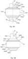
- Figs 15A-B illustrate schematically such conical and hyperbolic top and bottom surfaces.
- the pile arrangement comprises a cylindrical stem 1702 and a base structure 1703.
- the base structure 1703 comprises a number of concentrically arranged cylindrical walls comprising an innermost cylindrical wall 1704', an outermost cylindrical wall 1704" and three intermediate cylindrical walls.
- the radial walls are not shown in figs. 15A-B .
- Each cylindrical wall has a lower first edge 1704a', 1704a" and an upper second edge 1704b', 1704b".
- the lower first edges 1704a', 1704a" of all cylindrical walls, including the intermediate cylindrical walls lie on a common straight line L1 which extends in a longitudinal plane of the pile arrangement.
- the bottom surface is conical in this example.
- the general bottom surface inclination angle Ab is defined as the angle between this line L1 and the longitudinal direction Ld of the pile arrangement. In the example shown in fig 17A the bottom surface inclination angle Ab is approx. 45°.
- all upper second edges 1704b', 1704b", including the intermediate upper second edges are arranged on a common straight line L2 which extends in a longitudinal plane of the pile arrangement.
- the top surface is conical and, in this example, the top surface inclination angle At is approx. 60°.
- Fig 15B illustrates schematically an example where the top and bottom surfaces of the base structure are hyperbolic.
- the pile arrangement comprises a stem 1802 and a base structure 1803 comprising an innermost cylindrical wall 1804', an outermost cylindrical wall 1804" and a number of intermediate cylindrical walls.
- the upper second edges 1804b', 1804b" of all cylindrical walls are not arranged on a straight line but on a concave line Lc, such that the top surface of the base structure 1803 is hyperbolic.
- the general inclination of the top surface is defined as the angle At between the longitudinal direction Ld and a straight line L3 which extends in a longitudinal plane and which connects the upper second edges 1804b', 1804b" of the innermost 1804' and the outermost 1804" cylindrical walls, but not of the intermediate cylindrical walls.
- the top surface inclination angle At is approx. 45°.
- the bottom surface is hyperbolic having a bottom surface inclination angle of approx. 45°
- the pile arrangement 1 shown in figs 1-3C has proven to exhibit an advantageous balance between coring during the vibration driving and plugging of the cells 6 after completion of the vibration driving. This results in excellent drivability in combination with high load capacity when installed.
- Figs 4A-C illustrates a second embodiment of a pile arrangement 101.
- This pile arrangement 101 comprises a stem 102 and a base structure 103 arranged concentrically around the stem 102 at its first end 102a.
- the base structure 103 comprises five concentrically arranged cylindrical walls 104 supported by twelve radial walls.
- the cross-sectional geometry is similar to the one shown in fig 3a and comprises 60 longitudinally open cells 106 exhibiting essentially equal cross-sectional areas.
- the pile arrangement 106 differs from the one shown in figs 1-3C in that the base structure 103 is arranged at the first end 102a of the stem 102. By this means, the pile arrangement 106 does not exhibit any ground spike formed by a downwardly protruding portion of the stem. However, also at this embodiment the vertical height of the cylindrical walls 104 and the radial walls 105 decreases in the radial outward direction. By this means, the lower first edges 104a of the cylindrical walls 104 define a sloping bottom surface of the base structure 103. At this embodiment the lower first edges 104 lie on a concave line connecting the innermost and the outermost lower first edges 104a. By this means the bottom surface defined by the lower first edges 104 exhibits a hyperbolic shape. Correspondingly the upper second edges 104b of the cylindrical walls 104 define a hyperbolic top surface of the base structure 103.
- the hyperbolic top and bottom surfaces of base structure 103 greatly enhances the load capacity of the pile arrangement 101 after installation, especially for vertically directed loads.
- the hyperbolic bottom surface of the base structure 103 which bottom surface is arranged close to the first end 102, further acts as a ground spike during the initial penetration into the ground or seabed.
- the sloping bottom surface results in a gradual increase of the driving resistance experienced by the pile arrangement 101 during the initial penetration into the ground or seabed. This facilitates maintaining the vertical orientation of the pile arrangement during the initial phase of the vibration driving.
- the embodiment of the pile arrangement 201 shown in figs 5A-C comprises a stem 202 and a base structure 203 which is arranged in proximity to the first end 202a of the stem 202.
- the base structure 203 comprises three cylindrical walls 204 concentrically arranged around the 202 and a plurality of radial walls 205.
- the radial distance between the cylindrical walls 204 is equal for the entire base structure 203 and the plurality of radial walls 205 are circumferentially distributed such that all longitudinally open cells 206 defined by the cylindrical 204 and the radial walls 205 exhibit essentially equal cross-sectional area.
- all the cylindrical 204 and the vertical 205 walls exhibit equal longitudinal height such that the base structure 203 exhibits a flat bottom surface and a flat top surface, both surfaces being arranged in the horizontal plane being perpendicular to the longitudinal direction of the stem 202.
- the first end 202a protrudes somewhat beyond the bottom surface of the base structure 203 to thereby form a comparatively short ground spike.
- the pile arrangement 301 comprises a stem 302 and a base structure 303 arranged at the first end 302a of the stem 302.
- the base structure 303 comprises five concentrically arranged cylindrical walls 304 separated by radial distances which decrease outwardly between each pair of adjacent cylindrical walls and twelve radial walls 305.
- the cylindrical 304 and radial 305 walls define longitudinally open cells 306 having equal cross-sectional areas.
- all cylindrical walls 304 are of the same height such that the bottom and top surfaces defined by the cylindrical walls lower first and upper second 304b edges are flat and horizontally oriented.
- the vertical height of the radial walls 305 decreases in the radial outward direction.
- the radial cross-sectional area of the radial walls 305 also decreases in the radial outward direction from the stem 302.
- the pile arrangement 401 comprises a stem 402 and a base structure 403.
- the base structure comprises five concentrically arranged cylindrical walls 404 which are separated by equal radial distances and twelve radial walls 405 which walls 404, 405 together with the stem 402 define 60 longitudinally open cells 406.
- the cross-sectional area of the cells increases in the radial outward direction.
- the cylindrical walls 404 and the radial walls 405 have equal and constant height such that the bottom surface and the top surface defined by the lower first and upper second 404b edges of the cylindrical walls 404 are flat and horizontally arranged.
- the shortest distance between two non-adjacent walls defining each cell is the radial distance between the two cylindrical walls which define the cell.
- the significant distance is thus constituted by the radial distance between the two cylindrical walls defining the cell.
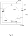
- Figs 8A-G illustrate alternative cross-sectional geometries of the base structure at pile arrangements according to further embodiments.
- the significant distance of some exemplifying cells has been given the reference Sd.
- the pile arrangement shown in fig 8A comprises a cylindrical stem 502 and a baste structure 503 arranged concentrically around the stem 502.
- the base structure comprises five concentrically arranged cylindrical walls 504 and twelve radial walls 505 defining together with the stem 502 60 longitudinally open cells 506.
- the radial distance between the cylindrical walls 504 decreases in the radial outward direction.
- the significant distance Sd1-Sd5 of each cell 506 is constituted by the radial distance between the two cylindrical walls 504 defining the cell 506.
- the circumferential thickness of the radial walls 505 decreases gradually in the radial outward direction. Additionally, the radial thickness of the cylindrical walls 504 decrease wall by wall in the radial outward direction. Such a decrease of the thickness and thereby of the cross-sectional area of the walls 504, 505 is advantageous from a structural impedance and a structural efficiency point of view as discussed above with reference to the nineth aspect.
- the pile arrangement shown in fig 8B comprises a cylindrical stem 602 and a base structure 603 arranged concentrically around the stem 602.
- the base structure 603 comprises three concentrically arranged cylindrical walls 604 separated by equal radial distance.
- the radial thickness of the cylindrical walls 604 decrease wall by wall in the radial outward direction.
- the base structure 603 further comprises a plurality of radial walls 605.
- the circumferential thickness of each radial wall 605 decreases in the radial outward direction.
- the cylindrical walls 604 and the radial walls 605 define, together with the stem 602, a plurality of longitudinally open cells 606.
- each cell 606 is here constituted by the circumferential distance between the two radial walls 605 defining the cell 506.
- the cross-sectional area of the cells 606 varies less than 10% between all cells 606 in the base structure 603.
- the pile arrangement shown in fig 8C comprises a cylindrical stem 702 and a base structure 703, the cross-section of which generally forms a hexagon which is symmetrically arranged around the stem 702.
- the base structure 703 comprises a plurality of longitudinally open cells 706 which are symmetrically distributed around the stem 702.
- Each cell 706 is defined by six walls having equal length in the cross-sectional plane such that each cell 706 exhibits an equilateral hexagonal cross-section.
- the cross-sectional area is equal for all cells 706 and the significant distances Sd of each cell 706 is the shortest distance between two non-adjacent walls, which in this case is equal to the length of the sides of the cells' hexagonal cross-section.
- the pile arrangement schematically shown in fig 8D comprises a tubular stem 802 having a square cross-section and a base structure 803.
- the base structure comprises two tubular walls 804 having square cross-sections which tubular walls 804 are concentrically arranged around the stem 802.
- the tubular walls 804 are connected by means of laterally extending partition walls 805.
- the tubular walls 804 and the partition walls 805 define together with the tubular stem 802 a plurality of longitudinally open cells 806a, 806b.
- some of the cells 806a have generally L-shaped cross-sections whereas other cells 806b have rectangular cross-section.
- each cell 806a, 806b is constituted by the shortest distance between the two tubular walls 805 or between the stem 802 and the innermost tubular wall 805 which distance in this case is equal to the length in the cross-sectional plane of the partition walls 805.
- the pile arrangement schematically illustrated in fig 8E comprises a tubular stem 902 having a cross-section forming an equilateral triangle and a base structure 903.
- the base structure comprises one tubular wall 904 having a cross-section forming a equilateral triangle which is concentrically arranged outside the tubular stem 902.
- the base structure also comprises a plurality of partition walls 905 which are arranged such that they, together with the tubular wall 904 and the stem 802 from a plurality of longitudinally open cells 906.
- Each cell 806 exhibits a cross-section having the form of an equilateral triangle.
- the significant distance is constituted by the shortest one of the base and the height in the cells 806 triangular cross-section. Since the cross-section of the cells 906 at this embodiment is equilateral, the significant distance Sd is constituted by the cross-sectional triangle's height.
- the pile arrangement schematically illustrated in fig 8F comprises a tubular stem 1002 having octagonal cross-section and a base structure 1003.
- the base structure 1003 comprises two tubular walls 1004, which have octagonal cross-sections and which are arranged concentrically around the stem 1002.
- the base structure 1003 further comprise a plurality of radial walls 1005 which extends from the stem 1002 to the outermost tubular wall 1004.
- the tubular walls 1004 and the radial walls 1005 define together with the stem 1002 a plurality of longitudinally open cells 1006 having angled cross-sections.
- the significant distance Sd is equal for all cells 1006 and is constituted by the radial distance between the stem 1002 and the inner tubular wall and the radial distance between the inner and the outer tubular walls respectively.
- the pile arrangement schematically illustrated in fig 8G comprises a cylindrical stem 1102 and a base structure 1103.
- the base structure 1103 comprises an inner tubular wall 1104a and an outer tubular wall 1104b. Both tubular walls 1104a, 1104b have square cross-sections and are concentrically arranged around the stem 1102.
- the base structure further comprises a plurality of partition walls 1105 which all have equal length in the cross-sectional plane.
- the inner tubular wall 1104a is connected to the stem by means of four inner partition walls 1105a evenly distributed around the stem 1102. By this means, the inner tubular wall 1104a and the inner partition walls 1105a define together with the stem 1102 four inner longitudinally open cells 1106a.
- the inner tubular wall 1104a and the outer tubular wall 1104b define together with the outer partition walls 1105b a plurality of outer longitudinally open cells 1106b some of which have rectangular cross-section and some angled cross-section.
- the significant distance Sdi, Sd2 for each of the inner 1106a and outer 1106b cells is constituted by the length of the inner 1105a and outer 1105b partition walls respectively. Since the inner 1105a and outer 1105b partition walls have equal length in the cross-sectional plane the significant distance Sdi, Sd2 is equal for all cells 1106a, 1106b.
- FIGs 9A and 9B schematically illustrate a respective pile arrangement 1301, 1401 in accordance with the twelfth aspect discussed above. Both figures 9A and 9B show the respective pile arrangement 1301, 1401, after installation into a seabed, in a side view and in a cross-sectional view from line A-A.
- Both pile arrangements comprise a cylindrical stem 1302, 1402 and a base structure 1303, 1403 concentrically arranged around the stem 1302, 1402 in proximity to the first end 1302a, 1402a of the stem 1302, 1402.
- the stem 1302, 1402 and the base structure 1303, 1402 are essentially identical to the stem 2 and base structure 3 shown in figs 1-3C and are not further described here.
- the pile arrangements 1301, 1401 differ from the previously described pile arrangements in that they each comprise a top structure 1310, 1410 arranged in proximity to the upper second end 1302b, 1402b of the stem 1302, 1402.
- the top structure 1310 comprises four fins 1311a-d which are fixed to an upper portion of the stem 1302, i.e. in proximity to the upper second end 1302b of the stem 1302.
- Each fin 1311a-c comprises a rectangular steel plate which is arranged such that it extends in parallel with the longitudinal direction of the stem 1302 and protrudes radially from the stem 1302.
- the fins 1311a-c are further symmetrically distributed around the periphery of the stem 1302.
- the pile arrangement 1301 is vibration driven to an embedment depth at which the fins 1311a-d are at least partly embedded into the seabed.
- the fins will transmit horizontal loads to the surrounding soil whereby the horizontal load capacity of the pile arrangement 1301 is enhanced considerably, as discussed further in detail in the Summary above with reference to the twelfth aspect.
- the top structure 1410 also comprises four fins 1411a-d which are shaped and arranged essentially as the fins 1311a-d shown in fig 9a .
- the top structure 1410 further comprises a cylindrical wall 1412 which is arranged concentrically around the stem 14012 and fixed to the radially outer edges of the fins 1411a-d.
- the fins 1411a-c and the cylindrical wall 1412 define together with the stem 1402 four longitudinally open cells 1413a-d.
- the top structure 1401 may preferably be designed such that the open cells 1413a-d during vibration driving of the pile arrangement 1401 promotes coring and after installation promotes plugging of the cells 1413a-d. Also the advantages of the top structure 1410 shown in fig 9b are further discussed in the above summary with reference to the twelfth aspect.
- Figs 13A to 14 illustrate schematically pile arrangements according to the sixteenth aspect.
- the pile arrangement comprises a base structure 1503, 1603 with longitudinally open cells as described above.
- the pile arrangement comprises a plurality of stems 1502a-c, 1602 a-c.
- Each stem extends, just as in the previous embodiments, between a first end which is intended to be positioned below a second end when installed.
- the base structure 1503, 1603 is arranged at the first ends of the stems 1502a-c, 1602a-c.
- the second ends of the stems 1502a-c are not interconnected and form independent anchoring points to which mooring lines or the like may be fixed when the pile arrangement has been installed.
- the second, upper ends of the stems 1602a-c are mutually connected such as to form a single anchoring structure of the pile arrangement.
- the second ends of the stems 1602a-c are interconnected by means of a cylindrical sleeve 1616 arranged between the second upper ends of the stems 1602a-c such that the second ends are fixed to the outer periphery of the cylindrical sleeve 1616.
- the stem and/or the base structure of the pile arrangements according to the various embodiments described above may preferably be manufactured in a structurally rigid material such as e.g. steel or fibre reinforced composite material or other materials exhibiting sufficient strength and fatigue for the loads experienced during installation and operation.
- the base structure and/or the stem may be manufactured by rolling sheet metal and welding the longitudinal edges of said sheets together to form a straight hollow pipe or cylinder.
- Such hollow pipes or cylinders may be used for forming the cylindrical walls of the base structure.
- several so formed hollow pipes may be joined together longitudinally e.g. by butt welding to form longitudinal sections of the finished stem.
- Another method of forming, especially the stem is by spiral-welding of elongate rectangular sheets of metal which sheets are spirally rolled and spirally welded along their longitudinal edges.
- the base structure and/or the stem may be manufactured of fibre-reinforced plastic using a filament winding process or other automated additive manufacturing processes for fibre-reinforced pipe sections.
- the walls of the pipe section may be built up layer by layer by mixing fibre and resin/prepeg to form a composite matrix with multiple fibre directions combined in a stack of layers to form a pipe section that can resist vertical tension and compression loading as well as bending and twisting loads using a minimum amount of layers and wall thickness.
- the base structure may also be formed by bending segments of sheet metal and welding the segments into the open cell arrangement of the base structure.
- a base structure may be formed by welding the radial segments onto a stem, followed by adding concentric ring segments to it by bending sheets into circle segments that are welded or otherwise rigidly jointed to the radial segments to form rings.
- Each segment may also be generally L-shaped in the cross-sectional plane of the base structure. One leg of the L-shaped segment may be straight to form a radial wall of a cell and the other leg may be curved to form a circle segment forming the outer circular wall segment of the same cell.
- a plurality of such L-shaped segment may thereafter be welded circumferentially onto the periphery of the stem such as to form the radial innermost ring of cells where the curved legs of the segments together form the innermost circular wall of the base structure.
- the base structure may be completed to comprise any desired number of concentrically arranged circular walls radially separated by the straight legs of the L-shaped segments.
- the base structure may also be manufactured by first forming a number of sheet metal cylinders having different diameters and a number of straight rectangular sheet metal walls. Thereafter slits which extend in the longitudinal direction of the finished base structure may be cut out in the cylindrical and the straight walls. Preferably the slits may extend approximately over half the vertical height and be cut from opposing edges in the cylindrical and straight walls respectively.
- the base structure is thereafter formed by arranging the cylindrical walls concentrically around the stem and the straight walls radially out from the stem while having the cylindrical walls to be received in the slits of the radial walls and vice versa where these walls intersect. Finally, the intersections may be secured by welding.
- the base structure may be attached to the stem by welding at least one radial wall of the base structure onto the outer wall surface of the stem, either as part of the process where the base structure is fabricated, or afterwards joining a finished base structure to the stem.
- the base structure may be formed by 3D printing, casting and/or infusion of resin in a mold carrying a fibre material.
- a portion of the stem residing within the height of the base structure may be casted in the same process, and the pile arrangement may then be formed by joining such base structure having a stem-portion with a second piece of stem to form the overall stem.
- the pile arrangement comprises a stem extending 2 in a longitudinal direction between a first end 2a and a second end 2b, and a base structure 3 arranged at or in proximity to the first end 2a, which base structure 3 comprises a plurality of longitudinally open cells 6 (see fig 2a-c ), which cells are symmetrically arranged around the stem 2 in the cross section of the base structure 3, each cell being defined by a plurality of cell walls 4, 5 extending in the longitudinal direction.
- the method comprises the steps;
- the pile arrangement after installation is oriented such that the longitudinal direction of the stem deviates from the vertical direction.
- An example of such an application is when the pile arrangement is used as a subsea anchorage for a floating structure such as a wave energy converter buoy.
- the load to be sustained by the pile arrangement is typically applied to the upper second end of the stem as non-vertical pulling force transmitted to the stem by a mooring wire.
- the stem In order to increase the capacity of the pile arrangement to sustain such non-vertical loads it may be advantageous to orient the stem such that it is generally aligned with the direction in which the mooring wire extends when transmitting the force to pile arrangement.
- Figs 10A - 12 schematically illustrate three different methods for accomplishing such reorientation of the pile arrangement.
- the exemplifying pile arrangements 1 used in these methods is essentially identical to the pile arrangement 1 shown in figs 1 - 3c and is not described in detail again here.
- the pile arrangement 1 is initially vibration driven in the vertical direction, by means of the oscillating device 23, to a predetermined embedment depth.
- This initial driving may be accomplished by the method described above with reference to fig 1 .
- the pile arrangement 1 has reached the position and vertical orientation shown in fig 10A .
- a wire 26 is fixed to the oscillation device 23 and to a vessel 27.
- the reorientation of the pile arrangement 1 is thereafter accomplished by maintaining the oscillation device 23 active to thereby continuously vibrate the pile arrangement at a predetermined frequency during the reorientation phase.
- the actual reorientation is accomplished by driving the vessel 27 horizontally away from the pile arrangement such that a non-vertical pulling force is transmitted to the top of the pile arrangement 1 via the wire 26.
- the pile arrangement will pivot about a horizontal pivotal axis extending through the stem 2, such that the pile arrangement assumes the non-vertical orientation illustrated in fig 10b .
- the oscillation device 23 is detached from the pile arrangement 1.
- the continuous vibration of the pile arrangement 1 during the reorientation phase reduces the friction between the pile arrangement and the surrounding soil such that the pulling force applied by the vessel via the wire may be importantly reduced, in comparison to a corresponding reorientation operation without simultaneous vibration of the pile arrangement.
- the above-described reorientation method may advantageously be applied to pile arrangements at which the stem and the base structure have comparatively large diameters.
- the pile arrangement has also been initially vibration driven vertically to a predetermined embedment depth illustrated in fig 11A . Thereafter the oscillating device has been detached and the vessel has been connected to the second end 2a of the pile arrangement's 1 stem 2 via the wire 26.
- the reorientation operation is carried out in a similar manner as described above, by driving the vessel 27 away from the pile arrangement 1 such that a non-vertical pulling force is applied to the second end 2b of stem 2.
- the pile arrangement is pivoted about a horizontal pivotal axis extending through the stem until the pile arrangement reaches the orientation shown in fig 11B .
- the reorientation method illustrated in figs 11A-B differs from the one illustrated in figs 10A-B in that no vibration is applied to the pile arrangement during the reorientation phase.
- This non-vibrational reorientation method exhibits the advantage of not requiring any handling of an oscillation device during the reorientation.
- This later reorientation method may advantageously be used for slender pile arrangements where the diameters of the stem and the base structure are comparatively small.
- Fig 12 illustrates schematically a method of driving a pile arrangement 1 into a seabed at non vertical direction.
- the exemplifying pile arrangement 1 is essentially identical to the pile arrangement 1 shown in figs 1 - 3C and is not described in detail again here.
- this method makes use of a pile guiding device 30 comprising a base 31 and a guiding structure 32 which is pivotal relative to the base 31 and which is arranged to support the stem 2 of the pile arrangement 1 to be driven.
- the non-vertical driving angle may be set to any desired value.
- the method is carried out by first positioning the pile guiding device at the desired position on the seabed or ground and adjusting the pivotal angle such that the guiding structure assumes the desired installation angel. Thereafter or before the pile arrangement 1 is positioned on the pile guiding device 30 such that the stem 2 is supported by the guiding structure 32. Then, an oscillating device 23 attached to the second end 2b of the stem is activated to vibrate the pile arrangement at a predetermined frequency. While maintaining the vibration active the pile arrangement is allowed to slide along the guide structure 32 into the ground or seabed. At some applications such sliding may be accomplished merely by the influence of the gravity acting on the pile arrangement 1 and the oscillation device 23.
- the above-described method is advantageous e.g. in that it allows for that the installation angle may be controlled with high accuracy.
- the method described above with reference to fig 12 is further discussed in the above summary with reference to the sixteenth aspect.
Landscapes
- Engineering & Computer Science (AREA)
- Structural Engineering (AREA)
- General Engineering & Computer Science (AREA)
- Life Sciences & Earth Sciences (AREA)
- General Life Sciences & Earth Sciences (AREA)
- Mining & Mineral Resources (AREA)
- Paleontology (AREA)
- Civil Engineering (AREA)
- Piles And Underground Anchors (AREA)
Priority Applications (4)
| Application Number | Priority Date | Filing Date | Title |
|---|---|---|---|
| EP22151604.0A EP4212672A1 (fr) | 2022-01-14 | 2022-01-14 | Agencement formant pieu et procédé d'installation par vibration |
| AU2023207810A AU2023207810A1 (en) | 2022-01-14 | 2023-01-16 | Pile arrangement for and method of vibration driving |
| PCT/EP2023/050827 WO2023135282A1 (fr) | 2022-01-14 | 2023-01-16 | Agencement de pieu et procédé d'entraînement par vibration |
| CN202380016929.0A CN118556148A (zh) | 2022-01-14 | 2023-01-16 | 用于振动驱打的桩装置和方法 |
Applications Claiming Priority (1)
| Application Number | Priority Date | Filing Date | Title |
|---|---|---|---|
| EP22151604.0A EP4212672A1 (fr) | 2022-01-14 | 2022-01-14 | Agencement formant pieu et procédé d'installation par vibration |
Publications (1)
| Publication Number | Publication Date |
|---|---|
| EP4212672A1 true EP4212672A1 (fr) | 2023-07-19 |
Family
ID=80112447
Family Applications (1)
| Application Number | Title | Priority Date | Filing Date |
|---|---|---|---|
| EP22151604.0A Pending EP4212672A1 (fr) | 2022-01-14 | 2022-01-14 | Agencement formant pieu et procédé d'installation par vibration |
Country Status (4)
| Country | Link |
|---|---|
| EP (1) | EP4212672A1 (fr) |
| CN (1) | CN118556148A (fr) |
| AU (1) | AU2023207810A1 (fr) |
| WO (1) | WO2023135282A1 (fr) |
Citations (7)
| Publication number | Priority date | Publication date | Assignee | Title |
|---|---|---|---|---|
| US3683633A (en) * | 1969-07-10 | 1972-08-15 | Tot Aanneming Van Werken Voorh | Metal foundation pile |
| WO1995035416A1 (fr) * | 1994-06-17 | 1995-12-28 | Geo Engineering Ab | Structure permettant d'accroitre la force portante d'un pieu |
| JP2000110185A (ja) * | 1998-10-06 | 2000-04-18 | Ohbayashi Corp | 水中基礎の構築工法 |
| JP2013256791A (ja) * | 2012-06-12 | 2013-12-26 | Nippon Steel & Sumitomo Metal | 管杭及びその施工方法 |
| EP3124706A1 (fr) * | 2015-07-28 | 2017-02-01 | Swietelsky Baugesellschaft m.b.H. | Dispositif de mesure d'inclinaison pour un pilon vibrant |
| DE102019104292A1 (de) * | 2019-02-20 | 2020-08-20 | Innogy Se | Einvibrieren von Gründungen |
| WO2021045626A1 (fr) * | 2019-06-03 | 2021-03-11 | Dr. Techn. Olav Olsen As | Dispositif d'ancrage de sol faible servant à ancrer au moins une structure et procédé d'agencement d'ancrage dans un sol faible |
-
2022
- 2022-01-14 EP EP22151604.0A patent/EP4212672A1/fr active Pending
-
2023
- 2023-01-16 CN CN202380016929.0A patent/CN118556148A/zh active Pending
- 2023-01-16 AU AU2023207810A patent/AU2023207810A1/en active Pending
- 2023-01-16 WO PCT/EP2023/050827 patent/WO2023135282A1/fr active Application Filing
Patent Citations (7)
| Publication number | Priority date | Publication date | Assignee | Title |
|---|---|---|---|---|
| US3683633A (en) * | 1969-07-10 | 1972-08-15 | Tot Aanneming Van Werken Voorh | Metal foundation pile |
| WO1995035416A1 (fr) * | 1994-06-17 | 1995-12-28 | Geo Engineering Ab | Structure permettant d'accroitre la force portante d'un pieu |
| JP2000110185A (ja) * | 1998-10-06 | 2000-04-18 | Ohbayashi Corp | 水中基礎の構築工法 |
| JP2013256791A (ja) * | 2012-06-12 | 2013-12-26 | Nippon Steel & Sumitomo Metal | 管杭及びその施工方法 |
| EP3124706A1 (fr) * | 2015-07-28 | 2017-02-01 | Swietelsky Baugesellschaft m.b.H. | Dispositif de mesure d'inclinaison pour un pilon vibrant |
| DE102019104292A1 (de) * | 2019-02-20 | 2020-08-20 | Innogy Se | Einvibrieren von Gründungen |
| WO2021045626A1 (fr) * | 2019-06-03 | 2021-03-11 | Dr. Techn. Olav Olsen As | Dispositif d'ancrage de sol faible servant à ancrer au moins une structure et procédé d'agencement d'ancrage dans un sol faible |
Also Published As
| Publication number | Publication date |
|---|---|
| WO2023135282A1 (fr) | 2023-07-20 |
| AU2023207810A1 (en) | 2024-08-29 |
| CN118556148A (zh) | 2024-08-27 |
Similar Documents
| Publication | Publication Date | Title |
|---|---|---|
| CA2475354C (fr) | Aerogenerateur | |
| CN101495701A (zh) | 扭矩下降桩底层结构支承系统 | |
| US20220195686A1 (en) | Anchoring Element | |
| KR101573064B1 (ko) | 해상 녹색에너지 발전을 포함하는 기초 파일 시공용 지그 및 이를 이용한 해상 기초구조물 시공 공법 | |
| EP2828435A1 (fr) | Structures pour installations offshore | |
| US20130101359A1 (en) | Anchoring element for a hydraulic engineering installation | |
| JP5820678B2 (ja) | 海洋構造物およびその設置構造 | |
| EP4212672A1 (fr) | Agencement formant pieu et procédé d'installation par vibration | |
| US5505561A (en) | Self-piloting compressible piling | |
| KR101043605B1 (ko) | 해상 구조물의 설치를 위한 연약지반용 단일 지지 파일의 멀티형 서포트 커넥터 기구 | |
| KR20240132076A (ko) | 진동 구동을 위한 파일 장치 및 방법 | |
| US20220298739A1 (en) | Weak soil anchor device to anchor one or several structures and method to arrange an anchor in weak soil | |
| RU83780U1 (ru) | Свая забивная и устройство для ее погружения | |
| CN211336346U (zh) | 一种基于鱼雷锚贯入的多桩式锚泊基础 | |
| CN210368954U (zh) | 一种锚杆或桩基用简明网格结构的变直径钢筋笼 | |
| TW202134502A (zh) | 風電場基座結構及用於製造風電場基座結構之方法 | |
| EP3385451B1 (fr) | Structure de support destinée à une éolienne offshore | |
| CN209523191U (zh) | 一种用于混凝土桩体的辅助打桩装置 | |
| CN210104785U (zh) | 具有破冰结构的重力式海上风机基础 | |
| CN220117199U (zh) | 一种海上钢管桩抱箍安装装置 | |
| CN211690267U (zh) | 一种基于鱼雷锚贯入的桩锚式锚泊基础 | |
| CN214733753U (zh) | 一种钢沉井倾斜接高起吊装置 | |
| CN114086595B (zh) | 一种塔吊基础及其稳固工艺 | |
| CN220868200U (zh) | 一种带限位装置钢筋笼及锚杆 | |
| EP2558647B1 (fr) | Structure de fondation en mer, fondation en mer utilisant une telle structure et procédé d'installation d'une fondation en mer |
Legal Events
| Date | Code | Title | Description |
|---|---|---|---|
| PUAI | Public reference made under article 153(3) epc to a published international application that has entered the european phase |
Free format text: ORIGINAL CODE: 0009012 |
|
| STAA | Information on the status of an ep patent application or granted ep patent |
Free format text: STATUS: THE APPLICATION HAS BEEN PUBLISHED |
|
| AK | Designated contracting states |
Kind code of ref document: A1 Designated state(s): AL AT BE BG CH CY CZ DE DK EE ES FI FR GB GR HR HU IE IS IT LI LT LU LV MC MK MT NL NO PL PT RO RS SE SI SK SM TR |
|
| STAA | Information on the status of an ep patent application or granted ep patent |
Free format text: STATUS: REQUEST FOR EXAMINATION WAS MADE |
|
| 17P | Request for examination filed |
Effective date: 20230816 |
|
| RBV | Designated contracting states (corrected) |
Designated state(s): AL AT BE BG CH CY CZ DE DK EE ES FI FR GB GR HR HU IE IS IT LI LT LU LV MC MK MT NL NO PL PT RO RS SE SI SK SM TR |
|
| STAA | Information on the status of an ep patent application or granted ep patent |
Free format text: STATUS: EXAMINATION IS IN PROGRESS |
|
| 17Q | First examination report despatched |
Effective date: 20240102 |