EP4211050B1 - Kabelbinder - Google Patents
Kabelbinder Download PDFInfo
- Publication number
- EP4211050B1 EP4211050B1 EP22785069.0A EP22785069A EP4211050B1 EP 4211050 B1 EP4211050 B1 EP 4211050B1 EP 22785069 A EP22785069 A EP 22785069A EP 4211050 B1 EP4211050 B1 EP 4211050B1
- Authority
- EP
- European Patent Office
- Prior art keywords
- cord
- cable tie
- metal blade
- passage
- diameter
- Prior art date
- Legal status (The legal status is an assumption and is not a legal conclusion. Google has not performed a legal analysis and makes no representation as to the accuracy of the status listed.)
- Active
Links
Images

Classifications
-
- B—PERFORMING OPERATIONS; TRANSPORTING
- B65—CONVEYING; PACKING; STORING; HANDLING THIN OR FILAMENTARY MATERIAL
- B65D—CONTAINERS FOR STORAGE OR TRANSPORT OF ARTICLES OR MATERIALS, e.g. BAGS, BARRELS, BOTTLES, BOXES, CANS, CARTONS, CRATES, DRUMS, JARS, TANKS, HOPPERS, FORWARDING CONTAINERS; ACCESSORIES, CLOSURES, OR FITTINGS THEREFOR; PACKAGING ELEMENTS; PACKAGES
- B65D63/00—Flexible elongated elements, e.g. straps, for bundling or supporting articles
- B65D63/10—Non-metallic straps, tapes, or bands; Filamentary elements, e.g. strings, threads or wires; Joints between ends thereof
- B65D63/1018—Joints produced by application of integral securing members, e.g. buckles, wedges, tongue and slot, locking head and teeth or the like
- B65D63/1027—Joints produced by application of integral securing members, e.g. buckles, wedges, tongue and slot, locking head and teeth or the like the integral securing member being formed as a female and male locking member, e.g. locking head and locking teeth, or the like
- B65D63/1036—Joints produced by application of integral securing members, e.g. buckles, wedges, tongue and slot, locking head and teeth or the like the integral securing member being formed as a female and male locking member, e.g. locking head and locking teeth, or the like the female locking member being provided with at least one metal barb
-
- F—MECHANICAL ENGINEERING; LIGHTING; HEATING; WEAPONS; BLASTING
- F16—ENGINEERING ELEMENTS AND UNITS; GENERAL MEASURES FOR PRODUCING AND MAINTAINING EFFECTIVE FUNCTIONING OF MACHINES OR INSTALLATIONS; THERMAL INSULATION IN GENERAL
- F16L—PIPES; JOINTS OR FITTINGS FOR PIPES; SUPPORTS FOR PIPES, CABLES OR PROTECTIVE TUBING; MEANS FOR THERMAL INSULATION IN GENERAL
- F16L3/00—Supports for pipes, cables or protective tubing, e.g. hangers, holders, clamps, cleats, clips, brackets
- F16L3/22—Supports for pipes, cables or protective tubing, e.g. hangers, holders, clamps, cleats, clips, brackets specially adapted for supporting a number of parallel pipes at intervals
- F16L3/23—Supports for pipes, cables or protective tubing, e.g. hangers, holders, clamps, cleats, clips, brackets specially adapted for supporting a number of parallel pipes at intervals for a bundle of pipes or a plurality of pipes placed side by side in contact with each other
- F16L3/233—Supports for pipes, cables or protective tubing, e.g. hangers, holders, clamps, cleats, clips, brackets specially adapted for supporting a number of parallel pipes at intervals for a bundle of pipes or a plurality of pipes placed side by side in contact with each other by means of a flexible band
- F16L3/2338—Supports for pipes, cables or protective tubing, e.g. hangers, holders, clamps, cleats, clips, brackets specially adapted for supporting a number of parallel pipes at intervals for a bundle of pipes or a plurality of pipes placed side by side in contact with each other by means of a flexible band having at least one metal locking barb
Definitions
- the present disclosure relates to the field of cable ties, in particular environmentally friendly and tamper evident cable ties.
- Cable ties also referred to as zip ties or plastic straps have long been used to secure cables and other articles together.
- Cable ties are used in large quantities and many of them eventually end up in the environment after use and present a danger for animals that can get entangled or swallow them. Further, the commercially available cable ties are typically formed from plastic materials having large carbon footprint.
- US20020170152A1 discloses a low profile cable tie, preferably a two-piece cable tie, having a low profile locking head with a lateral strap accepting channel and a strap preferably molded with a right angle bend that is retained in this state during non-use.
- a strap accepting channel is provided in the locking head that is substantially parallel to a strap attachment axis.
- the strap accepting channel divides the locking head into a first part, which is secured to the strap, and a second part which contains a locking device. By providing the locking device on the second part, the first part can be made thinner, allowing the strap accepting channel to be closer to the cable bundle being tied.
- the locking device is preferably bent so as to have a fixed end substantially parallel to the strap accepting channel axis and a free end positioned within the strap accepting channel at an acute angle relative to the strap accepting channel axis.
- a bottom wall may be shorter in length than an upper wall to define a recessed inset that widens the effective strap accepting channel entrance without increasing the height of the locking head. The inset also allows entrance of the strap over a broader range of entrance angles.
- GB2530773A discloses a fastener comprising a single sheet of flexible paper or card 1 having an elongate portion with teeth projecting from at least one side of part of its length; and an aperture through part of the fastener at least as narrow as the widest part of the elongate portion measured across the teeth but at least as wide as the narrowest part of the elongate portion.
- the teeth can be angled with opposed faces inclined at different angles so that it is easier to insert them through the aperture than withdraw them.
- the aperture could be formed in an enlarged head at one end of the fastener.
- the teeth can be directly adjacent, either with a triangular gap separating them or being separated by only a cut.
- the material forming the fastener is 200-900g/m2 paperboard with elasticity of 15% along its length and 10% across its width.
- the fastener could pass through two holes in packaging material to secure a toy to it.
- the cable lacing tie devices include a head assembly and a cable lacing tape.
- the head assembly being configured to retain a first portion of the cable lacing tape within the head assembly and having a length of the cable lacing tape extending from the head assembly.
- the head assembly further adapted to retain a second portion of the cable lacing tape extending from the head assembly.
- the methods of using the cable lacing tie devices to hold together a plurality of objects with a cable lacing tie device include retaining a first portion of a cable lacing tape in a head assembly, looping the cable lacing tape around the plurality of objects and retaining a second portion of the cable lacing tape within the head assembly.
- An objective of the present disclosure is to provide a cable tie of reduced environmental impact. Another objective to is provide a cable tie that is strong, non-releasable and tamper evident.
- the present inventors decided to use a cord of cellulosic fibers, such as a cord formed by twisting a paper strip along its length.
- a cord of cellulosic fibers such as a cord formed by twisting a paper strip along its length.
- the present inventors then experimented with different locking head designs. In this work, various designs of a locking head and a locking tooth (or looking teeth) molded in one piece in a plastic material were tested. However, none of these could provide a sufficiently strong and permanent tie. When pulled at a higher force, the cord slipped back through the locking head (i.e. the plastic tooth or teeth failed to prevent untying).
- a cable tie comprising:
- the inlet of the passage may be funnel-shaped, such as trumpet-shaped.
- the second end may be flattened.
- Such a flattened second end may be provided with grooves. Such grooves improve the grip when pulling the cord through the passage.
- the direction of the extension of the grooves is preferably substantially perpendicular to the longitudinal direction of the cord.
- the thickness of the flattened second end may for example be 0.7-1.3 mm, such as 0.9-1.0 mm.
- the width of the flattened second end may for example be 2.7-3.2 mm.
- the thickness to width ratio of the flattened second end is preferably between 1:2.7 and 1:3.5.
- the passage has a central axis and the angle between the direction of the extension of the blade and the central axis is 47°-62°, such as 50°-59°, such as 52°-57. Such an angle has been found to facilitate a strong tie and still allow insertion of the second end into the passage.
- the metal blade intersects the central axis of the passage.
- the metal of the metal blade is steel, preferably stainless steel, such as austenitic stainless steel.
- stainless steel such as austenitic stainless steel.
- a suitable example of an austenitic stainless steel is EN 1.4310.
- the metal blade typically has an embedded portion and an extending portion.
- the blade may be embedded in a body portion of the locking head.
- the body portion preferably comprises a plastic material.
- the length of the extending portion is preferably 20%-40% of the total length of the metal blade, such as 21%-35% of the total length of the metal blade.
- the total length of the metal blade may be 3.5-7.0 mm, such as 4.5-6.0 mm.
- the length of the extending portion may be 55%-90% of the diameter of the cord, such as 70%-90% of the diameter of the cord.
- the width of the metal blade is preferably 60%-80%, such as 67%-73%, such as 73%-77% of the diameter of the cord and/or the thickness of the metal blade is preferably 7-20%, such as 10-15% of the diameter of the cord.
- the diameter of the cord is preferably 26%-49%, such as 31%-46%, such as 36-42%, of the total length of the metal blade. In absolute terms, the diameter of the cord maybe 1.0-8.0 mm, such as 1.8-6.0 mm.
- the cord is formed from hemp or paper, such as waxed paper.
- hemp or paper such as waxed paper.
- the tensile strength of the cord may be 4-80 kg, such as 15-70 kg, measured according to ISO 2062:1993.
- the stretch at break of the cord is 2.5%-6.0%, such as 2.5%-5.0%, when measured according to ISO 2062:1993.
- the above-mentioned body portion is preferably of a biodegradable material, such as a bio composite of a biodegradable and/or renewable polymer and an organic fiber material.
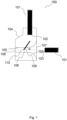
- the cable tie 100 comprises a cord 101 having a first 102 and a second 103 end.
- the cord 101 comprises cellulosic fibers, e.g. in the form of a paper.
- the cord is formed by twisting a paper strip along its length.
- the paper and the forming technique are preferably selected such that high tensile strength and a certain stretchability is obtained (e.g. a stretch at break value of 2%-5%).
- a typical diameter d of the cord 101 may be 2 mm.
- a cord of such a diameter formed by a twisted paper strip may have a tensile strength (ISO 2062:1993) above 20 kg.
- the paper used for the cord is waxed, which facilitates flattening of the second end.
- the tool used for such a pressing operation may have (a) contact surface(s) provided with ridges to form the above-mentioned grooves in the flattened second end.
- the cable ties 100 further comprises a locking head 104 fixedly attached to the first end 102 of the cord 101.
- the fixation is preferably achieved by over-molding the first end 102 with a thermoplastic material that forms a body portion of the locking head 104.
- the locking head 104 is adapted to receive the second end 103 and retain the cable tie 100 in a closed loop configuration.
- the locking head 104 defines a wall 105 that encircles a passage 106.
- the locking head defines a plurality of walls that jointly encircles a passage 106. In either case, the wall(s) prevent(s) substantial lateral movement of the cord 101 when received in the passage 106.
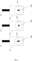
- the passage 106 has an inlet 107 and an outlet 108.
- the inlet 107 is preferably funnel-shaped, such as trumpet-shaped, to facilitate manual insertion of the second end 103 into the passage 106.
- Different passage geometries and trumpet-shaped inlets 107a-c are shown in figure 3 .
- the second end 103 may be flattened.
- the locking head 104 further comprises a metal blade 109 that extends into the passage 106 for engaging the cord 101 after receival thereof.
- the arrangement of the metal blade 109 is such that displacement of the received cord 101 in a first direction towards the outlet 108 is allowed (meaning that the loop formed when the second end 103 is received can be tightened) while displacement of the cord 101 in the opposite direction, i.e. a second direction towards the inlet 107, is prevented (meaning that the tie cannot be released without excessive force or destruction).
- the angle ⁇ between the direction of the extension of the blade 109 and a central axis 110 of the passage 106 is preferably 47°-62°, more preferably 50°-59°, most preferably 52°-57°.
- the metal blade 109 preferably extends to such an extent that it intersects the central axis 110.
- metal blade 109 from stainless steel, e.g. EN 1.4310.
- the metal blade 109 typically has a first portion 109a that is embedded in the body portion of the locking head 104 and a second portion 109b that extends into the passage 106.
- the length of the extending portion 109b is preferably 55%-90%, such as 70%-90%, of the diameter d of the cord 101 and 20%-40%, such as 21%-35%, of the total length of the metal blade 109.
- the length of the extending portion 109b maybe 1.10 - 1.79 mm when the total length of the metal blade 109 is 5.1 mm and the diameter d of the cord 101 is 2 mm.
- the second portion 109b typically become embedded by over-molding with the thermoplastic material that forms the body portion of the locking head 104.
- the first end 102 of the cord 101 and the second portion 109b of the metal blade 109 may, during production, become embedded in the same over-molding step.
- the diameter d of the cord 101 may be 26%-49%, preferably 31%-46%, more preferably 36-42%, of the total length of the metal blade 109.
- the width of the metal blade 109 is typically 60%-80% (preferably 67%-73%, more preferably 73%-77%) of the diameter d of the cord 101. Further, the thickness of the metal blade 109 is typically 7-20% (preferably 10-15%) of the diameter d of the cord 101.
Landscapes
- Engineering & Computer Science (AREA)
- Mechanical Engineering (AREA)
- General Engineering & Computer Science (AREA)
- Package Frames And Binding Bands (AREA)
- Ropes Or Cables (AREA)
- Surgical Instruments (AREA)
- Superconductors And Manufacturing Methods Therefor (AREA)
- Insulated Conductors (AREA)
- Harvester Elements (AREA)
- Flexible Shafts (AREA)
Claims (15)
- Kabelbinder (100), umfassend:- ein Band (101) mit einem ersten Ende (102) und einem zweiten Ende (103), wobei das Band Zellulosefasern umfasst; und- einen Verriegelungskopf (104), der fest an dem ersten Ende (102) angebracht ist, wobei der Verriegelungskopf (104) geeignet ist, das zweite Ende (103) aufzunehmen und den Kabelbinder (100) in einer geschlossenen Schlaufenanordnung zu halten,wobei der Verriegelungskopf (104) eine oder mehrere Wände (105) definiert, die einen Durchgang (106) mit einem Einlass (107) und einem Auslass (108) umschließen, und ein Metallblatt (109) umfasst, das sich in den Durchgang (106) erstreckt, um mit dem Band (101) in Eingriff zu kommen, und das so eingerichtet ist, dass es eine Verschiebung des Bandes (101) in einer ersten Richtung zum Auslass (108) hin ermöglicht, während es eine Verschiebung des Bandes (101) in einer zweiten Richtung zum Einlass (107) hin verhindert.
- Kabelbinder (100) nach Anspruch 1, wobei der Durchgang (106) eine Mittelachse (110) aufweist und der Winkel (α) zwischen der Erstreckungsrichtung des Blatts (109) und der Mittelachse (110) 47° bis 62°, beispielsweise 50° bis 59°, beispielsweise 52° bis 57°, beträgt.
- Kabelbinder (100) nach Anspruch 1 oder 2, wobei das Metallblatt (109) die Mittelachse (110) des Durchgangs (106) schneidet.
- Kabelbinder (100) nach Anspruch 1 oder 2, wobei es sich bei dem Metall des Metallblatts (109) um Stahl, bevorzugt rostfreien Stahl, wie austenitischen rostfreien Stahl, handelt.
- Kabelbinder (100) nach einem der vorhergehenden Ansprüche, wobei das Metallblatt (109) einen eingebetteten Abschnitt (109a) und einen vorstehenden Abschnitt (109b) aufweist.
- Kabelbinder (100) nach Anspruch 5, wobei die Länge des vorstehenden Abschnitts (109b) 55% bis 90%, beispielsweise 70% bis 90%, des Durchmessers (d) des Bandes (101) beträgt.
- Kabelbinder (100) nach Anspruch 5 oder 6, wobei die Länge des vorstehenden Abschnitts (109b) 20% bis 40%, beispielsweise 21% bis 35%, der Gesamtlänge des Metallblatts (109) beträgt.
- Kabelbinder (100) nach einem der vorhergehenden Ansprüche, wobei der Durchmesser (d) des Bandes (101) 26% bis 49%, beispielsweise 31% bis 46%, beispielsweise 36 bis 42%, der Gesamtlänge des Metallblatts (109) beträgt.
- Kabelbinder (100) nach einem der vorhergehenden Ansprüche, wobei die Breite des Metallblatts (109) 60% bis 80%, 67% bis 73%, beispielsweise 73% bis 77%, des Durchmessers (d) des Bandes (101) beträgt.
- Kabelbinder (100) nach einem der vorhergehenden Ansprüche, wobei die Dicke des Metallblatts (109) 7 bis 20%, beispielsweise 10 bis 15%, des Durchmessers (d) des Bandes (101) beträgt.
- Kabelbinder (100) nach einem der vorhergehenden Ansprüche, wobei das Band (101) aus Hanf oder Papier gebildet ist.
- Kabelbinder (100) nach einem der vorhergehenden Ansprüche, wobei die nach ISO 2062:1993 gemessene Bruchdehnung des Bandes (101) 2,5% bis 6,0%, beispielsweise 2,5% bis 5,0%, beträgt.
- Kabelbinder (100) nach einem der vorhergehenden Ansprüche, wobei der Durchmesser (d) des Bandes (101) 1,0 bis 8,0 mm, beispielsweise 1,8 bis 6,0 mm, beträgt.
- Kabelbinder (100) nach einem der vorhergehenden Ansprüche, wobei der Verriegelungskopf (104) einen Körper aus einem biologisch abbaubaren Material, beispielsweise einem Bioverbundwerkstoff aus einem biologisch abbaubaren und/oder erneuerbaren Polymer und einem organischen Fasermaterial, umfasst.
- Kabelbinder (100) nach einem der vorhergehenden Ansprüche, wobei der Einlass (107) des Durchgangs (106) trichterförmig, beispielsweise trompetenförmig, ist.
Applications Claiming Priority (2)
| Application Number | Priority Date | Filing Date | Title |
|---|---|---|---|
| SE2150433A SE545229C2 (en) | 2021-04-07 | 2021-04-07 | Cable tie |
| PCT/SE2022/050335 WO2022216202A1 (en) | 2021-04-07 | 2022-04-05 | Cable tie |
Publications (4)
| Publication Number | Publication Date |
|---|---|
| EP4211050A1 EP4211050A1 (de) | 2023-07-19 |
| EP4211050A4 EP4211050A4 (de) | 2024-03-20 |
| EP4211050B1 true EP4211050B1 (de) | 2024-08-14 |
| EP4211050C0 EP4211050C0 (de) | 2024-08-14 |
Family
ID=83546583
Family Applications (1)
| Application Number | Title | Priority Date | Filing Date |
|---|---|---|---|
| EP22785069.0A Active EP4211050B1 (de) | 2021-04-07 | 2022-04-05 | Kabelbinder |
Country Status (8)
| Country | Link |
|---|---|
| US (1) | US12486088B2 (de) |
| EP (1) | EP4211050B1 (de) |
| CN (1) | CN116324251A (de) |
| ES (1) | ES2992703T3 (de) |
| PL (1) | PL4211050T3 (de) |
| SE (1) | SE545229C2 (de) |
| TW (1) | TW202300803A (de) |
| WO (1) | WO2022216202A1 (de) |
Families Citing this family (2)
| Publication number | Priority date | Publication date | Assignee | Title |
|---|---|---|---|---|
| EP4656548A1 (de) | 2024-05-28 | 2025-12-03 | EVLR International AB | Kabelbinder |
| EP4656549A1 (de) | 2024-05-28 | 2025-12-03 | EVLR International AB | Kabelbinder |
Family Cites Families (24)
| Publication number | Priority date | Publication date | Assignee | Title |
|---|---|---|---|---|
| US3457598A (en) * | 1968-08-09 | 1969-07-29 | Thomas & Betts Corp | Self-clinching bundling strap |
| US5079803A (en) * | 1990-10-23 | 1992-01-14 | Moore Eugene J | Biodegradable straps for bundling recyclable paper materials |
| US5121524A (en) * | 1991-04-26 | 1992-06-16 | Panduit Corp. | Cable tie |
| JP2638453B2 (ja) * | 1993-12-16 | 1997-08-06 | 日本電気株式会社 | ケーブル結束材 |
| CA2146828A1 (en) * | 1994-04-15 | 1995-10-16 | Peter M. Wells, Jr. | Cable tie having an improved strap body |
| US5513421A (en) * | 1994-04-15 | 1996-05-07 | Thomas & Betts Corporation | Cable tie having an improved strap locking device |
| US5621949A (en) * | 1995-04-07 | 1997-04-22 | Thomas & Betts Corproation | Barbed cable tie |
| US5815891A (en) * | 1997-02-06 | 1998-10-06 | Thomas & Betts Corporation | Cable tie with bent barb |
| US5781975A (en) * | 1997-03-12 | 1998-07-21 | Thomas & Betts Corporation | Flexible platform for cable tie barb |
| US6532631B2 (en) * | 2000-02-24 | 2003-03-18 | Panduit Corp. | Four piece cable tie |
| US6530126B2 (en) * | 2001-05-15 | 2003-03-11 | Panduit Corp. | Low thread force cable tie with anchored locking device |
| US6473942B1 (en) * | 2001-05-15 | 2002-11-05 | Panduit Corp. | Cable tie with thread force reducing structure |
| US6560822B2 (en) * | 2001-05-15 | 2003-05-13 | Panduit Corp. | Low profile cable tie with prebent strap |
| FR2841959B1 (fr) * | 2002-07-05 | 2004-12-03 | Ligarex | Collier de serrage |
| US7644475B2 (en) * | 2007-02-20 | 2010-01-12 | Henry Canady | Cable tie |
| JP3133076U (ja) * | 2007-04-18 | 2007-06-28 | 株式会社名取製作所 | 結束保持具 |
| JP2012184022A (ja) * | 2011-03-06 | 2012-09-27 | Katsushi Kano | 結束バンド |
| US9015906B2 (en) * | 2011-08-03 | 2015-04-28 | Thomas & Betts International, Inc. | Cable tie with improved pawl |
| MX384272B (es) | 2013-03-15 | 2025-03-14 | Ideal Ind | Dispositivos de cincho y metodos de uso de los mismos. |
| GB201417209D0 (en) * | 2014-09-30 | 2014-11-12 | Marks Spencer Plc | Improvements In Or Relating To Packaging |
| US10926928B2 (en) * | 2015-04-17 | 2021-02-23 | Abb Schweiz Ag | High strength cable tie |
| US10077146B2 (en) * | 2016-01-22 | 2018-09-18 | Avery Dennison Corporation | Packaging tie |
| GB201603983D0 (en) * | 2016-03-08 | 2016-04-20 | Kilim Rafael Z K And Kilim Simcha I | Cable tie wall hanging system |
| CA2994583C (en) * | 2017-02-16 | 2022-07-05 | Abb Schweiz Ag | Reinforced cable tie strap and method of manufacture |
-
2021
- 2021-04-07 SE SE2150433A patent/SE545229C2/en unknown
-
2022
- 2022-04-01 TW TW111112894A patent/TW202300803A/zh unknown
- 2022-04-05 CN CN202280006767.8A patent/CN116324251A/zh active Pending
- 2022-04-05 PL PL22785069.0T patent/PL4211050T3/pl unknown
- 2022-04-05 ES ES22785069T patent/ES2992703T3/es active Active
- 2022-04-05 US US18/032,155 patent/US12486088B2/en active Active
- 2022-04-05 EP EP22785069.0A patent/EP4211050B1/de active Active
- 2022-04-05 WO PCT/SE2022/050335 patent/WO2022216202A1/en not_active Ceased
Also Published As
| Publication number | Publication date |
|---|---|
| EP4211050A1 (de) | 2023-07-19 |
| ES2992703T3 (en) | 2024-12-17 |
| WO2022216202A1 (en) | 2022-10-13 |
| SE2150433A1 (en) | 2022-10-08 |
| CN116324251A (zh) | 2023-06-23 |
| EP4211050A4 (de) | 2024-03-20 |
| PL4211050T3 (pl) | 2025-02-03 |
| TW202300803A (zh) | 2023-01-01 |
| SE545229C2 (en) | 2023-05-30 |
| US20230391520A1 (en) | 2023-12-07 |
| US12486088B2 (en) | 2025-12-02 |
| EP4211050C0 (de) | 2024-08-14 |
Similar Documents
| Publication | Publication Date | Title |
|---|---|---|
| EP4211050B1 (de) | Kabelbinder | |
| CA2283423C (en) | In-line cable tie | |
| US20120272485A1 (en) | Cable Tie | |
| AU675355B2 (en) | Low thread force cable tie | |
| CA2942362C (en) | Cable lacing tie devices and methods of using the same | |
| TWI628368B (zh) | 捆束帶 | |
| US7704587B2 (en) | Tie strips | |
| KR20090117920A (ko) | 유지 장력을 가지는 멀티플 볼 로크 방식의 케이블 타이 | |
| EP1332980A1 (de) | Verriegelungsbügel | |
| JPH07264752A (ja) | ケーブル紐 | |
| KR20130099945A (ko) | 스트랩 지지체를 가진 버클 | |
| US20060162130A1 (en) | Cable tie | |
| KR101649419B1 (ko) | 길이조절이 자유로운 케이블타이 | |
| JP5695670B2 (ja) | 結束具 | |
| JP3184991U (ja) | 結束用バンド | |
| EP4656548A1 (de) | Kabelbinder | |
| US20250368410A1 (en) | Cable tie | |
| KR20100125052A (ko) | 결속용 케이블 타이 | |
| CN223528560U (zh) | 一种园艺植物绑蔓带 | |
| CN214777917U (zh) | 一种扎带组件 | |
| KR20030011225A (ko) | 개량형의 로크용 바브를 갖는 케이블타이 | |
| KR100787478B1 (ko) | 다용도 끈 | |
| AU708605B2 (en) | Improved barbed cable tie | |
| KR20190087722A (ko) | 케이블 타이 | |
| MXPA05013289A (en) | Tie strips |
Legal Events
| Date | Code | Title | Description |
|---|---|---|---|
| STAA | Information on the status of an ep patent application or granted ep patent |
Free format text: STATUS: THE INTERNATIONAL PUBLICATION HAS BEEN MADE |
|
| PUAI | Public reference made under article 153(3) epc to a published international application that has entered the european phase |
Free format text: ORIGINAL CODE: 0009012 |
|
| STAA | Information on the status of an ep patent application or granted ep patent |
Free format text: STATUS: REQUEST FOR EXAMINATION WAS MADE |
|
| 17P | Request for examination filed |
Effective date: 20230412 |
|
| AK | Designated contracting states |
Kind code of ref document: A1 Designated state(s): AL AT BE BG CH CY CZ DE DK EE ES FI FR GB GR HR HU IE IS IT LI LT LU LV MC MK MT NL NO PL PT RO RS SE SI SK SM TR |
|
| A4 | Supplementary search report drawn up and despatched |
Effective date: 20240215 |
|
| RIC1 | Information provided on ipc code assigned before grant |
Ipc: F16L 3/233 20060101ALI20240209BHEP Ipc: B65D 63/10 20060101AFI20240209BHEP |
|
| GRAP | Despatch of communication of intention to grant a patent |
Free format text: ORIGINAL CODE: EPIDOSNIGR1 |
|
| STAA | Information on the status of an ep patent application or granted ep patent |
Free format text: STATUS: GRANT OF PATENT IS INTENDED |
|
| GRAS | Grant fee paid |
Free format text: ORIGINAL CODE: EPIDOSNIGR3 |
|
| INTG | Intention to grant announced |
Effective date: 20240613 |
|
| GRAA | (expected) grant |
Free format text: ORIGINAL CODE: 0009210 |
|
| STAA | Information on the status of an ep patent application or granted ep patent |
Free format text: STATUS: THE PATENT HAS BEEN GRANTED |
|
| DAV | Request for validation of the european patent (deleted) | ||
| DAX | Request for extension of the european patent (deleted) | ||
| RAP3 | Party data changed (applicant data changed or rights of an application transferred) |
Owner name: EVLR INTERNATIONAL AB |
|
| AK | Designated contracting states |
Kind code of ref document: B1 Designated state(s): AL AT BE BG CH CY CZ DE DK EE ES FI FR GB GR HR HU IE IS IT LI LT LU LV MC MK MT NL NO PL PT RO RS SE SI SK SM TR |
|
| REG | Reference to a national code |
Ref country code: GB Ref legal event code: FG4D |
|
| REG | Reference to a national code |
Ref country code: CH Ref legal event code: EP |
|
| REG | Reference to a national code |
Ref country code: DE Ref legal event code: R096 Ref document number: 602022005363 Country of ref document: DE |
|
| REG | Reference to a national code |
Ref country code: IE Ref legal event code: FG4D |
|
| U01 | Request for unitary effect filed |
Effective date: 20240913 |
|
| U07 | Unitary effect registered |
Designated state(s): AT BE BG DE DK EE FI FR IT LT LU LV MT NL PT RO SE SI Effective date: 20241022 |
|
| REG | Reference to a national code |
Ref country code: ES Ref legal event code: FG2A Ref document number: 2992703 Country of ref document: ES Kind code of ref document: T3 Effective date: 20241217 |
|
| PG25 | Lapsed in a contracting state [announced via postgrant information from national office to epo] |
Ref country code: NO Free format text: LAPSE BECAUSE OF FAILURE TO SUBMIT A TRANSLATION OF THE DESCRIPTION OR TO PAY THE FEE WITHIN THE PRESCRIBED TIME-LIMIT Effective date: 20241114 |
|
| PG25 | Lapsed in a contracting state [announced via postgrant information from national office to epo] |
Ref country code: GR Free format text: LAPSE BECAUSE OF FAILURE TO SUBMIT A TRANSLATION OF THE DESCRIPTION OR TO PAY THE FEE WITHIN THE PRESCRIBED TIME-LIMIT Effective date: 20241115 |
|
| PG25 | Lapsed in a contracting state [announced via postgrant information from national office to epo] |
Ref country code: IS Free format text: LAPSE BECAUSE OF FAILURE TO SUBMIT A TRANSLATION OF THE DESCRIPTION OR TO PAY THE FEE WITHIN THE PRESCRIBED TIME-LIMIT Effective date: 20241214 |
|
| PG25 | Lapsed in a contracting state [announced via postgrant information from national office to epo] |
Ref country code: HR Free format text: LAPSE BECAUSE OF FAILURE TO SUBMIT A TRANSLATION OF THE DESCRIPTION OR TO PAY THE FEE WITHIN THE PRESCRIBED TIME-LIMIT Effective date: 20240814 |
|
| PG25 | Lapsed in a contracting state [announced via postgrant information from national office to epo] |
Ref country code: RS Free format text: LAPSE BECAUSE OF FAILURE TO SUBMIT A TRANSLATION OF THE DESCRIPTION OR TO PAY THE FEE WITHIN THE PRESCRIBED TIME-LIMIT Effective date: 20241114 |
|
| PG25 | Lapsed in a contracting state [announced via postgrant information from national office to epo] |
Ref country code: RS Free format text: LAPSE BECAUSE OF FAILURE TO SUBMIT A TRANSLATION OF THE DESCRIPTION OR TO PAY THE FEE WITHIN THE PRESCRIBED TIME-LIMIT Effective date: 20241114 Ref country code: NO Free format text: LAPSE BECAUSE OF FAILURE TO SUBMIT A TRANSLATION OF THE DESCRIPTION OR TO PAY THE FEE WITHIN THE PRESCRIBED TIME-LIMIT Effective date: 20241114 Ref country code: IS Free format text: LAPSE BECAUSE OF FAILURE TO SUBMIT A TRANSLATION OF THE DESCRIPTION OR TO PAY THE FEE WITHIN THE PRESCRIBED TIME-LIMIT Effective date: 20241214 Ref country code: HR Free format text: LAPSE BECAUSE OF FAILURE TO SUBMIT A TRANSLATION OF THE DESCRIPTION OR TO PAY THE FEE WITHIN THE PRESCRIBED TIME-LIMIT Effective date: 20240814 Ref country code: GR Free format text: LAPSE BECAUSE OF FAILURE TO SUBMIT A TRANSLATION OF THE DESCRIPTION OR TO PAY THE FEE WITHIN THE PRESCRIBED TIME-LIMIT Effective date: 20241115 |
|
| PG25 | Lapsed in a contracting state [announced via postgrant information from national office to epo] |
Ref country code: SM Free format text: LAPSE BECAUSE OF FAILURE TO SUBMIT A TRANSLATION OF THE DESCRIPTION OR TO PAY THE FEE WITHIN THE PRESCRIBED TIME-LIMIT Effective date: 20240814 |
|
| PG25 | Lapsed in a contracting state [announced via postgrant information from national office to epo] |
Ref country code: CZ Free format text: LAPSE BECAUSE OF FAILURE TO SUBMIT A TRANSLATION OF THE DESCRIPTION OR TO PAY THE FEE WITHIN THE PRESCRIBED TIME-LIMIT Effective date: 20240814 |
|
| PGFP | Annual fee paid to national office [announced via postgrant information from national office to epo] |
Ref country code: PL Payment date: 20250317 Year of fee payment: 4 |
|
| PG25 | Lapsed in a contracting state [announced via postgrant information from national office to epo] |
Ref country code: SK Free format text: LAPSE BECAUSE OF FAILURE TO SUBMIT A TRANSLATION OF THE DESCRIPTION OR TO PAY THE FEE WITHIN THE PRESCRIBED TIME-LIMIT Effective date: 20240814 |
|
| U20 | Renewal fee for the european patent with unitary effect paid |
Year of fee payment: 4 Effective date: 20250415 |
|
| PLBE | No opposition filed within time limit |
Free format text: ORIGINAL CODE: 0009261 |
|
| STAA | Information on the status of an ep patent application or granted ep patent |
Free format text: STATUS: NO OPPOSITION FILED WITHIN TIME LIMIT |
|
| PGFP | Annual fee paid to national office [announced via postgrant information from national office to epo] |
Ref country code: ES Payment date: 20250512 Year of fee payment: 4 |
|
| 26N | No opposition filed |
Effective date: 20250515 |
|
| REG | Reference to a national code |
Ref country code: CH Ref legal event code: H13 Free format text: ST27 STATUS EVENT CODE: U-0-0-H10-H13 (AS PROVIDED BY THE NATIONAL OFFICE) Effective date: 20251125 |
|
| PG25 | Lapsed in a contracting state [announced via postgrant information from national office to epo] |
Ref country code: MC Free format text: LAPSE BECAUSE OF FAILURE TO SUBMIT A TRANSLATION OF THE DESCRIPTION OR TO PAY THE FEE WITHIN THE PRESCRIBED TIME-LIMIT Effective date: 20240814 |
|
| PG25 | Lapsed in a contracting state [announced via postgrant information from national office to epo] |
Ref country code: CH Free format text: LAPSE BECAUSE OF NON-PAYMENT OF DUE FEES Effective date: 20250430 |
|
| PG25 | Lapsed in a contracting state [announced via postgrant information from national office to epo] |
Ref country code: IE Free format text: LAPSE BECAUSE OF NON-PAYMENT OF DUE FEES Effective date: 20250405 |