EP4210137A1 - Batterie - Google Patents
Batterie Download PDFInfo
- Publication number
- EP4210137A1 EP4210137A1 EP22213354.8A EP22213354A EP4210137A1 EP 4210137 A1 EP4210137 A1 EP 4210137A1 EP 22213354 A EP22213354 A EP 22213354A EP 4210137 A1 EP4210137 A1 EP 4210137A1
- Authority
- EP
- European Patent Office
- Prior art keywords
- encasement member
- outer encasement
- view
- battery
- electrode body
- Prior art date
- Legal status (The legal status is an assumption and is not a legal conclusion. Google has not performed a legal analysis and makes no representation as to the accuracy of the status listed.)
- Pending
Links
- 230000002093 peripheral effect Effects 0.000 claims abstract description 13
- 238000005304 joining Methods 0.000 claims description 4
- 239000002131 composite material Substances 0.000 description 30
- 239000000463 material Substances 0.000 description 28
- 230000037303 wrinkles Effects 0.000 description 15
- 239000007784 solid electrolyte Substances 0.000 description 14
- PXHVJJICTQNCMI-UHFFFAOYSA-N Nickel Chemical compound [Ni] PXHVJJICTQNCMI-UHFFFAOYSA-N 0.000 description 12
- -1 polypropylene Polymers 0.000 description 12
- 239000005001 laminate film Substances 0.000 description 11
- OKTJSMMVPCPJKN-UHFFFAOYSA-N Carbon Chemical compound [C] OKTJSMMVPCPJKN-UHFFFAOYSA-N 0.000 description 8
- 229910052782 aluminium Inorganic materials 0.000 description 8
- 239000011230 binding agent Substances 0.000 description 8
- 238000010586 diagram Methods 0.000 description 7
- 238000000034 method Methods 0.000 description 7
- XAGFODPZIPBFFR-UHFFFAOYSA-N aluminium Chemical compound [Al] XAGFODPZIPBFFR-UHFFFAOYSA-N 0.000 description 6
- 229910052759 nickel Inorganic materials 0.000 description 6
- 238000012360 testing method Methods 0.000 description 6
- 239000004743 Polypropylene Substances 0.000 description 5
- 229910052799 carbon Inorganic materials 0.000 description 5
- 150000001875 compounds Chemical class 0.000 description 5
- 239000011888 foil Substances 0.000 description 5
- 238000004519 manufacturing process Methods 0.000 description 5
- 229910052751 metal Inorganic materials 0.000 description 5
- 239000002184 metal Substances 0.000 description 5
- 229920001155 polypropylene Polymers 0.000 description 5
- 238000003466 welding Methods 0.000 description 5
- WHXSMMKQMYFTQS-UHFFFAOYSA-N Lithium Chemical compound [Li] WHXSMMKQMYFTQS-UHFFFAOYSA-N 0.000 description 4
- RTAQQCXQSZGOHL-UHFFFAOYSA-N Titanium Chemical compound [Ti] RTAQQCXQSZGOHL-UHFFFAOYSA-N 0.000 description 4
- 239000004020 conductor Substances 0.000 description 4
- 229910052744 lithium Inorganic materials 0.000 description 4
- 239000012812 sealant material Substances 0.000 description 4
- 229910001220 stainless steel Inorganic materials 0.000 description 4
- 239000010935 stainless steel Substances 0.000 description 4
- 239000002203 sulfidic glass Substances 0.000 description 4
- HBBGRARXTFLTSG-UHFFFAOYSA-N Lithium ion Chemical compound [Li+] HBBGRARXTFLTSG-UHFFFAOYSA-N 0.000 description 3
- 239000004698 Polyethylene Substances 0.000 description 3
- 239000006183 anode active material Substances 0.000 description 3
- 229910017052 cobalt Inorganic materials 0.000 description 3
- 239000010941 cobalt Substances 0.000 description 3
- GUTLYIVDDKVIGB-UHFFFAOYSA-N cobalt atom Chemical compound [Co] GUTLYIVDDKVIGB-UHFFFAOYSA-N 0.000 description 3
- 230000000052 comparative effect Effects 0.000 description 3
- 230000000694 effects Effects 0.000 description 3
- 229910001416 lithium ion Inorganic materials 0.000 description 3
- 229920000573 polyethylene Polymers 0.000 description 3
- XEEYBQQBJWHFJM-UHFFFAOYSA-N Iron Chemical compound [Fe] XEEYBQQBJWHFJM-UHFFFAOYSA-N 0.000 description 2
- 229910009297 Li2S-P2S5 Inorganic materials 0.000 description 2
- 229910009228 Li2S—P2S5 Inorganic materials 0.000 description 2
- 239000002228 NASICON Substances 0.000 description 2
- 239000002033 PVDF binder Substances 0.000 description 2
- 239000006230 acetylene black Substances 0.000 description 2
- 239000003575 carbonaceous material Substances 0.000 description 2
- 239000006182 cathode active material Substances 0.000 description 2
- 230000006866 deterioration Effects 0.000 description 2
- 230000005611 electricity Effects 0.000 description 2
- 229910052733 gallium Inorganic materials 0.000 description 2
- 229910052732 germanium Inorganic materials 0.000 description 2
- 229910003480 inorganic solid Inorganic materials 0.000 description 2
- 229920000139 polyethylene terephthalate Polymers 0.000 description 2
- 239000005020 polyethylene terephthalate Substances 0.000 description 2
- 229920001343 polytetrafluoroethylene Polymers 0.000 description 2
- 239000004810 polytetrafluoroethylene Substances 0.000 description 2
- 229920002981 polyvinylidene fluoride Polymers 0.000 description 2
- 229920005989 resin Polymers 0.000 description 2
- 239000011347 resin Substances 0.000 description 2
- 238000007789 sealing Methods 0.000 description 2
- 229910052710 silicon Inorganic materials 0.000 description 2
- 239000011734 sodium Substances 0.000 description 2
- 125000006850 spacer group Chemical group 0.000 description 2
- 229920000049 Carbon (fiber) Polymers 0.000 description 1
- 229920002134 Carboxymethyl cellulose Polymers 0.000 description 1
- RYGMFSIKBFXOCR-UHFFFAOYSA-N Copper Chemical compound [Cu] RYGMFSIKBFXOCR-UHFFFAOYSA-N 0.000 description 1
- YCKRFDGAMUMZLT-UHFFFAOYSA-N Fluorine atom Chemical compound [F] YCKRFDGAMUMZLT-UHFFFAOYSA-N 0.000 description 1
- DGAQECJNVWCQMB-PUAWFVPOSA-M Ilexoside XXIX Chemical compound C[C@@H]1CC[C@@]2(CC[C@@]3(C(=CC[C@H]4[C@]3(CC[C@@H]5[C@@]4(CC[C@@H](C5(C)C)OS(=O)(=O)[O-])C)C)[C@@H]2[C@]1(C)O)C)C(=O)O[C@H]6[C@@H]([C@H]([C@@H]([C@H](O6)CO)O)O)O.[Na+] DGAQECJNVWCQMB-PUAWFVPOSA-M 0.000 description 1
- 229910000733 Li alloy Inorganic materials 0.000 description 1
- 229910020725 Li0.34La0.51TiO3 Inorganic materials 0.000 description 1
- 229910006194 Li1+xAlxGe2-x(PO4)3 Inorganic materials 0.000 description 1
- 229910006196 Li1+xAlxGe2−x(PO4)3 Inorganic materials 0.000 description 1
- 229910006210 Li1+xAlxTi2-x(PO4)3 Inorganic materials 0.000 description 1
- 229910006212 Li1+xAlxTi2−x(PO4)3 Inorganic materials 0.000 description 1
- 229910010500 Li2.9PO3.3N0.46 Inorganic materials 0.000 description 1
- 229910009728 Li2FeP2O7 Inorganic materials 0.000 description 1
- 229910010231 Li2Mn2O3 Inorganic materials 0.000 description 1
- 229910001216 Li2S Inorganic materials 0.000 description 1
- 229910009294 Li2S-B2S3 Inorganic materials 0.000 description 1
- 229910009292 Li2S-GeS2 Inorganic materials 0.000 description 1
- 229910009298 Li2S-P2S5-Li2O Inorganic materials 0.000 description 1
- 229910009305 Li2S-P2S5-Li2O-LiI Inorganic materials 0.000 description 1
- 229910009304 Li2S-P2S5-LiI Inorganic materials 0.000 description 1
- 229910009311 Li2S-SiS2 Inorganic materials 0.000 description 1
- 229910009324 Li2S-SiS2-Li3PO4 Inorganic materials 0.000 description 1
- 229910009320 Li2S-SiS2-LiBr Inorganic materials 0.000 description 1
- 229910009316 Li2S-SiS2-LiCl Inorganic materials 0.000 description 1
- 229910009318 Li2S-SiS2-LiI Inorganic materials 0.000 description 1
- 229910009313 Li2S-SiS2-LixMOy Inorganic materials 0.000 description 1
- 229910009328 Li2S-SiS2—Li3PO4 Inorganic materials 0.000 description 1
- 229910009346 Li2S—B2S3 Inorganic materials 0.000 description 1
- 229910009351 Li2S—GeS2 Inorganic materials 0.000 description 1
- 229910009176 Li2S—P2 Inorganic materials 0.000 description 1
- 229910009224 Li2S—P2S5-LiI Inorganic materials 0.000 description 1
- 229910009219 Li2S—P2S5—Li2O Inorganic materials 0.000 description 1
- 229910009222 Li2S—P2S5—Li2O—LiI Inorganic materials 0.000 description 1
- 229910009240 Li2S—P2S5—LiI Inorganic materials 0.000 description 1
- 229910009433 Li2S—SiS2 Inorganic materials 0.000 description 1
- 229910007284 Li2S—SiS2-LixMOy Inorganic materials 0.000 description 1
- 229910007281 Li2S—SiS2—B2S3LiI Inorganic materials 0.000 description 1
- 229910007295 Li2S—SiS2—Li3PO4 Inorganic materials 0.000 description 1
- 229910007291 Li2S—SiS2—LiBr Inorganic materials 0.000 description 1
- 229910007288 Li2S—SiS2—LiCl Inorganic materials 0.000 description 1
- 229910007289 Li2S—SiS2—LiI Inorganic materials 0.000 description 1
- 229910007296 Li2S—SiS2—LixMOy Inorganic materials 0.000 description 1
- 229910007306 Li2S—SiS2—P2S5LiI Inorganic materials 0.000 description 1
- 229910002984 Li7La3Zr2O12 Inorganic materials 0.000 description 1
- 229910032387 LiCoO2 Inorganic materials 0.000 description 1
- 229910052493 LiFePO4 Inorganic materials 0.000 description 1
- 229910010923 LiLaTiO Inorganic materials 0.000 description 1
- 229910010918 LiLaZrO Inorganic materials 0.000 description 1
- 229910003005 LiNiO2 Inorganic materials 0.000 description 1
- 229910012305 LiPON Inorganic materials 0.000 description 1
- 229910001228 Li[Ni1/3Co1/3Mn1/3]O2 (NCM 111) Inorganic materials 0.000 description 1
- 229910002097 Lithium manganese(III,IV) oxide Inorganic materials 0.000 description 1
- PWHULOQIROXLJO-UHFFFAOYSA-N Manganese Chemical compound [Mn] PWHULOQIROXLJO-UHFFFAOYSA-N 0.000 description 1
- 239000004793 Polystyrene Substances 0.000 description 1
- 229910000676 Si alloy Inorganic materials 0.000 description 1
- XUIMIQQOPSSXEZ-UHFFFAOYSA-N Silicon Chemical compound [Si] XUIMIQQOPSSXEZ-UHFFFAOYSA-N 0.000 description 1
- 239000011149 active material Substances 0.000 description 1
- 239000000853 adhesive Substances 0.000 description 1
- 230000001070 adhesive effect Effects 0.000 description 1
- 150000001336 alkenes Chemical class 0.000 description 1
- 229910052796 boron Inorganic materials 0.000 description 1
- 239000004917 carbon fiber Substances 0.000 description 1
- 229920002678 cellulose Polymers 0.000 description 1
- 239000001913 cellulose Substances 0.000 description 1
- 229910052802 copper Inorganic materials 0.000 description 1
- 239000010949 copper Substances 0.000 description 1
- 229920001971 elastomer Polymers 0.000 description 1
- 239000011737 fluorine Substances 0.000 description 1
- 229910052731 fluorine Inorganic materials 0.000 description 1
- 239000010439 graphite Substances 0.000 description 1
- 229910002804 graphite Inorganic materials 0.000 description 1
- 229910021385 hard carbon Inorganic materials 0.000 description 1
- 229910052738 indium Inorganic materials 0.000 description 1
- 229910052742 iron Inorganic materials 0.000 description 1
- 229910000398 iron phosphate Inorganic materials 0.000 description 1
- WBJZTOZJJYAKHQ-UHFFFAOYSA-K iron(3+) phosphate Chemical compound [Fe+3].[O-]P([O-])([O-])=O WBJZTOZJJYAKHQ-UHFFFAOYSA-K 0.000 description 1
- 239000003273 ketjen black Substances 0.000 description 1
- 238000003475 lamination Methods 0.000 description 1
- 239000001989 lithium alloy Substances 0.000 description 1
- 229910000664 lithium aluminum titanium phosphates (LATP) Inorganic materials 0.000 description 1
- GQYHUHYESMUTHG-UHFFFAOYSA-N lithium niobate Chemical compound [Li+].[O-][Nb](=O)=O GQYHUHYESMUTHG-UHFFFAOYSA-N 0.000 description 1
- 229910001386 lithium phosphate Inorganic materials 0.000 description 1
- 229910052748 manganese Inorganic materials 0.000 description 1
- 239000011572 manganese Substances 0.000 description 1
- WPBNNNQJVZRUHP-UHFFFAOYSA-L manganese(2+);methyl n-[[2-(methoxycarbonylcarbamothioylamino)phenyl]carbamothioyl]carbamate;n-[2-(sulfidocarbothioylamino)ethyl]carbamodithioate Chemical compound [Mn+2].[S-]C(=S)NCCNC([S-])=S.COC(=O)NC(=S)NC1=CC=CC=C1NC(=S)NC(=O)OC WPBNNNQJVZRUHP-UHFFFAOYSA-L 0.000 description 1
- 239000007769 metal material Substances 0.000 description 1
- VNWKTOKETHGBQD-UHFFFAOYSA-N methane Chemical compound C VNWKTOKETHGBQD-UHFFFAOYSA-N 0.000 description 1
- 239000000203 mixture Substances 0.000 description 1
- JRZJOMJEPLMPRA-UHFFFAOYSA-N olefin Natural products CCCCCCCC=C JRZJOMJEPLMPRA-UHFFFAOYSA-N 0.000 description 1
- 229920000620 organic polymer Polymers 0.000 description 1
- 229910052698 phosphorus Inorganic materials 0.000 description 1
- 239000005518 polymer electrolyte Substances 0.000 description 1
- 229920002223 polystyrene Polymers 0.000 description 1
- 229920000915 polyvinyl chloride Polymers 0.000 description 1
- 239000004800 polyvinyl chloride Substances 0.000 description 1
- 239000002994 raw material Substances 0.000 description 1
- 230000000630 rising effect Effects 0.000 description 1
- 239000005060 rubber Substances 0.000 description 1
- 239000010703 silicon Substances 0.000 description 1
- 229910052708 sodium Inorganic materials 0.000 description 1
- 229920003048 styrene butadiene rubber Polymers 0.000 description 1
- 239000002226 superionic conductor Substances 0.000 description 1
- 238000010998 test method Methods 0.000 description 1
- 229920005992 thermoplastic resin Polymers 0.000 description 1
- 239000010936 titanium Substances 0.000 description 1
- 229910052719 titanium Inorganic materials 0.000 description 1
- TWQULNDIKKJZPH-UHFFFAOYSA-K trilithium;phosphate Chemical compound [Li+].[Li+].[Li+].[O-]P([O-])([O-])=O TWQULNDIKKJZPH-UHFFFAOYSA-K 0.000 description 1
- 238000002604 ultrasonography Methods 0.000 description 1
- 229910052725 zinc Inorganic materials 0.000 description 1
Images


Classifications
-
- H—ELECTRICITY
- H01—ELECTRIC ELEMENTS
- H01M—PROCESSES OR MEANS, e.g. BATTERIES, FOR THE DIRECT CONVERSION OF CHEMICAL ENERGY INTO ELECTRICAL ENERGY
- H01M50/00—Constructional details or processes of manufacture of the non-active parts of electrochemical cells other than fuel cells, e.g. hybrid cells
- H01M50/10—Primary casings; Jackets or wrappings
- H01M50/183—Sealing members
- H01M50/184—Sealing members characterised by their shape or structure
-
- H—ELECTRICITY
- H01—ELECTRIC ELEMENTS
- H01M—PROCESSES OR MEANS, e.g. BATTERIES, FOR THE DIRECT CONVERSION OF CHEMICAL ENERGY INTO ELECTRICAL ENERGY
- H01M50/00—Constructional details or processes of manufacture of the non-active parts of electrochemical cells other than fuel cells, e.g. hybrid cells
- H01M50/10—Primary casings; Jackets or wrappings
- H01M50/102—Primary casings; Jackets or wrappings characterised by their shape or physical structure
- H01M50/105—Pouches or flexible bags
-
- H—ELECTRICITY
- H01—ELECTRIC ELEMENTS
- H01M—PROCESSES OR MEANS, e.g. BATTERIES, FOR THE DIRECT CONVERSION OF CHEMICAL ENERGY INTO ELECTRICAL ENERGY
- H01M10/00—Secondary cells; Manufacture thereof
- H01M10/04—Construction or manufacture in general
- H01M10/0436—Small-sized flat cells or batteries for portable equipment
-
- H—ELECTRICITY
- H01—ELECTRIC ELEMENTS
- H01M—PROCESSES OR MEANS, e.g. BATTERIES, FOR THE DIRECT CONVERSION OF CHEMICAL ENERGY INTO ELECTRICAL ENERGY
- H01M50/00—Constructional details or processes of manufacture of the non-active parts of electrochemical cells other than fuel cells, e.g. hybrid cells
- H01M50/10—Primary casings; Jackets or wrappings
- H01M50/131—Primary casings; Jackets or wrappings characterised by physical properties, e.g. gas permeability, size or heat resistance
- H01M50/134—Hardness
-
- H—ELECTRICITY
- H01—ELECTRIC ELEMENTS
- H01M—PROCESSES OR MEANS, e.g. BATTERIES, FOR THE DIRECT CONVERSION OF CHEMICAL ENERGY INTO ELECTRICAL ENERGY
- H01M50/00—Constructional details or processes of manufacture of the non-active parts of electrochemical cells other than fuel cells, e.g. hybrid cells
- H01M50/20—Mountings; Secondary casings or frames; Racks, modules or packs; Suspension devices; Shock absorbers; Transport or carrying devices; Holders
- H01M50/233—Mountings; Secondary casings or frames; Racks, modules or packs; Suspension devices; Shock absorbers; Transport or carrying devices; Holders characterised by physical properties of casings or racks, e.g. dimensions
- H01M50/24—Mountings; Secondary casings or frames; Racks, modules or packs; Suspension devices; Shock absorbers; Transport or carrying devices; Holders characterised by physical properties of casings or racks, e.g. dimensions adapted for protecting batteries from their environment, e.g. from corrosion
-
- Y—GENERAL TAGGING OF NEW TECHNOLOGICAL DEVELOPMENTS; GENERAL TAGGING OF CROSS-SECTIONAL TECHNOLOGIES SPANNING OVER SEVERAL SECTIONS OF THE IPC; TECHNICAL SUBJECTS COVERED BY FORMER USPC CROSS-REFERENCE ART COLLECTIONS [XRACs] AND DIGESTS
- Y02—TECHNOLOGIES OR APPLICATIONS FOR MITIGATION OR ADAPTATION AGAINST CLIMATE CHANGE
- Y02E—REDUCTION OF GREENHOUSE GAS [GHG] EMISSIONS, RELATED TO ENERGY GENERATION, TRANSMISSION OR DISTRIBUTION
- Y02E60/00—Enabling technologies; Technologies with a potential or indirect contribution to GHG emissions mitigation
- Y02E60/10—Energy storage using batteries
Definitions
- the present disclosure relates to a battery having an electrode body and an outer encasement member that seals the electrode body.
- JP 2004-39271 A discloses a battery having a configuration in which a rectangular electrode body is sealed by a laminate film (outer encasement member), and in which spacers are disposed between corner portions of the rectangular electrode body and the laminate film. Description is made therein that concentration of wrinkles, particularly at corner portions of the laminate film, is suppressed thereby, whereby damage to a metal foil layer of the laminate film can be curbed, and deterioration of battery performance can be suppressed.
- the present disclosure provides a battery in which occurrence of wrinkles at corner portions of the joint portion of the outer encasement member is suppressed, and occurrence of damage to the outer encasement member is suppressed.
- An aspect of the present disclosure provides a battery.
- a battery in which an electrode body that is quadrilateral in plan view is accommodated in an outer encasement member.
- the outer encasement member has a recessed portion that is quadrilateral in plan view and configured to accommodate the electrode body, and is provided with a joint portion at an outer peripheral end portion, and a corner portion of the recessed portion is provided with a projection extending toward the joint portion.
- the projection may be configured to define a hollow between the joint portion and the electrode body inside the outer encasement member.
- the outer encasement member may include a first outer encasement member and a second outer encasement member.
- the joint portion may be configured by joining an outer peripheral end portion of the first outer encasement member and an outer peripheral end portion of the second outer encasement member.
- the projection may include an inclined face that is inclined toward the joint portion in a thickness direction of the battery.
- strength of the corner portions of the recessed portion can be increased, excess of the outer encasement member that causes wrinkles to occur can be taken up, and damage to the outer encasement member can be suppressed.
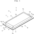
- FIGS. 1 to 6 are diagrams illustrating an all-solid-state battery 10 according to an embodiment.
- an all-solid-state battery will be described as a typical example, but the present disclosure does not necessarily have to be an all-solid-state battery, and application can be made to a battery that has an electrode body and an outer encasement member sealing the electrode body.
- FIG. 1 is an external perspective view
- FIG. 2A is a plan view (as viewed from a direction of arrow II in FIG. 1 )
- FIG. 2B is an enlarged view of a portion surrounded by a dotted line in FIG. 2A
- FIG. 3A is a front view (as viewed from a direction of arrow III in FIG. 1 )
- FIG. 3B is an enlarged view of a portion surrounded by a dotted line in FIG. 3A
- FIG. 4A is a side view (as viewed from a direction of arrow IV in FIG. 1 )
- FIG. 4B is an enlarged view of a portion surrounded by a dotted line in FIG. 4A
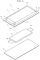
- FIG. 5 is a disassembled perspective view.
- FIG. 6 is part of a sectional view taken along line VI-VI in FIG. 2B .
- the all-solid-state battery 10 has an outer encasement member 11 (a first outer encasement member 12 and a second outer encasement member 13), and an electrode body 14.
- the electrode body 14, which is generally quadrilateral in plan view, is enclosed within the outer encasement member 11, which is generally quadrilateral in plan view.
- an anode terminal 14a and a cathode terminal 14b extend from the electrode body 14, and are disposed such that tip ends thereof protrude from the outer encasement member 11.
- the outer encasement member 11 is made up of a sheet-like member that is quadrilateral in plan view, and in the present embodiment, the outer encasement member 11 includes the first outer encasement member 12 and the second outer encasement member 13.
- the electrode body 14 is enclosed between the first outer encasement member 12 and the second outer encasement member 13, and an outer peripheral end portion of the first outer encasement member 12 and an outer peripheral end portion of the second outer encasement member 13 are joined to form a joint portion 11a. Accordingly, this outer encasement member 11 has a pouch shape, and the electrode body 14 is enclosed and sealed therein.
- the first outer encasement member 12 has a quadrilateral shape in plan view, and has a recessed portion 12a that is quadrilateral in plan view (an opening of the recessed portion 12a is on lower side face in the plane of the drawing in the view in FIG. 5 , and thus is hidden from sight), and the electrode body 14 is accommodated within the recessed portion 12a.
- a flared portion 12b is provided flaring outward from an outer peripheral edge of the recessed portion 12a, and the flared portion 12b and the outer peripheral end portion of a surface of the second outer encasement member 13 are joined to form the joint portion 11a.
- the second outer encasement member 13 has a quadrilateral sheet-like shape in plan view. As described above, the outer peripheral end portion of a face of the second outer encasement member 13 facing the flared portion 12b of the first outer encasement member 12 is overlaid with and joined to the flared portion 12b of the first outer encasement member 12, thereby forming the joint portion 11a.
- the first outer encasement member 12 and the second outer encasement member 13 are made of laminate films.
- a laminate film is a film having a metal layer and a sealant material layer.
- metal and so forth used for the laminate films include aluminum and stainless steel, and examples of material used for the sealant material layer include polypropylene, polyethylene, polystyrene, polyvinyl chloride, and so forth, which are thermoplastic resins.
- the method of joining the first outer encasement member 12 and the second outer encasement member 13, i.e., the method of joining the laminate films, is not limited in particular, and known methods can be used. Specific examples thereof include a method of welding the sealant material layers of the laminate films to each other (e.g., hot plate welding, ultrasound welding, vibration welding, laser welding, or the like) and adhesion by an adhesive.
- the first outer encasement member 12 of the outer encasement member 11 has the following configuration.
- the first outer encasement member 12 is provided with projections 15 at corner portions of the recessed portion 12a that is quadrilateral in plan view, at positions corresponding to corners 10a of the all-solid-state battery 10. Accordingly, in the present embodiment, a total of four projections 15 are provided, one at each corner portion.
- the projections 15 are portions that are continuous with the recessed portion 12a and protrude from the corner portions of the recessed portion 12a, and are formed between the joint portion 11a and the recessed portion 12a.
- the projections 15 are dome-shaped, so as to say, and form hollows 15a surrounded by the projections 15, the second outer encasement member 13, and the electrode body 14, as illustrated in FIG. 6 .
- the projections 15 are not particularly limited as long as the shapes are such that the hollows 15a are formed, the projections 15 can take up the excess material that causes wrinkles in the outer encasement member 11 from twisting, due to the projections 15 being formed between the joint portion 11a and the recessed portion 12a at the corner portions of the recessed portion 12a, thereby suppressing occurrence of wrinkles.
- the projections 15 preferably have a certain level of size, in order to suppress the occurrence of wrinkles at the corner portions of the recessed portion 12a (to take up the excess due to the twisting of the material). That is to say, in the present embodiment, the projections 15 protrude from the recessed portion 12a in each of plan view form ( FIG. 2B ) and front view form ( FIG. 3B ).
- the height H of the projections 15 illustrated in FIGS. 3B , 4B and 6 is, with respect to T that represents the thickness of the recessed portion 12a, at least H ⁇ T, preferably is 0.2 times to 0.8 times the size thereof, and even more preferably is 0.4 times to 0.6 times.
- the protrusion of the projections 15 in plan view (the protrusion indicated by L in FIGS. 2B , 3B , and 6 ) to extend from the corner portion of the recessed portion 12a toward the joint portion 11a.
- the direction thereof is not limited in particular, and in the present embodiment, the projections 15 are configured extending along a long axis of the all-solid-state battery 10 that is rectangular in plan view.
- the projections 15 may be configured extending along a short axis of the all-solid-state battery 10 that is rectangular in plan view as illustrated in FIG. 7 , or the projections 15 may extend along diagonal lines of the all-solid-state battery 10 that is rectangular in plan view as illustrated in FIG. 8 . Further, this is not restrictive either, and the projections 15 may be provided extending in directions therebetween.
- the amount of protrusion of the projections 15 in plan view, indicated by L in FIGS. 2B , 3B , and 6 preferably is 1 mm or more, more preferably is 2 mm or more, and even more preferably is 3 mm or more. While not limited in particular, an upper limit of L preferably is 8 mm or less, and more preferably is 5 mm or less.
- a width W of the projections 15 illustrated in FIGS. 2B and 4B in plan view preferably is 1 mm or more, more preferably is 2 mm or more, and even more preferably is 3 mm or more. While not limited in particular, an upper limit of W preferably is 8 mm or less, and more preferably is 5 mm or less.
- the projection 15 preferably has an inclined face 15b that is inclined toward the joint portion 11a in a thickness direction (the stacking direction of the layers in the electrode body 14). While not limited in particular, the shape of the inclined face 15b may be flat, or may be a convex face as illustrated in FIGS. 3B and 6 . Forming the inclined face 15b as a convex face facilitates ensuring the size of the hollow 15a.
- the connecting portion between the projections 15 and other portions are preferably connected by curved faces. Accordingly, stress concentration can be reduced, and occurrence of tearing can be further suppressed.
- the boundaries between the projections 15 and other portions may become ambiguous, but essentially the projections 15 are portions that are located at the corner portions of the outer encasement member 11 and that protrude so as to extend toward the joint portion 11a of the first outer encasement member 12 and the second outer encasement member 13.
- the projection 15 may be a portion located on a tip end side of an inflection point A illustrated in FIG. 6 , for example.
- the electrode body 14 has anode current collector layers, anode composite material layers, separator layers, cathode composite material layers, cathode current collector layers, the anode terminal 14a, and the cathode terminal 14b.
- the anode current collector layer, the anode composite material layer, the separator layer, the cathode composite material layer, the cathode current collector layer, the cathode composite material layer, the separator layer, the anode composite material layer, and the anode current collector layer are laminated in this order, making up a unit element.
- a plurality thereof is stacked together (also referred to as "laminate 14c"), the anode terminal 14a is electrically connected to the anode current collector layer of the laminate 14c, and the cathode terminal 14b is electrically connected to the cathode current collector layer of the laminate 14c.
- the laminate 14c also is quadrilateral in plan view.
- the anode current collector layer is laminated on the anode composite material layer, and collects electricity from the anode composite material layer.
- the anode current collector layer is foil-like and has a quadrilateral shape in plan view, and is, in the present embodiment, made up of an anode current collector foil that is a metal foil, and a carbon layer laminated on the anode current collector foil.
- the carbon layer is laminated on the anode composite material layer, whereby the anode current collector layer is laminated on the anode composite material layer.
- Examples of the material making up the anode current collector foil include stainless steel, aluminum, nickel, iron, and titanium, and the carbon layer is made of a material containing carbon.
- the anode current collector layer is laminated on one surface of the anode composite material layer, and the separator layer is laminated on the other surface thereof.
- the anode composite material layer is sheet-like, and has a quadrilateral shape in plan view.
- the anode composite material layer is a layer containing an anode active material, and may further contain at least one of a solid electrolyte material, a conductive material, and a binder, as necessary.
- a known active material may be used as the anode active material.
- Examples include cobalt-based materials (LiCoO 2 , etc.), nickel-based materials (LiNiO 2 , etc.), manganese-based materials (LiMn 2 O 4 , Li 2 Mn 2 O 3 , etc.), iron-phosphate-based materials (LiFePO 4 , Li 2 FeP 2 O 7 , etc.), NCA-based materials (nickel, cobalt, and aluminum compounds), NMC-based materials (compounds of nickel, manganese, and cobalt), and so forth. More specific examples include LiNi 1/3 Co 1/3 Mn 1/3 O 2 and so forth.
- the surface of the anode active material may be coated with an oxide layer such as a lithium niobate layer, a lithium titanate layer, a lithium phosphate layer, or the like.
- the solid electrolyte is preferably an inorganic solid electrolyte. This is because ionic conductivity thereof is high and heat resistance thereof is excellent, as compared with organic polymer electrolytes.
- examples of the inorganic solid electrolyte include sulfide solid electrolytes, oxide solid electrolytes, and so forth.
- Examples of the sulfide solid electrolyte material having Lithium-ion conductivity include Li 2 S-P 2 S 5 , Li 2 S-P 2 S 5 -LiI, Li 2 S-P 2 S 5 -Li 2 O, Li 2 S-P 2 S 5 -Li 2 O-LiI, Li 2 S-SiS 2 , Li 2 S-SiS 2 -LiI, Li 2 S-SiS 2 -LiBr, Li 2 S-SiS 2 -LiCl, Li 2 S-SiS 2 -B 2 S 3 -LiI, Li 2 S-SiS 2 -P 2 S 5 -LiI, Li 2 S-B 2 S 3 , Li 2 S-P 2 S 5 -Z m S n (in which m and n are positive numerals, and Z is any of Ge, Zn, and Ga), Li 2 S-GeS 2 , Li 2 S-SiS 2 -Li 3 PO 4
- examples of the oxide solid electrolyte material having Lithium-ion conductivity include compounds having a NASICON (an acronym for sodium (Na) Super Ionic CONductor) type structure, and so forth.
- examples of compounds having a NASICON type structure include a compound (LAGP) represented by the general formula Li 1+x Al x Ge 2-x (PO 4 ) 3 (0 ⁇ x ⁇ 2), a compound (LATP) represented by a general formula Li 1+x Al x Ti 2-x (PO 4 ) 3 (0 ⁇ x ⁇ 2), and so forth.
- oxide solid electrolyte material examples include LiLaTiO (e.g., Li 0.34 La 0.51 TiO 3 ), LiPON (e.g., Li 2.9 PO 3.3 N 0.46 ), LiLaZrO (e.g., Li 7 La 3 Zr 2 O 12 ), and so forth.
- LiLaTiO e.g., Li 0.34 La 0.51 TiO 3
- LiPON e.g., Li 2.9 PO 3.3 N 0.46
- LiLaZrO e.g., Li 7 La 3 Zr 2 O 12
- the binder is not limited in particular as long as it is chemically and electrically stable, and examples thereof include a fluorine-based binder such as polyvinylidene fluoride (PVDF), polytetrafluoroethylene (PTFE), and so forth, rubber-based binders such as styrene-butadiene rubber (SBR) and so forth, olefin-based binders such as polypropylene (PP), polyethylene (PE), and so forth, and cellulose-based binders such as carboxymethyl cellulose (CMC) and so forth.
- PVDF polyvinylidene fluoride
- PTFE polytetrafluoroethylene
- SBR styrene-butadiene rubber
- olefin-based binders such as polypropylene (PP), polyethylene (PE), and so forth
- CMC carboxymethyl cellulose
- Examples of the conductive material that can be used include carbon materials such as acetylene black (AB), Ketjen black, carbon fiber, and so forth, and metal materials such as nickel, aluminum, stainless steel, and so forth.
- carbon materials such as acetylene black (AB), Ketjen black, carbon fiber, and so forth
- metal materials such as nickel, aluminum, stainless steel, and so forth.
- the content of each component in the anode composite material layer may be the same as in conventional arrangements.
- the thickness of the anode composite material layer preferably is, for example, no less than 0.1 ⁇ m and no more than 1 mm, and more preferably no less than 1 ⁇ m and no more than 150 ⁇ m.
- the separator layer (solid electrolyte layer) is sheet-like and has a quadrilateral shape in plan view, is disposed between the anode composite material layer and the cathode composite material layer, and is a layer containing the solid electrolyte material.
- the separator layer contains at least a solid electrolyte material.
- the solid electrolyte material can be thought of in the same way as the solid electrolyte material described regarding the anode composite material layer.
- the cathode composite material layer is a layer containing at least a cathode active material.
- the cathode composite material layer may contain a binder, a conductive material, and a solid electrolyte material, as necessary.
- the binder, the conductive material, and the solid electrolyte material can be thought of in the same way as those in the anode composite material layer.
- examples of the cathode active material include carbon materials such as graphite, hard carbon, and so forth, various types of oxides such as lithium titanate and so forth, silicon (Si) and Si alloys, metallic lithium, lithium alloys, and so forth, but are not limited in particular thereto.
- the cathode composite material layer is sheet-like and has a quadrilateral shape in plan view, with the separator layer laminated on one surface and the cathode current collector layer laminated on the other surface.
- the content of each component in the cathode composite material layer may be the same as in conventional arrangements.
- the thickness of the cathode composite material layer preferably is, for example, no less than 0.1 ⁇ m and no more than 1 mm, and more preferably no less than 1 ⁇ m and no more than 150 ⁇ m.
- the cathode current collector layer is laminated on the cathode composite material layer and collects electricity from the cathode composite material layer.
- the cathode current collector layer is foil-like and has a quadrilateral shape in plan view, and can be made of, for example, stainless steel, copper, nickel, carbon, or the like.
- the anode terminal 14a and the cathode terminal 14b are members that have conductivity, and each is a terminal for externally electrically connecting a respective pole.
- One end of the anode terminal 14a is electrically connected to the anode current collector layers, and the other end penetrates the joint portion 11a between the first outer encasement member 12 and the second outer encasement member 13 and is externally exposed.
- One end of the cathode terminal 14b is electrically connected to the cathode current collector layers, and the other end penetrates the joint portion 11a between the first outer encasement member 12 and the second outer encasement member 13 and is externally exposed.
- the all-solid-state battery 10 can be fabricated by a known method.
- the electrode body 14 is housed inside the recessed portion 12a of the first outer encasement member 12.
- the first outer encasement member 12 and the second outer encasement member 13 are overlaid, and the flared portion 12b of the first outer encasement member 12 and the surface end portion of the second outer encasement member 13 are joined.
- the inside of the recessed portion 12a may be drawn to a vacuum, for deaerating thereof.
- the projections 15 provided on the outer encasement member 11 provided here take up excess of the outer encasement member (laminate sheet) due to twisting that causes wrinkles to occur. Occurrence of wrinkles, which are the starting points of cracks, is suppressed, and accordingly the occurrence of cracks is suppressed, and heat cycle resistance (resistance to occurrence of cracks in the outer encasement member) is improved.
- the strength of the portions where wrinkles are generated can be improved by the projections 15, and from this perspective, occurrence of cracks can be suppressed.
- the outer encasement member (laminate film in particular) is vulnerable to heat cycles (repeated rising and falling temperatures), and when wrinkles occur at the corner portions, stress is concentrated thereat, raising the possibility of cracks occurring.
- the occurrence of cracks can damage the outer encasement member, and cause deterioration of the battery.
- problems can be suppressed by the all-solid-state battery 10.
- the occurrence of wrinkles can be suppressed in any situation.
- the projections may form hollows, and the projections may appear to be deformed, such as being crushed, during the process of manufacturing the battery.
- the effects can be obtained even in a deformed state, as long as the projections have the above-described form even though not discernibly. Accordingly, whether the shape of the projections is within the scope of the present disclosure can be determined from any one of a state in which the battery has been fabricated and become a battery, a state before combining the electrode body with the outer encasement member, and a state of disassembling the battery from the battery state and separating the electrode body from the outer encasement member.
- FIG. 9 is a diagram corresponding to FIG. 6 .
- the second outer encasement member 13 is not used, and two first outer encasement members 12 are overlaid to form an outer encasement member. Accordingly, the opening sides of the recessed portions 12a of the two first outer encasement members 12 are overlaid on each other, and the flared portions 12b thereof are overlaid on each other, and the two flared portions 12b form the joint portion 11a.
- projections 15 are disposed at the corner portions of the electrode body 14, on both sides in the thickness direction of the electrode body 14 (up-down direction in the plane of the drawing, lamination direction of the layers in the laminate 14c of the electrode body 14). Accordingly, as illustrated in FIG. 9 , in the present embodiment, the projections 15 are disposed overlaying each other.
- the two outer encasement members i.e., the first outer encasement member 12 and the second outer encasement member 13 are joined together, but this is not restrictive, and an embodiment may be made in which a single outer encasement member material is folded in half, the electrode body is disposed interposed therebetween, and the outer peripheral end portions of the three sides are joined.
- An electrode body was formed by a known method.
- the specifications of each layer of the electrode body are as follows.
- the outer encasement member was made by processing a laminated sheet.
- the laminate sheet was made up of three layers, which were an insulating resin layer made of polyethylene terephthalate (PET), a metal layer made of aluminum, and a sealing resin layer (sealant material layer) made of polypropylene (PP), and the thickness thereof was 0.15 mm.
- PET polyethylene terephthalate
- PP polypropylene
- the outer shape thereof was 120 mm ⁇ 220 mm in plan view
- the outer shape of the recessed portion was 100 mm ⁇ 200 mm in plan view
- the height of the recessed portion (T in FIG. 3B ) was 5 mm
- the edge was rounded chamfering with a curvature radius of 1 mm.
- the height of the projections was 2.5 mm
- the protrusion amount (L in FIG. 3B ) thereof was 3 mm
- the width (W in FIG. 2B ) thereof was 3 mm.
- the electrode body was sealed in the outer encasement member having the projections.
- the electrode body was sealed in an outer encasement member having no projections.
- a heat cycle test was performed on the all-solid-state battery that was fabricated. Specifically, the prescribed temperature on the high temperature side was 100°C, and the prescribed temperature on the low temperature side was -20°C, with each cycle being set to 30 minutes, and this cycle being repeated 2000 times.
- the all-solid-state battery that was fabricated was placed in a constant temperature bath that exchanges high and low-temperature air layers, and inside of the layer was made to reach the prescribed temperature in around 10 minutes, and testing was carried out such that the temperature of the all-solid-state battery was at the prescribed temperature for at least five minutes or more.
Landscapes
- Chemical & Material Sciences (AREA)
- Chemical Kinetics & Catalysis (AREA)
- Electrochemistry (AREA)
- General Chemical & Material Sciences (AREA)
- Engineering & Computer Science (AREA)
- Manufacturing & Machinery (AREA)
- Sealing Battery Cases Or Jackets (AREA)
- Secondary Cells (AREA)
Applications Claiming Priority (1)
| Application Number | Priority Date | Filing Date | Title |
|---|---|---|---|
| JP2022000549A JP2023100111A (ja) | 2022-01-05 | 2022-01-05 | 電池 |
Publications (1)
| Publication Number | Publication Date |
|---|---|
| EP4210137A1 true EP4210137A1 (fr) | 2023-07-12 |
Family
ID=84536124
Family Applications (1)
| Application Number | Title | Priority Date | Filing Date |
|---|---|---|---|
| EP22213354.8A Pending EP4210137A1 (fr) | 2022-01-05 | 2022-12-14 | Batterie |
Country Status (5)
| Country | Link |
|---|---|
| US (1) | US20230216119A1 (fr) |
| EP (1) | EP4210137A1 (fr) |
| JP (1) | JP2023100111A (fr) |
| KR (1) | KR20230106104A (fr) |
| CN (1) | CN116454490A (fr) |
Citations (7)
| Publication number | Priority date | Publication date | Assignee | Title |
|---|---|---|---|---|
| JP2004039271A (ja) | 2002-06-28 | 2004-02-05 | Nissan Motor Co Ltd | 電池外装ケースの密封構造 |
| US20150333358A1 (en) * | 2013-01-21 | 2015-11-19 | Sanyo Electric Co., Ltd. | Laminated battery and manufacturing method therefor |
| US20160248053A1 (en) * | 2015-02-24 | 2016-08-25 | Panasonic Intellectual Property Management Co., Ltd. | Flexible battery |
| KR101762669B1 (ko) * | 2014-10-31 | 2017-07-28 | 주식회사 엘지화학 | 주름 방지용 부재가 부가되어 있는 전지셀 |
| JP2020013637A (ja) * | 2018-07-13 | 2020-01-23 | 日産自動車株式会社 | 電池 |
| EP3552257B1 (fr) * | 2016-12-06 | 2021-01-27 | Robert Bosch GmbH | Dispositif et procédé pour former des joints scellés de coin ondulés dans un matériau en feuille stratifié |
| KR20210073886A (ko) * | 2019-12-11 | 2021-06-21 | 삼성에스디아이 주식회사 | 배터리 팩 및 라벨 시트 |
-
2022
- 2022-01-05 JP JP2022000549A patent/JP2023100111A/ja active Pending
- 2022-12-14 CN CN202211605996.XA patent/CN116454490A/zh active Pending
- 2022-12-14 EP EP22213354.8A patent/EP4210137A1/fr active Pending
- 2022-12-15 KR KR1020220175764A patent/KR20230106104A/ko unknown
- 2022-12-21 US US18/085,978 patent/US20230216119A1/en active Pending
Patent Citations (7)
| Publication number | Priority date | Publication date | Assignee | Title |
|---|---|---|---|---|
| JP2004039271A (ja) | 2002-06-28 | 2004-02-05 | Nissan Motor Co Ltd | 電池外装ケースの密封構造 |
| US20150333358A1 (en) * | 2013-01-21 | 2015-11-19 | Sanyo Electric Co., Ltd. | Laminated battery and manufacturing method therefor |
| KR101762669B1 (ko) * | 2014-10-31 | 2017-07-28 | 주식회사 엘지화학 | 주름 방지용 부재가 부가되어 있는 전지셀 |
| US20160248053A1 (en) * | 2015-02-24 | 2016-08-25 | Panasonic Intellectual Property Management Co., Ltd. | Flexible battery |
| EP3552257B1 (fr) * | 2016-12-06 | 2021-01-27 | Robert Bosch GmbH | Dispositif et procédé pour former des joints scellés de coin ondulés dans un matériau en feuille stratifié |
| JP2020013637A (ja) * | 2018-07-13 | 2020-01-23 | 日産自動車株式会社 | 電池 |
| KR20210073886A (ko) * | 2019-12-11 | 2021-06-21 | 삼성에스디아이 주식회사 | 배터리 팩 및 라벨 시트 |
Also Published As
| Publication number | Publication date |
|---|---|
| US20230216119A1 (en) | 2023-07-06 |
| KR20230106104A (ko) | 2023-07-12 |
| CN116454490A (zh) | 2023-07-18 |
| JP2023100111A (ja) | 2023-07-18 |
Similar Documents
| Publication | Publication Date | Title |
|---|---|---|
| JP5830953B2 (ja) | 二次電池、バッテリユニットおよびバッテリモジュール | |
| KR101304108B1 (ko) | 각형 전지 | |
| JP5591569B2 (ja) | 角形電池及びその製造方法ならびにこれを用いてなる組電池 | |
| JP6250921B2 (ja) | 電池 | |
| US20120202105A1 (en) | Stack type battery and method of manufacturing the same | |
| US20120244423A1 (en) | Laminate case secondary battery | |
| US20210119285A1 (en) | Battery cell | |
| JP4096718B2 (ja) | バイポーラ電池、バイポーラ電池の製造方法、組電池および車両 | |
| JP2007066806A (ja) | バイポーラ電池 | |
| US20110076544A1 (en) | Stack type battery | |
| EP3660940B1 (fr) | Batterie et dispositif | |
| US11417911B2 (en) | All-solid-state battery and method for producing the same | |
| JP4670275B2 (ja) | バイポーラ電池および組電池 | |
| JP6178183B2 (ja) | 非水電解質電池、組電池及び蓄電池装置 | |
| CN115191047A (zh) | 集电体、蓄电元件和蓄电模块 | |
| JP2020173989A (ja) | 非水電解質二次電池 | |
| EP4210137A1 (fr) | Batterie | |
| KR101722662B1 (ko) | 파우치형 이차 전지 | |
| JP2013012343A (ja) | パウチ型リチウム二次電池 | |
| KR20230044022A (ko) | 전기화학 디바이스 및 전자 디바이스 | |
| US20230147419A1 (en) | All-solid-state battery | |
| KR102052920B1 (ko) | 밀봉용 폴딩부를 포함하는 전지셀 | |
| JP2010021043A (ja) | セパレータ、セパレータの製造方法および電池 | |
| JP5954339B2 (ja) | 角形二次電池及びその製造方法 | |
| JP7343413B2 (ja) | 電池セル |
Legal Events
| Date | Code | Title | Description |
|---|---|---|---|
| PUAI | Public reference made under article 153(3) epc to a published international application that has entered the european phase |
Free format text: ORIGINAL CODE: 0009012 |
|
| STAA | Information on the status of an ep patent application or granted ep patent |
Free format text: STATUS: REQUEST FOR EXAMINATION WAS MADE |
|
| 17P | Request for examination filed |
Effective date: 20221214 |
|
| AK | Designated contracting states |
Kind code of ref document: A1 Designated state(s): AL AT BE BG CH CY CZ DE DK EE ES FI FR GB GR HR HU IE IS IT LI LT LU LV MC ME MK MT NL NO PL PT RO RS SE SI SK SM TR |