EP4209727A1 - Unité extérieure de climatiseur - Google Patents
Unité extérieure de climatiseur Download PDFInfo
- Publication number
- EP4209727A1 EP4209727A1 EP20952477.6A EP20952477A EP4209727A1 EP 4209727 A1 EP4209727 A1 EP 4209727A1 EP 20952477 A EP20952477 A EP 20952477A EP 4209727 A1 EP4209727 A1 EP 4209727A1
- Authority
- EP
- European Patent Office
- Prior art keywords
- heat exchanger
- group
- outdoor
- refrigerant
- expansion valve
- Prior art date
- Legal status (The legal status is an assumption and is not a legal conclusion. Google has not performed a legal analysis and makes no representation as to the accuracy of the status listed.)
- Pending
Links
- 239000003507 refrigerant Substances 0.000 claims abstract description 85
- 238000004781 supercooling Methods 0.000 claims abstract description 26
- 238000011144 upstream manufacturing Methods 0.000 claims abstract description 6
- 238000001816 cooling Methods 0.000 abstract description 31
- 238000007599 discharging Methods 0.000 abstract 1
- 239000007788 liquid Substances 0.000 description 34
- 239000000470 constituent Substances 0.000 description 16
- 238000004378 air conditioning Methods 0.000 description 7
- 230000006866 deterioration Effects 0.000 description 6
- 238000009833 condensation Methods 0.000 description 4
- 230000005494 condensation Effects 0.000 description 4
- 238000010438 heat treatment Methods 0.000 description 4
- 238000010586 diagram Methods 0.000 description 2
- 229910000838 Al alloy Inorganic materials 0.000 description 1
- RYGMFSIKBFXOCR-UHFFFAOYSA-N Copper Chemical compound [Cu] RYGMFSIKBFXOCR-UHFFFAOYSA-N 0.000 description 1
- 239000006096 absorbing agent Substances 0.000 description 1
- XAGFODPZIPBFFR-UHFFFAOYSA-N aluminium Chemical compound [Al] XAGFODPZIPBFFR-UHFFFAOYSA-N 0.000 description 1
- 229910052782 aluminium Inorganic materials 0.000 description 1
- 229910052802 copper Inorganic materials 0.000 description 1
- 239000010949 copper Substances 0.000 description 1
- 238000011010 flushing procedure Methods 0.000 description 1
- 230000020169 heat generation Effects 0.000 description 1
- 238000009434 installation Methods 0.000 description 1
- 239000000314 lubricant Substances 0.000 description 1
- 239000000463 material Substances 0.000 description 1
- 230000004048 modification Effects 0.000 description 1
- 238000012986 modification Methods 0.000 description 1
- 238000006467 substitution reaction Methods 0.000 description 1
Images


Classifications
-
- F—MECHANICAL ENGINEERING; LIGHTING; HEATING; WEAPONS; BLASTING
- F24—HEATING; RANGES; VENTILATING
- F24F—AIR-CONDITIONING; AIR-HUMIDIFICATION; VENTILATION; USE OF AIR CURRENTS FOR SCREENING
- F24F1/00—Room units for air-conditioning, e.g. separate or self-contained units or units receiving primary air from a central station
- F24F1/06—Separate outdoor units, e.g. outdoor unit to be linked to a separate room comprising a compressor and a heat exchanger
- F24F1/20—Electric components for separate outdoor units
- F24F1/24—Cooling of electric components
-
- F—MECHANICAL ENGINEERING; LIGHTING; HEATING; WEAPONS; BLASTING
- F24—HEATING; RANGES; VENTILATING
- F24F—AIR-CONDITIONING; AIR-HUMIDIFICATION; VENTILATION; USE OF AIR CURRENTS FOR SCREENING
- F24F1/00—Room units for air-conditioning, e.g. separate or self-contained units or units receiving primary air from a central station
- F24F1/06—Separate outdoor units, e.g. outdoor unit to be linked to a separate room comprising a compressor and a heat exchanger
- F24F1/14—Heat exchangers specially adapted for separate outdoor units
- F24F1/16—Arrangement or mounting thereof
-
- F—MECHANICAL ENGINEERING; LIGHTING; HEATING; WEAPONS; BLASTING
- F25—REFRIGERATION OR COOLING; COMBINED HEATING AND REFRIGERATION SYSTEMS; HEAT PUMP SYSTEMS; MANUFACTURE OR STORAGE OF ICE; LIQUEFACTION SOLIDIFICATION OF GASES
- F25B—REFRIGERATION MACHINES, PLANTS OR SYSTEMS; COMBINED HEATING AND REFRIGERATION SYSTEMS; HEAT PUMP SYSTEMS
- F25B31/00—Compressor arrangements
- F25B31/006—Cooling of compressor or motor
-
- F—MECHANICAL ENGINEERING; LIGHTING; HEATING; WEAPONS; BLASTING
- F25—REFRIGERATION OR COOLING; COMBINED HEATING AND REFRIGERATION SYSTEMS; HEAT PUMP SYSTEMS; MANUFACTURE OR STORAGE OF ICE; LIQUEFACTION SOLIDIFICATION OF GASES
- F25B—REFRIGERATION MACHINES, PLANTS OR SYSTEMS; COMBINED HEATING AND REFRIGERATION SYSTEMS; HEAT PUMP SYSTEMS
- F25B40/00—Subcoolers, desuperheaters or superheaters
- F25B40/02—Subcoolers
-
- F—MECHANICAL ENGINEERING; LIGHTING; HEATING; WEAPONS; BLASTING
- F25—REFRIGERATION OR COOLING; COMBINED HEATING AND REFRIGERATION SYSTEMS; HEAT PUMP SYSTEMS; MANUFACTURE OR STORAGE OF ICE; LIQUEFACTION SOLIDIFICATION OF GASES
- F25B—REFRIGERATION MACHINES, PLANTS OR SYSTEMS; COMBINED HEATING AND REFRIGERATION SYSTEMS; HEAT PUMP SYSTEMS
- F25B49/00—Arrangement or mounting of control or safety devices
- F25B49/02—Arrangement or mounting of control or safety devices for compression type machines, plants or systems
-
- F—MECHANICAL ENGINEERING; LIGHTING; HEATING; WEAPONS; BLASTING
- F25—REFRIGERATION OR COOLING; COMBINED HEATING AND REFRIGERATION SYSTEMS; HEAT PUMP SYSTEMS; MANUFACTURE OR STORAGE OF ICE; LIQUEFACTION SOLIDIFICATION OF GASES
- F25B—REFRIGERATION MACHINES, PLANTS OR SYSTEMS; COMBINED HEATING AND REFRIGERATION SYSTEMS; HEAT PUMP SYSTEMS
- F25B6/00—Compression machines, plants or systems, with several condenser circuits
- F25B6/02—Compression machines, plants or systems, with several condenser circuits arranged in parallel
-
- H—ELECTRICITY
- H05—ELECTRIC TECHNIQUES NOT OTHERWISE PROVIDED FOR
- H05K—PRINTED CIRCUITS; CASINGS OR CONSTRUCTIONAL DETAILS OF ELECTRIC APPARATUS; MANUFACTURE OF ASSEMBLAGES OF ELECTRICAL COMPONENTS
- H05K7/00—Constructional details common to different types of electric apparatus
- H05K7/20—Modifications to facilitate cooling, ventilating, or heating
- H05K7/20218—Modifications to facilitate cooling, ventilating, or heating using a liquid coolant without phase change in electronic enclosures
- H05K7/20254—Cold plates transferring heat from heat source to coolant
-
- H—ELECTRICITY
- H05—ELECTRIC TECHNIQUES NOT OTHERWISE PROVIDED FOR
- H05K—PRINTED CIRCUITS; CASINGS OR CONSTRUCTIONAL DETAILS OF ELECTRIC APPARATUS; MANUFACTURE OF ASSEMBLAGES OF ELECTRICAL COMPONENTS
- H05K7/00—Constructional details common to different types of electric apparatus
- H05K7/20—Modifications to facilitate cooling, ventilating, or heating
- H05K7/20218—Modifications to facilitate cooling, ventilating, or heating using a liquid coolant without phase change in electronic enclosures
- H05K7/20272—Accessories for moving fluid, for expanding fluid, for connecting fluid conduits, for distributing fluid, for removing gas or for preventing leakage, e.g. pumps, tanks or manifolds
-
- H—ELECTRICITY
- H05—ELECTRIC TECHNIQUES NOT OTHERWISE PROVIDED FOR
- H05K—PRINTED CIRCUITS; CASINGS OR CONSTRUCTIONAL DETAILS OF ELECTRIC APPARATUS; MANUFACTURE OF ASSEMBLAGES OF ELECTRICAL COMPONENTS
- H05K7/00—Constructional details common to different types of electric apparatus
- H05K7/20—Modifications to facilitate cooling, ventilating, or heating
- H05K7/2089—Modifications to facilitate cooling, ventilating, or heating for power electronics, e.g. for inverters for controlling motor
- H05K7/20927—Liquid coolant without phase change
-
- F—MECHANICAL ENGINEERING; LIGHTING; HEATING; WEAPONS; BLASTING
- F24—HEATING; RANGES; VENTILATING
- F24F—AIR-CONDITIONING; AIR-HUMIDIFICATION; VENTILATION; USE OF AIR CURRENTS FOR SCREENING
- F24F1/00—Room units for air-conditioning, e.g. separate or self-contained units or units receiving primary air from a central station
- F24F1/06—Separate outdoor units, e.g. outdoor unit to be linked to a separate room comprising a compressor and a heat exchanger
- F24F1/46—Component arrangements in separate outdoor units
- F24F1/48—Component arrangements in separate outdoor units characterised by air airflow, e.g. inlet or outlet airflow
- F24F1/50—Component arrangements in separate outdoor units characterised by air airflow, e.g. inlet or outlet airflow with outlet air in upward direction
-
- F—MECHANICAL ENGINEERING; LIGHTING; HEATING; WEAPONS; BLASTING
- F25—REFRIGERATION OR COOLING; COMBINED HEATING AND REFRIGERATION SYSTEMS; HEAT PUMP SYSTEMS; MANUFACTURE OR STORAGE OF ICE; LIQUEFACTION SOLIDIFICATION OF GASES
- F25B—REFRIGERATION MACHINES, PLANTS OR SYSTEMS; COMBINED HEATING AND REFRIGERATION SYSTEMS; HEAT PUMP SYSTEMS
- F25B13/00—Compression machines, plants or systems, with reversible cycle
-
- F—MECHANICAL ENGINEERING; LIGHTING; HEATING; WEAPONS; BLASTING
- F25—REFRIGERATION OR COOLING; COMBINED HEATING AND REFRIGERATION SYSTEMS; HEAT PUMP SYSTEMS; MANUFACTURE OR STORAGE OF ICE; LIQUEFACTION SOLIDIFICATION OF GASES
- F25B—REFRIGERATION MACHINES, PLANTS OR SYSTEMS; COMBINED HEATING AND REFRIGERATION SYSTEMS; HEAT PUMP SYSTEMS
- F25B2313/00—Compression machines, plants or systems with reversible cycle not otherwise provided for
- F25B2313/025—Compression machines, plants or systems with reversible cycle not otherwise provided for using multiple outdoor units
- F25B2313/0253—Compression machines, plants or systems with reversible cycle not otherwise provided for using multiple outdoor units in parallel arrangements
-
- F—MECHANICAL ENGINEERING; LIGHTING; HEATING; WEAPONS; BLASTING
- F25—REFRIGERATION OR COOLING; COMBINED HEATING AND REFRIGERATION SYSTEMS; HEAT PUMP SYSTEMS; MANUFACTURE OR STORAGE OF ICE; LIQUEFACTION SOLIDIFICATION OF GASES
- F25B—REFRIGERATION MACHINES, PLANTS OR SYSTEMS; COMBINED HEATING AND REFRIGERATION SYSTEMS; HEAT PUMP SYSTEMS
- F25B2313/00—Compression machines, plants or systems with reversible cycle not otherwise provided for
- F25B2313/031—Sensor arrangements
- F25B2313/0315—Temperature sensors near the outdoor heat exchanger
-
- F—MECHANICAL ENGINEERING; LIGHTING; HEATING; WEAPONS; BLASTING
- F25—REFRIGERATION OR COOLING; COMBINED HEATING AND REFRIGERATION SYSTEMS; HEAT PUMP SYSTEMS; MANUFACTURE OR STORAGE OF ICE; LIQUEFACTION SOLIDIFICATION OF GASES
- F25B—REFRIGERATION MACHINES, PLANTS OR SYSTEMS; COMBINED HEATING AND REFRIGERATION SYSTEMS; HEAT PUMP SYSTEMS
- F25B2500/00—Problems to be solved
- F25B2500/01—Geometry problems, e.g. for reducing size
-
- F—MECHANICAL ENGINEERING; LIGHTING; HEATING; WEAPONS; BLASTING
- F25—REFRIGERATION OR COOLING; COMBINED HEATING AND REFRIGERATION SYSTEMS; HEAT PUMP SYSTEMS; MANUFACTURE OR STORAGE OF ICE; LIQUEFACTION SOLIDIFICATION OF GASES
- F25B—REFRIGERATION MACHINES, PLANTS OR SYSTEMS; COMBINED HEATING AND REFRIGERATION SYSTEMS; HEAT PUMP SYSTEMS
- F25B2600/00—Control issues
- F25B2600/02—Compressor control
- F25B2600/021—Inverters therefor
-
- F—MECHANICAL ENGINEERING; LIGHTING; HEATING; WEAPONS; BLASTING
- F25—REFRIGERATION OR COOLING; COMBINED HEATING AND REFRIGERATION SYSTEMS; HEAT PUMP SYSTEMS; MANUFACTURE OR STORAGE OF ICE; LIQUEFACTION SOLIDIFICATION OF GASES
- F25B—REFRIGERATION MACHINES, PLANTS OR SYSTEMS; COMBINED HEATING AND REFRIGERATION SYSTEMS; HEAT PUMP SYSTEMS
- F25B2600/00—Control issues
- F25B2600/25—Control of valves
- F25B2600/2503—Condenser exit valves
-
- F—MECHANICAL ENGINEERING; LIGHTING; HEATING; WEAPONS; BLASTING
- F25—REFRIGERATION OR COOLING; COMBINED HEATING AND REFRIGERATION SYSTEMS; HEAT PUMP SYSTEMS; MANUFACTURE OR STORAGE OF ICE; LIQUEFACTION SOLIDIFICATION OF GASES
- F25B—REFRIGERATION MACHINES, PLANTS OR SYSTEMS; COMBINED HEATING AND REFRIGERATION SYSTEMS; HEAT PUMP SYSTEMS
- F25B2700/00—Sensing or detecting of parameters; Sensors therefor
- F25B2700/19—Pressures
- F25B2700/193—Pressures of the compressor
- F25B2700/1931—Discharge pressures
-
- F—MECHANICAL ENGINEERING; LIGHTING; HEATING; WEAPONS; BLASTING
- F25—REFRIGERATION OR COOLING; COMBINED HEATING AND REFRIGERATION SYSTEMS; HEAT PUMP SYSTEMS; MANUFACTURE OR STORAGE OF ICE; LIQUEFACTION SOLIDIFICATION OF GASES
- F25B—REFRIGERATION MACHINES, PLANTS OR SYSTEMS; COMBINED HEATING AND REFRIGERATION SYSTEMS; HEAT PUMP SYSTEMS
- F25B2700/00—Sensing or detecting of parameters; Sensors therefor
- F25B2700/21—Temperatures
- F25B2700/2116—Temperatures of a condenser
- F25B2700/21163—Temperatures of a condenser of the refrigerant at the outlet of the condenser
-
- F—MECHANICAL ENGINEERING; LIGHTING; HEATING; WEAPONS; BLASTING
- F25—REFRIGERATION OR COOLING; COMBINED HEATING AND REFRIGERATION SYSTEMS; HEAT PUMP SYSTEMS; MANUFACTURE OR STORAGE OF ICE; LIQUEFACTION SOLIDIFICATION OF GASES
- F25B—REFRIGERATION MACHINES, PLANTS OR SYSTEMS; COMBINED HEATING AND REFRIGERATION SYSTEMS; HEAT PUMP SYSTEMS
- F25B41/00—Fluid-circulation arrangements
- F25B41/30—Expansion means; Dispositions thereof
- F25B41/39—Dispositions with two or more expansion means arranged in series, i.e. multi-stage expansion, on a refrigerant line leading to the same evaporator
Definitions
- Embodiments of the present invention relate to an outdoor unit of an air conditioner.
- a mechanism configured to cool electrical components involving heat generation and incorporated in the outdoor unit such as switching elements of an inverter, circuit board or the like on which the aforementioned elements are mounted is provided.
- a refrigerant-cooled heat sink (hereinafter simply referred to as a heat sink) configured to cool electrical components with a refrigerant is given.
- the heat sink is provided on a refrigerant flow path on the downstream side of, for example, a single heat exchanger (condenser) provided in the outdoor unit or at a flow path position which is on the downstream side of a plurality of heat exchangers (condensers) connected in parallel with each other and at which refrigerant (condensed liquid refrigerant) branches outflowing from the heat exchangers join each other.
- the cooling effect of the heat sink changes depending on the temperature and circulating volume of the liquid refrigerant condensed by the heat exchanger (condenser). For example, when the liquid refrigerant temperature is low and refrigerant circulating volume is large, the cooling effect of the heat sink becomes greater.
- the cooling effect of the heat sink in the air-cooled condenser becomes greater to such a degree that the temperature of the liquid refrigerant is lowered to the temperature of the sucked air passing through the aforementioned condenser.
- the degree of opening of the expansion valve provided on the downstream side of the condenser is made smaller and refrigerant circulating volume is thereby adjusted.
- the temperature of the liquid refrigerant can be lowered by tightening the expansion valve
- flushing is caused by the pressure rise of the high-temperature/high-pressure gas to be discharged from the compressor and liquid-pressure drop on the secondary side of the expansion valve.
- the performance of the air conditioner more specifically, the cooling capability thereof is deteriorated.
- Patent Literature 1 JP 2011-117677 A
- the present invention has been contrived in light of the aforementioned circumstances, and an embodiment described herein aims to provide an air conditioner capable of acquiring the cooling effect of electrical components by means of a refrigerant-cooled heat sink while suppressing deterioration in the cooling capability thereof.
- An outdoor unit of an air conditioner includes a compressor which discharges a refrigerant into a flow path, a heat exchanger, an expansion valve, a blower fan, electrical components which control the compressor and the blower fan, and a heat sink which cools the electrical components by the refrigerant.
- the heat exchanger is formed in such a manner that a plurality of heat exchangers are connected in parallel with each other, and includes a heat exchanger of a first group constituted of at least one of the plurality of heat exchangers and a heat exchanger of a second group constituted of at least one of the plurality of heat exchangers not belonging to the first group.
- the expansion valve includes a first expansion valve which adjusts a degree of supercooling of the heat exchanger of the first group and a second expansion valve which adjusts a degree of supercooling of the heat exchanger of the second group.
- the heat sink is arranged on the flow path of the refrigerant on the upstream side of a confluence position of the refrigerant branches condensed by the heat exchangers of the first group and the second group and on the downstream side of the second expansion valve.
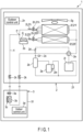
- FIG. 1 is a circuit diagram schematically showing the configuration of an air conditioner 1 according to this embodiment.
- the air conditioner 1 includes an outdoor unit 2 and indoor unit 3.
- the outdoor unit 2 and indoor unit 3 are connected to each other by a flow path 4 through which a refrigerant is circulated between both the units 2 and 3.
- the outdoor unit 2 is installed on a roof of a building and indoor unit 3 is installed in the ceiling space or the like of each floor of the building.
- the installation locations of the units 2 and 3 are not limited to the aforementioned places.
- the outdoor unit 2 includes, as main elements, a compressor 2a, oil separator 2b, high-pressure sensor 2c, check valve 2d, four-way valve 2e, heat exchanger(s) (hereinafter referred to as an outdoor heat exchanger) 2f, blower fan (hereinafter referred to as an outdoor fan) 2g, expansion valve(s) (hereinafter referred to as an outdoor expansion valve) 2h, temperature sensor(s) 2i, refrigerant-cooled heat sink (hereinafter referred to as a heat sink) 2j, on-off valve(s) 2k, accumulator 21, and suction cup 2m.
- a compressor 2a as oil separator 2b, high-pressure sensor 2c, check valve 2d, four-way valve 2e
- heat exchanger(s) hereinafter referred to as an outdoor heat exchanger
- blower fan hereinafter referred to as an outdoor fan
- expansion valve(s) hereinafter referred to as an outdoor expansion valve
- temperature sensor(s) 2i hereinafter
- the elements other than the outdoor fan 2g are piping-connected to each other inside a housing 21 and are each arranged in or on the flow path 4 connected to the indoor unit 3.
- the outdoor fan 2g is arranged above the outdoor heat exchanger 2f.
- the housing 21 defines a contour of the outdoor unit 2. It should be noted that the above-described elements 2a to 2m may not be arranged in one housing 21 and may also be arranged dispersedly in a plurality of housings.
- the outdoor unit 2 includes a control unit (hereinafter referred to as an outdoor control unit) 2n and inverter 2o.
- the outdoor control unit 2n controls operations of the outdoor unit 2 and carries out switching between a cooling operation and heating operation.
- the inverter 2o rectifies a voltage of a commercial AC source (illustration omitted), frequency-converts the rectified voltage according to an instruction from the outdoor control unit 2n, and outputs the frequency-converted voltage to the compressor 2a and outdoor fan 2g.
- the inverter 2o includes electrical components configured to control the compressor 2a and outdoor fan 2g as described above.
- the aforementioned electrical components are, for example, heat-producing components such as switching elements, and circuit board or the like on which the aforementioned elements are mounted, and are refrigerant-cooled by the heat sink 2j.
- the indoor unit 3 includes, as main elements, an expansion valve (hereinafter referred to as an indoor expansion valve) 3a, heat exchanger (hereinafter referred to as an indoor heat exchanger) 3b, blower fan (hereinafter referred to as an indoor fan) 3c, and control unit (hereinafter referred to as an indoor control unit) 3d.
- the indoor expansion valve 3a and indoor heat exchanger 3b are piping-connected to each other inside the housing 31 and are each arranged in the flow path 4 connected to the outdoor unit 2.
- the indoor fan 3c is arranged in the vicinity of the indoor heat exchanger 3b inside the housing 31.
- the housing 31 defines a contour of the indoor unit 3.
- the indoor control unit 3d includes, for example, a panel, switches, and buttons all of which are used for operation, display for displaying, and the like and controls a start of operation of the indoor unit 3, mode selection between the cooling operation and heating operation, indoor temperature, and the like. It should be noted that although in FIG. 1 , only one indoor unit 3 is shown as an example, a plurality of indoor units 3 may also be provided.
- the four-way valve 2e is switched in such a manner that the high-temperature/high-pressure gaseous refrigerant compressed by the compressor 2a is discharged into the flow path 4.
- the discharged gaseous refrigerant is passed through the check valve 2d, is separated from the contained lubricant component by the oil separator 2b and is thereafter guided to the outdoor heat exchanger 2f functioning as a condenser (heat radiator) through the four-way valve 2e.
- the gaseous refrigerant guided to the outdoor heat exchanger 2f is condensed by heat exchange with air and is changed into a high-pressure liquid refrigerant.
- the high-pressure liquid refrigerant is adjusted for the degree of supercooling to be described later by the outdoor expansion valve 2h, is decompressed in the course of passage thereof through the indoor expansion valve 3a, and is thereby changed into a low-pressure liquid refrigerant.
- the aforementioned liquid refrigerant is guided to the indoor heat exchanger 3b functioning as an evaporator (heat absorber) and, at the same time, carries out heat exchange with air in the course of passage thereof through the indoor heat exchanger 3b.
- the liquid refrigerant takes heat from the air to thereby evaporate and changes into a low-temperature/low-pressure gaseous refrigerant.
- the air passing through the indoor heat exchanger 3b is cooled by heat exchange with the liquid refrigerant and is blown toward the place to be air-conditioned (cooled) as cool air by the indoor fan 3c.
- the low-temperature/low-pressure gaseous refrigerant passing through the indoor heat exchanger 3b is guided to the accumulator 21 through the four-way valve 2e.
- the refrigerant is separated here into the liquid refrigerant and gaseous refrigerant.
- the low-temperature/low pressure gaseous refrigerant separated from the liquid refrigerant is sucked into the compressor 2a from the accumulator 21 and, at the same time, is compressed again by the compressor 2a into a high-temperature/high-pressure gaseous refrigerant to thereby be discharged into the flow path 4.
- the four-way valve 2e is switched in such a manner that the high-temperature/high-pressure gaseous refrigerant discharged from the compressor 2a is guided to the indoor heat exchanger 3b through the four-way valve 2e and is made to carry out heat exchange with air passing through the indoor heat exchanger 3b.
- the indoor heat exchanger 3b functions as a condenser.
- the gaseous refrigerant passing through the indoor heat exchanger 3b is condensed by carrying out heat exchange with the air and is changed into a high-pressure liquid refrigerant.
- the air passing through the indoor heat exchanger 3b is heated by heat exchange with the gaseous refrigerant and is blown toward the place to be air-conditioned (heated) as a warm current of air by the indoor fan 3c.
- the high-temperature liquid refrigerant passing through the indoor heat exchanger 3b is guided to the outdoor expansion valve 2h and, at the same time, is decompressed in the course of passage thereof through the outdoor expansion valve 2h to thereby be changed into a low-pressure liquid refrigerant.
- the aforementioned liquid refrigerant is guided to the outdoor heat exchanger 2f functioning as an evaporator and, at the same time, is evaporated by carrying out heat exchange here with air to thereby be changed into a low-temperature/low-pressure gaseous refrigerant.
- the low-temperature/low-pressure gaseous refrigerant passing through the outdoor heat exchanger 2f is sucked into the compressor 2a through the four-way valve 2e and accumulator 21 and, at the same time, is compressed again by the compressor 2a into a high-temperature/high-pressure gaseous refrigerant to thereby be discharged into the flow path 4.
- the outdoor heat exchanger 2f of the outdoor unit 2 is constituted of heat exchangers of two groups.
- Each of the heat exchangers of the two groups is constituted of at least one heat exchanger (outdoor heat exchanger) and the heat exchangers are connected in parallel with each other. More specifically, one (hereinafter referred to as a first group) of the two groups is constituted of at least one outdoor heat exchanger and the other (hereinafter referred to as a second group) is constituted of at least one outdoor heat exchanger not belonging to the first group.
- an outdoor heat exchanger 21f belongs to the first group and outdoor heat exchanger 22f belongs to the second group. That is, in this example, each of the outdoor heat exchangers 2f of the first group and second group is constituted of one outdoor heat exchanger 21f or 22f. However, each of the outdoor heat exchangers 2f of the first group and second group may also be constituted of a plurality of outdoor heat exchangers.
- FIG. 2 is a schematic view schematically showing the configuration of the outdoor unit 2 from the horizontal direction.
- the outdoor heat exchangers 21f and 22f are provided at two opposed side surface portions S1 and S2 of the housing 21 of the outdoor unit 2 formed into, for example, approximately a rectangular parallelepiped.
- the outdoor heat exchanger 21f is divided into two constituents (hereinafter referred to as heat exchanger constituents) 211f and 212f respectively adjacent to these two side surface portions S1 and S2 opposed to each other.
- the outdoor heat exchanger 22f is divided into two heat exchanger constituents 221f and 222f respectively adjacent to these two side surface portions S1 and S2 opposed to each other.
- outside-air suction openings (illustration omitted) are formed.
- the outdoor fan 2g When the outdoor fan 2g is driven, the outside air is sucked into the inside of the housing 21 from the suction openings of the side surface portions S1 and S2 through the outdoor heat exchangers 21f and 22f as indicated by arrows A1 and A2 and is discharged to the outside of the housing 21 through the outdoor fan 2g as indicated by an arrow A3.
- the outdoor heat exchanger 22f which is the heat exchanger of the second group, outdoor heat exchanger 21f which is the heat exchanger of the first group, and blower fan (outdoor fan) 2g are arranged inside the housing 21, in sequence from below in the vertical direction (from the bottom face portion in FIG. 2 ). That is, the outdoor heat exchanger 21f is arranged closer to the outdoor fan 2g than the outdoor heat exchanger 22f. For this reason, as indicated by the arrows A1 and A2 in FIG. 2 , when the outdoor fan 2g is driven, the outside air can be sucked into the inside of the housing 21 more easily at the arrangement portion of the outdoor heat exchanger 21f closer to the outdoor fan 2g than at the arrangement portion of the outdoor heat exchanger 22f.
- the volume and velocity of the wind (air) to be sucked into the inside of the housing 21 are more liable to become greater at the arrangement portion of the outdoor heat exchanger 21f than at the arrangement portion of the outdoor heat exchanger 22f. Accordingly, the efficiency of the heat exchange between the refrigerant and outside air (air) can be enhanced more easily at the outdoor heat exchanger 21f on the upper side than at the outdoor heat exchanger 22f on the lower side. For this reason, in each of the examples shown in FIG. 1 and FIG. 2 , the upper side outdoor heat exchanger 21f functions as a main heat exchanger and lower side outdoor heat exchanger 22f functions as an auxiliary heat exchanger. It should be noted that it is sufficient if the flow paths of the outdoor heat exchangers 21f and 22f are independent of each other, the flow paths being configured to pass the refrigerant through them, and the flow paths may also be provided in an integrated manner.
- areas and cubic volumes of the heat exchangers 21f and 22f are set as follows in this embodiment.
- the area of the outdoor heat exchanger 21f is greater than or equal to the area of the outdoor heat exchanger 22f.
- the area of the outdoor heat exchanger 21f is a total of the areas of the two heat exchanger constituents 211f and 212f, and this corresponds to the overall area of the heat exchanger of the first group.
- the area of the outdoor heat exchanger 22f is a total of the areas of the two heat exchanger constituents 221f and 222f, and this corresponds to the overall area of the heat exchanger of the second group.
- the cubic volume of the outdoor heat exchanger 21f is greater than or equal to the cubic volume of the outdoor heat exchanger 22f.
- the cubic volume of the outdoor heat exchanger 21f is a total of the cubic volumes of the two heat exchanger constituents 211f and 212f, and this corresponds to the overall cubic volume of the heat exchanger of the first group.
- the cubic volume of the outdoor heat exchanger 22f is a total of the cubic volumes of the two heat exchanger constituents 221f and 222f, and this corresponds to the overall cubic volume of the heat exchanger of the second group.
- FIG. 3A is a perspective view schematically showing each of the forms of the heat exchanger constituents 211f and 212f of the outdoor heat exchanger 21f which is the heat exchanger of the first group shown in FIG. 2 .
- FIG. 3B is a perspective view schematically showing each of the forms of the heat exchanger constituents 221f and 222f of the outdoor heat exchanger 22f which is the heat exchanger of the second group shown in FIG. 2 .
- the form of each of the heat exchanger constituents 211f and 212f is approximately a rectangular parallelepiped having a height (H21), width (W21), and depth (L21).
- the area (S21) of the outdoor heat exchanger 21f is approximated by 2 ⁇ L21 ⁇ H21, and cubic volume (V21) thereof is approximated by 2 ⁇ H21 ⁇ W21 ⁇ L21.
- the form of each of the heat exchanger constituents 221f and 222f is approximately a rectangular parallelepiped having a height (H22), width (W22), and depth (L22).
- the area (S22) of the outdoor heat exchanger 22f is approximated by 2 ⁇ L22 ⁇ H22, and cubic volume (V22) thereof is approximated by 2 ⁇ H22 ⁇ W22 ⁇ L22.
- the values of the width (W21) and depth (L21) of each of the heat exchanger constituents 211f and 212f are approximately coincident with the values of the width (W22) and depth (L22) of each of the heat exchanger constituents 221f and 222f.
- the value of the height (H21) of each of the heat exchanger constituents 211f and 212f is greater than the value of the height (H22) of each of the heat exchanger constituents 221f and 222f.
- the area (S21) and cubic volume (V21) of the outdoor heat exchanger 21f become greater than the area (S22) and cubic volume (V22) of the outdoor heat exchanger 22f by amounts corresponding to a difference between the heights H21 and H22 (S21>S22, V21>V22).
- the outdoor expansion valve 2h includes a first expansion valve 21h and second expansion valve 22h.
- the first expansion valve 21h is arranged in the flow path of the condensed liquid refrigerant passing through the heat exchanger of the first group, i.e., the outdoor heat exchanger 21f in the example shown in FIG. 1 .
- the first expansion valve 21h adjusts the degree of supercooling of the liquid refrigerant in the outdoor heat exchanger 21f.
- the second expansion valve 22h is arranged in the flow path of the condensed liquid refrigerant passing through the heat exchanger of the second group, i.e., the outdoor heat exchanger 22f in the example shown in FIG. 1 .
- the second expansion valve 22h adjusts the degree of supercooling of the liquid refrigerant in the outdoor heat exchanger 22f.
- the temperature sensor 2i includes a first temperature sensor 21i and second temperature sensor 22i.
- the first temperature sensor 21i is arranged on the downstream side of the first expansion valve 21h in the flow path of the condensed liquid refrigerant passing through the heat exchanger of the first group, i.e., the outdoor heat exchanger 21f in the example shown in FIG. 1 .
- the first temperature sensor 21i detects the temperature of the liquid refrigerant condensed by the outdoor heat exchanger 21f and decompressed by the first expansion valve 21h.
- the second temperature sensor 22i is arranged on the downstream side of the second expansion valve 22h in the flow path of the condensed liquid refrigerant passing through the heat exchanger of the second group, i.e., the outdoor heat exchanger 22f in the example shown in FIG. 1 .
- the second temperature sensor 22i detects the temperature of the liquid refrigerant condensed by the outdoor heat exchanger 22f and decompressed by the second expansion valve 22h.
- the outdoor control unit 2n calculates the condensation temperature of the refrigerant from the detected value at the high-pressure sensor 2c and calculates the degree of supercooling of the refrigerant from the temperature difference between the aforementioned condensation temperature and detected temperature at the temperature sensor 2i.
- the outdoor control unit 2n adjusts the degree of opening of each of the first expansion valve 21h and second expansion valve 22h according to the calculated degree of supercooling. That is, the outdoor control unit 2n calculates the degree of supercooling of the refrigerant in the outdoor heat exchanger 21f from the temperature difference between the calculated condensation temperature of the refrigerant and detected temperature at the first temperature sensor 21i. Further, the outdoor control unit 2n calculates the degree of supercooling of the refrigerant in the outdoor heat exchanger 22f from the temperature difference between the calculated condensation temperature of the refrigerant and detected temperature at the second temperature sensor 22i.
- the target degree of supercooling of the refrigerant in the outdoor heat exchanger 22f is greater than the target degree of supercooling of the refrigerant in the outdoor heat exchanger 21f. Accordingly, the outdoor control unit 2n controls the degree of opening of each of the first expansion valve 21h and second expansion valve 22h in such a manner that the degree of supercooling in each of the outdoor heat exchanger 21f and outdoor heat exchanger 22f becomes the target degree of supercooling of each of the outdoor heat exchanger 21f and outdoor heat exchanger 22f.
- the heat sink 2j cools the electrical components which have produced heat, such as the switching elements of the inverter 2o, circuit board on which the aforementioned elements are mounted, and the like by means of the refrigerant.
- the heat sink 2j is arranged on the flow path 4 of the refrigerant on the upstream side of the confluence position P of the refrigerant branches condensed by the heat exchangers 21f and 22f of the first group and second group and on the downstream side of the second expansion valve 22h.
- the upstream and downstream are defined in relation to the flow direction in which the condensed liquid refrigerant flows through the flow path 4.
- the liquid refrigerant passing through the outdoor heat exchanger 22f of the second group functioning as a condenser flows into the heat sink 2j.
- the liquid refrigerant passing through the outdoor heat exchanger 21f of the first group does not flow into the heat sink 2j.
- the degree of cooling of the heat sink 2j is controlled by the temperature of the liquid refrigerant condensed by the outdoor heat exchanger 22f. From another point of view, the temperature of the liquid refrigerant condensed by the outdoor heat exchanger 21f does not contribute to the degree of cooling of the heat sink 2j.
- the degree of opening of the second expansion valve 22h is controlled by the outdoor control unit 2n, whereby the temperature of the liquid refrigerant to be condensed by the outdoor heat exchanger 22f is lowered to the temperature of the outside air to be sucked into the inside of the housing 21 by the outdoor fan 2g.
- the form of the heat sink 2j is not particularly limited.
- the heat sink 2j is configured to include a surface portion serving as a surface in contact with the electrical components which are the object of cooling and groove portion serving as a surface in contact with the flow path 4 through which the liquid refrigerant condensed by the outdoor heat exchanger 22f is passed.
- the heat sink 2j is formed of one of various types of materials (for example, aluminum, aluminum alloy, and the like) excellent in heat conductivity.
- the flow path 4 in contact with the heat sink 2j is, for example, a copper pipe or the like fitted in the groove portion provided on the heat sink 2j.
- the degree of supercooling of the outdoor heat exchanger 22f functioning as a condenser on the upstream side of the heat sink 2j can be controlled by the degree of opening of the second expansion valve 22h in such a manner that the cooling effect of the heat sink 2j is optimized.
- the degree of supercooling of the outdoor heat exchanger 21f not contributing to the degree of cooling of the heat sink 2j can be controlled by the degree of opening of first expansion valve 21h in such a manner that the air-conditioning performance of the air conditioner 1 such as the cooling capability is optimized.
- the area (S21) of the outdoor heat exchanger 21f is greater than or equal to the area (S22) of the outdoor heat exchanger 22f and the cubic volume (V21) of the outdoor heat exchanger 21f is greater than or equal to the cubic volume (V22) of the outdoor heat exchanger 22f.
- the target degree of supercooling of the refrigerant in the outdoor heat exchanger 22f is greater than the target degree of supercooling of the refrigerant in the outdoor heat exchanger 21f. For this reason, even when control is carried out by using the first expansion valve 21h in such a manner that the air-conditioning performance of the air conditioner 1 is optimized, it is possible to efficiently control the degree of supercooling of the outdoor heat exchanger 22f by the second expansion valve 22h in such a manner that the cooling effect of the heat sink 2j is optimized. Accordingly, it is possible to efficiently suppress a rise in temperature of the electrical components while suppressing a deterioration in the air-conditioning performance of the air conditioner 1.
- the outdoor unit 2 of this embodiment it is possible to realize an air conditioner 1 capable of acquiring the cooling effect of the heat sink 2j while suppressing a deterioration in the air-conditioning performance such as the cooling capability.
Landscapes
- Engineering & Computer Science (AREA)
- Physics & Mathematics (AREA)
- Thermal Sciences (AREA)
- Mechanical Engineering (AREA)
- General Engineering & Computer Science (AREA)
- Microelectronics & Electronic Packaging (AREA)
- Chemical & Material Sciences (AREA)
- Combustion & Propulsion (AREA)
- Other Air-Conditioning Systems (AREA)
- Air Conditioning Control Device (AREA)
Applications Claiming Priority (1)
| Application Number | Priority Date | Filing Date | Title |
|---|---|---|---|
| PCT/JP2020/033679 WO2022049742A1 (fr) | 2020-09-04 | 2020-09-04 | Unité extérieure de climatiseur |
Publications (2)
| Publication Number | Publication Date |
|---|---|
| EP4209727A1 true EP4209727A1 (fr) | 2023-07-12 |
| EP4209727A4 EP4209727A4 (fr) | 2024-05-29 |
Family
ID=80490730
Family Applications (1)
| Application Number | Title | Priority Date | Filing Date |
|---|---|---|---|
| EP20952477.6A Pending EP4209727A4 (fr) | 2020-09-04 | 2020-09-04 | Unité extérieure de climatiseur |
Country Status (5)
| Country | Link |
|---|---|
| US (1) | US20230204232A1 (fr) |
| EP (1) | EP4209727A4 (fr) |
| JP (1) | JP7423799B2 (fr) |
| CN (1) | CN116324302A (fr) |
| WO (1) | WO2022049742A1 (fr) |
Family Cites Families (4)
| Publication number | Priority date | Publication date | Assignee | Title |
|---|---|---|---|---|
| JP2011117677A (ja) | 2009-12-04 | 2011-06-16 | Daikin Industries Ltd | 空気調和装置用の室外機 |
| JP5747968B2 (ja) | 2013-10-07 | 2015-07-15 | ダイキン工業株式会社 | 熱回収型冷凍装置 |
| JP6365615B2 (ja) * | 2016-09-30 | 2018-08-01 | ダイキン工業株式会社 | 冷凍装置 |
| DE112018004952T5 (de) * | 2017-10-26 | 2020-07-30 | Mitsubishi Electric Corporation | Kühlkörper und schaltungsanordnung |
-
2020
- 2020-09-04 CN CN202080103755.8A patent/CN116324302A/zh active Pending
- 2020-09-04 EP EP20952477.6A patent/EP4209727A4/fr active Pending
- 2020-09-04 JP JP2022546832A patent/JP7423799B2/ja active Active
- 2020-09-04 WO PCT/JP2020/033679 patent/WO2022049742A1/fr unknown
-
2023
- 2023-03-03 US US18/178,154 patent/US20230204232A1/en active Pending
Also Published As
| Publication number | Publication date |
|---|---|
| WO2022049742A1 (fr) | 2022-03-10 |
| JPWO2022049742A1 (fr) | 2022-03-10 |
| JP7423799B2 (ja) | 2024-01-29 |
| EP4209727A4 (fr) | 2024-05-29 |
| US20230204232A1 (en) | 2023-06-29 |
| CN116324302A (zh) | 2023-06-23 |
Similar Documents
| Publication | Publication Date | Title |
|---|---|---|
| US11186141B2 (en) | Vehicle-mounted temperature controller | |
| US20200232658A1 (en) | Control box, and outdoor unit of air conditioner comprising same | |
| US8464548B2 (en) | Air conditioner | |
| US9500396B2 (en) | Oil separator and air conditioner using the same | |
| US10414244B2 (en) | Refrigeration system, and in-vehicle refrigeration system | |
| EP3054225A1 (fr) | Unité extérieure pour climatiseur | |
| KR101944830B1 (ko) | 히트펌프 시스템 | |
| KR20180076397A (ko) | 차량용 냉난방시스템 | |
| JP2006343052A (ja) | 冷暖同時マルチ空気調和機 | |
| JP6466047B1 (ja) | 熱交換器及び空気調和装置 | |
| KR101609051B1 (ko) | 열원장치 | |
| JP2018197613A (ja) | 冷凍サイクル装置 | |
| US20060156751A1 (en) | Heat pump air conditioner | |
| WO2005078362A1 (fr) | Climatiseur | |
| JP2016201473A (ja) | 冷凍サイクル装置およびその制御方法 | |
| JP2006297964A (ja) | 鉄道車両用空調装置 | |
| EP4209727A1 (fr) | Unité extérieure de climatiseur | |
| JP2009299974A (ja) | 空気調和機 | |
| KR20030062872A (ko) | 공기조화기의 어큐뮬레이터/리시버 결합체 | |
| JP2018124017A (ja) | 冷却システム | |
| JP2014178113A (ja) | 熱源装置 | |
| EP2908062B1 (fr) | Unité extérieure pour climatiseur | |
| US11971025B2 (en) | Compressor | |
| JP6275015B2 (ja) | 鉄道車両用空調装置 | |
| KR20170070796A (ko) | 공기 조화 장치 |
Legal Events
| Date | Code | Title | Description |
|---|---|---|---|
| STAA | Information on the status of an ep patent application or granted ep patent |
Free format text: STATUS: THE INTERNATIONAL PUBLICATION HAS BEEN MADE |
|
| PUAI | Public reference made under article 153(3) epc to a published international application that has entered the european phase |
Free format text: ORIGINAL CODE: 0009012 |
|
| STAA | Information on the status of an ep patent application or granted ep patent |
Free format text: STATUS: REQUEST FOR EXAMINATION WAS MADE |
|
| 17P | Request for examination filed |
Effective date: 20230227 |
|
| AK | Designated contracting states |
Kind code of ref document: A1 Designated state(s): AL AT BE BG CH CY CZ DE DK EE ES FI FR GB GR HR HU IE IS IT LI LT LU LV MC MK MT NL NO PL PT RO RS SE SI SK SM TR |
|
| DAV | Request for validation of the european patent (deleted) | ||
| DAX | Request for extension of the european patent (deleted) | ||
| A4 | Supplementary search report drawn up and despatched |
Effective date: 20240429 |
|
| RIC1 | Information provided on ipc code assigned before grant |
Ipc: F25B 31/00 20060101ALI20240423BHEP Ipc: F24F 1/24 20110101ALI20240423BHEP Ipc: F25B 1/00 20060101ALI20240423BHEP Ipc: F25B 6/02 20060101AFI20240423BHEP |