EP4206554A1 - System for determining the remaining service life of the heat exchanger of water heaters - Google Patents
System for determining the remaining service life of the heat exchanger of water heaters Download PDFInfo
- Publication number
- EP4206554A1 EP4206554A1 EP22214819.9A EP22214819A EP4206554A1 EP 4206554 A1 EP4206554 A1 EP 4206554A1 EP 22214819 A EP22214819 A EP 22214819A EP 4206554 A1 EP4206554 A1 EP 4206554A1
- Authority
- EP
- European Patent Office
- Prior art keywords
- heat transfer
- volume
- line
- temperature sensor
- temperature
- Prior art date
- Legal status (The legal status is an assumption and is not a legal conclusion. Google has not performed a legal analysis and makes no representation as to the accuracy of the status listed.)
- Pending
Links
- XLYOFNOQVPJJNP-UHFFFAOYSA-N water Substances O XLYOFNOQVPJJNP-UHFFFAOYSA-N 0.000 title claims abstract description 70
- 238000012546 transfer Methods 0.000 claims abstract description 92
- 239000007788 liquid Substances 0.000 claims abstract description 45
- 238000010438 heat treatment Methods 0.000 claims abstract description 32
- 230000032683 aging Effects 0.000 claims abstract description 14
- 238000000034 method Methods 0.000 claims abstract description 10
- 238000005259 measurement Methods 0.000 claims description 20
- 238000010801 machine learning Methods 0.000 claims description 5
- 238000009529 body temperature measurement Methods 0.000 claims description 4
- 238000012544 monitoring process Methods 0.000 claims description 4
- 239000012530 fluid Substances 0.000 description 4
- TZCXTZWJZNENPQ-UHFFFAOYSA-L barium sulfate Chemical compound [Ba+2].[O-]S([O-])(=O)=O TZCXTZWJZNENPQ-UHFFFAOYSA-L 0.000 description 2
- 206010010774 Constipation Diseases 0.000 description 1
- 238000004364 calculation method Methods 0.000 description 1
- 238000004891 communication Methods 0.000 description 1
- 239000004020 conductor Substances 0.000 description 1
- 239000013256 coordination polymer Substances 0.000 description 1
- 230000003247 decreasing effect Effects 0.000 description 1
- 238000001514 detection method Methods 0.000 description 1
- 230000000694 effects Effects 0.000 description 1
- 230000005611 electricity Effects 0.000 description 1
- 238000005265 energy consumption Methods 0.000 description 1
- 230000006870 function Effects 0.000 description 1
- 238000004519 manufacturing process Methods 0.000 description 1
- 238000012545 processing Methods 0.000 description 1
- 239000008399 tap water Substances 0.000 description 1
- 235000020679 tap water Nutrition 0.000 description 1
Images
Classifications
-
- F—MECHANICAL ENGINEERING; LIGHTING; HEATING; WEAPONS; BLASTING
- F24—HEATING; RANGES; VENTILATING
- F24H—FLUID HEATERS, e.g. WATER OR AIR HEATERS, HAVING HEAT-GENERATING MEANS, e.g. HEAT PUMPS, IN GENERAL
- F24H1/00—Water heaters, e.g. boilers, continuous-flow heaters or water-storage heaters
- F24H1/48—Water heaters for central heating incorporating heaters for domestic water
- F24H1/52—Water heaters for central heating incorporating heaters for domestic water incorporating heat exchangers for domestic water
-
- F—MECHANICAL ENGINEERING; LIGHTING; HEATING; WEAPONS; BLASTING
- F24—HEATING; RANGES; VENTILATING
- F24H—FLUID HEATERS, e.g. WATER OR AIR HEATERS, HAVING HEAT-GENERATING MEANS, e.g. HEAT PUMPS, IN GENERAL
- F24H15/00—Control of fluid heaters
- F24H15/10—Control of fluid heaters characterised by the purpose of the control
- F24H15/104—Inspection; Diagnosis; Trial operation
-
- F—MECHANICAL ENGINEERING; LIGHTING; HEATING; WEAPONS; BLASTING
- F24—HEATING; RANGES; VENTILATING
- F24H—FLUID HEATERS, e.g. WATER OR AIR HEATERS, HAVING HEAT-GENERATING MEANS, e.g. HEAT PUMPS, IN GENERAL
- F24H15/00—Control of fluid heaters
- F24H15/20—Control of fluid heaters characterised by control inputs
- F24H15/212—Temperature of the water
-
- F—MECHANICAL ENGINEERING; LIGHTING; HEATING; WEAPONS; BLASTING
- F24—HEATING; RANGES; VENTILATING
- F24H—FLUID HEATERS, e.g. WATER OR AIR HEATERS, HAVING HEAT-GENERATING MEANS, e.g. HEAT PUMPS, IN GENERAL
- F24H15/00—Control of fluid heaters
- F24H15/20—Control of fluid heaters characterised by control inputs
- F24H15/238—Flow rate
-
- F—MECHANICAL ENGINEERING; LIGHTING; HEATING; WEAPONS; BLASTING
- F24—HEATING; RANGES; VENTILATING
- F24H—FLUID HEATERS, e.g. WATER OR AIR HEATERS, HAVING HEAT-GENERATING MEANS, e.g. HEAT PUMPS, IN GENERAL
- F24H15/00—Control of fluid heaters
- F24H15/30—Control of fluid heaters characterised by control outputs; characterised by the components to be controlled
- F24H15/395—Information to users, e.g. alarms
-
- F—MECHANICAL ENGINEERING; LIGHTING; HEATING; WEAPONS; BLASTING
- F24—HEATING; RANGES; VENTILATING
- F24H—FLUID HEATERS, e.g. WATER OR AIR HEATERS, HAVING HEAT-GENERATING MEANS, e.g. HEAT PUMPS, IN GENERAL
- F24H9/00—Details
- F24H9/20—Arrangement or mounting of control or safety devices
- F24H9/2007—Arrangement or mounting of control or safety devices for water heaters
-
- F—MECHANICAL ENGINEERING; LIGHTING; HEATING; WEAPONS; BLASTING
- F28—HEAT EXCHANGE IN GENERAL
- F28G—CLEANING OF INTERNAL OR EXTERNAL SURFACES OF HEAT-EXCHANGE OR HEAT-TRANSFER CONDUITS, e.g. WATER TUBES OR BOILERS
- F28G15/00—Details
- F28G15/003—Control arrangements
-
- F—MECHANICAL ENGINEERING; LIGHTING; HEATING; WEAPONS; BLASTING
- F24—HEATING; RANGES; VENTILATING
- F24D—DOMESTIC- OR SPACE-HEATING SYSTEMS, e.g. CENTRAL HEATING SYSTEMS; DOMESTIC HOT-WATER SUPPLY SYSTEMS; ELEMENTS OR COMPONENTS THEREFOR
- F24D19/00—Details
- F24D19/0092—Devices for preventing or removing corrosion, slime or scale
-
- F—MECHANICAL ENGINEERING; LIGHTING; HEATING; WEAPONS; BLASTING
- F24—HEATING; RANGES; VENTILATING
- F24D—DOMESTIC- OR SPACE-HEATING SYSTEMS, e.g. CENTRAL HEATING SYSTEMS; DOMESTIC HOT-WATER SUPPLY SYSTEMS; ELEMENTS OR COMPONENTS THEREFOR
- F24D2220/00—Components of central heating installations excluding heat sources
- F24D2220/04—Sensors
- F24D2220/042—Temperature sensors
-
- F—MECHANICAL ENGINEERING; LIGHTING; HEATING; WEAPONS; BLASTING
- F24—HEATING; RANGES; VENTILATING
- F24D—DOMESTIC- OR SPACE-HEATING SYSTEMS, e.g. CENTRAL HEATING SYSTEMS; DOMESTIC HOT-WATER SUPPLY SYSTEMS; ELEMENTS OR COMPONENTS THEREFOR
- F24D2220/00—Components of central heating installations excluding heat sources
- F24D2220/04—Sensors
- F24D2220/044—Flow sensors
Definitions
- the invention relates to a system for determining the remaining service life of water heaters.
- the invention relates to a system for detecting blockages and the remaining service life of the heat exchanger of combination water heaters.
- Water heaters in particular combination water heaters, are connected to a central heating circuit and to a domestic water pipe. They heat the liquid in the central heating circuit and the water in the domestic water pipe. The water in the central heating circuit is fed into the water heater, heated by a heating cell and fed back into the central heating circuit. Heating components such as radiators in the central heating circuit ensure that the rooms are heated.
- the water in the domestic water pipe is heated in that a heat transfer is carried out between the water from the central heating circuit after it has been heated and the water from the domestic water pipe using a heat exchanger.
- the heat exchanger comprises a first volume through which the water from the central heating circuit flows and a second volume through which the water from the domestic water line flows.
- the first volume and the second volume exchange heat via a heat transfer element. In this case, heat is transferred from the water heated by a heating cell in the first volume of the central heating circuit to the water in the second volume of the domestic water pipe.
- German patent application DE102009042994 discloses a system that allows temperature measurements to be taken at various points in the plate heat exchanger and to generate a warning signal to prevent possible heat-related damage to the heat exchanger when the temperature measurements exceed a certain threshold.
- the present invention relates to a system for determining the remaining life of a water heater in order to eliminate the above disadvantages and to provide new advantages in the relevant technical field.
- An object of the invention is to provide a system for determining the remaining life of heat exchangers of water heaters.
- Another object of the invention is to provide a system for detecting blockages in heat exchangers.
- the blockage on the central heating circuit side of the heat exchanger can be detected.
- the service life of the heat exchanger is determined. Users can use this remaining life information to take precautions before clogging occurs. The user is less exposed to the negative effects of constipation.
- the feature of a possible embodiment of the invention is that the aging model is a stochastic machine learning model trained with stored heat transfer coefficients. In this way, a blockage in the heat exchanger can be detected with higher accuracy.
- control unit is configured to calculate the heat transfer coefficient by multiplying the flow measurement, the specific heat value and the difference of the Temperature measurements of the third temperature sensor and the fourth temperature sensor are determined.
- the feature of another possible embodiment of the invention is that it comprises a user interface controlled by means of a control unit, which control unit is configured to monitor the lifetime on the user interface. This allows the user to track the lifespan of the heat exchanger on the user interface.
- control unit is configured to generate a warning signal when the lifetime exceeds a first lifetime threshold. This alerts the user that the heat exchanger needs to be replaced.
- control unit is configured to display the warning signal on the user interface. In this way, the user is informed when the lifespan of the heat exchanger reaches a certain value.
- the invention also relates to a water heater comprising a system as described above.
- the heater is a combination water heater. So the user can keep track of the remaining life of the combi water heater with this system.
- the invention is further a method of detecting clogging in the second volume of a heat exchanger of a water heater comprising a first line hydraulically connected to a central heating circuit and a second line hydraulically connected to a domestic water line; a heating cell connected to the first line for heating the liquid in the first line; and a heat exchanger for heat transfer between the first conduit and the second conduit comprising a first volume hydraulically connected to the first conduit, a second volume hydraulically connected to the second conduit, and a heat transfer element interposed between the first volume and the second volume is provided.
- the feature of another possible embodiment of the invention is that the aging model is a stochastic machine learning model trained with stored heat transfer coefficients. In this way, the remaining service life of the heat exchanger can be determined with greater accuracy.
- the feature of another possible embodiment of the invention is that it is configured to issue a warning signal when the lifetime exceeds a first lifetime threshold. In this way, the user is informed when the lifespan of the heat exchanger reaches a certain value.
- the invention relates to a system (200) for detecting a blockage in a heat exchanger (150) of a water heater (100) and thus the remaining service life of the heat exchanger (150).
- the water heater (100) comprises a first line (110) hydraulically connected to a central heating circuit (310) and a second line (120) hydraulically connected to a domestic water line.
- the circulating fluid from the central heating circuit (310) enters the first line (110) where it is heated, then exits and re-enters the central heating circuit (310).
- the tap water coming from a pipe such as the municipal water supply is introduced into the second pipe (120) and after being heated it is introduced into the domestic water pipe (320) to be used by the consumers via components such as faucets etc.
- the liquid in the first line (110) can be water or another liquid used for heating purposes.
- the first line (110) may also include a pump for moving the liquid.
- the water heater (100) includes a heating cell (130) for heating the liquid in the first line (110).
- the heater cell (130) supplies heat by consuming energy elements such as electricity, gas and the like.
- the heater cell (130) can be controlled by thermostat-like devices or a control unit (210). In other words, the cycles in which the heater cell (130) is turned on and off can be controlled by these components.
- the water heater (100) includes a heat exchanger (150) to ensure heat transfer between the heated liquid in the first line (110) and the water in the second line (120) without mixing with each other.
- the heat exchanger (150) comprises a first volume (151) receiving the liquid in the first line (110), a second volume (152) receiving the liquid in the second line (120), and a heat transfer medium (153) for heat transfer between the first volume (151) and the second volume (152).
- the heat transfer element (153) is made of a thermally conductive material.
- the heat exchanger (150) may be of a type known in the art as a plate type.
- the innovation in the system (200) according to the invention consists in determining a lifetime of the heat exchanger (150) as a function of the state of clogging in the second volume (152) of the heat exchanger (150).
- the system (200) includes a first temperature sensor (221) for measuring the temperature of the liquid entering the first volume (151) of the heat exchanger (150).
- the first temperature sensor (221) measures the temperature of the liquid in the first line (110) before entering the first volume (151).
- the first temperature sensor (221) is provided at the inlet of the first volume (151).
- the system (200) also includes a second temperature sensor (222) for measuring the temperature of the liquid exiting the first volume (151).
- the second temperature sensor (222) measures the temperature at which the liquid exits the first volume (151) in the first line (110).
- the second temperature sensor (222) is provided at the outlet of the first volume (151).
- the system (200) includes a third temperature sensor (231) for measuring the temperature of the liquid entering the second volume (152) of the heat exchanger (150).
- the third temperature sensor (231) measures the temperature of the liquid in the second line (120) before it enters the second volume (152).
- the third temperature sensor (231) is provided at the inlet of the second volume (152).
- the system (200) further includes a fourth temperature sensor (232) for measuring the temperature of the liquid exiting the second volume (152).
- the fourth temperature sensor (232) measures the temperature at which the liquid exits the second volume (152) in the second line (120).
- the fourth temperature sensor (232) is provided at the outlet of the second volume (152).
- the system (200) includes a flow meter (240) which is provided in the second line (120) or in the house water line (320).
- the flow measuring device (240) measures the mass flow or volume flow of the liquid in the second line (120) or in the house water line (320).
- the flow measuring device (240) measures the mass flow of the liquid in the second line (120) or in the domestic water line (320).
- the flow measuring device (240) measures the volume flow of the liquid in the second line (120) or in the domestic water line (320).
- the flow meter (240) may be an electromagnetic, ultrasonic, vortex, spiral or other flow meter known in the art.
- the system (200) includes a control unit (210) that receives the temperature and flow measurements.
- the control unit (210) comprises a processor unit (211) for receiving temperature and flow measurements from a first temperature sensor (221), a second temperature sensor (222), a third temperature sensor (231), a fourth temperature sensor (232) and a flow measuring device ( 240).
- the control unit (210) comprises a memory unit (212) which is assigned to the processor unit (211) in such a way that the processor unit (211) can read data and record data.
- Said processor unit (211) may be a microprocessor on which software codes are executed.
- the control unit (210) stores the received temperature and flow measurements in the memory unit (212) by associating them with their times of reception.
- the control unit (210) determines a heat transfer rate of the second volume (152) according to the measurements received from the third temperature sensor (231), the fourth temperature sensor (232) and the flow meter (240) and according to a specific calorific value.
- the specific calorific value referred to here refers to the amount of thermal energy required for a temperature increase of a unit mass of the liquid circulating in the domestic water line (320) or in the second line (120).
- the control unit (210) determines a logarithmic mean temperature difference for the heat exchanger (150) according to the measurements received from the first temperature sensor (221), the second temperature sensor (222), the third temperature sensor (231) and the fourth temperature sensor (232).
- Said logarithmic mean temperature difference is an average of the temperature changes in the first volume (151) and in the second volume (152) of the heat exchanger (150) according to the measurements received from the temperature sensors.
- the control unit (210) determines a heat transfer coefficient according to the logarithmic mean temperature difference and the heat transfer rate calculated depending on the heat transfer area of the heat exchanger (150).
- the heat transfer area refers to the surface area of the heat transfer element (153) provided between the first volume (151) and the second volume (152).
- the control unit (210) periodically calculates the heat transfer coefficient and stores it in the storage unit (212).
- the system (200) includes a user interface (260) through which a user can track the measurements or calculated values received from the control unit (210).
- the controller (210) monitors the heat transfer coefficient on the user interface (260).
- the user interface (260) can be located on the water heater (100). In one possible embodiment, the user interface (260) can be located in a room remote from the water heater (100) and enable wired or wireless communication with the control unit (210).
- the controller (210) determines a lifetime when the heat transfer coefficient exceeds a first threshold. This lifetime is calculated based on the stored heat transfer coefficients using an aging model. Life refers to the remaining life of the heat exchanger (150) after the heat transfer coefficient has exceeded a second threshold.
- the service life mentioned here refers to the estimated remaining service life of the heat exchanger (150) without falling below a certain level of efficiency. If the heat exchanger (150) falls below the stated efficiency, sufficient heat transfer between the first volume (151) and the second volume (152) cannot be guaranteed and more energy than necessary is consumed.
- the aging model mentioned is a software algorithm.
- the aging model is a stochastic machine learning model trained with stored heat transfer coefficients.
- the controller (210) determines the aging model of the heat exchanger (150) based on the previous heat transfer coefficients.
- the detection of a decrease in the heat transfer coefficient may indicate a clogging in the heat exchanger (150).
- the aging model trained with the stored heat transfer coefficients shows a decreasing trend in the heat transfer coefficient. Accordingly, if the heat transfer coefficient exceeds a first threshold, the remaining life of the heat exchanger (150) may be calculated as a result of exceeding a second threshold.
- the controller (210) is configured to generate a warning signal when the lifetime exceeds a first lifetime threshold.
- the first lifetime threshold is related to a specific period of time.
- the first lifetime threshold can be set during production or by the user. For example, if the first lifespan threshold is set to 90 days, the controller (210) generates the warning signal when the lifespan falls below 90 days.
- the warning signal is monitored by the control unit (210) on the user interface (260).
- a second lifetime threshold can be determined. If the second lifetime threshold is exceeded, the controller (210) may stop operation of the water heater (100).
- the control unit (210) receives the temperature and flow measurements in real time.
- the processor unit (211) continuously processes the received measured values.
- the heat transfer rate is calculated from the following formula (1).
- Q ⁇ CH m ⁇ CH ⁇ CP , CH ⁇ ⁇ T CH
- Q CH is the heat transfer rate in the domestic water line (320);
- m CH is the mass flow in the domestic water line (320);
- Cp , CH is the specific heat of the liquid in the second conduit (120);
- ⁇ T CH is the liquid temperature difference at the inlet and outlet of the second volume (152).
- the logarithmic mean temperature difference is calculated by the following formula (2).
- LMTD T CH , inlet ⁇ T DHW , outlet ⁇ T CH , outlet ⁇ T DHW , inlet ln T CH , inlet ⁇ T DHW , outlet T CH , outlet ⁇ T DHW , inlet
- LMTD logarithmic mean temperature difference
- T stands for temperature
- CH stands for the central heating circuit (310)
- DHW stands for the domestic water line (320);
- inlet stands for the inlet;
- outlet stands for the outlet.
- a lifetime calculation is performed when the heat transfer coefficient exceeds a first threshold.
- the main purpose of using the first threshold is to give the processing unit (211) time to get enough data.
- the lifetime refers to the estimated remaining lifetime of the heat exchanger (150) after the heat transfer coefficient has exceeded a second threshold.
Abstract
System (200) zur Erkennung einer Verstopfung im zweiten Volumen (152) eines Wärmetauschers (150) eines Wasserheizers (100), umfassend eine erste Leitung (110), die hydraulisch mit einem Zentralheizkreislauf (310) verbunden ist, und eine zweite Leitung (120), die hydraulisch mit einer Hauswasserleitung (320) verbunden ist; eine mit der ersten Leitung (110) verbundene Heizzelle (130) zum Erwärmen der Flüssigkeit in der ersten Leitung (110); und einen Wärmetauscher (150) für die Wärmeübertragung zwischen der ersten Leitung (110) und der zweiten Leitung (120) umfassend ein erstes Volumen (151), das hydraulisch mit der ersten Leitung (110)verbunden ist, ein zweites Volumen (152), das hydraulisch mit der zweiten Leitung (120) verbunden ist, ein Wärmeübertragungselement (153), das zwischen dem ersten Volumen (151) und dem zweiten Volumen (152) vorgesehen ist. Dementsprechend ist das System dadurch gekennzeichnet, dass der Wärmetauscher (150) eine Steuereinheit (210) umfasst, die die folgenden Verfahrensschritte umfasst: Bestimmen eines Wärmeübertragungskoeffizienten in Abhängigkeit von einer logarithmischen mittleren Temperaturdifferenz und einer Wärmeübertragungsrate in Abhängigkeit von der Wärmeübertragungsfläche des Wärmetauschers; Bestimmen der Lebensdauer mittels eines Alterungsmodells gemäß den gespeicherten Wärmeübertragungskoeffizienten, wenn der Wärmeübertragungskoeffizient einen ersten Schwellenwert überschreitet und der Wärmeübertragungskoeffizient einen zweiten Schwellenwert überschreitet.System (200) for detecting a blockage in the second volume (152) of a heat exchanger (150) of a water heater (100), comprising a first line (110) which is hydraulically connected to a central heating circuit (310) and a second line (120 ) hydraulically connected to a domestic water line (320); a heater cell (130) connected to the first conduit (110) for heating liquid in the first conduit (110); and a heat exchanger (150) for heat transfer between the first line (110) and the second line (120) comprising a first volume (151) hydraulically connected to the first line (110), a second volume (152), hydraulically connected to the second conduit (120), a heat transfer element (153) provided between the first volume (151) and the second volume (152). Accordingly, the system is characterized in that the heat exchanger (150) comprises a control unit (210) comprising the following method steps: determining a heat transfer coefficient depending on a logarithmic mean temperature difference and a heat transfer rate depending on the heat transfer area of the heat exchanger; determining lifetime using an aging model according to the stored heat transfer coefficients when the heat transfer coefficient exceeds a first threshold and the heat transfer coefficient exceeds a second threshold.
Description
Die Erfindung betrifft ein System zum Bestimmen der Restlebensdauer von Wasserheizern. Im Einzelnen betrifft die Erfindung ein System zur Erkennung von Verstopfungen und der Restlebensdauer des Wärmetauschers von Kombi-Wasserheizern.The invention relates to a system for determining the remaining service life of water heaters. In particular, the invention relates to a system for detecting blockages and the remaining service life of the heat exchanger of combination water heaters.
Wasserheizer, insbesondere Kombi-Wasserheizer, sind an einen Zentralheizkreislauf und an eine Hauswasserleitung angeschlossen. Sie erwärmen die Flüssigkeit im Zentralheizkreislauf und das Wasser in der Hauswasserleitung. Das Wasser im Zentralheizkreislauf wird in den Wasserheizer geleitet, durch eine Heizzelle erwärmt und wieder in den Zentralheizkreislauf zurückgeleitet. Durch Heizkomponenten wie Heizkörper im Zentralheizkreislauf wird dafür gesorgt, dass die Räume geheizt werden.Water heaters, in particular combination water heaters, are connected to a central heating circuit and to a domestic water pipe. They heat the liquid in the central heating circuit and the water in the domestic water pipe. The water in the central heating circuit is fed into the water heater, heated by a heating cell and fed back into the central heating circuit. Heating components such as radiators in the central heating circuit ensure that the rooms are heated.
Das Wasser in der Hauswasserleitung wird dadurch erwärmt, dass zwischen dem Wasser aus dem Zentralheizkreislauf nach dessen Erhitzen und dem Wasser aus der Hauswasserleitung anhand eines Wärmetauschers eine Wärmeübertragung durchgeführt wird. Der Wärmetauscher umfasst ein erstes Volumen, durch welches das Wasser aus dem Zentralheizkreislauf fließt, und ein zweites Volumen, durch welches das Wasser der Hauswasserleitung fließt. Das erste Volumen und das zweite Volumen tauschen Wärme über ein Wärmeübertragungselement aus. Dabei erfolgt eine Wärmeübertragung aus dem durch eine Heizzelle erwärmten Wasser in dem ersten Volumen des Zentralheizkreislaufes auf das Wasser in dem zweiten Volumen der Hauswasserleitung.The water in the domestic water pipe is heated in that a heat transfer is carried out between the water from the central heating circuit after it has been heated and the water from the domestic water pipe using a heat exchanger. The heat exchanger comprises a first volume through which the water from the central heating circuit flows and a second volume through which the water from the domestic water line flows. The first volume and the second volume exchange heat via a heat transfer element. In this case, heat is transferred from the water heated by a heating cell in the first volume of the central heating circuit to the water in the second volume of the domestic water pipe.
Bei einer Verstopfung im Wärmetauscher wird das Wasser in der Hauswasserleitung nicht ausreichend erwärmt oder der Wasserdruck sinkt. Dadurch wird der Komfort der Benutzer negativ beeinflusst. Eine Verstopfung kann in den nachfolgenden Schritten den Wärmetauscher schädigen und einen Flüssigkeitsdurchlass zwischen den beiden Volumina des Wärmetauschers verursachen. Die Verstopfung des Wärmetauschers führt dazu, dass das Wasser nicht auf die gewünschte Temperatur erwärmt wird, was den Nutzungskomfort verringert und den Energieverbrauch erhöht.If there is a blockage in the heat exchanger, the water in the domestic water pipe is not heated sufficiently or the water pressure drops. This negatively affects user comfort. A blockage can damage the heat exchanger in subsequent steps and cause fluid leakage between the two volumes of the heat exchanger. The clogging of the heat exchanger leads to the fact that the water is not heated to the desired temperature, which reduces the comfort of use and increases energy consumption.
In der deutschen Patentanmeldung
All die oben genannten Probleme haben eine Innovation in dem betreffenden technischen Gebiet erforderlich gemacht.All of the above problems have required innovation in the related technical field.
Die vorliegende Erfindung betrifft ein System zum Bestimmen der Restlebensdauer eines Wasserheizers, um die oben genannten Nachteile zu beseitigen und neue Vorteile auf dem relevanten technischen Gebiet zu schaffen.The present invention relates to a system for determining the remaining life of a water heater in order to eliminate the above disadvantages and to provide new advantages in the relevant technical field.
Ein Ziel der Erfindung ist es, ein System zum Bestimmen der Restlebensdauer von Wärmetauschern von Wasserheizern bereitzustellen.An object of the invention is to provide a system for determining the remaining life of heat exchangers of water heaters.
Ein weiteres Ziel der Erfindung ist es, ein System zur Erkennung von Verstopfungen in Wärmetauschern bereitzustellen.Another object of the invention is to provide a system for detecting blockages in heat exchangers.
Um alle oben erwähnten und sich aus der nachstehenden detaillierten Beschreibung ergebenden Aufgaben zu erfüllen, betrifft die vorliegende Erfindung ein System zur Erkennung einer Verstopfung im zweiten Volumen des Wärmetauschers eines Wasserheizers, umfassend eine erste Leitung, die hydraulisch mit einem Zentralheizkreislauf verbunden ist, und eine zweite Leitung, die hydraulisch mit einer Hauswasserleitung verbunden ist; eine mit der ersten Leitung verbundene Heizzelle zum Erwärmen der Flüssigkeit in der ersten Leitung; und einen Wärmetauscher für die Wärmeübertragung zwischen der ersten Leitung und der zweiten Leitung, umfassend ein erstes Volumen, das hydraulisch mit der ersten Leitung verbunden ist, ein zweites Volumen, das hydraulisch mit der zweiten Leitung verbunden ist, und ein Wärmeübertragungselement, das zwischen dem ersten Volumen und dem zweiten Volumen vorgesehen ist. Dementsprechend ist das System dadurch gekennzeichet, dass es einen ersten Temperatursensor zur Messung der Temperatur der in das erste Volumen eintretenden Flüssigkeit; einen zweiten Temperatursensor zur Messung der Temperatur der aus dem ersten Volumen austretenden Flüssigkeit; einen dritten Temperatursensor zur Messung der Temperatur der in das zweite Volumen eintretenden Flüssigkeit; einen vierten Temperatursensor zur Messung der Temperatur der aus dem zweiten Volumen austretenden Flüssigkeit; eine Durchflussmesseinrichtung zur Messung des Massenstroms der Flüssigkeit in der zweiten Leitung oder in der Hauswasserleitung; eine Steuereinheit, die so angeordnet ist, dass sie Temperatur- und Durchflussmessungen von dem ersten Temperatursensor, dem zweiten Temperatursensor, dem dritten Temperatursensor, dem vierten Temperatursensor und der Durchflussmesseinrichtung empfängt, umfasst, wobei die Steuereinheit so konfiguriert ist, dass sie die empfangenen Temperatur- und Durchflussmessungen in einer Speichereinheit speichert, indem sie die empfangenen Temperatur- und Durchflussmessungen ihren Empfangszeiten zuordnet; eine Wärmeübertragungsrate des zweiten Volumens gemäß Messungen, die von dem dritten Temperatursensor, dem vierten Temperatursensor und der Durchflussmesseinrichtung empfangen werden, und gemäß einem spezifischen Wärmewert bestimmt; eine logarithmische mittlere Temperaturdifferenz für den Wärmetauscher gemäß Messungen, die von dem ersten Temperatursensor, dem zweiten Temperatursensor, dem dritten Temperatursensor und dem vierten Temperatursensor empfangen werden, bestimmt; in Abhängigkeit von der Wärmeübertragungsfläche des Wärmetauschers einen Wärmeübertragungskoeffizienten gemäß der logarithmischen mittleren Temperaturdifferenz und der Wärmeübertragungsrate bestimmt; den Wärmeübertragungskoeffizienten periodisch berechnet und in der Speichereinheit speichert, wobei die Steuereinheit so konfiguriert ist, dass sie folgende Verfahrensschritte ausführt:
- Überwachung der Wärmeübertragungskoeffizienten,
- Bestimmen der Lebensdauer mittels eines Alterungsmodells gemäß den gespeicherten Wärmeübertragungskoeffizienten, wenn der Wärmeübertragungskoeffizient einen ersten Schwellenwert überschreitet und der Wärmeübertragungskoeffizient einen zweiten Schwellenwert überschreitet.
- monitoring of heat transfer coefficients,
- determining lifetime using an aging model according to the stored heat transfer coefficients when the heat transfer coefficient exceeds a first threshold and the heat transfer coefficient exceeds a second threshold.
Auf diese Weise kann die Verstopfung auf der Zentralheizkreislaufseite des Wärmetauschers erkannt werden. Entsprechend der festgestellten Verstopfung wird die Lebensdauer des Wärmetauschers bestimmt. Die Benutzer können anhand dieser Informationen über die verbleibende Lebensdauer Vorkehrungen treffen, bevor die Verstopfung auftritt. Der Nutzer wird den negativen Auswirkungen der Verstopfung weniger ausgesetzt.In this way, the blockage on the central heating circuit side of the heat exchanger can be detected. According to the detected clogging, the service life of the heat exchanger is determined. Users can use this remaining life information to take precautions before clogging occurs. The user is less exposed to the negative effects of constipation.
Das Merkmal einer möglichen Ausführungsform der Erfindung ist, dass das Alterungsmodell ein stochastisches maschinelles Lernmodell ist, das mit gespeicherten Wärmeübertragungskoeffizienten trainiert wird. Auf diese Weise kann eine Verstopfung im Wärmetauscher mit höherer Genauigkeit erkannt werden.The feature of a possible embodiment of the invention is that the aging model is a stochastic machine learning model trained with stored heat transfer coefficients. In this way, a blockage in the heat exchanger can be detected with higher accuracy.
Das Merkmal einer weiteren möglichen Ausführungsform der Erfindung ist, dass die Steuereinheit so konfiguriert ist, dass sie den Wärmeübertragungskoeffizienten durch Multiplikation der Durchflussmessung, des spezifischen Wärmewertes und der Differenz der Temperaturmessungen des dritten Temperatursensors und des vierten Temperatursensors bestimmt.The feature of another possible embodiment of the invention is that the control unit is configured to calculate the heat transfer coefficient by multiplying the flow measurement, the specific heat value and the difference of the Temperature measurements of the third temperature sensor and the fourth temperature sensor are determined.
Das Merkmal einer weiteren möglichen Ausführungsform der Erfindung ist, dass sie eine Benutzerschnittstelle umfasst, die mit Hilfe einer Steuereinheit gesteuert wird, wobei die Steuereinheit so konfiguriert ist, dass sie die Lebensdauer auf der Benutzerschnittstelle überwacht. So kann der Benutzer die Lebensdauer des Wärmetauschers auf der Benutzerschnittstelle nachverfolgen.The feature of another possible embodiment of the invention is that it comprises a user interface controlled by means of a control unit, which control unit is configured to monitor the lifetime on the user interface. This allows the user to track the lifespan of the heat exchanger on the user interface.
Das Merkmal einer weiteren möglichen Ausführungsform der Erfindung ist, dass die Steuereinheit so konfiguriert ist, dass sie ein Warnsignal erzeugt, wenn die Lebensdauer einen ersten Lebensdauerschwellenwert überschreitet. So wird der Benutzer darauf hingewiesen, dass der Wärmetauscher ausgetauscht werden muss.The feature of another possible embodiment of the invention is that the control unit is configured to generate a warning signal when the lifetime exceeds a first lifetime threshold. This alerts the user that the heat exchanger needs to be replaced.
Das Merkmal einer weiteren möglichen Ausführungsform der Erfindung ist, dass die Steuereinheit so konfiguriert ist, dass sie das Warnsignal auf der Benutzerschnittstelle anzeigt. So wird der Benutzer informiert, wenn die Lebensdauer des Wärmetauschers einen bestimmten Wert erreicht.The feature of another possible embodiment of the invention is that the control unit is configured to display the warning signal on the user interface. In this way, the user is informed when the lifespan of the heat exchanger reaches a certain value.
Die Erfindung betrifft auch einen Wasserheizer, der ein System wie oben beschrieben umfasst.The invention also relates to a water heater comprising a system as described above.
Das Merkmal einer weiteren möglichen Ausführungsform der Erfindung ist, dass das Heizgerät ein Kombi-Wasserheizer ist. So kann der Benutzer die verbleibende Lebensdauer des Kombi-Wasserheizers mit diesem System nachverfolgen.The feature of another possible embodiment of the invention is that the heater is a combination water heater. So the user can keep track of the remaining life of the combi water heater with this system.
Die Erfindung ist ferner ein Verfahren zur Erkennung der Verstopfung im zweiten Volumen des Wärmetauschers eines Wasserheizers, umfassend eine erste Leitung, die hydraulisch mit einem Zentralheizkreislauf verbunden ist, und eine zweite Leitung, die hydraulisch mit einer Hauswasserleitung verbunden ist; eine mit der ersten Leitung verbundene Heizzelle zum Erwärmen der Flüssigkeit in der ersten Leitung; und einen Wärmetauscher für die Wärmeübertragung zwischen der ersten Leitung und der zweiten Leitung umfassend ein erstes Volumen, das hydraulisch mit der ersten Leitung verbunden ist, ein zweites Volumen, das hydraulisch mit der zweiten Leitung verbunden ist, und ein Wärmeübertragungselement, das zwischen dem ersten Volumen und dem zweiten Volumen vorgesehen ist.The invention is further a method of detecting clogging in the second volume of a heat exchanger of a water heater comprising a first line hydraulically connected to a central heating circuit and a second line hydraulically connected to a domestic water line; a heating cell connected to the first line for heating the liquid in the first line; and a heat exchanger for heat transfer between the first conduit and the second conduit comprising a first volume hydraulically connected to the first conduit, a second volume hydraulically connected to the second conduit, and a heat transfer element interposed between the first volume and the second volume is provided.
Dementsprechend ist das Verfahren dadurch gekennzeichet, dass die Steuereinheit so konfiguriert ist, dass sie folgende Verfahrensschritte ausführt;
- Bestimmen der Temperatur der in der zweiten Leitung befindlichen und in das zweite Volumen eintretenden Flüssigkeit, der Temperatur der in der zweiten Leitung befindlichen und aus dem zweiten Volumen austretenden Flüssigkeit, des Massenstroms der Flüssigkeit in der Hauswasserleitung und einer Wärmeübertragungsrate des zweiten Volumens gemäß einem spezifischen Wärmewert
- Bestimmen einer logarithmischen mittleren Temperaturdifferenz für den Wärmetauscher gemäß den Temperaturen der in den Wärmetauscher eintretenden und aus ihm austretenden Flüssigkeiten
- Bestimmen eines Wärmeübertragungskoeffizienten in Abhängigkeit von der Wärmeübertragungsfläche des Wärmetauschers gemäß der logarithmischen mittleren Temperaturdifferenz und der Wärmeübertragungsrate; zeitabhängiges Speichern des besagten Wärmeübertragungskoeffizienten in einer Speichereinheit;
- Überwachen des Wärmeübertragungskoeffizienten
- Bestimmen der Lebensdauer mittels eines Alterungsmodells gemäß den gespeicherten Wärmeübertragungskoeffizienten, wenn der Wärmeübertragungskoeffizient einen ersten Schwellenwert überschreitet und der Wärmeübertragungskoeffizient einen zweiten Schwellenwert überschreitet. So kann die Restlebensdauer des Wärmetauschers bestimmt werden.
- determining the temperature of the liquid in the second line and entering the second volume, the temperature of the liquid in the second line and exiting the second volume, the mass flow rate of the liquid in the domestic water line, and a heat transfer rate of the second volume according to a specific heat value
- determining a logarithmic mean temperature difference for the heat exchanger according to the temperatures of the fluids entering and exiting the heat exchanger
- determining a heat transfer coefficient depending on the heat transfer area of the heat exchanger according to the logarithmic mean temperature difference and the heat transfer rate; storing said heat transfer coefficient over time in a storage unit;
- Monitoring the heat transfer coefficient
- determining lifetime using an aging model according to the stored heat transfer coefficients when the heat transfer coefficient exceeds a first threshold and the heat transfer coefficient exceeds a second threshold. In this way, the remaining service life of the heat exchanger can be determined.
Das Merkmal einer weiteren möglichen Ausführungsform der Erfindung ist, dass das Alterungsmodell ein stochastisches maschinelles Lernmodell ist, das mit gespeicherten Wärmeübertragungskoeffizienten trainiert wird. So kann die Restlebensdauer des Wärmetauschers mit höherer Genauigkeit bestimmt werden.The feature of another possible embodiment of the invention is that the aging model is a stochastic machine learning model trained with stored heat transfer coefficients. In this way, the remaining service life of the heat exchanger can be determined with greater accuracy.
Das Merkmal einer weiteren möglichen Ausführungsform der Erfindung ist, dass sie so konfiguriert ist, dass sie ein Warnsignal ausgibt, wenn die Lebensdauer einen ersten Lebensdauerschwellenwert überschreitet. So wird der Benutzer informiert, wenn die Lebensdauer des Wärmetauschers einen bestimmten Wert erreicht.The feature of another possible embodiment of the invention is that it is configured to issue a warning signal when the lifetime exceeds a first lifetime threshold. In this way, the user is informed when the lifespan of the heat exchanger reaches a certain value.
-
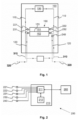
Figur 1 zeigt eine repräsentative Ansicht des Wasserheizers.figure 1 shows a representative view of the water heater. -
Figur 2 zeigt eine repräsentative Ansicht des Systems.figure 2 shows a representative view of the system.
In dieser ausführlichen Beschreibung wird ein System (200) zum Bestimmen der Restlebensdauer von Wasserheizern (100), das Gegenstand der Erfindung ist, nur anhand von nicht einschränkenden Beispielen zum besseren Verständnis des Gegenstandes beschrieben.In this detailed description, a system (200) for determining the remaining life of water heaters (100), which is the subject of the invention, is described only by way of non-limiting examples for a better understanding of the subject.
Die Erfindung betrifft ein System (200) zur Erkennung einer Verstopfung in einem Wärmetauscher (150) eines Wasserheizers (100) und damit der Restlebensdauer des Wärmetauschers (150). Wie in
Der Wasserheizer (100) umfasst eine Heizzelle (130) zur Erwärmung der Flüssigkeit in der ersten Leitung (110). Die Heizzelle (130) liefert Wärme durch den Verbrauch von Energieelementen wie Elektrizität, Gas und dergleichen. Die Heizzelle (130) kann durch thermostatähnliche Einrichtungen oder eine Steuereinheit (210) gesteuert werden. Mit anderen Worten können die Zyklen, in denen die Heizzelle (130) ein- und ausgeschaltet wird, durch diese Komponenten gesteuert werden.The water heater (100) includes a heating cell (130) for heating the liquid in the first line (110). The heater cell (130) supplies heat by consuming energy elements such as electricity, gas and the like. The heater cell (130) can be controlled by thermostat-like devices or a control unit (210). In other words, the cycles in which the heater cell (130) is turned on and off can be controlled by these components.
Der Wasserheizer (100) umfasst einen Wärmetauscher (150), um eine Wärmeübertragung zwischen der erwärmten Flüssigkeit in der ersten Leitung (110) und dem Wasser in der zweiten Leitung (120) zu gewährleisten, ohne dass diese sich miteinander vermischen. Der Wärmetauscher (150) umfasst ein erstes Volumen (151), das die Flüssigkeit in der ersten Leitung (110) aufnimmt, ein zweites Volumen (152), das die Flüssigkeit in der zweiten Leitung (120) aufnimmt, und ein Wärmeübertragungsmittel (153) zur Wärmeübertragung zwischen dem ersten Volumen (151) und dem zweiten Volumen (152). Das Wärmeübertragungselement (153) ist aus einem wärmeleitenden Material hergestellt. Der Wärmetauscher (150) kann von einem Typ sein, der im Stand der Technik als Plattentyp bekannt ist. Die Neuerung in dem erfindungsgemäßen System (200) besteht darin, eine Lebensdauer des Wärmetauschers (150) in Abhängigkeit vom Zustand der Verstopfung im zweiten Volumen (152) des Wärmetauschers (150) zu bestimmen.The water heater (100) includes a heat exchanger (150) to ensure heat transfer between the heated liquid in the first line (110) and the water in the second line (120) without mixing with each other. The heat exchanger (150) comprises a first volume (151) receiving the liquid in the first line (110), a second volume (152) receiving the liquid in the second line (120), and a heat transfer medium (153) for heat transfer between the first volume (151) and the second volume (152). The heat transfer element (153) is made of a thermally conductive material. The heat exchanger (150) may be of a type known in the art as a plate type. The innovation in the system (200) according to the invention consists in determining a lifetime of the heat exchanger (150) as a function of the state of clogging in the second volume (152) of the heat exchanger (150).
Das System (200) umfasst einen ersten Temperatursensor (221) zur Messung der Temperatur der Flüssigkeit, die in das erste Volumen (151) des Wärmetauschers (150) eintritt. Der erste Temperatursensor (221) misst die Temperatur der Flüssigkeit in der ersten Leitung (110) vor dem Eintritt in das erste Volumen (151). In einer bevorzugten Ausführungsform der Erfindung ist der erste Temperatursensor (221) am Einlass des ersten Volumens (151) vorgesehen. Das System (200) umfasst ferner einen zweiten Temperatursensor (222) zur Messung der Temperatur der aus dem ersten Volumen (151) austretenden Flüssigkeit. Der zweite Temperatursensor (222) misst die Temperatur, mit der die Flüssigkeit in der ersten Leitung (110) aus dem ersten Volumen (151) austritt. In einer bevorzugten Ausführungsform der Erfindung ist der zweite Temperatursensor (222) am Auslass des ersten Volumens (151) vorgesehen.The system (200) includes a first temperature sensor (221) for measuring the temperature of the liquid entering the first volume (151) of the heat exchanger (150). The first temperature sensor (221) measures the temperature of the liquid in the first line (110) before entering the first volume (151). In a preferred embodiment of the invention, the first temperature sensor (221) is provided at the inlet of the first volume (151). The system (200) also includes a second temperature sensor (222) for measuring the temperature of the liquid exiting the first volume (151). The second temperature sensor (222) measures the temperature at which the liquid exits the first volume (151) in the first line (110). In a preferred embodiment of the invention, the second temperature sensor (222) is provided at the outlet of the first volume (151).
Das System (200) umfasst einen dritten Temperatursensor (231) zur Messung der Temperatur der in das zweite Volumen (152) des Wärmetauschers (150) eintretenden Flüssigkeit. Der dritte Temperatursensor (231) misst die Temperatur der Flüssigkeit in der zweiten Leitung (120), bevor sie in das zweite Volumen (152) eintritt. In einer bevorzugten Ausführungsform der Erfindung ist der dritte Temperatursensor (231) am Einlass des zweiten Volumens (152) vorgesehen. Das System (200) umfasst ferner einen vierten Temperatursensor (232) zur Messung der Temperatur der aus dem zweiten Volumen (152) austretenden Flüssigkeit. Der vierte Temperatursensor (232) misst die Temperatur, mit der die Flüssigkeit in der zweiten Leitung (120) aus dem zweiten Volumen (152) austritt. In einer bevorzugten Ausführungsform der Erfindung ist der vierte Temperatursensor (232) am Auslass des zweiten Volumens (152) vorgesehen.The system (200) includes a third temperature sensor (231) for measuring the temperature of the liquid entering the second volume (152) of the heat exchanger (150). The third temperature sensor (231) measures the temperature of the liquid in the second line (120) before it enters the second volume (152). In a preferred embodiment of the invention, the third temperature sensor (231) is provided at the inlet of the second volume (152). The system (200) further includes a fourth temperature sensor (232) for measuring the temperature of the liquid exiting the second volume (152). The fourth temperature sensor (232) measures the temperature at which the liquid exits the second volume (152) in the second line (120). In a preferred embodiment of the invention, the fourth temperature sensor (232) is provided at the outlet of the second volume (152).
Das System (200) umfasst eine Durchflussmesseinrichtung (240), die in der zweiten Leitung (120) oder in der Hauswasserleitung (320) vorgesehen ist. Die Durchflussmesseinrichtung (240) misst den Massen- oder Volumenstrom der Flüssigkeit in der zweiten Leitung (120) oder in der Hauswasserleitung (320). In einer bevorzugten Ausführungsform der Erfindung misst die Durchflussmesseinrichtung (240) den Massenstrom der Flüssigkeit in der zweiten Leitung (120) oder in der Hauswasserleitung (320). In einer möglichen Ausführungsform der Erfindung misst die Durchflussmesseinrichtung (240) den Volumenstrom der Flüssigkeit in der zweiten Leitung (120) oder in der Hauswasserleitung (320). Die Durchflussmesseinrichtung (240) kann ein elektromagnetischer, ein Ultraschall-, ein Wirbel-, ein Spiral- oder ein anderer in der Technik bekannter Durchflussmesser sein.The system (200) includes a flow meter (240) which is provided in the second line (120) or in the house water line (320). The flow measuring device (240) measures the mass flow or volume flow of the liquid in the second line (120) or in the house water line (320). In a preferred embodiment of the invention, the flow measuring device (240) measures the mass flow of the liquid in the second line (120) or in the domestic water line (320). In a possible embodiment of the invention the flow measuring device (240) measures the volume flow of the liquid in the second line (120) or in the domestic water line (320). The flow meter (240) may be an electromagnetic, ultrasonic, vortex, spiral or other flow meter known in the art.
Das System (200) umfasst eine Steuereinheit (210), die die Temperatur- und Durchflussmessungen empfängt. Die Steuereinheit (210) umfasst eine Prozessoreinheit (211) zum Empfang von Temperatur- und Durchflussmessungen von einem ersten Temperatursensor (221), einem zweiten Temperatursensor (222), einem dritten Temperatursensor (231), einem vierten Temperatursensor (232) und einer Durchflussmesseinrichtung (240). Die Steuereinheit (210) umfasst eine Speichereinheit (212), die der Prozessoreinheit (211) derart zugeordnet ist, dass die Prozessoreinheit (211) Daten lesen und Daten aufzeichnen kann. Die genannte Prozessoreinheit (211) kann ein Mikroprozessor sein, auf dem Softwarecodes ausgeführt werden. Die Steuereinheit (210) speichert die empfangenen Temperatur- und Durchflussmessungen in der Speichereinheit (212) indem sie diese ihren Empfangszeiten zuordnet. Die Steuereinheit (210) bestimmt eine Wärmeübertragungsrate des zweiten Volumens (152) gemäß den von dem dritten Temperatursensor (231), dem vierten Temperatursensor (232) und der Durchflussmesseinrichtung (240) empfangenen Messungen und gemäß einem spezifischen Wärmewert. Der hier genannte spezifische Wärmewert bezieht sich auf die Menge an Wärmeenergie, die für einen Temperaturanstieg einer Masseneinheit der in der Hauswasserleitung (320) oder in der zweiten Leitung (120) zirkulierenden Flüssigkeit erforderlich ist. Die Steuereinheit (210) bestimmt eine logarithmische mittlere Temperaturdifferenz für den Wärmetauscher (150) gemäß den vom ersten Temperatursensor (221), dem zweiten Temperatursensor (222), dem dritten Temperatursensor (231) und dem vierten Temperatursensor (232) empfangenen Messungen. Die genannte logarithmische mittlere Temperaturdifferenz ist ein Mittelwert der Temperaturänderungen im ersten Volumen (151) und im zweiten Volumen (152) des Wärmetauschers (150) gemäß den von den Temperatursensoren empfangenen Messungen. Die Steuereinheit (210) bestimmt einen Wärmeübertragungskoeffizienten gemäß der logarithmischen mittleren Temperaturdifferenz und der Wärmeübertragungsrate, die in Abhängigkeit von der Wärmeübertragungsfläche des Wärmetauschers (150) berechnet wird. Die Wärmeübertragungsfläche bezieht sich auf die Oberfläche des Wärmeübertragungselements (153), das zwischen dem ersten Volumen (151) und dem zweiten Volumen (152) vorgesehen ist. Die Steuereinheit (210) berechnet periodisch den Wärmeübertragungskoeffizienten und speichert diesen in der Speichereinheit (212).The system (200) includes a control unit (210) that receives the temperature and flow measurements. The control unit (210) comprises a processor unit (211) for receiving temperature and flow measurements from a first temperature sensor (221), a second temperature sensor (222), a third temperature sensor (231), a fourth temperature sensor (232) and a flow measuring device ( 240). The control unit (210) comprises a memory unit (212) which is assigned to the processor unit (211) in such a way that the processor unit (211) can read data and record data. Said processor unit (211) may be a microprocessor on which software codes are executed. The control unit (210) stores the received temperature and flow measurements in the memory unit (212) by associating them with their times of reception. The control unit (210) determines a heat transfer rate of the second volume (152) according to the measurements received from the third temperature sensor (231), the fourth temperature sensor (232) and the flow meter (240) and according to a specific calorific value. The specific calorific value referred to here refers to the amount of thermal energy required for a temperature increase of a unit mass of the liquid circulating in the domestic water line (320) or in the second line (120). The control unit (210) determines a logarithmic mean temperature difference for the heat exchanger (150) according to the measurements received from the first temperature sensor (221), the second temperature sensor (222), the third temperature sensor (231) and the fourth temperature sensor (232). Said logarithmic mean temperature difference is an average of the temperature changes in the first volume (151) and in the second volume (152) of the heat exchanger (150) according to the measurements received from the temperature sensors. The control unit (210) determines a heat transfer coefficient according to the logarithmic mean temperature difference and the heat transfer rate calculated depending on the heat transfer area of the heat exchanger (150). The heat transfer area refers to the surface area of the heat transfer element (153) provided between the first volume (151) and the second volume (152). The control unit (210) periodically calculates the heat transfer coefficient and stores it in the storage unit (212).
Das System (200) umfasst eine Benutzerschnittstelle (260), über die ein Benutzer die von der Steuereinheit (210) empfangenen Messungen oder berechneten Werte nachverfolgen kann. Die Steuereinheit (210) überwacht den Wärmeübertragungskoeffizienten auf der Benutzerschnittstelle (260). Die Benutzerschnittstelle (260) kann auf dem Wasserheizer (100) angeordnet sein. In einer möglichen Ausführungsform kann sich die Benutzerschnittstelle (260) in einem vom Wasserheizer (100) entfernten Raum befinden und einen drahtgebundenen oder drahtlosen Datenaustausch mit der Steuereinheit (210) ermöglichen.The system (200) includes a user interface (260) through which a user can track the measurements or calculated values received from the control unit (210). The controller (210) monitors the heat transfer coefficient on the user interface (260). The user interface (260) can be located on the water heater (100). In one possible embodiment, the user interface (260) can be located in a room remote from the water heater (100) and enable wired or wireless communication with the control unit (210).
Die Steuereinheit (210) bestimmt eine Lebensdauer, wenn der Wärmeübertragungskoeffizient einen ersten Schwellenwert überschreitet. Diese Lebensdauer wird auf der Grundlage der gespeicherten Wärmeübertragungskoeffizienten mit Hilfe eines Alterungsmodells berechnet. Die Lebensdauer bezieht sich auf die Restlebensdauer des Wärmetauschers (150), nachdem der Wärmeübertragungskoeffizient einen zweiten Schwellenwert überschritten hat. Die hier genannte Lebensdauer bezieht sich auf die geschätzte Restbetriebsdauer des Wärmetauschers (150), ohne dass ein bestimmter Wirkungsgrad unterschritten wird. Wenn der Wärmetauscher (150) den genannten Wirkungsgrad unterschreitet, kann keine ausreichende Wärmeübertragung zwischen dem ersten Volumen (151) und dem zweiten Volumen (152) gewährleistet werden und es wird mehr Energie als nötig verbraucht. Das erwähnte Alterungsmodell ist ein Software-Algorithmus. Das Alterungsmodell ist ein stochastisches maschinelles Lernmodell, das mit gespeicherten Wärmeübertragungskoeffizienten trainiert wird. Dementsprechend bestimmt die Steuereinheit (210) das Alterungsmodell des Wärmetauschers (150) auf der Grundlage der vorherigen Wärmeübertragungskoeffizienten. Als nicht einschränkendes Beispiel kann die Feststellung einer Abnahme des Wärmeübertragungskoeffizienten auf eine Verstopfung im Wärmetauscher (150) hinweisen. Hier zeigt das mit den gespeicherten Wärmeübertragungskoeffizienten trainierte Alterungsmodell einen Abnahmetrend des Wärmeübertragungskoeffizienten. Wenn der Wärmeübertragungskoeffizient einen ersten Schwellenwert überschreitet, kann dementsprechend die Restlebensdauer des Wärmetauschers (150) als Ergebnis der Überschreitung eines zweiten Schwellenwertes berechnet werden.The controller (210) determines a lifetime when the heat transfer coefficient exceeds a first threshold. This lifetime is calculated based on the stored heat transfer coefficients using an aging model. Life refers to the remaining life of the heat exchanger (150) after the heat transfer coefficient has exceeded a second threshold. The service life mentioned here refers to the estimated remaining service life of the heat exchanger (150) without falling below a certain level of efficiency. If the heat exchanger (150) falls below the stated efficiency, sufficient heat transfer between the first volume (151) and the second volume (152) cannot be guaranteed and more energy than necessary is consumed. The aging model mentioned is a software algorithm. The aging model is a stochastic machine learning model trained with stored heat transfer coefficients. Accordingly, the controller (210) determines the aging model of the heat exchanger (150) based on the previous heat transfer coefficients. As a non-limiting example, the detection of a decrease in the heat transfer coefficient may indicate a clogging in the heat exchanger (150). Here, the aging model trained with the stored heat transfer coefficients shows a decreasing trend in the heat transfer coefficient. Accordingly, if the heat transfer coefficient exceeds a first threshold, the remaining life of the heat exchanger (150) may be calculated as a result of exceeding a second threshold.
Die Steuereinheit (210) ist so konfiguriert, dass sie ein Warnsignal erzeugt, wenn die Lebensdauer einen ersten Lebensdauerschwellenwert überschreitet. Der erste Lebensdauerschwellenwert bezieht sich auf eine bestimmte Zeitspanne. Der erste Lebensdauerschwellenwert kann während der Produktion oder durch den Benutzer festgelegt werden. Wenn der erste Lebensdauerschwellenwert beispielsweise auf 90 Tage eingestellt ist, erzeugt die Steuereinheit (210) das Warnsignal, wenn die Lebensdauer unter 90 Tage fällt.The controller (210) is configured to generate a warning signal when the lifetime exceeds a first lifetime threshold. The first lifetime threshold is related to a specific period of time. The first lifetime threshold can be set during production or by the user. For example, if the first lifespan threshold is set to 90 days, the controller (210) generates the warning signal when the lifespan falls below 90 days.
In einer möglichen Ausführungsform wird das Warnsignal von der Steuereinheit (210) auf der Benutzerschnittstelle (260) überwacht. In einer möglichen Ausführungsform der Erfindung kann ein zweiter Lebensdauerschwellenwert bestimmt werden. Wenn der zweite Lebensdauerschwellenwert überschritten wird, kann die Steuereinheit (210) den Betrieb des Wasserheizers (100) stoppen.In one possible embodiment, the warning signal is monitored by the control unit (210) on the user interface (260). In a possible embodiment of the invention, a second lifetime threshold can be determined. If the second lifetime threshold is exceeded, the controller (210) may stop operation of the water heater (100).
Die Steuereinheit (210) empfängt die Temperatur- und Durchflussmessungen in Echtzeit. Die Prozessoreinheit (211) verarbeitet die empfangenen Messwerte kontinuierlich. Die Wärmeübertragungsrate wird nach der folgenden Formel (1) berechnet. ![]()
![]()
Dabei ist "QCH " die Wärmeübertragungsrate in der Hauswasserleitung (320); "mCH" ist der Massenstrom in der Hauswasserleitung (320); "Cp,CH", ist der spezifische Wärmewert der Flüssigkeit in der zweiten Leitung (120); "ΔTCH " ist die Temperaturdifferenz der Flüssigkeit am Einlass und Auslass des zweiten Volumens (152).Where " Q CH " is the heat transfer rate in the domestic water line (320); " m CH" is the mass flow in the domestic water line (320); " Cp , CH " is the specific heat of the liquid in the second conduit (120); "Δ T CH " is the liquid temperature difference at the inlet and outlet of the second volume (152).
Die logarithmische mittlere Temperaturdifferenz wird nach der folgenden Formel (2) berechnet. 
Dabei steht "LMTD" für die logarithmische mittlere Temperaturdifferenz; "T" steht für die Temperatur; "CH" steht für den Zentralheizkreislauf (310); "DHW" steht für die Hauswasserleitung (320); "inlet" steht für den Einlass; "outlet" steht für den Auslass."LMTD" stands for the logarithmic mean temperature difference; "T" stands for temperature; "CH" stands for the central heating circuit (310); "DHW" stands for the domestic water line (320); "inlet" stands for the inlet; "outlet" stands for the outlet.
Der Wärmeübertragungskoeffizient wird nach der folgenden Formel (3) berechnet. 
Dabei ist "U" der Wärmeübertragungskoeffizient; "QCH " die Wärmeübertragungsrate in der Hauswasserleitung (320); "A" die Wärmeübertragungsfläche des Wärmeübertragungselements (153); "LMTD" die logarithmische mittlere Temperaturdifferenz.where "U" is the heat transfer coefficient; " Q CH " the heat transfer rate in the domestic water line (320); "A" the heat transfer area of the heat transfer element (153); "LMTD" the logarithmic mean temperature difference.
In einer beispielhaften Ausführungsform wird eine Lebensdauerberechnung durchgeführt, wenn der Wärmeübertragungskoeffizient einen ersten Schwellenwert überschreitet. Der Hauptzweck der Verwendung des ersten Schwellenwerts besteht darin, der Prozessoreinheit (211) Zeit zu geben, um genügend Daten zu erhalten. Die Lebensdauer bezieht sich auf die geschätzte Restlebensdauer des Wärmetauschers (150), die verbleibt, nachdem der Wärmeübertragungskoeffizient einen zweiten Schwellenwert überschritten hat.In an exemplary embodiment, a lifetime calculation is performed when the heat transfer coefficient exceeds a first threshold. The main purpose of using the first threshold is to give the processing unit (211) time to get enough data. The lifetime refers to the estimated remaining lifetime of the heat exchanger (150) after the heat transfer coefficient has exceeded a second threshold.
Der Schutzumfang der Erfindung ist in den Ansprüchen in der Anlage angegeben und kann nicht auf das beschränkt werden, was in dieser detaillierten Beschreibung zum Zweck der Angabe von Beispielen erläutert wird. Es ist offensichtlich, dass der Fachmann auf dem technischen Gebiet im Lichte der obigen Erläuterungen ähnliche Ausführungsformen erstellen kann.The scope of the invention is indicated in the appended claims and should not be limited to what is explained in this detailed description for the purpose of giving examples. It is obvious that the person skilled in the technical field can create similar embodiments in the light of the above explanations.
- 100 Wasserheizer100 water heaters
- 110 Erste Leitung110 First line
- 120 Zweite Leitung120 second line
- 130 Heizzelle130 heater cell
- 150 Wärmetauscher150 heat exchangers
- 151 Erstes Volumen151 First volume
- 152 Zweites Volumen152 Second Volume
- 153 Wärmeübertragungselement153 heat transfer element
- 200 System200 systems
- 210 Steuereinheit210 control unit
- 211 Prozessoreinheit211 processor unit
- 212 Speichereinheit212 storage unit
- 221 Erster Temperatursensor221 First temperature sensor
- 222 Zweiter Temperatursensor222 Second temperature sensor
- 231 Dritter Temperatursensor231 Third temperature sensor
- 232 Vierter Temperatursensor232 Fourth temperature sensor
- 240 Durchflussmesseinrichtung240 flow meter
- 260 Benutzerschnittstelle260 user interface
- 310 Zentralheizkreislauf310 central heating circuit
- 320 Hauswasserleitung320 domestic water pipe
Claims (11)
wobei die Steuereinheit so konfiguriert ist, dass sie folgende Verfahrensschritte ausführt:
wherein the control unit is configured to perform the following method steps:
Applications Claiming Priority (1)
| Application Number | Priority Date | Filing Date | Title |
|---|---|---|---|
| TR202121681 | 2021-12-29 |
Publications (1)
| Publication Number | Publication Date |
|---|---|
| EP4206554A1 true EP4206554A1 (en) | 2023-07-05 |
Family
ID=85285348
Family Applications (1)
| Application Number | Title | Priority Date | Filing Date |
|---|---|---|---|
| EP22214819.9A Pending EP4206554A1 (en) | 2021-12-29 | 2022-12-20 | System for determining the remaining service life of the heat exchanger of water heaters |
Country Status (1)
| Country | Link |
|---|---|
| EP (1) | EP4206554A1 (en) |
Citations (7)
| Publication number | Priority date | Publication date | Assignee | Title |
|---|---|---|---|---|
| EP0155826A2 (en) * | 1984-03-23 | 1985-09-25 | International Control Automation Finance S.A. | Heat exchanger performance monitors |
| WO2007031087A1 (en) * | 2005-09-15 | 2007-03-22 | Danfoss A/S | Heat exchanger and method for regulating a heat exchanger |
| DE102009042994A1 (en) | 2009-09-25 | 2011-03-31 | Linde Aktiengesellschaft | Method for monitoring operation of e.g. plate-type heat exchanger in chemical plant to control safety precautions, involves providing circuit e.g. valves, to control volumetric flow of fluid streams into apparatus depending on comparison |
| EP2392982A2 (en) * | 2006-09-28 | 2011-12-07 | Fisher-Rosemount Systems, Inc. | Abnormal situation prevention in a heat exchanger |
| EP2908059A1 (en) * | 2014-02-12 | 2015-08-19 | Robert Bosch Gmbh | Method for the diagnosis of a heating installation with at least one heat exchanger |
| JP2020176729A (en) * | 2019-04-15 | 2020-10-29 | リンナイ株式会社 | Heat source device |
| EP3901550A1 (en) * | 2020-04-19 | 2021-10-27 | Bosch Termoteknik Isitmave Klima Sanayi Ticaret Anonim Sirketi | A system for detecting clogging in a heat exchanger |
-
2022
- 2022-12-20 EP EP22214819.9A patent/EP4206554A1/en active Pending
Patent Citations (7)
| Publication number | Priority date | Publication date | Assignee | Title |
|---|---|---|---|---|
| EP0155826A2 (en) * | 1984-03-23 | 1985-09-25 | International Control Automation Finance S.A. | Heat exchanger performance monitors |
| WO2007031087A1 (en) * | 2005-09-15 | 2007-03-22 | Danfoss A/S | Heat exchanger and method for regulating a heat exchanger |
| EP2392982A2 (en) * | 2006-09-28 | 2011-12-07 | Fisher-Rosemount Systems, Inc. | Abnormal situation prevention in a heat exchanger |
| DE102009042994A1 (en) | 2009-09-25 | 2011-03-31 | Linde Aktiengesellschaft | Method for monitoring operation of e.g. plate-type heat exchanger in chemical plant to control safety precautions, involves providing circuit e.g. valves, to control volumetric flow of fluid streams into apparatus depending on comparison |
| EP2908059A1 (en) * | 2014-02-12 | 2015-08-19 | Robert Bosch Gmbh | Method for the diagnosis of a heating installation with at least one heat exchanger |
| JP2020176729A (en) * | 2019-04-15 | 2020-10-29 | リンナイ株式会社 | Heat source device |
| EP3901550A1 (en) * | 2020-04-19 | 2021-10-27 | Bosch Termoteknik Isitmave Klima Sanayi Ticaret Anonim Sirketi | A system for detecting clogging in a heat exchanger |
Similar Documents
| Publication | Publication Date | Title |
|---|---|---|
| EP1936290B1 (en) | Method and device for detecting the hydraulic state of a heating system | |
| EP2753999A1 (en) | Method for operating and/or monitoring an hvac system | |
| DE102007014810B3 (en) | Energy meter e.g. heat and cold meter, for e.g. heater, has main data memory for depositing orderly detected heat and cool quantity, and auxiliary data memories depositing disorderly detected heat and cool quantities | |
| EP3217157B1 (en) | Heat cost allocator and method for measuring the heat loss of a radiator | |
| DE102007055132A1 (en) | Monitoring and diagnosis armature for warm water, has electronic module adjusting signals in compare to preset limited values and sending optical and/or acoustic and/or electronic warning message during exceeding of limiting values | |
| EP3901550B1 (en) | A system for detecting clogging in a heat exchanger | |
| AT13029U1 (en) | CONNECTION DEVICE FOR CONNECTING A HEAT SOURCE TO A HEAT PUMP CIRCUIT | |
| DE102004021423A1 (en) | Method and device for determining the efficiency of a heat exchanger | |
| EP3220065B1 (en) | Method and control device for increasing the performance ratio of a heat generator in a heating installation | |
| WO2006084656A1 (en) | Method and device for detecting the energy and media consumption and the user-specific allocation in common ventilation and air conditioning systems | |
| EP2775370A2 (en) | Device for heating rooms, comprising at least one central heat source and comprising the heating circuits allocated to the rooms | |
| EP4206554A1 (en) | System for determining the remaining service life of the heat exchanger of water heaters | |
| WO2023126244A1 (en) | System for determining the remaining service life of the heat exchanger of water heaters | |
| EP3896360B1 (en) | A system for detecting clogging in a heat exchanger | |
| EP2327971B1 (en) | Method for analysing the heat volume distribution in a heating system and device for executing the method | |
| EP4015977B1 (en) | System and method for unclogging the water heater | |
| EP4015919A1 (en) | System for detecting clogging in the central heating circuit | |
| EP2392867A2 (en) | Information system based on a heating system with local supply pumps and method for using the information system | |
| DE102017112505A1 (en) | Method for operating a thermal consumption system | |
| EP1154205B1 (en) | Heat transport system with heat production installation having flow rate control | |
| EP3220066B1 (en) | Method and controller for incresing the degree of utilisation of a heat generator within a heating system | |
| DE102015109957B4 (en) | Flow water meters | |
| DE102021203000B4 (en) | Method for operating a heat cost allocator and heat cost allocator | |
| DE102016225408A1 (en) | Fluid device and method for monitoring a fluid device | |
| DE102010052104A1 (en) | Heat meter for use in district heating plant for built in domestic supply line for determining consumed heat quantity, has temperature sensor switched on so that temperature in return line of primary circuit is involved in evaluation |
Legal Events
| Date | Code | Title | Description |
|---|---|---|---|
| PUAI | Public reference made under article 153(3) epc to a published international application that has entered the european phase |
Free format text: ORIGINAL CODE: 0009012 |
|
| STAA | Information on the status of an ep patent application or granted ep patent |
Free format text: STATUS: THE APPLICATION HAS BEEN PUBLISHED |
|
| AK | Designated contracting states |
Kind code of ref document: A1 Designated state(s): AL AT BE BG CH CY CZ DE DK EE ES FI FR GB GR HR HU IE IS IT LI LT LU LV MC ME MK MT NL NO PL PT RO RS SE SI SK SM TR |
|
| STAA | Information on the status of an ep patent application or granted ep patent |
Free format text: STATUS: REQUEST FOR EXAMINATION WAS MADE |
|
| 17P | Request for examination filed |
Effective date: 20240105 |
|
| RBV | Designated contracting states (corrected) |
Designated state(s): AL AT BE BG CH CY CZ DE DK EE ES FI FR GB GR HR HU IE IS IT LI LT LU LV MC ME MK MT NL NO PL PT RO RS SE SI SK SM TR |