EP2908059A1 - Method for the diagnosis of a heating installation with at least one heat exchanger - Google Patents
Method for the diagnosis of a heating installation with at least one heat exchanger Download PDFInfo
- Publication number
- EP2908059A1 EP2908059A1 EP15151896.6A EP15151896A EP2908059A1 EP 2908059 A1 EP2908059 A1 EP 2908059A1 EP 15151896 A EP15151896 A EP 15151896A EP 2908059 A1 EP2908059 A1 EP 2908059A1
- Authority
- EP
- European Patent Office
- Prior art keywords
- heat exchanger
- threshold
- temperature
- fluid
- temperature difference
- Prior art date
- Legal status (The legal status is an assumption and is not a legal conclusion. Google has not performed a legal analysis and makes no representation as to the accuracy of the status listed.)
- Granted
Links
- 238000000034 method Methods 0.000 title claims abstract description 41
- 238000010438 heat treatment Methods 0.000 title claims abstract description 36
- 238000003745 diagnosis Methods 0.000 title claims abstract description 16
- 238000009434 installation Methods 0.000 title 1
- 239000012530 fluid Substances 0.000 claims abstract description 39
- 238000012546 transfer Methods 0.000 claims description 27
- 238000011109 contamination Methods 0.000 claims description 4
- 239000008236 heating water Substances 0.000 description 9
- 238000012423 maintenance Methods 0.000 description 8
- XLYOFNOQVPJJNP-UHFFFAOYSA-N water Substances O XLYOFNOQVPJJNP-UHFFFAOYSA-N 0.000 description 8
- 238000005259 measurement Methods 0.000 description 5
- 230000001105 regulatory effect Effects 0.000 description 5
- 238000004140 cleaning Methods 0.000 description 4
- 238000004393 prognosis Methods 0.000 description 3
- 230000007423 decrease Effects 0.000 description 2
- 230000001419 dependent effect Effects 0.000 description 2
- 230000007257 malfunction Effects 0.000 description 2
- 239000000203 mixture Substances 0.000 description 2
- 239000000126 substance Substances 0.000 description 2
- 208000027418 Wounds and injury Diseases 0.000 description 1
- 238000009825 accumulation Methods 0.000 description 1
- 230000032683 aging Effects 0.000 description 1
- 230000006378 damage Effects 0.000 description 1
- 230000003247 decreasing effect Effects 0.000 description 1
- 230000009969 flowable effect Effects 0.000 description 1
- 230000006870 function Effects 0.000 description 1
- 208000014674 injury Diseases 0.000 description 1
- 230000009191 jumping Effects 0.000 description 1
- 239000007788 liquid Substances 0.000 description 1
- COCAUCFPFHUGAA-MGNBDDOMSA-N n-[3-[(1s,7s)-5-amino-4-thia-6-azabicyclo[5.1.0]oct-5-en-7-yl]-4-fluorophenyl]-5-chloropyridine-2-carboxamide Chemical compound C=1C=C(F)C([C@@]23N=C(SCC[C@@H]2C3)N)=CC=1NC(=O)C1=CC=C(Cl)C=N1 COCAUCFPFHUGAA-MGNBDDOMSA-N 0.000 description 1
- 238000012545 processing Methods 0.000 description 1
- 230000000717 retained effect Effects 0.000 description 1
- 239000007787 solid Substances 0.000 description 1
Images
Classifications
-
- F—MECHANICAL ENGINEERING; LIGHTING; HEATING; WEAPONS; BLASTING
- F24—HEATING; RANGES; VENTILATING
- F24D—DOMESTIC- OR SPACE-HEATING SYSTEMS, e.g. CENTRAL HEATING SYSTEMS; DOMESTIC HOT-WATER SUPPLY SYSTEMS; ELEMENTS OR COMPONENTS THEREFOR
- F24D19/00—Details
- F24D19/0092—Devices for preventing or removing corrosion, slime or scale
-
- F—MECHANICAL ENGINEERING; LIGHTING; HEATING; WEAPONS; BLASTING
- F24—HEATING; RANGES; VENTILATING
- F24D—DOMESTIC- OR SPACE-HEATING SYSTEMS, e.g. CENTRAL HEATING SYSTEMS; DOMESTIC HOT-WATER SUPPLY SYSTEMS; ELEMENTS OR COMPONENTS THEREFOR
- F24D19/00—Details
- F24D19/10—Arrangement or mounting of control or safety devices
- F24D19/1006—Arrangement or mounting of control or safety devices for water heating systems
- F24D19/1066—Arrangement or mounting of control or safety devices for water heating systems for the combination of central heating and domestic hot water
-
- F—MECHANICAL ENGINEERING; LIGHTING; HEATING; WEAPONS; BLASTING
- F24—HEATING; RANGES; VENTILATING
- F24H—FLUID HEATERS, e.g. WATER OR AIR HEATERS, HAVING HEAT-GENERATING MEANS, e.g. HEAT PUMPS, IN GENERAL
- F24H15/00—Control of fluid heaters
- F24H15/10—Control of fluid heaters characterised by the purpose of the control
- F24H15/104—Inspection; Diagnosis; Trial operation
-
- F—MECHANICAL ENGINEERING; LIGHTING; HEATING; WEAPONS; BLASTING
- F24—HEATING; RANGES; VENTILATING
- F24H—FLUID HEATERS, e.g. WATER OR AIR HEATERS, HAVING HEAT-GENERATING MEANS, e.g. HEAT PUMPS, IN GENERAL
- F24H15/00—Control of fluid heaters
- F24H15/20—Control of fluid heaters characterised by control inputs
- F24H15/212—Temperature of the water
- F24H15/215—Temperature of the water before heating
-
- F—MECHANICAL ENGINEERING; LIGHTING; HEATING; WEAPONS; BLASTING
- F24—HEATING; RANGES; VENTILATING
- F24H—FLUID HEATERS, e.g. WATER OR AIR HEATERS, HAVING HEAT-GENERATING MEANS, e.g. HEAT PUMPS, IN GENERAL
- F24H15/00—Control of fluid heaters
- F24H15/20—Control of fluid heaters characterised by control inputs
- F24H15/212—Temperature of the water
- F24H15/219—Temperature of the water after heating
-
- F—MECHANICAL ENGINEERING; LIGHTING; HEATING; WEAPONS; BLASTING
- F24—HEATING; RANGES; VENTILATING
- F24H—FLUID HEATERS, e.g. WATER OR AIR HEATERS, HAVING HEAT-GENERATING MEANS, e.g. HEAT PUMPS, IN GENERAL
- F24H15/00—Control of fluid heaters
- F24H15/20—Control of fluid heaters characterised by control inputs
- F24H15/269—Time, e.g. hour or date
-
- F—MECHANICAL ENGINEERING; LIGHTING; HEATING; WEAPONS; BLASTING
- F24—HEATING; RANGES; VENTILATING
- F24H—FLUID HEATERS, e.g. WATER OR AIR HEATERS, HAVING HEAT-GENERATING MEANS, e.g. HEAT PUMPS, IN GENERAL
- F24H15/00—Control of fluid heaters
- F24H15/20—Control of fluid heaters characterised by control inputs
- F24H15/281—Input from user
-
- F—MECHANICAL ENGINEERING; LIGHTING; HEATING; WEAPONS; BLASTING
- F24—HEATING; RANGES; VENTILATING
- F24H—FLUID HEATERS, e.g. WATER OR AIR HEATERS, HAVING HEAT-GENERATING MEANS, e.g. HEAT PUMPS, IN GENERAL
- F24H1/00—Water heaters, e.g. boilers, continuous-flow heaters or water-storage heaters
- F24H1/48—Water heaters for central heating incorporating heaters for domestic water
- F24H1/52—Water heaters for central heating incorporating heaters for domestic water incorporating heat exchangers for domestic water
-
- F—MECHANICAL ENGINEERING; LIGHTING; HEATING; WEAPONS; BLASTING
- F24—HEATING; RANGES; VENTILATING
- F24H—FLUID HEATERS, e.g. WATER OR AIR HEATERS, HAVING HEAT-GENERATING MEANS, e.g. HEAT PUMPS, IN GENERAL
- F24H15/00—Control of fluid heaters
- F24H15/30—Control of fluid heaters characterised by control outputs; characterised by the components to be controlled
- F24H15/395—Information to users, e.g. alarms
Definitions
- the invention relates to a method for the diagnosis of a heating system with at least one heatable heat exchanger, which is flowed through by a fluid to be heated.
- the invention also relates to a heating system in which the method for diagnosis runs.
- Heat exchangers are used wherever a cold medium, such as water, is to be heated by heat transfer. With increasing use and aging of the heat exchanger decreases its heat transfer performance, for example due to pollution. Therefore, a heat exchanger must be cleaned at regular intervals.
- the method is characterized in that a message is issued and / or is stored when heating of the fluid by a certain or determinable temperature takes longer than a predetermined or predeterminable time and / or when the heating by the heat exchanger of a certain or determinable mass flow of the fluid remains below a predetermined or predeterminable temperature difference.
- a fluid is defined as a flowable substance which can absorb, store and release heat, such as a gas or a liquid.
- solid substances are also conceivable which can store and release heat.
- the term fluid is used here, it is meant in general heat transfer media that can be used in a heating system.
- a heat exchanger is understood to mean a device for transferring heat to a fluid.
- the term heat exchanger is also used synonymously.
- the time for heating the fluid by a certain or determinable temperature is also abbreviated as the warm-up time.
- one or more parameters are determined and / or stored, such as the time for heating the fluid by a certain or determinable temperature, that is, the warm-up time, and / or a heat transfer coefficient of the heat exchanger and / or a temperature difference between a flow and return temperature of the heat exchanger, which has the advantage that this information can be used for diagnostic and / or prognostic purposes, for example, with respect to the state of the heat exchanger. It is advantageous if a message, in particular about a reduced functionality of the heat exchanger, in particular due to contamination, issued and / or stored as soon as the number of cases in which the parameter or reaches a certain or determinable threshold, a certain or determinable value exceeds. Such a hysteresis has the further advantage that a message is not issued immediately at the first occurrence of such a case, but that the accumulation of occurring cases can be regarded as a reliable indication.
- a power of a pump in a first Operarounik can be used as an indicator. If, for example, a higher power of the pump is required in the course of time, with a constant or even decreasing temperature difference, this indicates a reduced functionality.
- the flow temperature in particular via a first sensor in the flow of the first GeneralMap Vietnamese Republic of China
- the return temperature in particular via a second sensor in the return of the first Generalost Vietnamese Republic of China
- At least one threshold value for the parameter or parameters is specified and / or calculated, if they have not yet been determined. Also, at least one value each is given as an upper bound for the number of cases in which the parameter (s) reach the associated threshold, if it has not yet been determined.
- the parameter (s), the respectively associated threshold value and / or the respectively associated value for the number of cases in which the respective threshold value is reached are recorded and / or output and / or can be read out.
- a counter is initiated as soon as the threshold is reached for the first time, and the counter is incremented as the parameter (s) reach the respective threshold once more.
- the counter is also initiated or incremented if the threshold is undershot or exceeded.
- the counter can be recorded and / or output and / or read out.
- the threshold value for the heat transfer coefficient can be calculated, which has the advantage that an accurate, theoretical value can be used as the reference value.
- c the heat capacity of the fluid
- ⁇ T threshold the temperature difference, for example between the heat exchanger and the fluid or the temperature difference between flow temperature and return temperature
- m is the mass flow of the fluid
- A is the free heat transfer area
- .DELTA.T Threshold is the average logarithmic temperature difference associated with ⁇ T Threshold , which is calculated from inlet temperatures into the heat exchanger and outlet temperatures from the heat exchanger.
- the invention also relates to a heating system with at least one heatable heat exchanger through which a fluid to be heated flows, in which the above-described method for diagnosis runs.
- a message is issued and / or stored when a heating of the fluid by a certain or determinable temperature longer than a predetermined or predeterminable time needed and / or if the heating by the Heat exchanger of a certain or determinable mass flow of the fluid remains below a predetermined or predeterminable temperature difference.
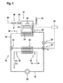
- FIG. 1 shows a heating system 10 with a heat generator 12, which is provided with a heat exchanger 14.
- a fluid such as heating water
- a second Operawit Vietnamese Republic 16 is used to heat cold hot water by means of a heat exchanger 20, for example in the continuous flow principle.
- the first Generalising réelle 16 has a pump 22 and a three-way valve 24 and a three-way valve 25 to ensure the circulation of the fluid.
- At least one heat consumer 25 is supplied with warm heating water.
- a sensor 26 in particular a temperature sensor, for measuring the flow temperature.
- a sensor 28 for measuring the return temperature.
- a sensor 30 measures the temperature of the cold water Entry through the heat exchanger 20
- a sensor 32 measures the temperature of the heated cold water after leaving.
- the heat generator 12 may be a variety of heaters that operate on fossil or renewable resources.
- the heat generator 12 with the aid of a blower 34 via a line 36, a gas-air mixture is supplied.
- this line 36 is still a valve 38.
- Exhaust products are passed through an exhaust pipe 40 to the outside.
- a flame generated by the gas burner 33 the fluid which circulates through the heat exchanger 14 is heated.
- the heating system 10 further includes a display 42 and a control and / or regulating unit 44, wherein it is located outside of the heat generator 12.
- the display 42 is attached to the heat generator 12.
- the heat generator 12, the control and / or regulating unit 44 and the display 42 are connected to each other and can communicate with each other.
- the heat generator 12 via the control and / or regulating unit 44 is still connected to the heat consumer 25 and other control or regulating elements, such as the pump 22, the valves 23, 24, the blower 34, the valve 38 and / or with a room thermostat to ensure an even more optimized and flawless process.
- Conceivable in this case is a wired or a wireless connection, as well as a mixture of these types of connections.
- control and / or regulating unit 44 may also be located within the heat generator 12.
- Other embodiments are also conceivable. The same applies to the display 42.
- the time for heating the fluid through the heat exchanger 14, 20, called warm-up time briefly, its heat transfer coefficient and the temperature difference between flow and return temperature of the heat exchanger 14, 20 are system inherent parameters and are used according to the invention as indicators of reduced efficiency of the heat exchanger 14, 20, especially due to pollution, used.
- the heat transfer coefficient decreases with increasing resistance of the heat exchanger 14, 20, which is the case, for example, precisely when the surface of the heat exchanger 14, 20 is increasingly polluted.
- the performance of the heat exchanger 14, 20, which leads to a higher warm-up time on the other hand, if one specifies a fixed duration, to a lower temperature difference after this time has expired.
- the determination of the warm-up time is dependent on the burner start.
- the time measurement starts at burner start and ends as soon as a setpoint temperature for the fluid, for example for the service water or heating water, has been reached.
- the core of the method is the output of a message when a heating of the fluid by a certain or determinable temperature longer than a predetermined or predeterminable time needed or if the heating by the heat exchanger 14, 20 of a certain or determinable mass flow of the fluid below a predetermined or predeterminable Temperature difference remains. Both cases can occur.
- the message is saved for later purposes, such as for a prognosis or diagnosis, so that it is retrievable at any time.
- the method is applicable in principle to any heat exchanger. In the following, it will be explained with reference to the heat exchanger 14.
- the user enters the parameter (s) to be diagnosed. He can make a diagnosis based on the warm-up time, the heat transfer coefficient or select the temperature difference between flow and return temperatures. It is also possible to select several modes at the same time, which are then executed in parallel or serially. In the following, the case is considered that all modes are selected and executed in parallel.
- step 52 the flow temperature via the sensor 26 and the return temperature via the sensor 28 are measured. Further, a target value for a temperature of the fluid, such as a target value for the temperature of the heating water and the service water, set.
- the values necessary for the method are specified or calculated, if they are not yet present.
- the values can be specified for the same systems. For example, they can be set as defaults that are used automatically or chosen by the user. They can also be entered by the user. For new or maintained systems, the values can be reset or recalculated.
- a threshold 56 is set or calculated in step 53. Further, a value or a maximum number 58 may be determined, which represents an upper bound for the number of cases in which the warm-up time reaches or exceeds the threshold 56. If the maximum number 58 is 20, for example, a message is issued when the 21st case of an increased warm-up time occurs. Threshold 56 is present in the system as a default or can be changed or specified by the user.
- a threshold value 60 k threshold is set or calculated in step 54.
- ideal heat transfer conditions of the heat exchanger 14 are assumed.
- ⁇ T threshold is a fixed, predetermined temperature difference between an ideal, for example, unpolluted, heat exchanger, which is heated by the hot air generated by the gas burner 33, and the heating water to which the heat is released, A the free heat transfer surface, m the mass or volume flow and c the heat capacity of the fluid. The temperature and the mass flow can be measured via corresponding sensors.
- the heat capacity of the fluid can be found in tables.
- .DELTA.T threshold the fixed averaged logarithmic temperature difference associated with the ⁇ T threshold which is determined from the fixed preset temperatures of the inlet and outlet of the ideal heat exchanger.
- the hot exhaust gas of the gas burner 33 flows, which cools and transfers its heat energy to the heating water.
- step 54 is also the specification of a maximum number 62 for the heat transfer coefficient, from which a message about the reduced functionality of the heat exchanger 14 is to be output.
- the maximum number 62 gives an upper limit to the number of cases where the heat transfer coefficient falls below the threshold value 60.
- a threshold value 64 and a maximum number 66 for the temperature difference is set or calculated in step 55, analogous to the steps 53 and 54.
- the maximum number 66 is an upper bound for the Number of cases in which the temperature difference falls below the threshold 64. If the flow and return temperatures have not yet been measured, for example because step 52 has been skipped, then this is done in step 55.
- a threshold value 65 for the power of the pump 22 is additionally set in step 55. Alternatively it can be calculated. The maximum number 66 is then an upper bound for the number of Cases in which the temperature difference reaches or falls below threshold 64 and the power of pump 22 reaches or exceeds threshold 67.
- a warm-up time counter 70, a heat transfer coefficient counter 72, and a temperature difference counter 74 are initiated. For example, they are set to 0.
- a time measurement for determining the warm-up time of the fluid through the heat exchanger 14 starts in step 76. If the heating water reaches the predetermined setpoint temperature, the time measurement is ended. The elapsed time is saved as the warm-up time.
- step 77 the heat transfer coefficient is calculated.
- k / A ⁇ ⁇ T ⁇ c ⁇ m ⁇ ⁇ ⁇ T based on.
- ⁇ T is the (variable) temperature difference between the heat exchanger 14 and the heating water
- ⁇ T 2 ⁇ ⁇ T 1 was adopted, so that the log mean temperature difference is positive.
- ⁇ T 2 and ⁇ T 1 are defined as follows: At the first inlet of the heat exchanger 14, the temperature T inlet 1 of the hot air or the temperature of the heat exchanger 14 is measured. At the first outlet, the temperature T outlet 1 of the cooled air prevails in the exhaust gas line. At the second inlet, the entry of remindairesterrorisms in the heat exchanger 14, was in step 52, the return temperature measured by the sensor 28 constitu2 T, and the second outlet from the heat exchanger, the flow temperature T Austritt2 by the sensor 26.
- step 78 the calculation of the temperature difference between the flow and return temperatures is performed. If the flow and return temperatures have not yet been measured, for example because step 52 has been skipped, then the measurement is carried out before the temperature difference is calculated.
- step 80 the query takes place as to whether the respective parameters reach their associated threshold: it is queried whether the warm-up time is greater than the threshold 56, whether the heat transfer coefficient is less than the threshold 60, and if the temperature difference is less than the threshold 64 ,
- step 82 If this is not true (step 82), the counters 70, 72, 74 remain unchanged. The process continues at steps 76, 77, and / or 78, depending on whether the warm-up time, the heat transfer coefficient, and / or the temperature difference have been selected (step 50).
- step 80 If the query in step 80 is yes, the warm-up time is greater than the threshold value 56 or the heat transfer coefficient is less than the threshold value 60 or the temperature difference is less than the threshold value 64, the counters 70, 72, 74 are increased in step 84, for example at 1.
- the warm-up time is greater than threshold 56 and the heat transfer coefficient is less than threshold 60.
- counter 70 and counter 72 are incremented.
- the temperature difference is less than the threshold 64 and the Warm-up time greater than the threshold value 56.
- the counter 74 and the counter 72 are increased, etc. Which and how many counters have been increased, can also give an indication of a reduced functionality of the heat exchanger 14. Therefore, the current state of the counters 70, 72, 76 is stored and can be read out at any time.
- step 86 it is queried whether at least one of the counters 70, 72, 76 has reached or exceeded the associated maximum number 64, 66, 68.
- step 76 the method begins again at step 76, step 77 and step 78 if all three modes have been selected in parallel, as assumed in this embodiment.
- the heat generator 14 continues to run and it is checked again whether a reduced function or malfunction exists.
- step 82 in step 76, step 77, or step 78, whichever mode has been selected. Accordingly, mixed forms are possible. Also a serial processing of steps 76, 77, 78 is possible, which is not shown.
- the process may be interrupted in the meantime or prematurely ended to resume in a step of choice, for example in one of steps 50, 52, 53, 54, 55, etc.
- step 80 For example, if the method is interrupted in step 80 or another step and the user selects step 50, this corresponds to a kind of restart.
- Already measured or calculated parameters, such as the warm-up time, or messages have been saved and can be read out. You can enter new values that will be used as the basis for the diagnosis, or you will use preset default values or previously entered values.
- step 68 the Counter 70, 72, 74 initiated, for example, set to 0. For example, if at least one of the counters 70, 72, 74 was greater than this initial value, it is reset to this initial value.
- the procedure begins again with the count of injury cases, but uses the values and measurements already entered.
- the method may also be programmed to automatically switch to another selectable step after a selected step. It can also be turned off completely.
- a corresponding message is output and stored in step 88.
- the date and time of the message are saved with.
- the message may include text stating that the efficiency of the heat exchanger 14 is reduced, particularly due to contamination.
- the text may additionally state that the heat exchanger 14 requires maintenance or cleaning or the like.
- the message may additionally or solely consist of a flashing of a light source, such as a light-emitting diode, or of a sound, such as a one-time or multiple beep.
- Other types of messages are also conceivable.
- the message can persist until the user actively terminates it. Also conceivable is a one-time issue that does not have to be actively terminated. The message will be recorded for retrieval at a later time.
- a beep sounds for a few seconds, parallel to this, a red light is lit or flashing until the user acknowledges that he has acknowledged the message, for example, by pressing a button or a spoken command.
- the heat generator 12 continues to operate after notification, even if no maintenance or cleaning or the like has been performed, and even if the message persists.
- step 90 it is determined whether maintenance or cleaning or the like has been performed.
- step 76 the method continues at step 76, step 77 and step 78 if all three modes have been selected.
- the message continues to be output. For example, the flashing of a light-emitting diode continues.
- step 92 the parameter values such as the warm-up time, the heat transfer coefficient, the temperature difference, the flow and return temperatures, the counters 70, 72, 74 are reset.
- the process starts again at step 50 and the diagnostics of the heat generator 14 begin again.
- All values, whether entered, calculated or determined in the course of the procedure, are stored and recorded.
- the time of their creation is also stored. For example, it can be learned how quickly the warm-up time, the heat transfer coefficient or the temperature difference did not meet their respective thresholds 56, 60, 64, when the respective counters 70, 72, 74 were increased and when the maximum number 58, 62, 66 was achieved. Further, the timing and type of the message is stored in step 88.
- the memory can be reset to avoid a memory overflow. The time of maintenance is retained. The memory can also be reset manually. The user has access to all data for diagnostic and forecast purposes.
Abstract
Die Erfindung betrifft ein Verfahren zur Diagnose einer Heizungsanlage mit mindestens einem erwärmbaren Wärmetauscher, der von einem zu erwärmenden Fluid durchströmt wird. Es wird vorgeschlagen, dass eine Meldung ausgegeben und/oder gespeichert wird, wenn eine Erwärmung des Fluids um eine bestimmte oder bestimmbare Temperatur länger als eine vorbestimmte oder vorbestimmbare Zeit benötigt und/oder wenn die Erwärmung durch den Wärmetauscher eines bestimmten oder bestimmbaren Massenstroms des Fluids unterhalb einer vorbestimmten oder vorbestimmbaren Temperaturdifferenz bleibt.The invention relates to a method for the diagnosis of a heating system with at least one heatable heat exchanger, which is flowed through by a fluid to be heated. It is proposed that a message be issued and / or stored when a heating of the fluid by a certain or determinable temperature longer than a predetermined or predeterminable time needed and / or if the heating by the heat exchanger of a certain or determinable mass flow of the fluid below a predetermined or predeterminable temperature difference remains.
Description
Die Erfindung betrifft ein Verfahren zur Diagnose einer Heizungsanlage mit mindestens einem erwärmbaren Wärmetauscher, der von einem zu erwärmenden Fluid durchströmt wird. Die Erfindung betrifft auch eine Heizungsanlage, in welcher das Verfahren zur Diagnose läuft.The invention relates to a method for the diagnosis of a heating system with at least one heatable heat exchanger, which is flowed through by a fluid to be heated. The invention also relates to a heating system in which the method for diagnosis runs.
Wärmetauscher finden überall dort Anwendung, wo ein kaltes Medium, wie beispielsweise Wasser, durch Wärmeübertragung erwärmt werden soll. Mit zunehmender Benutzung und zunehmendem Alter des Wärmetauschers nimmt seine Wärmeübertragungsleistung ab, beispielsweise aufgrund Verschmutzung. Daher muss ein Wärmetauscher in regelmäßigen Abständen gereinigt werden.Heat exchangers are used wherever a cold medium, such as water, is to be heated by heat transfer. With increasing use and aging of the heat exchanger decreases its heat transfer performance, for example due to pollution. Therefore, a heat exchanger must be cleaned at regular intervals.
Es ist wünschenswert, eine Heizungsanlage, welche mindestens einen Wärmetauscher aufweist, so auszustatten, dass die Ursachen für eine verminderte Funktionstüchtigkeit des Wärmetauschers, insbesondere durch Verschmutzung, frühzeitig erkannt werden können, so dass eine Wartung und gegebenenfalls eine Reparatur des Wärmetauschers frühzeitig ermöglicht und die volle Funktionsfähigkeit des Wärmetauschers schnell wieder hergestellt werden kann.It is desirable to equip a heating system which has at least one heat exchanger, so that the causes of reduced efficiency of the heat exchanger, in particular by contamination, can be detected early, so that maintenance and possibly repair of the heat exchanger allows early and full Functioning of the heat exchanger can be quickly restored.
Diese Aufgabe wird durch das erfindungsgemäße Verfahren zur Diagnose in einer Heizungsanlage mit mindestens einem erwärmbaren Wärmetauscher, der von einem zu erwärmenden Fluid durchströmt wird, gemäß dem Hauptanspruch behoben. Das Verfahren ist dadurch gekennzeichnet, dass eine Meldung ausgegeben und/oder gespeichert wird, wenn eine Erwärmung des Fluids um eine bestimmte oder bestimmbare Temperatur länger als eine vorbestimmte oder vorbestimmbare Zeit benötigt und/oder wenn die Erwärmung durch den Wärmetauscher eines bestimmten oder bestimmbaren Massenstroms des Fluids unterhalb einer vorbestimmten oder vorbestimmbaren Temperaturdifferenz bleibt.This object is solved by the inventive method for diagnosis in a heating system with at least one heatable heat exchanger, which is traversed by a fluid to be heated, according to the main claim. The method is characterized in that a message is issued and / or is stored when heating of the fluid by a certain or determinable temperature takes longer than a predetermined or predeterminable time and / or when the heating by the heat exchanger of a certain or determinable mass flow of the fluid remains below a predetermined or predeterminable temperature difference.
Hierbei ist ein Fluid definiert als eine fließfähige Substanz, welche Wärme aufnehmen, speichern und abgeben kann, wie ein Gas oder eine Flüssigkeit. Grundsätzlich denkbar sind auch feste Stoffe, die Wärme speichern und abgeben können. Wenn hier die Bezeichnung Fluid verwendet wird, so sind Wärme übertragende Medien im allgemeinen gemeint, die in einer Heizungsanlage Einsatz finden können.Here, a fluid is defined as a flowable substance which can absorb, store and release heat, such as a gas or a liquid. In principle, solid substances are also conceivable which can store and release heat. When the term fluid is used here, it is meant in general heat transfer media that can be used in a heating system.
Unter einem Wärmetauscher wird eine Vorrichtung zum Übertragen von Wärme auf ein Fluid verstanden. Synonym wird auch die Bezeichnung Wärmeübertrager verwendet.A heat exchanger is understood to mean a device for transferring heat to a fluid. The term heat exchanger is also used synonymously.
Die Zeit zur Erwärmung des Fluids um eine bestimmte oder bestimmbare Temperatur wird auch abkürzend als die Aufwärmzeit bezeichnet.The time for heating the fluid by a certain or determinable temperature is also abbreviated as the warm-up time.
Durch die in den Unteransprüchen aufgeführten Merkmale sind vorteilhafte Weiterbildungen des erfindungsgemäßen Verfahrens zur Diagnose einer Heizungsanlage nach dem Hauptanspruch möglich.The features listed in the dependent claims advantageous refinements of the method for diagnosing a heating system according to the main claim are possible.
In einem Schritt des Verfahrens wird ein oder werden mehrere Parameter bestimmt und/oder gespeichert, wie die Zeit zur Erwärmung des Fluids um eine bestimmte oder bestimmbare Temperatur, das heißt, die Aufwärmzeit, und/oder ein Wärmeübertragungskoeffizient des Wärmetauschers und/oder eine Temperaturdifferenz zwischen einer Vorlauf- und Rücklauftemperatur des Wärmetauschers, was den Vorteil hat, dass diese Informationen zu Diagnose- und/oder Prognosezwecken verwendet werden können, beispielsweise bezüglich des Zustandes des Wärmetauschers. Hierbei ist es vorteilhaft, wenn eine Meldung, insbesondere über eine verminderte Funktionstüchtigkeit des Wärmetauschers, insbesondere aufgrund einer Verschmutzung, ausgegeben und/oder gespeichert wird, sobald die Anzahl der Fälle, in denen der oder die Parameter einen bestimmten oder bestimmbaren Schwellenwert erreicht, einen bestimmten oder bestimmbaren Wert überschreitet. Eine solche Hysterese hat den weiteren Vorteil, dass nicht gleich bei einem ersten Auftreten eines solchen Falles eine Meldung ergeht, sondern dass die Häufung der auftretenden Fälle als sicherer Hinweis gewertet werden kann.In one step of the method, one or more parameters are determined and / or stored, such as the time for heating the fluid by a certain or determinable temperature, that is, the warm-up time, and / or a heat transfer coefficient of the heat exchanger and / or a temperature difference between a flow and return temperature of the heat exchanger, which has the advantage that this information can be used for diagnostic and / or prognostic purposes, for example, with respect to the state of the heat exchanger. It is advantageous if a message, in particular about a reduced functionality of the heat exchanger, in particular due to contamination, issued and / or stored as soon as the number of cases in which the parameter or reaches a certain or determinable threshold, a certain or determinable value exceeds. Such a hysteresis has the further advantage that a message is not issued immediately at the first occurrence of such a case, but that the accumulation of occurring cases can be regarded as a reliable indication.
Um eine noch sicherere Aussage über den Leistungszustand des Wärmetauschers erhalten zu können, ist es vorteilhaft, wenn zusätzlich zur Temperaturdifferenz zwischen Vorlauftemperatur und Rücklauftemperatur des Wärmetauschers eine Leistung einer Pumpe in einem ersten Teilheizkreis als Indikator verwendet werden kann. Wird beispielsweise im Laufe der Zeit eine höhere Leistung der Pumpe benötigt, bei gleichbleibender oder gar sinkender Temperaturdifferenz, so weist dies auf eine verminderte Funktionsfähigkeit hin.In order to obtain an even more reliable statement about the power state of the heat exchanger, it is advantageous if, in addition to the temperature difference between flow temperature and return temperature of the heat exchanger, a power of a pump in a first Teilheizkreis can be used as an indicator. If, for example, a higher power of the pump is required in the course of time, with a constant or even decreasing temperature difference, this indicates a reduced functionality.
Zur Bestimmung der Temperaturdifferenz ist es von Vorteil, wenn in einem Verfahrensschritt die Vorlauftemperatur, insbesondere über einen ersten Sensor im Vorlauf des ersten Teilheizkreises, und die Rücklauftemperatur, insbesondere über einen zweiten Sensor im Rücklauf des ersten Teilheizkreises, bestimmt werden können.To determine the temperature difference, it is advantageous if in a method step, the flow temperature, in particular via a first sensor in the flow of the first Teilheizkreises, and the return temperature, in particular via a second sensor in the return of the first Teilheizkreises can be determined.
In einem Schritt des Verfahrens wird mindestens je ein Schwellenwert für den oder die Parameter vorgegeben und/oder berechnet, sofern sie noch nicht festgelegt sind. Auch wird mindestens je ein Wert als obere Schranke für die Anzahl der Fälle, in denen der oder die Parameter den zugehörigen Schwellenwert erreichen, vorgegeben, sofern er noch nicht festgelegt ist. Dies hat den Vorteil, dass Einstellungen für die Diagnose der Heizungsanlage flexibel und dem Bedarf entsprechend vorgenommen und/oder genau über Berechnungen bestimmt werden können. Zugleich wird der Komfort für den Anwender erhöht, welchem ermöglicht wird, Werte selbst einzugeben oder bereitgestellte Werte zu verwenden.In one step of the method, at least one threshold value for the parameter or parameters is specified and / or calculated, if they have not yet been determined. Also, at least one value each is given as an upper bound for the number of cases in which the parameter (s) reach the associated threshold, if it has not yet been determined. This has the advantage that settings for the diagnosis of the heating system can be made flexibly and according to the needs and / or can be determined precisely by means of calculations. At the same time, the comfort for the user is increased, which makes it possible to enter values themselves or to use provided values.
Für die weitere Diagnose und für Prognosezwecke ist es vorteilhaft, wenn der oder die Parameter, der jeweils zugehörige Schwellenwert und/oder der jeweils zugehörige Wert für die Anzahl der Fälle, in denen der jeweilige Schwellenwert erreicht wird, aufgezeichnet und/oder ausgegeben und/oder ausgelesen werden können.For further diagnosis and for prognosis purposes, it is advantageous if the parameter (s), the respectively associated threshold value and / or the respectively associated value for the number of cases in which the respective threshold value is reached are recorded and / or output and / or can be read out.
In einem weiteren Schritt des Verfahrens wird ein Zähler initiiert, sobald der Schwellenwert zum ersten Mal erreicht wird, und der Zähler wird erhöht, wenn der oder die Parameter den jeweiligen Schwellenwert ein weiteres Mal erreichen. Je nach Wahl des oder der Parameter wird der Zähler auch dann initiiert oder erhöht, wenn der Schwellenwert unterschritten oder überschritten wird. Dies ist vorteilhaft, da solch ein Zähler als Startpunkt für die Diagnose der Heizungsanlage dienen kann. Ein weiterer Vorteil liegt in der Prognose eines möglichen Fehlbetriebs der Heizungsanlage beziehungsweise der Notwendigkeit einer Wartung, so dass schnell auf Fehler reagiert werden kann.In a further step of the method, a counter is initiated as soon as the threshold is reached for the first time, and the counter is incremented as the parameter (s) reach the respective threshold once more. Depending on the choice of parameter (s), the counter is also initiated or incremented if the threshold is undershot or exceeded. This is advantageous because such a counter can serve as a starting point for the diagnosis of the heating system. Another advantage lies in the prognosis of a possible malfunction of the heating system or the need for maintenance, so that it is possible to respond quickly to errors.
Vorteilhaft ist es dabei, wenn der Zähler aufgezeichnet und/oder ausgegeben und/oder ausgelesen werden kann.It is advantageous if the counter can be recorded and / or output and / or read out.
Der Schwellenwert für den Wärmeübertragungskoeffizienten kann berechnet werden, was den Vorteil hat, dass ein genauer, theoretischer Wert als Referenzwert verwendet werden kann. Dabei wird in einem Schritt des Verfahrens der Schwellenwert kschwelle gemäß der Formel ![]()
berechnet, wobei c die Wärmekapazität des Fluids, ΔTSchwelle die Temperaturdifferenz, beispielsweise zwischen dem Wärmetauscher und dem Fluid oder die Temperaturdifferenz von Vorlauftemperatur zu Rücklauftemperatur, m der Massenstrom des Fluids, A die freie Wärmeübertragungsfläche und ![]()
where c is the heat capacity of the fluid, ΔT threshold is the temperature difference, for example between the heat exchanger and the fluid or the temperature difference between flow temperature and return temperature, m is the mass flow of the fluid, A is the free heat transfer area and
Die Erfindung betrifft auch eine Heizungsanlage mit mindestens einem erwärmbaren Wärmetauscher, der von einem zu erwärmenden Fluid durchströmt wird, in welcher oben geschildertes Verfahren zur Diagnose läuft. Dabei wird eine Meldung ausgegeben und/oder gespeichert, wenn eine Erwärmung des Fluids um eine bestimmte oder bestimmbare Temperatur länger als eine vorbestimmte oder vorbestimmbare Zeit benötigt und/oder wenn die Erwärmung durch den Wärmetauscher eines bestimmten oder bestimmbaren Massenstroms des Fluids unterhalb einer vorbestimmten oder vorbestimmbaren Temperaturdifferenz bleibt.The invention also relates to a heating system with at least one heatable heat exchanger through which a fluid to be heated flows, in which the above-described method for diagnosis runs. In this case, a message is issued and / or stored when a heating of the fluid by a certain or determinable temperature longer than a predetermined or predeterminable time needed and / or if the heating by the Heat exchanger of a certain or determinable mass flow of the fluid remains below a predetermined or predeterminable temperature difference.
In den Figuren ist eine schematische Darstellung einer erfindungsgemäßen Heizungsanlage zu sehen, sowie ein erfindungsgemäßes Verfahren zur Fehlerdiagnose, welches in der folgenden Beschreibung näher erläutert wird. Es zeigen
-
Figur 1 ein Ausführungsbeispiel einer erfindungsgemäßen Heizungsanlage, -
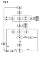
Figur 2 die prinzipiellen Schritte des Verfahrens zur Diagnose in der Heizungsanlage.
-
FIG. 1 an embodiment of a heating system according to the invention, -
FIG. 2 the basic steps of the procedure for diagnosis in the heating system.
Das Ausführungsbeispiel in
Im zweiten Teilheizkreis 18 wird kaltes Brauchwasser zum Wärmetauscher 20 transportiert, wo es erwärmt wird, anschließend wird das warme Brauchwasser zum Endnutzer geleitet. Ein Sensor 30 misst die Temperatur des Kaltwassers vor Eintritt durch den Wärmetauscher 20, ein Sensor 32 misst die Temperatur des erwärmten Kaltwassers nach Austritt.In the second Teilheizkreis 18 cold service water is transported to the
Bei dem Wärmeerzeuger 12 kann es sich um verschiedenartige Heizgeräte handeln, welche mit fossilen oder erneuerbaren Ressourcen betrieben werden. Im Ausführungsbeispiel befinden sich ein Gasbrenner 33 und der Wärmetauscher 14 im Wärmeerzeuger 12. Hierbei wird dem Wärmeerzeuger 12 mit Hilfe eines Gebläses 34 über eine Leitung 36 ein Gas-Luft-Gemisch zugeführt. In dieser Leitung 36 befindet sich weiter ein Ventil 38. Abgasprodukte werden über eine Abgasleitung 40 nach außen geführt. Durch eine vom Gasbrenner 33 erzeugte Flamme wird das Fluid, welches durch den Wärmetauscher 14 zirkuliert, erwärmt.The
Im Ausführungsbeispiel in
Alternativ kann sich die Steuer- und/oder Regeleinheit 44 auch innerhalb des Wärmeerzeugers 12 befinden. Andere Ausführungsformen sind ebenso denkbar. Dasselbe trifft auf die Anzeige 42 zu.Alternatively, the control and / or regulating
Zur Diagnose der Heizungsanlage 10 läuft ein Verfahren ab, welches anhand der
Die Zeit zur Erwärmung des Fluids durch den Wärmetauscher 14, 20, kurz Aufwärmzeit genannt, dessen Wärmeübertragungskoeffizient und die Temperaturdifferenz zwischen Vorlauf- und Rücklauftemperatur des Wärmetauschers 14, 20 sind systeminhärente Parameter und werden erfindungsgemäß als Indikatoren für eine verminderte Funktionstüchtigkeit des Wärmetauschers 14, 20, insbesondere aufgrund Verschmutzung, herangezogen. So sinkt der Wärmeübertragungskoeffizient bei zunehmendem Widerstand des Wärmetauschers 14, 20, was beispielsweise genau dann der Fall ist, wenn die Oberfläche des Wärmetauschers 14, 20 zunehmend verschmutzt ist. In diesem Fall sinkt auch die Leistungsfähigkeit des Wärmetauschers 14, 20, was zum einen zu einer höheren Aufwärmzeit führt, zum anderen, sofern man eine feste Laufzeit vorgibt, zu einer geringeren Temperaturdifferenz nach Ablauf dieser Zeit.The time for heating the fluid through the
Während der Wärmeübertragungskoeffizient und die Temperaturdifferenz während des Betriebs des Gasbrenners 33 bestimmt werden, ist die Bestimmung der Aufwärmzeit abhängig vom Brennerstart. Die Zeitmessung beginnt bei Brennerstart und endet, sobald eine Solltemperatur für das Fluid, beispielsweise für das Brauchwasser oder Heizwasser, erreicht wurde.While the heat transfer coefficient and the temperature difference are determined during the operation of the
Kern des Verfahrens ist die Ausgabe einer Meldung, wenn eine Erwärmung des Fluids um eine bestimmte oder bestimmbare Temperatur länger als eine vorbestimmte oder vorbestimmbare Zeit benötigt oder wenn die Erwärmung durch den Wärmetauscher 14, 20 eines bestimmten oder bestimmbaren Massenstroms des Fluids unterhalb einer vorbestimmten oder vorbestimmbaren Temperaturdifferenz bleibt. Auch beide Fälle können eintreten. Die Meldung wird für spätere Zwecke, wie für eine Prognose oder Diagnose, gespeichert, so dass sie zu jedem beliebigen Zeitpunkt abrufbar ist.The core of the method is the output of a message when a heating of the fluid by a certain or determinable temperature longer than a predetermined or predeterminable time needed or if the heating by the
Das Verfahren ist prinzipiell auf beliebige Wärmetauscher anwendbar. Im Folgenden wird es anhand des Wärmetauschers 14 erläutert.The method is applicable in principle to any heat exchanger. In the following, it will be explained with reference to the
Zu Beginn des Verfahrens, in Schritt 50, gibt der Anwender den oder die Parameter ein, anhand derer die Diagnose durchgeführt werden soll. Er kann eine Diagnose anhand der Aufwärmzeit, des Wärmeübertragungskoeffizienten oder der Temperaturdifferenz zwischen Vorlauf- und Rücklauftemperatur auswählen. Es können auch mehrere Modi gleichzeitig gewählt werden, welche dann parallel oder seriell durchgeführt werden. Im Folgenden wird der Fall betrachtet, dass alle Modi gewählt und parallel ausgeführt werden.At the beginning of the procedure, at
In Schritt 52 werden die Vorlauftemperatur über den Sensor 26 und die Rücklauftemperatur über den Sensor 28 gemessen. Weiter wird ein Sollwert für eine Temperatur des Fluids, wie ein Sollwert für die Temperatur des Heizwassers und des Brauchwassers, vorgegeben.In
In den Schritten 53, 54 und 55 werden die für das Verfahren notwendigen Werte vorgegeben oder berechnet, sofern sie noch nicht vorhanden sind. Für gleiche Systeme können die Werte vorgegeben werden. Beispielsweise können sie als Standardwerte gesetzt werden, die automatisch verwendet oder vom Anwender gewählt werden. Sie können auch vom Anwender eingegeben werden. Für neue oder gewartete Systeme können die Werte neu eingestellt oder neu berechnet werden.In steps 53, 54 and 55, the values necessary for the method are specified or calculated, if they are not yet present. The values can be specified for the same systems. For example, they can be set as defaults that are used automatically or chosen by the user. They can also be entered by the user. For new or maintained systems, the values can be reset or recalculated.
Für die Aufwärmzeit wird in Schritt 53 ein Schwellenwert 56 vorgegeben oder berechnet. Weiter kann ein Wert bzw. eine Maximalzahl 58 bestimmt werden, welche eine obere Schranke für die Anzahl der Fälle, in denen die Aufwärmzeit den Schwellenwert 56 erreicht oder übersteigt, darstellt. Beträgt die Maximalzahl 58 beispielsweise 20, so ergeht eine Meldung, wenn der 21. Fall einer erhöhten Aufwärmzeit eintritt. Der Schwellenwert 56 liegt im System als Standardwert vor oder kann vom Anwender geändert oder vorgegeben werden.For the warm-up time, a
Für den Wärmeübertragungskoeffizienten als Indikator für eine verminderte Funktionstüchtigkeit des Wärmetauschers 14 wird in Schritt 54 ein Schwellenwert 60 kSchwelle vorgegeben oder berechnet. Für die Berechnung werden ideale Wärmeübertragungsverhältnisse des Wärmetauschers 14 vorausgesetzt. Der Schwellenwert 60 wird über den Ausdruck ![]()
![]()
Zu Schritt 54 gehört auch die Vorgabe einer Maximalzahl 62 für den Wärmeübertragungskoeffizienten, ab welcher eine Meldung über die verminderte Funktionstüchtigkeit des Wärmetauschers 14 ausgegeben werden soll. Die Maximalzahl 62 gibt eine obere Schranke für die Anzahl der Fälle vor, in denen der Wärmeübertragungskoeffizient den Schwellenwert 60 unterschreitet.At
Wird die Temperaturdifferenz zwischen Vorlauf und Rücklauf des Wärmetauschers 14 als Indikator herangezogen, so wird in Schritt 55 ein Schwellenwert 64 und eine Maximalzahl 66 für die Temperaturdifferenz vorgegeben oder berechnet, analog zu den Schritten 53 und 54. Die Maximalzahl 66 ist eine obere Schranke für die Anzahl der Fälle, in denen die Temperaturdifferenz den Schwellenwert 64 unterschreitet. Wurden die Vorlaufund Rücklauftemperatur noch nicht gemessen, beispielsweise weil Schritt 52 übersprungen wurde, so wird dies in Schritt 55 nachgeholt.If the temperature difference between the flow and return of the
Soll die Leistung der Pumpe 22 zusammen mit der Temperaturdifferenz als Indikator für eine verminderte Funktionstüchtigkeit des Wärmetauschers 14 mit herangezogen werden, so wird in Schritt 55 ein Schwellenwert 65 für die Leistung der Pumpe 22 zusätzlich vorgegeben. Alternativ kann er berechnet werden. Die Maximalzahl 66 ist dann eine obere Schranke für die Anzahl der Fälle, in denen die Temperaturdifferenz den Schwellenwert 64 erreicht oder unterschreitet und die Leistung der Pumpe 22 den Schwellenwert 67 erreicht oder überschreitet.If the power of the
Alle Werte werden gespeichert und können vom Anwender abgerufen oder geändert werden.All values are stored and can be recalled or changed by the user.
In Schritt 68 werden ein Zähler 70 für die Aufwärmzeit, ein Zähler 72 für den Wärmeübertragungskoeffizienten und ein Zähler 74 für die Temperaturdifferenz initiiert. Beispielsweise werden sie auf 0 gesetzt.In
Sobald der Wärmeerzeuger 12 startet, beginnt in Schritt 76 eine Zeitmessung zur Bestimmung der Aufwärmzeit des Fluids durch den Wärmetauscher 14. Erreicht das Heizwasser die vorgegebene Sollwerttemperatur, wird die Zeitmessung beendet. Die verstrichene Zeit wird als Aufwärmzeit abgespeichert.As soon as the
In Schritt 77 wird der Wärmeübertragungskoeffizient berechnet. Hierfür wird die Formel ![]()
zugrunde gelegt. Hier ist nun ΔT die (variable) Temperaturdifferenz zwischen dem Wärmetauscher 14 und dem Heizwasser und 
![]()
based on. Here now Δ T is the (variable) temperature difference between the
Dabei wurde ΔT 2 ≥ ΔT 1 angenommen, damit die mittlere logarithmische Temperaturdifferenz positiv ist. ΔT2 und ΔT1 sind folgendermaßen definiert: Am ersten Eintritt des Wärmetauschers 14 wird die Temperatur TEintritt1 der heißen Luft gemessen bzw. die Temperatur des Wärmetauschers 14. Am ersten Austritt herrscht die Temperatur TAustritt1 der erkalteten Luft in der Abgasleitung. Beim zweiten Eintritt, dem Eintritt des Rücklaufheizwassers in den Wärmetauscher 14, wurde in Schritt 52 über den Sensor 28 die Rücklauftemperatur TEintritt2 gemessen, und am zweiten Austritt aus dem Wärmetauscher die Vorlauftemperatur TAustritt2 durch den Sensor 26. Man berechnet nun die Differenzen ΔT1 := |TEintritt1 - TAustritt2| und ΔT2 := |TAustritt1-TEintritt2|, sofern ΔT1 ≥ ΔT2. Sonst ist ΔT2 := |TEintritt1 - TAustritt2| und ΔT1 := |TAustritt1 - TEintritt2|.Here, Δ T 2 ≥ Δ T 1 was adopted, so that the log mean temperature difference is positive. ΔT 2 and ΔT 1 are defined as follows: At the first inlet of the
In Schritt 78 wird die Berechnung der Temperaturdifferenz zwischen der Vorlaufund Rücklauftemperatur durchgeführt. Wurden die Vorlauf- und Rücklauftemperatur noch nicht gemessen, beispielsweise weil Schritt 52 übersprungen wurde, so wird die Messung vor der Berechnung der Temperaturdifferenz durchgeführt.In
In Schritt 80 findet die Abfrage statt, ob die jeweiligen Parameter ihren zugehörigen Schwellenwert erreichen: Es wird abgefragt, ob die Aufwärmzeit größer als der Schwellenwert 56 ist, ob der Wärmeübertragungskoeffizient kleiner als der Schwellenwert 60 ist und ob die Temperaturdifferenz kleiner als der Schwellenwert 64 ist.In
Trifft dies nicht zu (Schritt 82), so bleiben die Zähler 70, 72, 74 unverändert. Das Verfahren wird in den Schritten 76, 77 und/oder 78 fortgesetzt, je nachdem, ob die Aufwärmzeit, der Wärmeübertragungskoeffizient und/oder die Temperaturdifferenz ausgewählt wurden (Schritt 50).If this is not true (step 82), the
Ergibt die Abfrage in Schritt 80 ein Ja, ist die Aufwärmzeit also größer als der Schwellenwert 56 oder der Wärmeübertragungskoeffizient kleiner als der Schwellenwert 60 oder die Temperaturdifferenz kleiner als der Schwellenwert 64, so werden die Zähler 70, 72, 74 in Schritt 84 erhöht, beispielsweise um 1.If the query in
Selbstverständlich sind Mischformen denkbar, zum Beispiel, die Aufwärmzeit ist größer als der Schwellenwert 56 und der Wärmeübertragungskoeffizient ist kleiner als der Schwellenwert 60. Dann werden der Zähler 70 und der Zähler 72 erhöht. Oder die Temperaturdifferenz ist kleiner als der Schwellenwert 64 und die Aufwärmzeit größer als der Schwellenwert 56. Dann werden der Zähler 74 und der Zähler 72 erhöht, usw. Welche und wieviele Zähler erhöht wurden, kann auch einen Hinweis auf eine verminderte Funktionsfähigkeit des Wärmetauschers 14 geben. Deshalb wird der momentane Stand der Zähler 70, 72, 76 abgespeichert und ist zu jedem Zeitpunkt auslesbar.Of course, hybrids are conceivable, for example, the warm-up time is greater than
In Schritt 86 wird abgefragt, ob mindestens einer der Zähler 70, 72, 76 die zugehörige Maximalzahl 64, 66, 68 erreicht oder überschritten hat.In
Ist dem nicht so, so beginnt das Verfahren wieder bei Schritt 76, Schritt 77 und Schritt 78, sofern alle drei Modi im parallelen Durchlauf gewählt wurden, wie in diesem Ausführungsbeispiel angenommen. Der Wärmeerzeuger 14 läuft weiter und es wird von neuem geprüft, ob eine verminderte Funktion oder Fehlfunktion vorliegt.If not, the method begins again at
Wurden nicht alle Modi gewählt, beispielsweise nur einer, so wird das Verfahren nach Schritt 82 in Schritt 76, Schritt 77 oder Schritt 78 fortgesetzt, je nachdem, welcher Modus gewählt wurde. Entsprechend sind Mischformen möglich. Auch eine serielle Verarbeitung der Schritte 76, 77, 78 ist möglich, was jedoch nicht dargestellt ist.If not all modes have been selected, for example only one, then the method continues after
Das Verfahren kann zwischenzeitlich unterbrochen oder vorzeitig beendet werden, um wieder in einem Schritt nach Wahl fortzusetzen, beispielsweise in einem der Schritte 50, 52, 53, 54, 55 usw.The process may be interrupted in the meantime or prematurely ended to resume in a step of choice, for example in one of
Wird das Verfahren beispielsweise in Schritt 80, oder einem anderen Schritt, unterbrochen und wählt der Anwender Schritt 50, so entspricht dies einer Art Neustart. Bereits gemessene oder berechnete Parameter, wie die Aufwärmzeit, oder Meldungen wurden gespeichert und sind auslesbar. Es können neue Werte eingegeben werden, die der Diagnose zugrunde gelegt werden, oder es werden voreingestellte Standardwerte oder bereits früher eingegebene Werte verwendet.For example, if the method is interrupted in
Wird beispielsweise von Schritt 84, oder einem anderen Schritt, in Schritt 68 gesprungen, so entspricht dies einer Art Zurücksetzen. In Schritt 68 werden die Zähler 70, 72, 74 initiiert, beispielsweise auf 0 gesetzt. War beispielsweise mindestens einer der Zähler 70, 72, 74 größer als dieser Initialwert so wird er wieder auf diesen zurückgesetzt. Damit beginnt das Verfahren mit der Abzählung der Verletzungsfälle von neuem, verwendet aber die bereits eingegeben Werte und Messwerte.For example, jumping from
Das Verfahren kann auch so programmiert werden, dass es nach einem gewählten Schritt zu einem anderen wählbaren Schritt automatisch wechselt. Es kann auch vollkommen abgestellt werden.The method may also be programmed to automatically switch to another selectable step after a selected step. It can also be turned off completely.
Ergibt in Schritt 86 die Abfrage, dass mindestens eine der Maximalzahlen 58, 62, 66 erreicht oder überschritten wurde, so wird in Schritt 88 eine entsprechende Meldung darüber ausgegeben und gespeichert. Mit abgespeichert wird das Datum und die Uhrzeit der Meldung. Beispielsweise kann die Meldung Text beinhalten, der besagt, dass die Funktionstüchtigkeit des Wärmetauschers 14 vermindert ist, insbesondere aufgrund einer Verschmutzung. Der Text kann zusätzlich besagen, dass der Wärmetauscher 14 einer Wartung oder Reinigung oder dergleichen bedarf. Die Meldung kann zusätzlich oder allein aus einem Blinken einer Leuchtquelle, wie beispielsweise einer Leuchtdiode, bestehen, oder aus einem Ton, wie einem einmaligen oder mehrmaligen Piepston. Andere Meldungsarten sind ebenso denkbar. Die Meldung kann so lange bestehen, bis der Anwender sie aktiv beendet. Denkbar ist auch eine einmalige Ausgabe, die nicht aktiv beendet werden muss. Die Meldung wird zur Abrufung zu einem späteren Zeitpunkt aufgezeichnet.If, in
So kann in Schritt 88 beispielsweise ein Piepston für einige Sekunden ergehen, parallel hierzu leuchtet oder blinkt ein rotes Licht so lange, bis der Anwender bestätigt, dass er die Meldung zur Kenntnis genommen hat, beispielsweise über einen Knopfdruck oder einen gesprochenen Befehl.For example, in
Der Wärmeerzeuger 12 läuft nach erfolgter Meldung weiter in normalem Betrieb, auch wenn keine Wartung oder Reinigung oder dergleichen durchgeführt wurde, und auch wenn die Meldung weiter besteht.The
In Schritt 90 wird abgefragt, ob eine Wartung oder Reinigung oder dergleichen durchgeführt wurde.In
Ist dem nicht so, so läuft das Verfahren bei Schritt 76, Schritt 77 und Schritt 78 weiter, falls alle drei Modi gewählt wurden. Die Meldung wird weiterhin ausgegeben. Beispielsweise besteht weiter das Blinken einer Leuchtdiode.If not, the method continues at
Nach erfolgter Wartung oder Reinigung, das heißt, die Abfrage in Schritt 90 wurde bejaht, werden in Schritt 92 die Parameterwerte, wie die Aufwärmzeit, der Wärmeübertragungskoeffizient, die Temperaturdifferenz, die Vorlauf- und Rücklauftemperaturen, die Zähler 70, 72, 74, zurückgesetzt. Das Verfahren startet wieder bei Schritt 50, und die Diagnose des Wärmeerzeugers 14 beginnt von neuem.After maintenance or cleaning, that is, the query in
Alle Werte, ob eingegeben, berechnet oder im Laufe des Verfahrens bestimmt, werden gespeichert und aufgezeichnet. Auch der Zeitpunkt ihrer Entstehung wird abgespeichert. Beispielsweise kann in Erfahrung gebracht werden, wie schnell hintereinander die Aufwärmzeit, der Wärmeübertragungskoeffizient oder die Temperaturdifferenz ihre entsprechenden Schwellenwerte 56, 60, 64 nicht eingehalten haben, wann die entsprechenden Zähler 70, 72, 74 erhöht wurden und wann die Maximalzahl 58, 62, 66 erreicht wurde. Weiter wird der Zeitpunkt und die Art der Meldung in Schritt 88 gespeichert. Nach einer Wartung kann der Speicher zurückgesetzt werden, um einen Speicherüberlauf zu vermeiden. Der Zeitpunkt der Wartung bleibt dabei erhalten. Der Speicher kann auch per Hand zurückgesetzt werden. Dem Anwender stehen also alle Daten für Diagnose- und Prognosezwecke zur Verfügung.All values, whether entered, calculated or determined in the course of the procedure, are stored and recorded. The time of their creation is also stored. For example, it can be learned how quickly the warm-up time, the heat transfer coefficient or the temperature difference did not meet their
Claims (10)

berechnet wird, wobei c die Wärmekapazität des Fluids, ΔTSchwelle die Temperaturdifferenz, beispielsweise zwischen dem Wärmetauscher (14, 20) und dem Fluid oder die Temperaturdifferenz von Vorlauftemperatur zu Rücklauftemperatur, m der Massenstrom des Fluids, A die freie Wärmeübertragungsfläche und
where c is the heat capacity of the fluid, ΔT threshold is the temperature difference, for example between the heat exchanger (14, 20) and the fluid, or the temperature difference between flow temperature and return temperature, m the mass flow of the fluid, A the free flow Heat transfer surface and
Applications Claiming Priority (1)
| Application Number | Priority Date | Filing Date | Title |
|---|---|---|---|
| DE102014202478.1A DE102014202478A1 (en) | 2014-02-12 | 2014-02-12 | Method for diagnosing a heating system with at least one heat exchanger |
Publications (2)
| Publication Number | Publication Date |
|---|---|
| EP2908059A1 true EP2908059A1 (en) | 2015-08-19 |
| EP2908059B1 EP2908059B1 (en) | 2019-03-13 |
Family
ID=52394134
Family Applications (1)
| Application Number | Title | Priority Date | Filing Date |
|---|---|---|---|
| EP15151896.6A Active EP2908059B1 (en) | 2014-02-12 | 2015-01-21 | Method for the diagnosis of a heating installation with at least one heat exchanger |
Country Status (2)
| Country | Link |
|---|---|
| EP (1) | EP2908059B1 (en) |
| DE (1) | DE102014202478A1 (en) |
Cited By (4)
| Publication number | Priority date | Publication date | Assignee | Title |
|---|---|---|---|---|
| EP3434983A1 (en) * | 2017-07-25 | 2019-01-30 | Samson AG | Method for diagnosing a heat exchanger |
| EP3441694A1 (en) * | 2017-08-11 | 2019-02-13 | Robert Bosch GmbH | Method for operating a thermotechnical system |
| EP4036484A1 (en) | 2021-01-29 | 2022-08-03 | Viessmann Climate Solutions SE | Heating system and method for operating a heating system |
| EP4206554A1 (en) * | 2021-12-29 | 2023-07-05 | Bosch Termoteknik Isitma ve Klima Sanayi Ticaret Anonim Sirketi | System for determining the remaining service life of the heat exchanger of water heaters |
Families Citing this family (1)
| Publication number | Priority date | Publication date | Assignee | Title |
|---|---|---|---|---|
| WO2023235393A1 (en) * | 2022-06-01 | 2023-12-07 | Laars Heating Systems Company | System and method for determining heat transfer capacity of an indirect water heater |
Citations (8)
| Publication number | Priority date | Publication date | Assignee | Title |
|---|---|---|---|---|
| EP0155826A2 (en) * | 1984-03-23 | 1985-09-25 | International Control Automation Finance S.A. | Heat exchanger performance monitors |
| EP0617239A2 (en) * | 1993-03-23 | 1994-09-28 | Armin Niederer | Method for monitoring the state of clogging and/or calcification of heat exchangers in heating or cooling systems |
| US20040153280A1 (en) * | 2001-05-03 | 2004-08-05 | Matts Lindgren | Method and arrangement for controlling the temperature of the outstream flow from a heat exchanger and measuring produced heat |
| US20050011278A1 (en) * | 2003-07-18 | 2005-01-20 | Brown Gregory C. | Process diagnostics |
| US20050133211A1 (en) * | 2003-12-19 | 2005-06-23 | Osborn Mark D. | Heat exchanger performance monitoring and analysis method and system |
| WO2007031087A1 (en) * | 2005-09-15 | 2007-03-22 | Danfoss A/S | Heat exchanger and method for regulating a heat exchanger |
| US20100206869A1 (en) * | 2009-02-13 | 2010-08-19 | General Electric Company | Heat pump water heater control |
| EP2280230A2 (en) * | 2009-07-23 | 2011-02-02 | Viessmann Werke GmbH & Co. KG | Method for monitoring the contamination of a heat exchanger on a heater |
-
2014
- 2014-02-12 DE DE102014202478.1A patent/DE102014202478A1/en not_active Ceased
-
2015
- 2015-01-21 EP EP15151896.6A patent/EP2908059B1/en active Active
Patent Citations (8)
| Publication number | Priority date | Publication date | Assignee | Title |
|---|---|---|---|---|
| EP0155826A2 (en) * | 1984-03-23 | 1985-09-25 | International Control Automation Finance S.A. | Heat exchanger performance monitors |
| EP0617239A2 (en) * | 1993-03-23 | 1994-09-28 | Armin Niederer | Method for monitoring the state of clogging and/or calcification of heat exchangers in heating or cooling systems |
| US20040153280A1 (en) * | 2001-05-03 | 2004-08-05 | Matts Lindgren | Method and arrangement for controlling the temperature of the outstream flow from a heat exchanger and measuring produced heat |
| US20050011278A1 (en) * | 2003-07-18 | 2005-01-20 | Brown Gregory C. | Process diagnostics |
| US20050133211A1 (en) * | 2003-12-19 | 2005-06-23 | Osborn Mark D. | Heat exchanger performance monitoring and analysis method and system |
| WO2007031087A1 (en) * | 2005-09-15 | 2007-03-22 | Danfoss A/S | Heat exchanger and method for regulating a heat exchanger |
| US20100206869A1 (en) * | 2009-02-13 | 2010-08-19 | General Electric Company | Heat pump water heater control |
| EP2280230A2 (en) * | 2009-07-23 | 2011-02-02 | Viessmann Werke GmbH & Co. KG | Method for monitoring the contamination of a heat exchanger on a heater |
Cited By (7)
| Publication number | Priority date | Publication date | Assignee | Title |
|---|---|---|---|---|
| EP3434983A1 (en) * | 2017-07-25 | 2019-01-30 | Samson AG | Method for diagnosing a heat exchanger |
| CN109297733A (en) * | 2017-07-25 | 2019-02-01 | 大力士股份有限公司 | Heat exchanger diagnostic method |
| CN109297733B (en) * | 2017-07-25 | 2021-08-31 | 大力士股份有限公司 | Heat exchanger diagnostic method |
| EP3441694A1 (en) * | 2017-08-11 | 2019-02-13 | Robert Bosch GmbH | Method for operating a thermotechnical system |
| EP4036484A1 (en) | 2021-01-29 | 2022-08-03 | Viessmann Climate Solutions SE | Heating system and method for operating a heating system |
| DE102021200834A1 (en) | 2021-01-29 | 2022-08-04 | Viessmann Climate Solutions Se | HEATING SYSTEM AND METHOD OF OPERATING A HEATING SYSTEM |
| EP4206554A1 (en) * | 2021-12-29 | 2023-07-05 | Bosch Termoteknik Isitma ve Klima Sanayi Ticaret Anonim Sirketi | System for determining the remaining service life of the heat exchanger of water heaters |
Also Published As
| Publication number | Publication date |
|---|---|
| EP2908059B1 (en) | 2019-03-13 |
| DE102014202478A1 (en) | 2015-08-13 |
Similar Documents
| Publication | Publication Date | Title |
|---|---|---|
| EP2908059B1 (en) | Method for the diagnosis of a heating installation with at least one heat exchanger | |
| DE60008983T2 (en) | Thermostat fault diagnosis system for the cooling system of a motor vehicle engine | |
| EP1936290B1 (en) | Method and device for detecting the hydraulic state of a heating system | |
| DE10359581B4 (en) | Method for controlling a vehicle engine cooling system | |
| EP3034955B1 (en) | Method for carrying out an automated hydraulic compensation of a heating installation | |
| DE112010001317T5 (en) | Thermostat and cooling device for vehicles | |
| DE102014016421B4 (en) | Method for operating a fluid-carrying device and corresponding fluid-carrying device | |
| DE102010054979A1 (en) | Valve arrangement and method for actuating a valve | |
| DE102014106362A1 (en) | Method for monitoring the opening state of a control valve of a coolant circuit of an internal combustion engine and device therefor | |
| DE102015222436B4 (en) | Fault diagnosis procedure of a thermostat | |
| EP3180503B1 (en) | Method for operating a fluid circuit of a motor vehicle, and corresponding fluid circuit | |
| EP3217104B1 (en) | Apparatus and method for determining the operating conditions of a radiator with a radiator valve | |
| DE102007033564B3 (en) | Method for operating a stratified charge storage and domestic hot water system | |
| EP1662240B1 (en) | Heating cost distributor | |
| EP4141334A1 (en) | Method for operating a heater, computer program, storage medium, regulation and control device, heater and use of a signal | |
| DE102013008743B3 (en) | Method for controlling a coolant flow in a motor vehicle and motor vehicle | |
| EP1403588B1 (en) | Heating installation for a building | |
| EP2280230B1 (en) | Method for monitoring the contamination of a heat exchanger on a heater | |
| DE102005048313B4 (en) | Method for diagnosing the condition of a thermostat | |
| DE102017124099A1 (en) | Method for determining a maintenance interval | |
| EP4036484A1 (en) | Heating system and method for operating a heating system | |
| DE102022209399B3 (en) | Method for diagnosing a hydrogen sensor, hydrogen sensor, computer program and computer-readable medium | |
| DE102015202790B4 (en) | Method for diagnosing a cooling circuit control in a vehicle and cooling circuit with such a cooling circuit control | |
| DE10227163B4 (en) | Method for determining a criterion for changing an actual value from a plurality of successively obtained measured values and heating device with a control device designed to carry out the method | |
| DE10014752A1 (en) | Method and appliance for monitoring thermostat valve in automobile secondary cooling circuit by comparison of cooling circuit temperature characteristic with specific characteristic |
Legal Events
| Date | Code | Title | Description |
|---|---|---|---|
| PUAI | Public reference made under article 153(3) epc to a published international application that has entered the european phase |
Free format text: ORIGINAL CODE: 0009012 |
|
| AK | Designated contracting states |
Kind code of ref document: A1 Designated state(s): AL AT BE BG CH CY CZ DE DK EE ES FI FR GB GR HR HU IE IS IT LI LT LU LV MC MK MT NL NO PL PT RO RS SE SI SK SM TR |
|
| AX | Request for extension of the european patent |
Extension state: BA ME |
|
| 17P | Request for examination filed |
Effective date: 20160219 |
|
| RBV | Designated contracting states (corrected) |
Designated state(s): AL AT BE BG CH CY CZ DE DK EE ES FI FR GB GR HR HU IE IS IT LI LT LU LV MC MK MT NL NO PL PT RO RS SE SI SK SM TR |
|
| STAA | Information on the status of an ep patent application or granted ep patent |
Free format text: STATUS: EXAMINATION IS IN PROGRESS |
|
| 17Q | First examination report despatched |
Effective date: 20170608 |
|
| REG | Reference to a national code |
Ref country code: DE Ref legal event code: R079 Ref document number: 502015008291 Country of ref document: DE Free format text: PREVIOUS MAIN CLASS: F24D0019000000 Ipc: F24D0019100000 |
|
| RIC1 | Information provided on ipc code assigned before grant |
Ipc: F28F 19/00 20060101ALI20180803BHEP Ipc: F28F 27/00 20060101ALI20180803BHEP Ipc: F24D 19/10 20060101AFI20180803BHEP Ipc: F24D 19/00 20060101ALI20180803BHEP Ipc: F24H 1/52 20060101ALI20180803BHEP |
|
| GRAP | Despatch of communication of intention to grant a patent |
Free format text: ORIGINAL CODE: EPIDOSNIGR1 |
|
| STAA | Information on the status of an ep patent application or granted ep patent |
Free format text: STATUS: GRANT OF PATENT IS INTENDED |
|
| INTG | Intention to grant announced |
Effective date: 20180918 |
|
| GRAS | Grant fee paid |
Free format text: ORIGINAL CODE: EPIDOSNIGR3 |
|
| GRAA | (expected) grant |
Free format text: ORIGINAL CODE: 0009210 |
|
| STAA | Information on the status of an ep patent application or granted ep patent |
Free format text: STATUS: THE PATENT HAS BEEN GRANTED |
|
| AK | Designated contracting states |
Kind code of ref document: B1 Designated state(s): AL AT BE BG CH CY CZ DE DK EE ES FI FR GB GR HR HU IE IS IT LI LT LU LV MC MK MT NL NO PL PT RO RS SE SI SK SM TR |
|
| REG | Reference to a national code |
Ref country code: GB Ref legal event code: FG4D Free format text: NOT ENGLISH |
|
| REG | Reference to a national code |
Ref country code: CH Ref legal event code: EP Ref country code: AT Ref legal event code: REF Ref document number: 1108241 Country of ref document: AT Kind code of ref document: T Effective date: 20190315 |
|
| REG | Reference to a national code |
Ref country code: IE Ref legal event code: FG4D Free format text: LANGUAGE OF EP DOCUMENT: GERMAN |
|
| REG | Reference to a national code |
Ref country code: DE Ref legal event code: R096 Ref document number: 502015008291 Country of ref document: DE |
|
| REG | Reference to a national code |
Ref country code: NL Ref legal event code: FP |
|
| REG | Reference to a national code |
Ref country code: LT Ref legal event code: MG4D |
|
| PG25 | Lapsed in a contracting state [announced via postgrant information from national office to epo] |
Ref country code: SE Free format text: LAPSE BECAUSE OF FAILURE TO SUBMIT A TRANSLATION OF THE DESCRIPTION OR TO PAY THE FEE WITHIN THE PRESCRIBED TIME-LIMIT Effective date: 20190313 Ref country code: NO Free format text: LAPSE BECAUSE OF FAILURE TO SUBMIT A TRANSLATION OF THE DESCRIPTION OR TO PAY THE FEE WITHIN THE PRESCRIBED TIME-LIMIT Effective date: 20190613 Ref country code: LT Free format text: LAPSE BECAUSE OF FAILURE TO SUBMIT A TRANSLATION OF THE DESCRIPTION OR TO PAY THE FEE WITHIN THE PRESCRIBED TIME-LIMIT Effective date: 20190313 Ref country code: FI Free format text: LAPSE BECAUSE OF FAILURE TO SUBMIT A TRANSLATION OF THE DESCRIPTION OR TO PAY THE FEE WITHIN THE PRESCRIBED TIME-LIMIT Effective date: 20190313 |
|
| PG25 | Lapsed in a contracting state [announced via postgrant information from national office to epo] |
Ref country code: GR Free format text: LAPSE BECAUSE OF FAILURE TO SUBMIT A TRANSLATION OF THE DESCRIPTION OR TO PAY THE FEE WITHIN THE PRESCRIBED TIME-LIMIT Effective date: 20190614 Ref country code: BG Free format text: LAPSE BECAUSE OF FAILURE TO SUBMIT A TRANSLATION OF THE DESCRIPTION OR TO PAY THE FEE WITHIN THE PRESCRIBED TIME-LIMIT Effective date: 20190613 Ref country code: RS Free format text: LAPSE BECAUSE OF FAILURE TO SUBMIT A TRANSLATION OF THE DESCRIPTION OR TO PAY THE FEE WITHIN THE PRESCRIBED TIME-LIMIT Effective date: 20190313 Ref country code: HR Free format text: LAPSE BECAUSE OF FAILURE TO SUBMIT A TRANSLATION OF THE DESCRIPTION OR TO PAY THE FEE WITHIN THE PRESCRIBED TIME-LIMIT Effective date: 20190313 Ref country code: LV Free format text: LAPSE BECAUSE OF FAILURE TO SUBMIT A TRANSLATION OF THE DESCRIPTION OR TO PAY THE FEE WITHIN THE PRESCRIBED TIME-LIMIT Effective date: 20190313 |
|
| PG25 | Lapsed in a contracting state [announced via postgrant information from national office to epo] |
Ref country code: SK Free format text: LAPSE BECAUSE OF FAILURE TO SUBMIT A TRANSLATION OF THE DESCRIPTION OR TO PAY THE FEE WITHIN THE PRESCRIBED TIME-LIMIT Effective date: 20190313 Ref country code: RO Free format text: LAPSE BECAUSE OF FAILURE TO SUBMIT A TRANSLATION OF THE DESCRIPTION OR TO PAY THE FEE WITHIN THE PRESCRIBED TIME-LIMIT Effective date: 20190313 Ref country code: EE Free format text: LAPSE BECAUSE OF FAILURE TO SUBMIT A TRANSLATION OF THE DESCRIPTION OR TO PAY THE FEE WITHIN THE PRESCRIBED TIME-LIMIT Effective date: 20190313 Ref country code: AL Free format text: LAPSE BECAUSE OF FAILURE TO SUBMIT A TRANSLATION OF THE DESCRIPTION OR TO PAY THE FEE WITHIN THE PRESCRIBED TIME-LIMIT Effective date: 20190313 Ref country code: PT Free format text: LAPSE BECAUSE OF FAILURE TO SUBMIT A TRANSLATION OF THE DESCRIPTION OR TO PAY THE FEE WITHIN THE PRESCRIBED TIME-LIMIT Effective date: 20190713 Ref country code: CZ Free format text: LAPSE BECAUSE OF FAILURE TO SUBMIT A TRANSLATION OF THE DESCRIPTION OR TO PAY THE FEE WITHIN THE PRESCRIBED TIME-LIMIT Effective date: 20190313 Ref country code: ES Free format text: LAPSE BECAUSE OF FAILURE TO SUBMIT A TRANSLATION OF THE DESCRIPTION OR TO PAY THE FEE WITHIN THE PRESCRIBED TIME-LIMIT Effective date: 20190313 |
|
| PG25 | Lapsed in a contracting state [announced via postgrant information from national office to epo] |
Ref country code: SM Free format text: LAPSE BECAUSE OF FAILURE TO SUBMIT A TRANSLATION OF THE DESCRIPTION OR TO PAY THE FEE WITHIN THE PRESCRIBED TIME-LIMIT Effective date: 20190313 Ref country code: PL Free format text: LAPSE BECAUSE OF FAILURE TO SUBMIT A TRANSLATION OF THE DESCRIPTION OR TO PAY THE FEE WITHIN THE PRESCRIBED TIME-LIMIT Effective date: 20190313 |
|
| REG | Reference to a national code |
Ref country code: DE Ref legal event code: R097 Ref document number: 502015008291 Country of ref document: DE |
|
| PG25 | Lapsed in a contracting state [announced via postgrant information from national office to epo] |
Ref country code: IS Free format text: LAPSE BECAUSE OF FAILURE TO SUBMIT A TRANSLATION OF THE DESCRIPTION OR TO PAY THE FEE WITHIN THE PRESCRIBED TIME-LIMIT Effective date: 20190713 |
|
| PLBE | No opposition filed within time limit |
Free format text: ORIGINAL CODE: 0009261 |
|
| STAA | Information on the status of an ep patent application or granted ep patent |
Free format text: STATUS: NO OPPOSITION FILED WITHIN TIME LIMIT |
|
| PG25 | Lapsed in a contracting state [announced via postgrant information from national office to epo] |
Ref country code: DK Free format text: LAPSE BECAUSE OF FAILURE TO SUBMIT A TRANSLATION OF THE DESCRIPTION OR TO PAY THE FEE WITHIN THE PRESCRIBED TIME-LIMIT Effective date: 20190313 |
|
| 26N | No opposition filed |
Effective date: 20191216 |
|
| PG25 | Lapsed in a contracting state [announced via postgrant information from national office to epo] |
Ref country code: SI Free format text: LAPSE BECAUSE OF FAILURE TO SUBMIT A TRANSLATION OF THE DESCRIPTION OR TO PAY THE FEE WITHIN THE PRESCRIBED TIME-LIMIT Effective date: 20190313 |
|
| PG25 | Lapsed in a contracting state [announced via postgrant information from national office to epo] |
Ref country code: TR Free format text: LAPSE BECAUSE OF FAILURE TO SUBMIT A TRANSLATION OF THE DESCRIPTION OR TO PAY THE FEE WITHIN THE PRESCRIBED TIME-LIMIT Effective date: 20190313 |
|
| PG25 | Lapsed in a contracting state [announced via postgrant information from national office to epo] |
Ref country code: MC Free format text: LAPSE BECAUSE OF FAILURE TO SUBMIT A TRANSLATION OF THE DESCRIPTION OR TO PAY THE FEE WITHIN THE PRESCRIBED TIME-LIMIT Effective date: 20190313 |
|
| REG | Reference to a national code |
Ref country code: BE Ref legal event code: MM Effective date: 20200131 |
|
| PG25 | Lapsed in a contracting state [announced via postgrant information from national office to epo] |
Ref country code: LU Free format text: LAPSE BECAUSE OF NON-PAYMENT OF DUE FEES Effective date: 20200121 |
|
| PG25 | Lapsed in a contracting state [announced via postgrant information from national office to epo] |
Ref country code: BE Free format text: LAPSE BECAUSE OF NON-PAYMENT OF DUE FEES Effective date: 20200131 |
|
| PG25 | Lapsed in a contracting state [announced via postgrant information from national office to epo] |
Ref country code: IE Free format text: LAPSE BECAUSE OF NON-PAYMENT OF DUE FEES Effective date: 20200121 |
|
| PGFP | Annual fee paid to national office [announced via postgrant information from national office to epo] |
Ref country code: IT Payment date: 20210129 Year of fee payment: 7 Ref country code: CH Payment date: 20210122 Year of fee payment: 7 |
|
| PGFP | Annual fee paid to national office [announced via postgrant information from national office to epo] |
Ref country code: AT Payment date: 20210119 Year of fee payment: 7 |
|
| PGFP | Annual fee paid to national office [announced via postgrant information from national office to epo] |
Ref country code: GB Payment date: 20220125 Year of fee payment: 8 |
|
| PG25 | Lapsed in a contracting state [announced via postgrant information from national office to epo] |
Ref country code: MT Free format text: LAPSE BECAUSE OF FAILURE TO SUBMIT A TRANSLATION OF THE DESCRIPTION OR TO PAY THE FEE WITHIN THE PRESCRIBED TIME-LIMIT Effective date: 20190313 Ref country code: CY Free format text: LAPSE BECAUSE OF FAILURE TO SUBMIT A TRANSLATION OF THE DESCRIPTION OR TO PAY THE FEE WITHIN THE PRESCRIBED TIME-LIMIT Effective date: 20190313 |
|
| PGFP | Annual fee paid to national office [announced via postgrant information from national office to epo] |
Ref country code: NL Payment date: 20220120 Year of fee payment: 8 Ref country code: FR Payment date: 20220120 Year of fee payment: 8 |
|
| PG25 | Lapsed in a contracting state [announced via postgrant information from national office to epo] |
Ref country code: MK Free format text: LAPSE BECAUSE OF FAILURE TO SUBMIT A TRANSLATION OF THE DESCRIPTION OR TO PAY THE FEE WITHIN THE PRESCRIBED TIME-LIMIT Effective date: 20190313 |
|
| REG | Reference to a national code |
Ref country code: CH Ref legal event code: PL |
|
| REG | Reference to a national code |
Ref country code: AT Ref legal event code: MM01 Ref document number: 1108241 Country of ref document: AT Kind code of ref document: T Effective date: 20220121 |
|
| PG25 | Lapsed in a contracting state [announced via postgrant information from national office to epo] |
Ref country code: AT Free format text: LAPSE BECAUSE OF NON-PAYMENT OF DUE FEES Effective date: 20220121 |
|
| PG25 | Lapsed in a contracting state [announced via postgrant information from national office to epo] |
Ref country code: LI Free format text: LAPSE BECAUSE OF NON-PAYMENT OF DUE FEES Effective date: 20220131 Ref country code: CH Free format text: LAPSE BECAUSE OF NON-PAYMENT OF DUE FEES Effective date: 20220131 |
|
| PG25 | Lapsed in a contracting state [announced via postgrant information from national office to epo] |
Ref country code: IT Free format text: LAPSE BECAUSE OF NON-PAYMENT OF DUE FEES Effective date: 20220121 |
|
| PGFP | Annual fee paid to national office [announced via postgrant information from national office to epo] |
Ref country code: DE Payment date: 20230324 Year of fee payment: 9 |
|
| REG | Reference to a national code |
Ref country code: NL Ref legal event code: MM Effective date: 20230201 |
|
| GBPC | Gb: european patent ceased through non-payment of renewal fee |
Effective date: 20230121 |
|
| PG25 | Lapsed in a contracting state [announced via postgrant information from national office to epo] |
Ref country code: NL Free format text: LAPSE BECAUSE OF NON-PAYMENT OF DUE FEES Effective date: 20230201 Ref country code: GB Free format text: LAPSE BECAUSE OF NON-PAYMENT OF DUE FEES Effective date: 20230121 |
|
| PG25 | Lapsed in a contracting state [announced via postgrant information from national office to epo] |
Ref country code: FR Free format text: LAPSE BECAUSE OF NON-PAYMENT OF DUE FEES Effective date: 20230131 |