EP4141334A1 - Method for operating a heater, computer program, storage medium, regulation and control device, heater and use of a signal - Google Patents
Method for operating a heater, computer program, storage medium, regulation and control device, heater and use of a signal Download PDFInfo
- Publication number
- EP4141334A1 EP4141334A1 EP22191495.5A EP22191495A EP4141334A1 EP 4141334 A1 EP4141334 A1 EP 4141334A1 EP 22191495 A EP22191495 A EP 22191495A EP 4141334 A1 EP4141334 A1 EP 4141334A1
- Authority
- EP
- European Patent Office
- Prior art keywords
- bypass
- pump
- heating water
- heating
- condensing
- Prior art date
- Legal status (The legal status is an assumption and is not a legal conclusion. Google has not performed a legal analysis and makes no representation as to the accuracy of the status listed.)
- Pending
Links
- 238000000034 method Methods 0.000 title claims abstract description 31
- 238000004590 computer program Methods 0.000 title claims abstract description 9
- 230000033228 biological regulation Effects 0.000 title description 8
- 239000008236 heating water Substances 0.000 claims abstract description 69
- 238000010438 heat treatment Methods 0.000 claims abstract description 56
- 238000001514 detection method Methods 0.000 claims abstract description 10
- 230000001953 sensory effect Effects 0.000 claims abstract description 7
- 230000001105 regulatory effect Effects 0.000 claims description 5
- XLYOFNOQVPJJNP-UHFFFAOYSA-N water Substances O XLYOFNOQVPJJNP-UHFFFAOYSA-N 0.000 description 13
- 238000002485 combustion reaction Methods 0.000 description 7
- 238000010586 diagram Methods 0.000 description 6
- 239000007789 gas Substances 0.000 description 2
- 238000012544 monitoring process Methods 0.000 description 2
- 230000006641 stabilisation Effects 0.000 description 2
- 238000011105 stabilization Methods 0.000 description 2
- 230000006978 adaptation Effects 0.000 description 1
- 238000009835 boiling Methods 0.000 description 1
- 238000010276 construction Methods 0.000 description 1
- 230000001419 dependent effect Effects 0.000 description 1
- 238000011161 development Methods 0.000 description 1
- 230000018109 developmental process Effects 0.000 description 1
- 238000011156 evaluation Methods 0.000 description 1
- 239000002737 fuel gas Substances 0.000 description 1
- 238000000146 jump and return pulse sequence Methods 0.000 description 1
- 238000005259 measurement Methods 0.000 description 1
- 238000011017 operating method Methods 0.000 description 1
- 230000000630 rising effect Effects 0.000 description 1
- 230000002123 temporal effect Effects 0.000 description 1
- 238000011144 upstream manufacturing Methods 0.000 description 1
Images
Classifications
-
- F—MECHANICAL ENGINEERING; LIGHTING; HEATING; WEAPONS; BLASTING
- F24—HEATING; RANGES; VENTILATING
- F24D—DOMESTIC- OR SPACE-HEATING SYSTEMS, e.g. CENTRAL HEATING SYSTEMS; DOMESTIC HOT-WATER SUPPLY SYSTEMS; ELEMENTS OR COMPONENTS THEREFOR
- F24D19/00—Details
- F24D19/10—Arrangement or mounting of control or safety devices
- F24D19/1006—Arrangement or mounting of control or safety devices for water heating systems
- F24D19/1009—Arrangement or mounting of control or safety devices for water heating systems for central heating
- F24D19/1015—Arrangement or mounting of control or safety devices for water heating systems for central heating using a valve or valves
- F24D19/1021—Arrangement or mounting of control or safety devices for water heating systems for central heating using a valve or valves a by pass valve
-
- F—MECHANICAL ENGINEERING; LIGHTING; HEATING; WEAPONS; BLASTING
- F24—HEATING; RANGES; VENTILATING
- F24D—DOMESTIC- OR SPACE-HEATING SYSTEMS, e.g. CENTRAL HEATING SYSTEMS; DOMESTIC HOT-WATER SUPPLY SYSTEMS; ELEMENTS OR COMPONENTS THEREFOR
- F24D19/00—Details
- F24D19/10—Arrangement or mounting of control or safety devices
- F24D19/1006—Arrangement or mounting of control or safety devices for water heating systems
- F24D19/1009—Arrangement or mounting of control or safety devices for water heating systems for central heating
- F24D19/1012—Arrangement or mounting of control or safety devices for water heating systems for central heating by regulating the speed of a pump
-
- F—MECHANICAL ENGINEERING; LIGHTING; HEATING; WEAPONS; BLASTING
- F24—HEATING; RANGES; VENTILATING
- F24D—DOMESTIC- OR SPACE-HEATING SYSTEMS, e.g. CENTRAL HEATING SYSTEMS; DOMESTIC HOT-WATER SUPPLY SYSTEMS; ELEMENTS OR COMPONENTS THEREFOR
- F24D3/00—Hot-water central heating systems
- F24D3/08—Hot-water central heating systems in combination with systems for domestic hot-water supply
-
- F—MECHANICAL ENGINEERING; LIGHTING; HEATING; WEAPONS; BLASTING
- F24—HEATING; RANGES; VENTILATING
- F24H—FLUID HEATERS, e.g. WATER OR AIR HEATERS, HAVING HEAT-GENERATING MEANS, e.g. HEAT PUMPS, IN GENERAL
- F24H15/00—Control of fluid heaters
- F24H15/20—Control of fluid heaters characterised by control inputs
- F24H15/212—Temperature of the water
- F24H15/215—Temperature of the water before heating
-
- F—MECHANICAL ENGINEERING; LIGHTING; HEATING; WEAPONS; BLASTING
- F24—HEATING; RANGES; VENTILATING
- F24H—FLUID HEATERS, e.g. WATER OR AIR HEATERS, HAVING HEAT-GENERATING MEANS, e.g. HEAT PUMPS, IN GENERAL
- F24H15/00—Control of fluid heaters
- F24H15/20—Control of fluid heaters characterised by control inputs
- F24H15/238—Flow rate
-
- F—MECHANICAL ENGINEERING; LIGHTING; HEATING; WEAPONS; BLASTING
- F24—HEATING; RANGES; VENTILATING
- F24H—FLUID HEATERS, e.g. WATER OR AIR HEATERS, HAVING HEAT-GENERATING MEANS, e.g. HEAT PUMPS, IN GENERAL
- F24H15/00—Control of fluid heaters
- F24H15/20—Control of fluid heaters characterised by control inputs
- F24H15/242—Pressure
-
- F—MECHANICAL ENGINEERING; LIGHTING; HEATING; WEAPONS; BLASTING
- F24—HEATING; RANGES; VENTILATING
- F24H—FLUID HEATERS, e.g. WATER OR AIR HEATERS, HAVING HEAT-GENERATING MEANS, e.g. HEAT PUMPS, IN GENERAL
- F24H15/00—Control of fluid heaters
- F24H15/30—Control of fluid heaters characterised by control outputs; characterised by the components to be controlled
- F24H15/335—Control of pumps, e.g. on-off control
- F24H15/34—Control of the speed of pumps
-
- F—MECHANICAL ENGINEERING; LIGHTING; HEATING; WEAPONS; BLASTING
- F24—HEATING; RANGES; VENTILATING
- F24H—FLUID HEATERS, e.g. WATER OR AIR HEATERS, HAVING HEAT-GENERATING MEANS, e.g. HEAT PUMPS, IN GENERAL
- F24H15/00—Control of fluid heaters
- F24H15/30—Control of fluid heaters characterised by control outputs; characterised by the components to be controlled
- F24H15/355—Control of heat-generating means in heaters
- F24H15/36—Control of heat-generating means in heaters of burners
-
- F—MECHANICAL ENGINEERING; LIGHTING; HEATING; WEAPONS; BLASTING
- F24—HEATING; RANGES; VENTILATING
- F24H—FLUID HEATERS, e.g. WATER OR AIR HEATERS, HAVING HEAT-GENERATING MEANS, e.g. HEAT PUMPS, IN GENERAL
- F24H15/00—Control of fluid heaters
- F24H15/40—Control of fluid heaters characterised by the type of controllers
- F24H15/414—Control of fluid heaters characterised by the type of controllers using electronic processing, e.g. computer-based
- F24H15/421—Control of fluid heaters characterised by the type of controllers using electronic processing, e.g. computer-based using pre-stored data
- F24H15/429—Control of fluid heaters characterised by the type of controllers using electronic processing, e.g. computer-based using pre-stored data for selecting operation modes
-
- F—MECHANICAL ENGINEERING; LIGHTING; HEATING; WEAPONS; BLASTING
- F24—HEATING; RANGES; VENTILATING
- F24D—DOMESTIC- OR SPACE-HEATING SYSTEMS, e.g. CENTRAL HEATING SYSTEMS; DOMESTIC HOT-WATER SUPPLY SYSTEMS; ELEMENTS OR COMPONENTS THEREFOR
- F24D2200/00—Heat sources or energy sources
- F24D2200/04—Gas or oil fired boiler
- F24D2200/046—Condensing boilers
Definitions
- the present invention relates to a method for operating a condensing heating system. Furthermore, a condensing heating system is proposed, as well as a computer program that supports the execution of the method in a condensing heating system.
- Gas-fired condensing heating systems or condensing boilers are used in particular to supply heating systems in apartments, houses, etc. with heating water as required, which is routed to the radiators by means of a corresponding hot water circulation system, where it gives off its heat and then returns to the condensing heating system. there to be warmed up again.
- Such condensing heating systems usually have at least one pump which is provided in a (closed) heating water circuit. With the pump, hot water is pumped through the hot water circuit, preferably regulated depending on the desired heat output of the radiator.
- the hot water circuit can include at least one, but preferably also several, heaters. Once multiple radiators, such as bps. Radiators are provided, they can be connected in parallel or be traversed by heating water.
- condensing heating systems work modulating.
- Such Adaptation or regulation preferably takes place steplessly.
- the particular aim of this modulation is to work in an energy-saving manner, because the more precisely the power generated corresponds to the required heat output, the more efficiently the resources, in particular the fuel gas, can be used efficiently.
- the condensing heating system has a regular modulation setpoint, for example in the range of approx. 80%, which is initially set before the heating output of the condensing heating system is then adapted to the requested heat output as part of a modulation control process .
- a bypass which connects a flow of the heating water to the radiators and a return for the heating water, bypassing the at least one radiator. Therefore, when the bypass is open, heating water can flow directly from the flow to the return without flowing through a radiator.
- a differential-pressure-actuable valve is provided in this bypass, which valve can be opened and closed automatically can close, depending on the pressure difference in the bypass upstream and downstream of the valve.
- the valve can be equipped with a spring and a predetermined spring force or spring characteristic, so that the valve opens at a predetermined differential pressure. If the difference is lower, the valve remains closed and the bypass cannot flow through. Such an increased differential pressure can occur precisely in the situation described above, so that in this case the bypass opens and a further increase in pressure is avoided.
- bypass has proven to be particularly suitable if the heating water circulation is too low or the differential pressures are too high, since this could cause the flow temperatures to rise to the point of boiling and/or clearly noticeable or audible vibrations on the thermostatic valves.
- the object of the present invention is to at least partially solve the problems described with reference to the prior art.
- a method for operating a condensing heating system is to be specified, which works more gently and/or more energy-efficiently.
- a condensing boiler suitable for this purpose a computer program and a computer-readable medium are to be proposed.
- the operating method proposed here can be carried out in a condensing heating system which has at least one heating water circuit comprising at least one pump with at least one radiator and a bypass which connects a flow and a return, bypassing the at least one radiator.
- the bypass can be opened and closed by means of a valve that can be actuated by differential pressure.
- the condensing heating system is set up in particular to circulate the water in the heating water circuit by means of the pump, so that the so-called heating water flows through the at least one radiator in regular operation.
- the condensing heating system has, in particular, a so-called gas-fired condensing boiler, where the heating water fed there is heated by means of a gas furnace. The heating water thus heated reaches the radiator via the flow at an increased temperature, flows through it, gives off a large part of its heat and is then routed back to the combustion chamber.
- several heating elements can be provided, which preferably form parallel water flow paths.
- step a) it is possible for step a) to be carried out intermittently or continuously throughout the entire method, ie the modulation target value is recorded practically continuously.
- step a) takes place during so-called regular operation, ie in the state when the bypass is closed.
- step b) it is now determined by sensors when a bypass flow begins, ie when the valve that can be actuated by differential pressure opens and heating water can therefore flow through the bypass.
- the sensory determination includes, in particular, the detection of parameters or progression parameters of the operation of the condensing heating system that are characteristic of the opening process of the valve or the bypass that can be actuated by differential pressure are.
- limit values or tolerance thresholds are provided for this purpose, and if they are reached or exceeded or fallen below, this results in the direct determination of an incipient flow through the bypass. It can be of particular importance that the sensory determination takes place very quickly, for example within a few seconds, for example within a maximum of 30 seconds or even within a maximum of 10 seconds.
- the sensory determination is already present before the full throughput has been reached through the bypass, which the valve that can be actuated by differential pressure can maximally release.
- the pump performance of the pump in the heating water circuit is preferably stabilized or maintained immediately after step b).
- This can mean in particular that the usually power-modulated pump in step c) does not have a varying power but is operated with a constant power.
- this output can correspond to that which is present at the moment when the onset of flow through the bypass is determined.
- the specified power is a power that is increased compared to normal operation, for example at approximately 90% or even approximately 95%. Maintaining this predetermined performance lasts in particular until the overall process is stabilized again.
- the control circuit of the pump is or remains deactivated as long as the bypass is open. Closing the bypass depends on the state of the heating system.
- step d If the process is stabilized, which can also be detected or ascertained, for example, by sensors using various parameters or progression parameters of the condensing heating system, step d) can be initiated.
- the power of the pump is then reduced when a predetermined modulation target value is reached.
- the predefined modulation target value can be a predetermined value, but it is also possible for this value to be determined and predetermined from a parallel measurement in accordance with step a).
- step d) the output of the pump is reduced step by step until the valve that can be actuated by differential pressure closes.
- a routine can be stored which, possibly depending on the current operating situation of the condensing heating system, specifies the reduction steps (magnitude and/or periods of time).
- the reduction in the output of the pump again leads to an equalization of the overall pressure conditions in the heating water circuit, so that if stabilization is successful, the valve that can be actuated by differential pressure closes automatically and flow through the bypass no longer takes place.
- step b) the reaching of a limit value is determined by sensors using a parameter from the following group: heating water volume flow, heating water system pressure, heating water temperature in the return.
- means and/or measures can be provided by means of which a current heating water volume flow, a current heating water system pressure and/or a current heating water temperature in the return of the heating water circuit can be determined.
- a predetermined limit value it is possible to compare these currently sensor-determined parameters with a predetermined (fixed or variably adaptable) limit value. For example, it is possible to conclude that the bypass is opening if the current heating water volume flow in a predetermined area, e.g. in the return of the heating water circuit, reaches or exceeds a predetermined limit value for the heating water volume flow.
- the heating water system pressure it is also possible for the heating water system pressure to fall below a specified limit value in the supply line or to rise above a specified limit value in the return line in order to conclude that flow through the bypass is starting. It is also possible to detect a temperature increase in the return flow using a specified limit value.
- step b not only concrete values, but possibly also parameters over time can be checked in the context of step b). It is thus possible to use sensors to detect when a limit value has been reached for at least one course parameter from the following group determine: heating water volume flow change, heating water system pressure change, heating water temperature change in the return. Consequently, a temporal evaluation (speed of change) is taken into account here.
- a setpoint modulation value present before step b) approximately corresponds to the setpoint setpoint modulation specified in step d).
- the setpoint modulation value determined immediately before step b) in step a) can be stored and then specified as a specification for the setpoint modulation value at the start of the reduction in the power of the pump in accordance with step d).
- step d the pump is again operated at regular power.
- the advantage of the invention is in particular a pump control that reduces the opening of the bypass to a minimum. It uses a volume flow control by means of a corresponding pump and sensors and includes a detection for the opening of the bypass, the monitoring and stabilization of the existing device operation and the controlled return to regular pump operation in the event of an increasing heat requirement and the associated closing of the bypass.
- control algorithms for linear systems can be used for volume flow control until the bypass is opened.
- opening the bypass represents a non-linearity and is characterized in particular by a sudden increase in the heating water volume flow. This sudden increase can be determined directly or indirectly with the appropriate sensors.
- a second plausibility-checking indicator for the opening of the bypass is the rise in temperature of the heating water in the return, because this heating water is mixed with the heating water flowing in from the flow via the bypass at a significantly higher temperature.
- the temperature increase can exceed a threshold value or reach an empirical value within a defined period of time and in the steady state with regard to a measured temperature and the current modulation as well as the pump output.
- the output of the pump is kept constant at the specified output level that led to the opening of the bypass. In particular, this can also be done in order to prevent so-called “toggling", ie a continuously repeated opening and closing of the bypass.
- the modulation setpoint of the condensing heating system can be monitored for an increase that corresponds to the thermal power requirement before the bypass is opened. If this value is reached, the previously constant pump output can be reduced again.
- the power of the pump is reduced step by step until the control setpoint of the pump power is preferably reached. It can then be assumed that the bypass now closes again.
- a condensing heating system which has at least one heating water circuit comprising at least one pump with at least one radiator and a bypass.
- the bypass connects a supply line and a return line, bypassing the at least one heating element, and can be opened and closed by means of a valve that can be actuated by differential pressure.
- Means are also provided which are set up in such a way that they can carry out the steps of the method described here. These means can be, for example, a regulation and control unit and at least one sensor. Sensors used in particular in step b) are selected from the group consisting of temperature sensors, pressure sensors and volumetric flow sensors.
- a computer program which comprises commands which cause the condensing boiler of the type mentioned above to carry out the steps of the method in the manner disclosed here.
- a computer-readable medium can also be provided, on which the computer program mentioned here is stored.
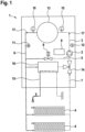
- the condensing heating system 1 shows a condensing heating system 1, which is set up in particular to carry out the method outlined here.
- the condensing heating system 1 has a combustion chamber 13 at the top in the central region. This can be equipped with a primary heat exchanger so that, for example, the heating water entering this boiler is preheated via a gas furnace as required. The heated hot water flows from there (here to the left), whereby the temperature of the heating water in the flow 6 can be determined or recorded by means of a temperature sensor 10.
- the direction of flow 17 is repeatedly characterized by small arrows.
- the heating water then flows past a pressure sensor 11, and then flows on to (distant) heating elements 4, which are shown here in the manner of radiators.There in the radiators 4, the heating water releases its heat and then flows back to the combustion chamber 13.
- a power-modulating pump 2 For this circulation of the heating water is a power-modulating pump 2.
- a volume flow sensor 12 is provided downstream of this power-modulating pump 2, which is also arranged here in the return 7 of the heating water circuit 3.
- another temperature sensor 10 is provided, by means of which the temperature of the heating water can be determined is.
- a bypass 5 is also provided here, which directly connects the flow 6 to the return 7, bypassing the radiators 4 with one another.
- a differential pressure actuable valve 8 is provided in this bypass 5 .
- this figure 1 a so-called gas-fired combi-device is concerned, so that in addition to the pure heating water circulation, another heat exchanger 16 is also traversed in parallel by the heating water, with which an external water line 15 can also be heated. It is thus possible, for example, to heat water for taps, showers or other sanitary facilities with the heating water from this condensing heating system 1 .
- An additional 3-way valve 14 is provided in order to be able to combine these parallel streams with one another again as required and in a controlled manner.
- a regulation and control unit 9 is provided in the outlined housing of the condensing heating system 1 .
- This can, for example, receive or process signals or measured values from the sensors, in particular the temperature sensors 10, the pressure sensor 11 and/or the volume flow sensor 12. It is also possible that this regulation and control unit can influence or control the processes or operating parameters of the combustion chamber 13 , the pump 2 and/or the 3-way valve 14 .
- the regulation and control unit 9 can be set up in such a way that it executes the steps outlined above of the method proposed here. So e.g. B. possible that the detection of the modulation setpoint of the condensing heating system 1 and the combustion chambers 13 is processed there.
- the regulation and control unit 9 acts together with the sensors, it can also determine when the flow through the bypass 5 begins or the (autonomous) differential-pressure-operated valve 8 opens. It is also possible for the regulating and control unit 9 to regulate the operation of the pump 2 when such a flow through the bypass 5 is detected, in particular by maintaining a power output over a predetermined period of time. Likewise, the regulation and control unit 9 can then decide or specify according to predetermined criteria if the power of the pump is to be (gradually) reduced again.
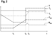
- FIG. 2 shows a diagram to illustrate heating system parameters during the operation of a condensing heating system, in particular during the implementation of the procedure proposed here.
- the diagram shows the flow temperature Tv, return temperature Tr, heating water volume flow V, modulation setpoint Msw and pump setpoint Psw parameters over time t.
- these curves (without a unit and not true to scale) are shown one above the other.
- the reduction in heating water volume flow V explained above can be determined. If the heating water volume flow V reaches a specified limit value, the pump setpoint Psw is (automatically) increased (marked as time t 1 in the diagram), which is accompanied by an immediate pressure increase in the heating water circuit.
- the pressure generated by the pump now also leads to the described pressure difference between flow and return, whereby at the time of the (automatic) opening of the valve that can be actuated by differential pressure (see time t 2 in the diagram), the heating water volume flow V increases significantly or even almost abruptly, the flow temperature Tv falls and the return temperature Tr rises. Therefore, by sensory detection of this characteristic course, it is possible to conclude that flow is starting to flow through the bypass, cf.
- step b) of the method proposed here the setpoint pump value Psw present at time t 2 is kept constant and the setpoint modulation value Msw varies.
- the condensing heating system is again in a stationary state and monitoring of the modulation setpoint Msw or the pump power Psw begins.
- the bypass closes - which depends on the state of the heating system and is no longer shown here - the pump control loop is activated again, with the pump setpoint Psw being lowered in stages if necessary (no longer shown here).
Landscapes
- Engineering & Computer Science (AREA)
- Physics & Mathematics (AREA)
- Thermal Sciences (AREA)
- Chemical & Material Sciences (AREA)
- Combustion & Propulsion (AREA)
- Mechanical Engineering (AREA)
- General Engineering & Computer Science (AREA)
- Computer Hardware Design (AREA)
- Water Supply & Treatment (AREA)
- Fluid Mechanics (AREA)
- Steam Or Hot-Water Central Heating Systems (AREA)
Abstract
Verfahren zum Betrieb einer Brennwert-Heizanlage (1), aufweisend mindestens einen, wenigstens eine Pumpe (2) umfassenden Heizwasserumlauf (3) mit mindestens einem Heizkörper (4) und einem Bypass (5), welcher einen Vorlauf (6) und einen Rücklauf (7) unter Umgehung des mindestens einen Heizkörpers (4) miteinander verbindet, wobei der Bypass (5) mittels eines differenzdruckbetätigbaren Ventils (8) öffen- und schließbar ist, wobei das Verfahren zumindest folgende Schritte umfasst;a) Erfassen eines Modulationssollwertes der Brennwert-Heizanlage (1),b) sensorisches Feststellen einer einsetzenden Durchströmung des Bypasses (5),c) Aufrechtherhalten des Betriebs der Pumpe (2) mit einer vorgegebenen Leistung über einen Zeitraum,d) Reduzieren der Leistung der Pumpe (2), wenn ein vorgegebener Modulationssollwert erreicht ist.Weiter werden eine Brennwert-Heizanlage (1) sowie ein Computerprogramm vorgeschlagen.Method for operating a condensing heating system (1), having at least one heating water circuit (3) comprising at least one pump (2) with at least one heating element (4) and a bypass (5) which has a flow (6) and a return ( 7) bypassing the at least one heating element (4), the bypass (5) being openable and closable by means of a valve (8) that can be actuated by differential pressure, the method comprising at least the following steps;a) detecting a setpoint modulation value of the condensing heating system (1), b) sensory detection of an incipient flow through the bypass (5), c) maintaining the operation of the pump (2) at a predetermined power over a period of time, d) reducing the power of the pump (2) when a predetermined modulation setpoint is reached. Next, a condensing boiler (1) and a computer program are proposed.
Description
Die vorliegende Erfindung betrifft ein Verfahren zum Betrieb einer Brennwert-Heizanlage. Weiterhin wird eine Brennwert-Heizanlage vorgeschlagen sowie ein Computerprogramm, das bei der Ausführung des Verfahrens bei einer Brennwert-Heizanlage unterstützt.The present invention relates to a method for operating a condensing heating system. Furthermore, a condensing heating system is proposed, as well as a computer program that supports the execution of the method in a condensing heating system.
Insbesondere wird hier das technische Gebiet der gasbefeuerten Brennwert-Heizanlagen bzw. Brennwert-Boiler angesprochen. Gasbefeuerte Brennwert-Heizanlagen bzw. Brennwert-Boiler werden insbesondere eingesetzt, Heizungen in Wohnungen, Häusern etc. bedarfsgerecht mit Heizwasser zu versorgen, die durch einen entsprechenden Heißwasserumlauf zu den Heizkörpern geführt werden und dort ihre Wärme abgeben und anschließend wieder zur Brennwert-Heizanlage zurückkommen, um dort erneut aufgewärmt zu werden.In particular, the technical field of gas-fired condensing heating systems or condensing boilers is addressed here. Gas-fired condensing heating systems or condensing boilers are used in particular to supply heating systems in apartments, houses, etc. with heating water as required, which is routed to the radiators by means of a corresponding hot water circulation system, where it gives off its heat and then returns to the condensing heating system. there to be warmed up again.
Derartige Brennwert-Heizanlagen weisen üblicherweise mindestens eine Pumpe auf, die in einem (geschlossenen) Heizwasserumlauf vorgesehen ist. Mit der Pumpe wird Heißwasser durch den Heißwasserumlauf hindurchgepumpt, bevorzugt geregelt je nach der gewünschten Heizleistung der Heizkörper. Der Heißwasserumlauf kann mindestens einen, bevorzugt aber auch mehrere, Heizkörper umfassen. Sobald mehrere Heizkörper, wie bps. Radiatoren, vorgesehen sind, können diese parallel geschalten bzw. von Heizwasser durchströmbar sein.Such condensing heating systems usually have at least one pump which is provided in a (closed) heating water circuit. With the pump, hot water is pumped through the hot water circuit, preferably regulated depending on the desired heat output of the radiator. The hot water circuit can include at least one, but preferably also several, heaters. Once multiple radiators, such as bps. Radiators are provided, they can be connected in parallel or be traversed by heating water.
Die meisten modernen Brennwert-Heizanlagen arbeiten modulierend. Das bedeutet insbesondere, dass sich die Leistung des Boilers bzw. Brenners der Brennwert-Heizanlage während des Betriebes an die tatsächlich erforderliche Wärmeleistung anpasst. Eine solche Anpassung bzw. Regulierung erfolgt bevorzugt stufenlos. Diese Modulation hat insbesondere das Ziel, energiesparend zu arbeiten, denn so genauer die erzeugte Leistung mit der erforderlichen Wärmeleistung übereinstimmt, desto effizienter können die Ressourcen, insbesondere das Brenngas, effizient ausgenutzt werden. So kann vorgesehen werden, dass die Brennwert-Heizanlage einen regulären Modulationssollwert aufweist, bspw. im Bereich von ca. 80 %, der zunächst eingestellt wird, bevor anschließend im Rahmen eines Modulation-Regelprozesses sich die Heizleistung der Brennwert-Heizanlage an die angeforderte Wärmeleistung anpasst.Most modern condensing heating systems work modulating. In particular, this means that the output of the boiler or burner of the condensing heating system adapts to the heat output actually required during operation. Such Adaptation or regulation preferably takes place steplessly. The particular aim of this modulation is to work in an energy-saving manner, because the more precisely the power generated corresponds to the required heat output, the more efficiently the resources, in particular the fuel gas, can be used efficiently. It can be provided that the condensing heating system has a regular modulation setpoint, for example in the range of approx. 80%, which is initially set before the heating output of the condensing heating system is then adapted to the requested heat output as part of a modulation control process .
Im Rahmen des Betriebs einer solchen Brennwert-Heizanlage können Situationen eintreten, die eine signifikante Druckerhöhung im Heizwasserumlauf erzeugen. Eine Hauptursache für eine signifikante Druckerhöhung im Heizwasserumlauf sind sich schließende Heizkörperventile. Mit der signifikanten Druckerhöhung im Heizwasserumlauf ist weiterhin eine Reduzierung des Heizwasservolumenstroms einhergehend. Um die durch das Heizgerät erzeugte thermische Energie an das Heizsystem zu verteilen, kann einer definierter minimaler Heizwasservolumenstrom vorgegeben sein. Wird dieser unterschritten, würde das Heizgerät den Heizbetrieb einstellen. Daher erhöht in dieser Situation der Regelkreis den Sollwert für die Pumpe, um den minimalen Heizwasservolumenstrom nicht zu unterschreiten. Der mit der Pumpe erzeugte Druck kann nicht ohne weiteres über das System "abgebaut" werden, so dass dadurch die Druckdifferenz zwischen Vorlauf und Rücklauf steigt.During the operation of such a condensing heating system, situations can arise that produce a significant increase in pressure in the heating water circuit. A main reason for a significant increase in pressure in the heating water circuit is closing radiator valves. The significant increase in pressure in the heating water circuit is also accompanied by a reduction in the heating water volume flow. In order to distribute the thermal energy generated by the heater to the heating system, a defined minimum heating water volume flow can be specified. If this falls below, the heater would stop heating. Therefore, in this situation, the control circuit increases the set value for the pump so as not to fall below the minimum heating water volume flow. The pressure generated by the pump cannot simply be "reduced" via the system, so that the pressure difference between the flow and return increases as a result.
Um in solchen Situationen Abhilfe zu schaffen, ist bekannt, einen Bypass vorzusehen, welcher einen Vorlauf des Heizwassers hin zu den Heizkörpern und einen Rücklauf für das Heizwasser unter Umgehung des mindestens einen Heizkörpers miteinander verbindet. Daher kann Heizwasser bei geöffnetem Bypass ohne Durchströmung eines Heizkörpers unmittelbar vom Vorlauf hin zum Rücklauf strömen. Weiter ist bekannt, dass in diesem Bypass ein differenzdruckbetätigbares Ventil vorgesehen ist, welches selbstständig öffnen und schließen kann, in Abhängigkeit der Druckdifferenz im Bypass stromaufwärts und stromabwärts des Ventils. Hierfür kann das Ventil mit einer Feder und einer vorgegebenen Federkraft bzw. Federkennlinie ausgestattet sein, sodass bei einem vorgegebenen Differenzdruck das Ventil öffnet. Liegt die Differenz darunter, bleibt das Ventil verschlossen und damit der Bypass undurchströmbar. Ein solch erhöhter Differenzdruck kann sich gerade bei der vorstehend beschriebenen Situation einstellen, sodass in diesem Fall der Bypass öffnet und weiterer Druckanstieg vermieden wird.In order to remedy such situations, it is known to provide a bypass which connects a flow of the heating water to the radiators and a return for the heating water, bypassing the at least one radiator. Therefore, when the bypass is open, heating water can flow directly from the flow to the return without flowing through a radiator. It is also known that a differential-pressure-actuable valve is provided in this bypass, which valve can be opened and closed automatically can close, depending on the pressure difference in the bypass upstream and downstream of the valve. For this purpose, the valve can be equipped with a spring and a predetermined spring force or spring characteristic, so that the valve opens at a predetermined differential pressure. If the difference is lower, the valve remains closed and the bypass cannot flow through. Such an increased differential pressure can occur precisely in the situation described above, so that in this case the bypass opens and a further increase in pressure is avoided.
Das Vorsehen des Bypasses hat sich insbesondere als geeignet herausgestellt, wenn zu geringe Heizwasserumläufe bzw. zu hohe Differenzdrücke entstehen könnten, da hierdurch insbesondere die Vorlauftemperaturen bis hin zum Sieden ansteigen könnten und/oder deutlich spürbare bzw. hörbare Vibrationen an den Thermostatventilen entstehen könnten.The provision of the bypass has proven to be particularly suitable if the heating water circulation is too low or the differential pressures are too high, since this could cause the flow temperatures to rise to the point of boiling and/or clearly noticeable or audible vibrations on the thermostatic valves.
Bei üblichen System-Boilern sowie auch bei sogenannten Combi-Boilern, also Brennwert-Heizanlagen, die neben Heizwasser auch Verbrauchswasser, bspw. für Duschen oder andere Anwendungen sanitärer Art bereitstellen bzw. mit aufheizen, können weitere technische Probleme aufweisen.With conventional system boilers and also with so-called combi-boilers, i.e. condensing heating systems which, in addition to heating water, also provide or heat up service water, e.g. for showers or other sanitary applications, can have further technical problems.
So ist es bisher nicht möglich, bedarfsgerecht bzw. mit variabler Pumpenleistung auf ein Öffnen des Bypasses zu reagieren, wodurch einige Nachteile zur Einhaltung der Sicherheit hinzunehmen sind. Beispielsweise ist es erforderlich, mit dem Öffnen des Bypasses und beim Beimischen vom warmen Vorlaufwasser zum kalten Rücklaufwasser die Rücklauftemperatur anzuheben, wodurch die in einem Brennwert-Boiler vorgesehene Auskondensierungen von Wasserdampf im Abgas reduziert wird und demzufolge der Wirkungsgrad temporär vermindert wird. In Heizgeräten mit Bypass gemäß dem Stand der Technik werden die Pumpen weitgehend ungeregelt bzw. in Stufen geregelt betrieben, was zum einen zu einem erhöhten elektrischen Verbrauch führt und zum anderen dazu, dass der Bypass entsprechend dem ungeregelten Pumpenbetrieb häufig permanent geöffnet ist. Zudem emittieren Pumpen, insbesondere bei hohen Drehzahlen, störende Geräusche.So far it has not been possible to react to an opening of the bypass as needed or with variable pump performance, which means that some disadvantages in maintaining safety have to be accepted. For example, it is necessary to raise the return temperature when the bypass is opened and when the warm flow water is mixed with the cold return water. In heaters with a bypass according to the prior art, the pumps are operated largely unregulated or regulated in stages, which on the one hand leads to increased electrical consumption and on the other hand to the bypass being damaged accordingly is often permanently open during unregulated pump operation. Pumps also emit annoying noises, especially at high speeds.
Aufgabe der vorliegenden Erfindung ist es, die mit Bezug auf den Stand der Technik geschilderten Probleme zumindest teilweise zu lösen. Insbesondere soll ein Verfahren zum Betrieb einer Brennwert-Heizanlage angegeben werden, welches schonender und/oder energieeffizienter arbeitet. Weiterhin sollen eine hierfür geeignete Brennwert-Heizanlage, ein Computerprogramm sowie ein computerlesbares Medium vorgeschlagen werden.The object of the present invention is to at least partially solve the problems described with reference to the prior art. In particular, a method for operating a condensing heating system is to be specified, which works more gently and/or more energy-efficiently. Furthermore, a condensing boiler suitable for this purpose, a computer program and a computer-readable medium are to be proposed.
Diese Aufgaben werden gelöst mit dem Verfahren zum Betrieb einer Brennwert-Heizanlage nach Anspruch 1, einer Brennwert-Heizanlage nach Anspruch 7, einem Computerprogramm nach Anspruch 9 und einem computerlesbaren Medium nach Anspruch 10. Vorteilhafte Weiterbildungen sind in den abhängigen Ansprüchen angegeben. Es ist darauf hinzuweisen, dass die in den Ansprüchen aufgeführten Merkmale in beliebiger, technologisch sinnvoller Weise miteinander kombiniert werden können, und weitere Ausgestaltungen der Erfindung aufzeigen. Die Beschreibung, insbesondere im Zusammenhang mit den Figuren, erläutert die Erfindung und gibt weitere Ausführungsbeispiele und Präzisierungen an.These objects are achieved with the method for operating a condensing heating system according to
Das hier vorgeschlagene Betriebsverfahren kann in einer Brennwert-Heizanlage ausgeführt werden, welche mindestens einen, wenigstens eine Pumpe umfassenden Heizwasserumlauf mit mindestens einem Heizkörper und einem Bypass, welcher einen Vorlauf und einen Rücklauf unter Umgehung des mindestens einen Heizkörpers miteinander verbindet, aufweist. Der Bypass ist dabei mittels eines differenzdruckbetätigbaren Ventils öffen- und schließbar. Die Brennwert-Heizanlage ist insbesondere dazu eingerichtet, im Heizwasserumlauf befindliches Wasser mittels der Pumpe umzuwälzen, sodass das sogenannte Heizwasser im Regelbetrieb den mindestens einen Heizkörper durchströmt. Weiter hat die Brennwert-Heizanlage insbesondere einen sogenannten gasbefeuerten Brennwert-Boiler, wo dort hingeführtes Heizwasser mittels einer Gasfeuerung erhitzt wird. Das so erhitzte Heizwasser gelangt über den Vorlauf mit einer erhöhten Temperatur hin zu dem Heizkörper, durchströmt diesen, gibt dabei einen Großteil seiner Wärme ab und wird dann weiter zurück zu der Brennkammer geführt. Wie bereits erläutert, können mehrere Heizkörper vorgesehen sein, die bevorzugt parallele Wasserströmungspfade ausbilden.The operating method proposed here can be carried out in a condensing heating system which has at least one heating water circuit comprising at least one pump with at least one radiator and a bypass which connects a flow and a return, bypassing the at least one radiator. The bypass can be opened and closed by means of a valve that can be actuated by differential pressure. The condensing heating system is set up in particular to circulate the water in the heating water circuit by means of the pump, so that the so-called heating water flows through the at least one radiator in regular operation. Furthermore, the condensing heating system has, in particular, a so-called gas-fired condensing boiler, where the heating water fed there is heated by means of a gas furnace. The heating water thus heated reaches the radiator via the flow at an increased temperature, flows through it, gives off a large part of its heat and is then routed back to the combustion chamber. As already explained, several heating elements can be provided, which preferably form parallel water flow paths.
Das Verfahren umfasst dabei zumindest folgende Schritte:
- a) Erfassen eines Modulationssollwertes der Brennwert-Heizanlage,
- b) sensorisches Feststellen einer einsetzenden Durchströmung des Bypasses,
- c) Aufrechterhalten des Betriebs der Pumpe mit einer vorgegebenen Leistung über einen Zeitraum,
- d) Reduzieren der Leistung der Pumpe, wenn ein vorgegebener Modulationssollwert erreicht ist.
- a) detection of a modulation target value of the condensing heating system,
- b) sensory detection of an incipient flow through the bypass,
- c) maintaining the operation of the pump at a specified power over a period of time,
- d) reducing the power of the pump when a predetermined modulation setpoint is reached.
Es ist möglich, dass die hier aufgeführten Schritte sequenziell bzw. nacheinander, in der hier angegebenen Reihenfolge a), b), c), d) ablaufen. Es ist aber auch möglich, dass sich die Schritte zumindest teilweise zeitlich überlagern.It is possible that the steps listed here take place sequentially or one after the other, in the order given here a), b), c), d). However, it is also possible for the steps to overlap at least in part in terms of time.
So ist bspw. möglich, dass Schritt a) intermittierend oder kontinuierlich während des gesamten Verfahrens ausgeführt wird, also der Modulationssollwert praktisch kontinuierlich erfasst wird. Insbesondere findet Schritt a) während des sogenannten Regelbetriebs statt, also im Zustand, wenn der Bypass geschlossen ist.For example, it is possible for step a) to be carried out intermittently or continuously throughout the entire method, ie the modulation target value is recorded practically continuously. In particular, step a) takes place during so-called regular operation, ie in the state when the bypass is closed.
In Schritt b) wird nun sensorisch festgestellt, wenn eine Bypassströmung einsetzt, also wenn das differenzdruckbetätigbare Ventil öffnet und damit Heizwasser durch den Bypass hindurchströmen kann. Das sensorische Feststellen umfasst insbesondere die Erkennung von Parametern bzw. Verlaufsparametern des Betriebes der Brennwert-Heizanlage, die charakteristisch für den Öffenvorgang des differenzdruckbetätigbaren Ventils bzw. des Bypasses sind. Insbesondere sind hierfür Grenzwerte bzw. Toleranzschwellen vorgesehen, deren Erreichen bzw. Über-/Unterschreiten zur unmittelbaren Feststellung einer einsetzenden Durchströmung des Bypasses zur Folge hat. Von besonderer Bedeutung kann sein, dass das sensorische Feststellen sehr schnell erfolgt, bspw. innerhalb weniger Sekunden, wie bspw. binnen max. 30 Sekunden oder sogar binnen max. 10 Sekunden. Insbesondere ist möglich, dass die sensorische Feststellung bereits vorliegt, bevor der vollständige Durchsatz durch den Bypass erreicht ist, den das differenzdruckbetätigbare Ventil maximal freigeben kann.In step b), it is now determined by sensors when a bypass flow begins, ie when the valve that can be actuated by differential pressure opens and heating water can therefore flow through the bypass. The sensory determination includes, in particular, the detection of parameters or progression parameters of the operation of the condensing heating system that are characteristic of the opening process of the valve or the bypass that can be actuated by differential pressure are. In particular, limit values or tolerance thresholds are provided for this purpose, and if they are reached or exceeded or fallen below, this results in the direct determination of an incipient flow through the bypass. It can be of particular importance that the sensory determination takes place very quickly, for example within a few seconds, for example within a maximum of 30 seconds or even within a maximum of 10 seconds. In particular, it is possible that the sensory determination is already present before the full throughput has been reached through the bypass, which the valve that can be actuated by differential pressure can maximally release.
Bevorzugt unmittelbar im Anschluss an Schritt b) wird die Pumpenleistung der Pumpe im Heizwasserumlauf stabilisiert bzw. aufrechterhalten. Das kann insbesondere bedeuten, dass die üblicherweise leistungsmodulierte Pumpe im Rahmen des Schritt c) keine variierende Leistung aufweist, sondern mit einer konstanten Leistung betrieben wird. Diese Leistung kann insbesondere der entsprechen, die gerade zum Zeitpunkt der Feststellung der einsetzenden Durchströmung des Bypasses vorliegt. Es ist auch möglich, dass die vorgegebene Leistung einer gegenüber dem Regelbetrieb erhöhte Leistung ist, bspw. bei ca. 90 % oder sogar ca. 95 % liegt. Das Aufrechterhalten dieser vorgegebenen Leistung hält insbesondere so lange an, bis der Gesamtprozess wieder stabilisiert ist. Der Regelkreis der Pumpe ist bzw. bleibt so lange deaktiviert, wie der Bypass geöffnet ist. Das Schließen des Bypasses hängt vom Zustand des Heizsystems ab.The pump performance of the pump in the heating water circuit is preferably stabilized or maintained immediately after step b). This can mean in particular that the usually power-modulated pump in step c) does not have a varying power but is operated with a constant power. In particular, this output can correspond to that which is present at the moment when the onset of flow through the bypass is determined. It is also possible that the specified power is a power that is increased compared to normal operation, for example at approximately 90% or even approximately 95%. Maintaining this predetermined performance lasts in particular until the overall process is stabilized again. The control circuit of the pump is or remains deactivated as long as the bypass is open. Closing the bypass depends on the state of the heating system.
Ist der Prozess stabilisiert, was bspw. auch sensorisch anhand diverser Parameter oder Verlaufsparameter der Brennwert-Heizanlage erkannt bzw. feststellbar ist, kann Schritt d) initiiert werden. Dabei wird die Leistung der Pumpe dann reduziert, wenn ein vorgegebener Modulationssollwert erreicht ist. Der vorgegebene Modulationssollwert kann ein vorbestimmter Wert sein, es ist aber auch möglich, dass dieser aus einer parallelen Messung gemäß Schritt a) angepasst ermittelt und vorbestimmt wird.If the process is stabilized, which can also be detected or ascertained, for example, by sensors using various parameters or progression parameters of the condensing heating system, step d) can be initiated. The power of the pump is then reduced when a predetermined modulation target value is reached. The predefined modulation target value can be a predetermined value, but it is also possible for this value to be determined and predetermined from a parallel measurement in accordance with step a).
Bevorzugt ist, dass in Schritt d) ein schrittweises Reduzieren der Leistung der Pumpe erfolgt, bis das differenzdruckbetätigbare Ventil schließt. Insbesondere kann eine Routine hinterlegt werden, welche, ggf. in Abhängigkeit der aktuellen Betriebssituation der Brennwert-Heizanlage die Schritte der Reduzierung (Größe und/oder Zeiträume) vorgibt. Die Reduzierung der Leistung der Pumpe führt aber erneut zu einem Angleichen der Druckverhältnisse insgesamt im Heizwasserumlauf, sodass bei einer erfolgreichen Stabilisierung das differenzdruckbetätigbare Ventil automatisch schließt und damit eine Durchströmung des Bypasses nicht mehr stattfindet.It is preferred that in step d) the output of the pump is reduced step by step until the valve that can be actuated by differential pressure closes. In particular, a routine can be stored which, possibly depending on the current operating situation of the condensing heating system, specifies the reduction steps (magnitude and/or periods of time). However, the reduction in the output of the pump again leads to an equalization of the overall pressure conditions in the heating water circuit, so that if stabilization is successful, the valve that can be actuated by differential pressure closes automatically and flow through the bypass no longer takes place.
Es ist möglich, dass in Schritt b) sensorisch das Erreichen eines Grenzwertes mittels eines Parameters aus der folgenden Gruppe festgestellt wird: Heizwasservolumenstrom, Heizwassersystemdruck, Heizwassertemperatur im Rücklauf. Insbesondere können Mittel und/oder Maßnahmen vorgesehen sein, anhand derer ein aktueller Heizwasservolumenstrom, ein aktueller Heizwassersystemdruck und/oder eine aktuelle Heizwassertemperatur im Rücklauf des Heizwasserumlaufs ermittelt werden. Auch hier ist möglich, diese aktuell sensorisch ermittelten Parameter mit einem vorgegebenen (fixen bzw. variabel anpassbaren) Grenzwert zu vergleichen. So ist bspw. möglich, dass auf ein Öffnen des Bypasses geschlossen wird, wenn der aktuelle Heizwasservolumenstrom in einem vorbestimmten Bereich, bspw. im Rücklauf des Heizwasserumlaufs, einen vorgegebenen Grenzwert für den Heizwasservolumenstrom erreicht bzw. überschreitet. Ebenso ist möglich, dass der Heizwassersystemdruck im Vorlauf unter einen vorgebbaren Grenzwert fällt bzw. im Rücklauf über einen vorgegebenen Grenzwert steigt, um auf die einsetzende Durchströmung des Bypasses zu schließen. Ebenso ist möglich, eine Temperaturerhöhung im Bereich des Rücklaufs anhand eines vorgegebenen Grenzwertes zu detektieren.It is possible that in step b) the reaching of a limit value is determined by sensors using a parameter from the following group: heating water volume flow, heating water system pressure, heating water temperature in the return. In particular, means and/or measures can be provided by means of which a current heating water volume flow, a current heating water system pressure and/or a current heating water temperature in the return of the heating water circuit can be determined. Here, too, it is possible to compare these currently sensor-determined parameters with a predetermined (fixed or variably adaptable) limit value. For example, it is possible to conclude that the bypass is opening if the current heating water volume flow in a predetermined area, e.g. in the return of the heating water circuit, reaches or exceeds a predetermined limit value for the heating water volume flow. It is also possible for the heating water system pressure to fall below a specified limit value in the supply line or to rise above a specified limit value in the return line in order to conclude that flow through the bypass is starting. It is also possible to detect a temperature increase in the return flow using a specified limit value.
Doch nicht nur konkrete Werte, sondern ggf. auch zeitliche Verlaufsparameter können im Rahmen des Schritts b) überprüft werden. So ist es möglich, sensorisch das Erreichen eines Grenzwertes mindestens eines Verlaufsparameters aus der folgenden Gruppe festzustellen: Heizwasservolumenstromänderung, Heizwassersystemdruckänderung, Heizwassertemperaturänderung im Rücklauf. Folglich wird hier eine zeitliche Bewertung (Änderungsgeschwindigkeit) berücksichtigt.However, not only concrete values, but possibly also parameters over time can be checked in the context of step b). It is thus possible to use sensors to detect when a limit value has been reached for at least one course parameter from the following group determine: heating water volume flow change, heating water system pressure change, heating water temperature change in the return. Consequently, a temporal evaluation (speed of change) is taken into account here.
Offensichtlich ist, dass Parameter und Verlaufsparameter auch miteinander bzw. wechselweise hierfür herangezogen werden können.It is obvious that parameters and course parameters can also be used together or alternately for this purpose.
Es ist möglich, dass ein vor Schritt b) vorliegender Modulationssollwert etwa dem vorgegebenen Modulationssollwert in Schritt d) entspricht. So kann bspw. der unmittelbar vor Schritt b) in Schritt a) ermittelte Modulationssollwert gespeichert und dann als Vorgabe für den Modulationssollwert zum Start der Reduzierung der Leistung der Pumpe gemäß Schritt d) angegeben werden.It is possible that a setpoint modulation value present before step b) approximately corresponds to the setpoint setpoint modulation specified in step d). For example, the setpoint modulation value determined immediately before step b) in step a) can be stored and then specified as a specification for the setpoint modulation value at the start of the reduction in the power of the pump in accordance with step d).
Es ist weiterhin möglich, dass nach Schritt d) ein Betrieb der Pumpe mit regulärer Leistung wieder erfolgt.It is also possible that, after step d), the pump is again operated at regular power.
Der Vorteil der Erfindung ist insbesondere eine Pumpenregelung, die das Öffnen des Bypasses auf ein Minimum reduziert. Sie nutzt eine Volumenstromregelung durch eine entsprechende Pumpe und Sensorik und umfasst eine Erkennung für die Öffnung des Bypasses, die Überwachung und Stabilisierung des dabei vorliegenden Gerätebetriebes und die kontrollierte Rückkehr zum regulären Pumpenbetrieb bei steigender Wärmeanforderung und damit einhergehendem Schließen des Bypasses.The advantage of the invention is in particular a pump control that reduces the opening of the bypass to a minimum. It uses a volume flow control by means of a corresponding pump and sensors and includes a detection for the opening of the bypass, the monitoring and stabilization of the existing device operation and the controlled return to regular pump operation in the event of an increasing heat requirement and the associated closing of the bypass.
Solange der Bypass geschlossen ist und der gesamte Heizwasservolumenstrom in die Heizkörper fließt, handelt es sich aus regelungstechnischer Sicht um ein lineares System. Dementsprechend können für eine Volumenstromregelung bis zum Öffnen des Bypasses Regelungsalgorithmen für lineare Systeme eingesetzt werden.As long as the bypass is closed and the entire heating water volume flow flows into the radiators, the system is linear from a control point of view. Accordingly, control algorithms for linear systems can be used for volume flow control until the bypass is opened.
Das Öffnen des Bypasses stellt aus regelungstechnischer Sicht eine Nichtlinearität dar und zeichnet sich insbesondere durch einen sprunghaften Anstieg des Heizwasservolumenstroms ab. Dieser sprunghafte Anstieg ist mit der entsprechenden Sensorik direkt oder indirekt zu ermitteln. Ein zweiter plausibilisierender Indikator für das Öffnen des Bypasses ist der Temperaturanstieg des Heizwassers im Rücklauf, weil dieses Heizwasser mit aus dem Vorlauf über den Bypass einströmendem Heizwasser deutlich höherer Temperatur gemischt wird. Der Temperaturanstieg kann im Rahmen einer definierten Zeitspanne sowie im Beharrungszustand bezüglich einer gemessenen Temperatur und der aktuellen Modulation sowie der Pumpenleistung einen Schwellwert überschreiten oder einen Erfahrungswert erreichen.From a control point of view, opening the bypass represents a non-linearity and is characterized in particular by a sudden increase in the heating water volume flow. This sudden increase can be determined directly or indirectly with the appropriate sensors. A second plausibility-checking indicator for the opening of the bypass is the rise in temperature of the heating water in the return, because this heating water is mixed with the heating water flowing in from the flow via the bypass at a significantly higher temperature. The temperature increase can exceed a threshold value or reach an empirical value within a defined period of time and in the steady state with regard to a measured temperature and the current modulation as well as the pump output.
Werden insbesondere diese beiden Zustände (Volumenstromsprung und Rücklauftemperaturanstieg) in einer definierten zeitlichen Abfolge erkannt, ist von einem geöffneten Bypass auszugehen. Es ist auch möglich, ggf. alternativ anstelle des Volumenstromanstiegs auch eine (sprunghafte) Änderung des Heizwassersystemdrucks (fallendem Vorlauf, steigendem Rücklauf) zur Feststellung einer einsetzenden Durchströmung des Bypasses heranzuziehen.If these two states in particular (volume flow jump and return temperature rise) are detected in a defined time sequence, an open bypass can be assumed. Alternatively, it is also possible to use a (sudden) change in the heating water system pressure (falling flow, rising return) instead of the increase in volume flow to determine when flow through the bypass is starting.
Nach Erkennen des Öffnens des Bypasses und zur Stabilisierung des Prozesses wird im weiteren Verlauf die Leistung der Pumpe konstant auf dem vorgegebenen Leistungsniveau gehalten, das zum Öffnen des Bypasses geführt hat. Insbesondere kann dies auch erfolgen, um ein sogenanntes "Toggeln", also ein stetig sich wiederholendes Öffnen und Schließen des Bypasses, zu verhindern.After detection of the opening of the bypass and to stabilize the process, the output of the pump is kept constant at the specified output level that led to the opening of the bypass. In particular, this can also be done in order to prevent so-called "toggling", ie a continuously repeated opening and closing of the bypass.
Weiterhin kann der Modulationssollwert der Brennwert-Heizanlage auf einen Anstieg überwacht werden, der dem thermischen Leistungsbedarf vor dem Öffnen des Bypasses entspricht. Wird dieser Wert erreicht, kann die bisher konstant gehaltene Pumpenleistung wieder gesenkt werden.Furthermore, the modulation setpoint of the condensing heating system can be monitored for an increase that corresponds to the thermal power requirement before the bypass is opened. If this value is reached, the previously constant pump output can be reduced again.
In der letzten Phase wird die Leistung der Pumpe so lange schrittweise reduziert, bis bevorzugt der Regel-Sollwert der Pumpenleistung erreicht ist. Hierbei kann dann davon ausgegangen werden, dass sich der Bypass nun wieder schließt.In the last phase, the power of the pump is reduced step by step until the control setpoint of the pump power is preferably reached. It can then be assumed that the bypass now closes again.
Da sich zuvor der Sollwert des thermischen Leistungsbedarfs erhöht hat, ist davon auszugehen, dass Ventile an den Heizkörpern bzw. Radiatoren wieder geöffnet sind, wodurch der zuvor hohe hydraulische Druckverlust, der zum Öffnen des Bypasses geführt hat, nun geringer ist und durch eine Pumpenregelung auf geringem Leistungsniveau ohne ein Öffnen des Bypasses möglich ist.Since the target value of the thermal power requirement had previously increased, it can be assumed that valves on the heaters or radiators are open again, which means that the previously high hydraulic pressure loss that led to the opening of the bypass is now lower and is increased by pump control low performance level is possible without opening the bypass.
Gemäß einem weiteren Aspekt wird eine Brennwert-Heizanlage vorgeschlagen, welche mindestens einen, wenigstens eine Pumpe umfassenden Heizwasserumlauf mit mindestens einem Heizkörper und einem Bypass aufweist. Der Bypass verbindet einen Vorlauf und einen Rücklauf unter Umgehung des mindestens einen Heizkörpers und ist mittels eines differenzdruckbetätigbaren Ventils öffen- und schließbar. Weiter sind Mittel vorgesehen, die so eingerichtet sind, dass diese die Schritte des hier beschriebenen Verfahrens ausführen können. Diese Mittel können bspw. eine Regel- und Steuereinheit sowie mindestens ein Sensor sein. Als Sensoren, die insbesondere im Rahmen des Schritts b) eingesetzt werden, sind ausgewählt aus der Gruppe Temperatursensor, Drucksensor, Volumenstromsensor.According to a further aspect, a condensing heating system is proposed, which has at least one heating water circuit comprising at least one pump with at least one radiator and a bypass. The bypass connects a supply line and a return line, bypassing the at least one heating element, and can be opened and closed by means of a valve that can be actuated by differential pressure. Means are also provided which are set up in such a way that they can carry out the steps of the method described here. These means can be, for example, a regulation and control unit and at least one sensor. Sensors used in particular in step b) are selected from the group consisting of temperature sensors, pressure sensors and volumetric flow sensors.
Weiter wird noch ein Computerprogramm vorgeschlagen, welches Befehle umfasst, die bewirken, dass die Brennwert-Heizanlage der vorstehend genannten Art die Schritte des Verfahrens der hier offenbarten Weise ausführen. Schließlich kann noch ein computerlesbares Medium vorgesehen sein, auf dem das hier genannte Computerprogramm gespeichert ist.Furthermore, a computer program is also proposed, which comprises commands which cause the condensing boiler of the type mentioned above to carry out the steps of the method in the manner disclosed here. Finally, a computer-readable medium can also be provided, on which the computer program mentioned here is stored.
Die Erfindung sowie das technische Umfeld werden nachfolgend unter Bezugnahme einer Figur näher erläutert. Es ist darauf hinzuweisen, dass diese Figur schematischer Natur ist und die Erfindung insgesamt nicht beschränken soll. Es zeigen:
- Fig.1:
- den Aufbau einer Brennwert-Heizanlage, und
- Fig.2:
- ein Diagramm zur Veranschaulichung von Heizanlagenparameter während des Betriebes.
- Fig.1:
- the construction of a condensing heating system, and
- Fig.2:
- a diagram to illustrate heating system parameters during operation.
Weiter ist hier auch ein Bypass 5 vorgesehen, der direkt den Vorlauf 6 mit dem Rücklauf 7 unter Umgehung der Heizkörper 4 miteinander verbindet. In diesem Bypass 5 ist ein differenzdruckbetätigbares Ventil 8 vorgesehen. Weiter ist anzumerken, dass diese
Zudem ist in dem skizzierten Gehäuse der Brennwert-Heizanlage 1 eine Regel- und Steuereinheit 9 vorgesehen. Diese kann bspw. Signale bzw. Messwerte von den Sensoren, insbesondere den Temperatursensoren 10, dem Drucksensor 11 und/oder dem Volumenstromsensor 12 empfangen bzw. verarbeiten. Weiter ist möglich, dass diese Regel- und Steuereinheit auf die Prozesse bzw. Betriebsparameter der Brennkammer 13, der Pumpe 2 und/oder des 3-Wege-Ventils 14 beeinflussen bzw. kontrollieren kann. Die Regel- und Steuereinheit 9 kann so eingerichtet sein, dass diese die zuvor skizzierten Schritte des hier vorgeschlagenen Verfahrens ausführt. So ist z. B. möglich, dass die Erfassung des Modulationssollwertes der Brennwert-Heizanlage 1 bzw. der Brennkammern 13 dort verarbeitet wird. Da die Regel- und Steuereinheit 9 mit den Sensoren zusammen agiert, kann diese auch feststellen, wenn die Durchströmung des Bypasses 5 einsetzt bzw. das (autarke) differenzdruckbetätigbare Ventil 8 öffnet. Weiter ist es der Regel- und Steuereinheit 9 möglich, bei Feststellung einer solchen Durchströmung des Bypasses 5 den Betrieb der Pumpe 2 zu regulieren, insbesondere, indem diese eine Leistung über einen vorgegebenen Zeitraum aufrechterhält. Ebenso kann die Regel- und Steuereinheit 9 dann nach vorgegebenen Kriterien entscheiden bzw. vorgeben, wenn die Leistung der Pumpe (schrittweise) wieder reduziert werden soll.In addition, a regulation and
In einer ersten Phase des Betriebes kann die eingangs erläuterte Reduzierung des Heizwasservolumenstroms V festgestellt werden. Erreicht der Heizwasservolumenstrom V einen vorgegebenen Grenzwert, wird (automatisch) der Pumpensollwert Psw angehoben (im Diagramm als Zeitpunkt t1 gekennzeichnet), was mit einer unmittelbaren Druckerhöhung im Heizwasserumlauf einhergeht. Der mit der Pumpe erzeugte Druck führt nunmehr auch zu der beschriebenen Druckdifferenz zwischen Vorlauf und Rücklauf, wobei sich zum Zeitpunkt des (automatischen) Öffnens des differenzdruckbetätigbaren Ventils (siehe Zeitpunkt t2 im Diagramm) der Heizwasservolumenstrom V signifikant oder gar fast sprunghaft ansteigt, die Vorlauftemperatur Tv abfällt und die Rücklauftemperatur Tr ansteigt. Daher kann durch sensorisches Erfassen dieses charakteristischen Verlaufs auf ein einsetzendes Durchströmen des Bypasses geschlossen werden, vgl. Schritt b) des hier vorgeschlagenen Verfahrens. Nun wird für eine weitere Phase der zum Zeitpunkt t2 vorliegende Pumpensollwert Psw konstant gehalten und der Modulationssollwert Msw variiert. Insbesondere wenn die Vorlauftemperatur Tv wieder einen gewünschten (konstanten) Wert erreicht und/oder der Modulationssollwert Msw wieder einen gewünschten (konstanten) Wert erreicht (siehe Zeitpunkt t3 im Diagramm), befindet sich die Brennwert-Heizanlage wieder in einem stationären Zustand und die Überwachung des Modulationssollwertes Msw bzw. der Pumpenleistung Psw beginnt. Wenn der Bypass schließt - was vom Zustand des Heizsystems abhängt und hier nicht mehr veranschaulicht ist - wird der Regelkreis der Pumpe wieder aktiviert, wobei ggf. stufenweise der Pumpensollwert Psw gesenkt wird (hier nicht mehr dargestellt).In a first phase of operation, the reduction in heating water volume flow V explained above can be determined. If the heating water volume flow V reaches a specified limit value, the pump setpoint Psw is (automatically) increased (marked as time t 1 in the diagram), which is accompanied by an immediate pressure increase in the heating water circuit. The pressure generated by the pump now also leads to the described pressure difference between flow and return, whereby at the time of the (automatic) opening of the valve that can be actuated by differential pressure (see time t 2 in the diagram), the heating water volume flow V increases significantly or even almost abruptly, the flow temperature Tv falls and the return temperature Tr rises. Therefore, by sensory detection of this characteristic course, it is possible to conclude that flow is starting to flow through the bypass, cf. step b) of the method proposed here. Now, for a further phase, the setpoint pump value Psw present at time t 2 is kept constant and the setpoint modulation value Msw varies. In particular, when the flow temperature Tv reaches a desired (constant) value again and/or the modulation setpoint Msw reaches a desired (constant) value again (see point in time t 3 in the diagram), the condensing heating system is again in a stationary state and monitoring of the modulation setpoint Msw or the pump power Psw begins. When the bypass closes - which depends on the state of the heating system and is no longer shown here - the pump control loop is activated again, with the pump setpoint Psw being lowered in stages if necessary (no longer shown here).
- 11
- Brennwert-HeizanlageCondensing heating system
- 22
- Pumpepump
- 33
- Heizwasserumlaufheating water circulation
- 44
- Heizkörperradiator
- 55
- Bypassbypass
- 66
- Vorlaufleader
- 77
- Rücklaufreturn
- 88th
- differenzdruckbetätigbares Ventildifferential pressure operated valve
- 99
- Regel- und SteuereinheitRegulating and control unit
- 1010
- Temperatursensortemperature sensor
- 1111
- Drucksensorpressure sensor
- 1212
- Volumenstromsensorflow rate sensor
- 1313
- Brennkammercombustion chamber
- 1414
- Dreiwegeventilthree-way valve
- 1515
- Wasserleitungwater pipe
- 1616
- Wärmetauscherheat exchanger
- 1717
- Strömungsrichtungflow direction
- Tvtv
- Vorlauftemperaturflow temperature
- TrTr
- Rücklauftemperaturreturn temperature
- VV
- Heizwasservolumenstromheating water flow rate
- MswVAT
- Modulationssollwertmodulation setpoint
- PswPSW
- Pumpensollwertpump setpoint
- tt
- ZeitTime
Claims (10)
Applications Claiming Priority (1)
| Application Number | Priority Date | Filing Date | Title |
|---|---|---|---|
| DE102021121888.8A DE102021121888A1 (en) | 2021-08-24 | 2021-08-24 | Method for operating a condensing heating system, condensing heating system and computer program |
Publications (1)
| Publication Number | Publication Date |
|---|---|
| EP4141334A1 true EP4141334A1 (en) | 2023-03-01 |
Family
ID=83115524
Family Applications (1)
| Application Number | Title | Priority Date | Filing Date |
|---|---|---|---|
| EP22191495.5A Pending EP4141334A1 (en) | 2021-08-24 | 2022-08-22 | Method for operating a heater, computer program, storage medium, regulation and control device, heater and use of a signal |
Country Status (2)
| Country | Link |
|---|---|
| EP (1) | EP4141334A1 (en) |
| DE (1) | DE102021121888A1 (en) |
Families Citing this family (1)
| Publication number | Priority date | Publication date | Assignee | Title |
|---|---|---|---|---|
| DE102022107592A1 (en) | 2022-03-30 | 2023-10-05 | Viessmann Climate Solutions Se | Method for controlling a heating system, heating system and control device |
Citations (4)
| Publication number | Priority date | Publication date | Assignee | Title |
|---|---|---|---|---|
| DE4041183A1 (en) * | 1990-12-21 | 1992-06-25 | Buderus Heiztechnik Gmbh | Heating system with thermostatically controller radiator - is heated by geyser and has relief line controlled by magnetic valve |
| GB2301430A (en) * | 1995-05-06 | 1996-12-04 | Nicholas Julian Jan F Macphail | Central heating control system |
| EP1160515A2 (en) * | 2000-06-03 | 2001-12-05 | Robert Bosch Gmbh | Heating installation with at least two heating circuits |
| DE102012003502A1 (en) * | 2011-11-18 | 2013-05-23 | Vaillant Gmbh | Method for operating heating system of gas condensing boiler plant, involves increasing pump speed if calculated differential pressure is lower than intermediate threshold value, upper threshold value and lower threshold value |
Family Cites Families (2)
| Publication number | Priority date | Publication date | Assignee | Title |
|---|---|---|---|---|
| AT397854B (en) | 1992-02-18 | 1994-07-25 | Vaillant Gmbh | Method for controlling a boiler |
| DE102017010891A1 (en) | 2017-11-26 | 2019-05-29 | novaTec Elektronik GmbH | Differential pressure sensing system, piping unit, use of a piping unit, heat distribution system, use of a heat distribution system and method |
-
2021
- 2021-08-24 DE DE102021121888.8A patent/DE102021121888A1/en active Pending
-
2022
- 2022-08-22 EP EP22191495.5A patent/EP4141334A1/en active Pending
Patent Citations (4)
| Publication number | Priority date | Publication date | Assignee | Title |
|---|---|---|---|---|
| DE4041183A1 (en) * | 1990-12-21 | 1992-06-25 | Buderus Heiztechnik Gmbh | Heating system with thermostatically controller radiator - is heated by geyser and has relief line controlled by magnetic valve |
| GB2301430A (en) * | 1995-05-06 | 1996-12-04 | Nicholas Julian Jan F Macphail | Central heating control system |
| EP1160515A2 (en) * | 2000-06-03 | 2001-12-05 | Robert Bosch Gmbh | Heating installation with at least two heating circuits |
| DE102012003502A1 (en) * | 2011-11-18 | 2013-05-23 | Vaillant Gmbh | Method for operating heating system of gas condensing boiler plant, involves increasing pump speed if calculated differential pressure is lower than intermediate threshold value, upper threshold value and lower threshold value |
Also Published As
| Publication number | Publication date |
|---|---|
| DE102021121888A1 (en) | 2023-03-02 |
Similar Documents
| Publication | Publication Date | Title |
|---|---|---|
| DE60020484T2 (en) | Apparatus for use of internal combustion engine waste heat | |
| DE102009004319A1 (en) | Method for performing hydraulic balance of heat exchanger of circulatory composite system in building, involves detecting return temperature at heat exchanger and controlling volumetric flow rate by heat exchanger as function of temperature | |
| DE1965938A1 (en) | Automatic control device for a pump heating system | |
| DE102011002774A1 (en) | Method for filling and refilling water in a water cycle | |
| EP4141334A1 (en) | Method for operating a heater, computer program, storage medium, regulation and control device, heater and use of a signal | |
| DE102011001223A1 (en) | Operating method of heating system used in e.g. homes, involves modulating heat generator, heating circuit pump and bypass valve of heating system, depending on the flow, return and outside temperatures and flow rate of water | |
| EP2604946A2 (en) | Hot water tank with delivery temperature setting based on flow information | |
| DE102013105786B4 (en) | Method for controlling a central heating system | |
| DE102009017423B4 (en) | Method for charge control of a hot water stratified storage tank with a heat pump | |
| DE102017218139A1 (en) | Method for operating a heating system | |
| EP3924670A1 (en) | Method for controlling a circulation pump | |
| EP0001826B1 (en) | Hot-water heating system | |
| CH692757A5 (en) | Fuzzy control of space heating installation | |
| DE20001539U1 (en) | heater | |
| DE3838005C2 (en) | ||
| EP1403588B1 (en) | Heating installation for a building | |
| DE19527743C2 (en) | Heat exchanger with condensate and steam control | |
| EP3740718B1 (en) | Method for regulating a circulation pump, circulation pump, and heating system | |
| DE4033163C2 (en) | Control procedure for a heating system | |
| EP3121523B1 (en) | Heating system and method for operating a heating system | |
| EP4004447A1 (en) | Adjustment device and method for improved precision adjustment of a valve gap | |
| DE3505600A1 (en) | Process and apparatus for regulating the temperature in rooms to be temperature-controlled | |
| EP0384959B1 (en) | Regulator for a non-modulating burner | |
| EP3987186A1 (en) | Method for controlling a circulating pump, and circulating pump | |
| EP3800402A1 (en) | Method for temperature regulation of a dispensed fluid |
Legal Events
| Date | Code | Title | Description |
|---|---|---|---|
| PUAI | Public reference made under article 153(3) epc to a published international application that has entered the european phase |
Free format text: ORIGINAL CODE: 0009012 |
|
| STAA | Information on the status of an ep patent application or granted ep patent |
Free format text: STATUS: THE APPLICATION HAS BEEN PUBLISHED |
|
| AK | Designated contracting states |
Kind code of ref document: A1 Designated state(s): AL AT BE BG CH CY CZ DE DK EE ES FI FR GB GR HR HU IE IS IT LI LT LU LV MC MK MT NL NO PL PT RO RS SE SI SK SM TR |
|
| STAA | Information on the status of an ep patent application or granted ep patent |
Free format text: STATUS: REQUEST FOR EXAMINATION WAS MADE |
|
| 17P | Request for examination filed |
Effective date: 20230829 |
|
| RBV | Designated contracting states (corrected) |
Designated state(s): AL AT BE BG CH CY CZ DE DK EE ES FI FR GB GR HR HU IE IS IT LI LT LU LV MC MK MT NL NO PL PT RO RS SE SI SK SM TR |
|
| STAA | Information on the status of an ep patent application or granted ep patent |
Free format text: STATUS: EXAMINATION IS IN PROGRESS |
|
| 17Q | First examination report despatched |
Effective date: 20240326 |