EP4205508B1 - Unterwasseranlage und verfahren zum erwärmen eines in einem unterwassergehäuse strömenden mehrphasen-abflusses - Google Patents
Unterwasseranlage und verfahren zum erwärmen eines in einem unterwassergehäuse strömenden mehrphasen-abflusses Download PDFInfo
- Publication number
- EP4205508B1 EP4205508B1 EP21816124.8A EP21816124A EP4205508B1 EP 4205508 B1 EP4205508 B1 EP 4205508B1 EP 21816124 A EP21816124 A EP 21816124A EP 4205508 B1 EP4205508 B1 EP 4205508B1
- Authority
- EP
- European Patent Office
- Prior art keywords
- outer tube
- inner tube
- installation according
- heating
- pipeline
- Prior art date
- Legal status (The legal status is an assumption and is not a legal conclusion. Google has not performed a legal analysis and makes no representation as to the accuracy of the status listed.)
- Active
Links
Images


Classifications
-
- F—MECHANICAL ENGINEERING; LIGHTING; HEATING; WEAPONS; BLASTING
- F16—ENGINEERING ELEMENTS AND UNITS; GENERAL MEASURES FOR PRODUCING AND MAINTAINING EFFECTIVE FUNCTIONING OF MACHINES OR INSTALLATIONS; THERMAL INSULATION IN GENERAL
- F16L—PIPES; JOINTS OR FITTINGS FOR PIPES; SUPPORTS FOR PIPES, CABLES OR PROTECTIVE TUBING; MEANS FOR THERMAL INSULATION IN GENERAL
- F16L53/00—Heating of pipes or pipe systems; Cooling of pipes or pipe systems
- F16L53/30—Heating of pipes or pipe systems
- F16L53/34—Heating of pipes or pipe systems using electric, magnetic or electromagnetic fields, e.g. induction, dielectric or microwave heating
-
- H—ELECTRICITY
- H05—ELECTRIC TECHNIQUES NOT OTHERWISE PROVIDED FOR
- H05B—ELECTRIC HEATING; ELECTRIC LIGHT SOURCES NOT OTHERWISE PROVIDED FOR; CIRCUIT ARRANGEMENTS FOR ELECTRIC LIGHT SOURCES, IN GENERAL
- H05B6/00—Heating by electric, magnetic or electromagnetic fields
- H05B6/02—Induction heating
- H05B6/10—Induction heating apparatus, other than furnaces, for specific applications
- H05B6/105—Induction heating apparatus, other than furnaces, for specific applications using a susceptor
- H05B6/108—Induction heating apparatus, other than furnaces, for specific applications using a susceptor for heating a fluid
-
- E—FIXED CONSTRUCTIONS
- E21—EARTH OR ROCK DRILLING; MINING
- E21B—EARTH OR ROCK DRILLING; OBTAINING OIL, GAS, WATER, SOLUBLE OR MELTABLE MATERIALS OR A SLURRY OF MINERALS FROM WELLS
- E21B43/00—Methods or apparatus for obtaining oil, gas, water, soluble or meltable materials or a slurry of minerals from wells
- E21B43/01—Methods or apparatus for obtaining oil, gas, water, soluble or meltable materials or a slurry of minerals from wells specially adapted for obtaining from underwater installations
-
- F—MECHANICAL ENGINEERING; LIGHTING; HEATING; WEAPONS; BLASTING
- F17—STORING OR DISTRIBUTING GASES OR LIQUIDS
- F17D—PIPE-LINE SYSTEMS; PIPE-LINES
- F17D1/00—Pipe-line systems
- F17D1/005—Pipe-line systems for a two-phase gas-liquid flow
-
- H—ELECTRICITY
- H05—ELECTRIC TECHNIQUES NOT OTHERWISE PROVIDED FOR
- H05B—ELECTRIC HEATING; ELECTRIC LIGHT SOURCES NOT OTHERWISE PROVIDED FOR; CIRCUIT ARRANGEMENTS FOR ELECTRIC LIGHT SOURCES, IN GENERAL
- H05B2214/00—Aspects relating to resistive heating, induction heating and heating using microwaves, covered by groups H05B3/00, H05B6/00
- H05B2214/03—Heating of hydrocarbons
Definitions
- the present invention relates to the general field of heating metal fluid transport pipes, and in particular underwater pipes lying on the seabed and providing a connection between underwater hydrocarbon production wells, in particular oil and gas, and a surface installation, for example a floating production, storage and unloading unit.
- multiphase effluents from underwater hydrocarbon production wells come out at a relatively high temperature at seabed level (typically around 70°C). Since seawater is generally cold, especially at great depths where it is typically 4°C, if no measures are taken to conserve the heat of the effluents leaving the production wells, they will gradually cool down as they travel along the kilometres of underwater pipes.
- these two-phase effluents contain various chemical compounds for which cooling causes phenomena that are disruptive to maintaining good circulation conditions.
- gas molecules particularly methane
- water molecules combine with water molecules to form hydrate crystals at low temperatures.
- These can stick to the walls, agglomerate and lead to the formation of plugs capable of blocking the underwater pipeline.
- solubility in oil of high molecular weight compounds, such as paraffins or asphaltenes decreases when the temperature drops, which gives rise to solid deposits that can also block the underwater pipeline.
- a known solution to prevent plugging in subsea pipelines is to heat the subsea pipelines along their entire length using one or more electrical cables that are wrapped around the pipelines to heat them by Joule effect.
- This solution called “trace heating”, makes it possible to maintain the two-phase effluents transported in the subsea pipelines at a temperature above a critical threshold along their entire path from the production well to the surface installation.
- each heating station can comprise a number of horizontal conduit windings which is a multiple of the number of phases of the supply electric current, the conduit windings each being a section of conduit around which is wound a solenoid, the solenoids being electrically connected so as to obtain a three-phase assembly.
- This type of architecture thus presents great ease of installation and great flexibility of use.
- the design of the local heating station allows very high levels of thermal power to be injected while minimizing the length of pipe to be heated and respecting a maximum pipe temperature (typically of the order of 150°C).
- a maximum pipe temperature typically of the order of 150°C.
- the heating station solution presented in the publication WO 2016/066968 requires heating very long lengths of pipe, which significantly increases the weight and dimensions of the heating station.
- US 2011/192604 discloses an underwater installation for heating a multiphase effluent circulating inside an underwater envelope, comprising at least one pipe section arranged in a substantially vertical direction, the pipe section comprising an inner tube, an outer tube arranged around the inner tube and being coaxial therewith, and an induction heating system for the outer tube arranged around the outer tube, the outer tube comprising at a lower end an inlet opening in order to allow circulation of the multiphase effluent from bottom to top in the inner tube.
- the main object of the present invention is therefore to propose an underwater heating installation which does not have the aforementioned drawbacks.
- this aim is achieved by means of an underwater installation.
- a multiphase effluent circulating inside an underwater envelope comprising at least one section of pipe arranged in one direction substantially vertical, the pipe section comprising an inner tube, an outer tube arranged around the inner tube and being coaxial therewith, a thermal insulation layer arranged around the outer tube, and an induction heating system for the outer tube arranged around the thermal insulation layer, the outer tube comprising at a lower end an inlet opening in order to allow circulation of the multiphase effluent from bottom to top in an annular space delimited between the outer tube and the inner tube, and the inner tube opening at an upper end inside the outer tube and opening at a lower end towards a discharge outlet for the multiphase effluent in order to allow counter-current circulation of the multiphase effluent from top to bottom inside the inner tube.
- the heating installation according to the invention is remarkable in particular in that it provides for a circulation of the effluent from bottom to top in the annular space between the tubes, then a circulation from top to bottom inside the inner tube with a return of the effluent at the upper end of the pipe section.
- This configuration has the advantage that if a pocket of gas forms and stagnates at the high point of the device, it is not subjected to induction heating. If this pocket of gas is larger, it will be drawn towards the inner tube to overflow into the upper part thereof and will thus be protected from induction heating by the liquid flow present around it in the annular space delimited between the outer tube and the inner tube. In this way, it is possible to prevent a pocket of gas from being subjected to induction heating which could lead to destructive overheating of the thermal insulation layer.
- the heating installation according to the invention is also remarkable in that the verticality of the flows of the multiphase effluent inside the pipe section makes it possible to promote a distributed flow regime that is particularly advantageous for significantly increasing the heat exchange coefficient between the pipe section and the multiphase effluent (in particular compared to a stratified flow regime).
- the transfer of very high thermal powers can be promoted. In this way, the length of the pipe section can be reduced, which makes it possible to significantly limit the size of the installation.
- the inner tube of the conduit section opens at an upper end inside the outer tube at an end portion thereof which is free of induction heating.
- the end portion of the outer tube of the pipe section advantageously has at its upper end a shape which is curved towards the outside so as to limit the pressure losses of the flow of the multiphase effluent during its passage from the annular space to the inner tube.
- the end portion of the outer tube of the pipe section may enclose a conical part which is curved inwardly so as to improve the guidance of the effluent from the annular space to the inner tube.
- the passage section of the annular space may be substantially equal to the passage section of the inner tube.
- the upward flow velocities (in the annular space) and downward flow velocities (in the inner tube) of the multiphase effluent are substantially equal.
- the pipe section comprises a plurality of centerers which are positioned in the annular space between the outer tube and the inner tube. These centerers make it possible to ensure centering and maintenance of the inner tube inside the outer tube.
- the induction heating system of the pipe section may include at least one induction coil wound around the thermal insulation layer and supplied with alternating electric current so as to generate an induced current in the outer tube to heat it.
- the conduit section preferably further comprises a flexible envelope arranged around the induction coil of the heating system in order to form a hermetic enclosure, said enclosure being filled with a liquid at equal pressure with the external environment.
- the inner tube of the pipe section is advantageously made of a corrosion-resistant alloy.
- its thickness and weight are relatively low compared to the outer tube because the very low pressure differential it undergoes is not comparable to that experienced by the outer tube.
- the installation may comprise a plurality of pipe sections which are supplied with multiphase effluent via a common distributor into which the inlet opening of the external tube of each pipe section opens.
- the installation may comprise at least two bundles of pipe sections, each bundle comprising a plurality of pipe sections, the pipe sections of one of the bundles being supplied with multiphase effluent via a common distributor and supplying in series or in cascade with multiphase effluent the pipe sections of another bundle whose evacuation outlets open towards a common collector.
- the installation may comprise two bundles of pipe sections each comprising nine pipe sections.
- the installation may comprise three bundles of pipe sections each comprising six pipe sections.
- the driving sections of all the bundles are advantageously arranged within the same parallelepiped volume in several distinct groups of driving sections corresponding to the different bundles or according to a nested arrangement of the driving sections of the different bundles.
- the invention also relates to a method for underwater heating of a multiphase effluent circulating inside an underwater envelope, comprising circulating in a vertical direction from bottom to top the multiphase effluent inside an annular space delimited between a coaxial external tube and an internal tube of a vertical pipe section, followed by countercurrent circulation in a vertical direction from top to bottom of the multiphase effluent inside the internal tube of the pipe section, with the application of induction heating of the external tube of the pipe section.
- the method according to the invention thus provides for heat exchanges between the rising and falling flows which are similar to those of a counter-current heat exchanger: the falling flow gives up its heat to the rising flow which is heated largely by the external tube subjected to induction heating, but also to a lesser extent by the internal surface of the inner tube, which is heated by the rising flow.
- the invention applies to any network of underwater pipes providing a connection between at least one underwater hydrocarbon production well and a surface installation.
- hydrocarbon effluents a multiphase mixture of oil, gas, water and solid particles
- FPSO floating production, storage and offloading unit
- These networks generally include several underwater pipes which are laid on the seabed and in which the multiphase effluents from the production wells circulate.
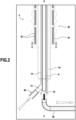
- the invention provides for connecting the conduits to one or more removable underwater heating installations such as that shown in the figure 1 .
- the heating installation 2 shown in this figure is removably connected to an underwater pipe (not shown). It is controlled from the surface installation (not shown in the figure) depending in particular on the operating mode of the network (typically: normal operating phase, preservation phase or production restart phase).
- the heating installation 2 comprises a plurality of pipe sections 4 which are connected to each other and which are arranged in a substantially vertical direction.
- the pipe sections 4 are arranged inside a parallelepipedal-shaped frame 6.
- Each pipe section 4 is arranged vertically, that is to say it extends in a mainly vertical direction, that is to say parallel to the direction of gravity.
- each pipe section 4 comprises an internal tube 8 centered on a vertical axis X-X and an external tube 10 arranged around the internal tube while being coaxial with it.
- the outer tube 10 comprises an inlet opening 12 which allows vertical circulation of the multiphase effluent from bottom to top in the annular space 14 which is delimited between the outer tube and the inner tube.
- the inner tube 8 opens inside an upper vertical end of the outer tube 10. Finally, at its lower vertical end, the inner tube 8 opens towards an outlet 16 for discharging the multiphase effluent.
- the multiphase effluent from the underwater pipe enters the pipe section 4 of the heating installation according to the invention from below by entering the annular space 14 delimited between the outer tube and the inner tube by the inlet opening 12.
- the effluent flows vertically in this annular space 14 from bottom to top, then, at the upper end of the pipe section, turns around to be directed towards the internal tube 8 inside which it flows vertically from top to bottom.
- the effluent is then discharged from the bottom of the pipe section via the discharge outlet 16.
- the passage section of the annular space 14 delimited between the external tube and the internal tube can be equal to the passage section of the internal tube 8 so that the flow rates of the effluent are identical in the upward and downward directions.
- the passage section of the annular space 14 is minimized in order to obtain the highest possible flow rate, which promotes heat transfer.
- the pressure difference between the inside of the inner tube 8 and the inside of the annular space 14 delimited between the outer tube and the inner tube is very small, so that it is possible and advantageous to give a very small thickness (of the order of a few millimeters) to the inner tube.
- the latter could be made of a corrosion-resistant alloy.
- Each pipe section 4 of the heating installation according to the invention further comprises a thermal insulation layer 18 which is arranged around the outer tube 10, as well as an induction heating system 20 of the outer tube which is arranged around the thermal insulation layer 18.
- the induction heating system 20 consists of one or more induction coils 22 which are wound in superimposed rows around the thermal insulation layer 18. These induction coils 22 are supplied with alternating electric current so as to generate an induced current in the outer tube 10 to heat it.
- the induction heating system also includes a flexible jacket 24 which is disposed around the induction coils 22 to form an enclosure. hermetic, the latter being filled with a liquid which is at equal pressure with the external environment (namely the surrounding seawater).
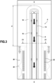
- the induction coils 22 of the heating system extend over the entire height of the pipe section, with the exception of an upper end portion P which is not surrounded by the induction coils, and therefore which is not subjected to induction heating.
- This unheated upper end portion P which is visible in particular on the figure 3 includes in particular the upper end zone of the external tube 10 into which the internal tube 8 opens (zone in which the multiphase effluent turns around to be directed inside the internal tube).
- This upper end zone of the outer tube 10 is the place in which a pocket of gas from the multiphase effluent circulating in the pipe section risks stagnating. Since this zone is not subjected to induction heating, there is therefore no risk of heating stagnant gas in this upper part which could lead to destructive overheating of the thermal insulation layer 18.
- the end portion of the outer tube 10 of the pipe section has at its upper end a shape 10a which is curved outwards.
- This curved shape 10a makes it possible to increase the resistance to the internal/external pressure differential and to limit the pressure losses of the flow of the multiphase effluent during its passage from the annular space 14 towards the inside of the inner tube 8.
- the end portion of the external tube 10 of the pipe section can enclose a conical part which is curved inwards so as to improve the guiding of the effluent from the annular space 14 towards the inside of the internal tube 8.
- the pipe section also comprises a plurality of centering devices which are positioned in the annular space 14 between the outer tube and the inner tube. These centering devices make it possible to ensure centering and maintenance of the inner tube inside the outer tube.
- the centralizers can be in the form of rings which are perforated to disturb as little as possible the flow of the multiphase effluent in the annular space between the outer tube and the inner tube.
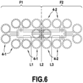
- the pipe sections 4 of the heating installation are arranged in two separate bundles F1, F2 of nine pipe sections each.
- Each bundle F1, F2 thus comprises nine pipe sections, respectively 4-1 and 4-2, the pipe sections 4-1 of one of the bundles (here the bundle F1) being supplied with multiphase effluent via a common distributor 26.
- This distributor 26 is positioned at the centre of the pipe sections 4-1 and is connected by connectors 28 (see figure 2 ) at the inlet opening 12 of the outer tube of each pipe section.
- each of the 4-1 pipe sections of the F1 bundle supplies multiphase effluent to the 4-2 pipe sections of the other F2 bundle.
- This supply of the pipe sections of the second bundle can be done in series or in cascade (i.e. in parallel).
- this supply is in series and carried out by means of connectors 30 connecting the evacuation outlet 16 of the internal tube of each pipe section 4-1 of the bundle F1 to the inlet opening 12 of the external tube of each pipe section 4-2 of the other bundle F2.
- figure 6 represents the electrical supply diagram of the heating installation according to the arrangement described in connection with the figure 5 .
- this figure 6 shows the different electrical connections of the induction coils of the heating system of each pipe section 4-1, 4-2 of the two bundles F1, F2 to the three phases of a three-phase electrical power network.
- the power supply is via a three-phase electric current, each phase L1, L2 and L3 of which is connected to a group of six pipe sections 4-1, 4-2.
- phase L1 is connected to a group of six pipe sections 4-1 of the bundle F1
- phase L2 is connected to a group of comprising three pipe sections 4-1 of the bundle F1 and three pipe sections 4-2 of the bundle F2
- L3 is connected to a group of six pipe sections 4-2 of the bundle F2.
- the driving sections of the two bundles may be arranged in a nested arrangement, rather than in two separate groups.
- the heating installation may alternately comprise three bundles of pipe sections each comprising six pipe sections.
Landscapes
- Engineering & Computer Science (AREA)
- Physics & Mathematics (AREA)
- Electromagnetism (AREA)
- General Engineering & Computer Science (AREA)
- Life Sciences & Earth Sciences (AREA)
- Geology (AREA)
- Mining & Mineral Resources (AREA)
- Mechanical Engineering (AREA)
- Geochemistry & Mineralogy (AREA)
- General Life Sciences & Earth Sciences (AREA)
- Fluid Mechanics (AREA)
- Environmental & Geological Engineering (AREA)
- Physical Or Chemical Processes And Apparatus (AREA)
- Rigid Pipes And Flexible Pipes (AREA)
- Pipe Accessories (AREA)
- Pipeline Systems (AREA)
- Lining Or Joining Of Plastics Or The Like (AREA)
Claims (15)
- Unterwassererwärmungsanlage (2) für einen mehrphasigen Abfluss, der innerhalb eines Unterwassergehäuses zirkuliert, umfassend mindestens eine Leitungssektion (4), die in einer im Wesentlichen vertikalen Richtung angeordnet ist, wobei die Leitungssektion ein Innenrohr (8), ein Außenrohr (10), das koaxial um das Innenrohr angeordnet ist, eine Wärmeisolationsschicht (18), die um das Außenrohr angeordnet ist, und ein Induktionserwärmungssystem (20) des Außenrohres, das um die Wärmeisolationsschicht angeordnet ist, umfasst, wobei das Außenrohr an einem unteren Ende eine Einlassöffnung (12) umfasst, um eine Zirkulation des mehrphasigen Abflusses von unten nach oben in einem Ringraum (14) zu ermöglichen, der zwischen dem Außenrohr und dem Innenrohr begrenzt ist, und sich das Innenrohr an einem oberen Ende in das Innere des Außenrohres öffnet und an einem unteren Ende zu einem Evakuierungsauslass (16) des mehrphasigen Abflusses mündet, um eine Gegenstromzirkulation des mehrphasigen Abflusses von oben nach unten innerhalb des Innenrohres zu ermöglichen.
- Anlage nach Anspruch 1, wobei sich das Innenrohr (8) der Leitungssektion (4) an einem oberen Ende innerhalb des Außenrohres auf Höhe eines Endabschnittes davon, der keine Induktionserwärmung aufweist, öffnet.
- Anlage nach Anspruch 2, wobei der Endabschnitt des Außenrohres (10) der Leitungssektion (4) an seinem oberen Ende eine nach außen gewölbte Form (10a) aufweist, um die Druckverluste des Flusses des mehrphasigen Abflusses auf seinem Weg von dem Ringraum zu dem Innenrohr zu begrenzen.
- Anlage nach einem der Ansprüche 2 und 3, wobei der Endabschnitt des Außenrohres der Leitungssektion einen konischen Teil umschließt, der nach innen gewölbt ist, um die Führung des Abflusses von dem Ringraum zu dem Innenrohr zu verbessern.
- Anlage nach einem der Ansprüche 1 bis 4, wobei die Durchlasssektion des Ringraums (14) im Wesentlichen gleich der Durchlasssektion des Innenrohres (8) ist.
- Anlage nach einem der Ansprüche 1 bis 5, wobei die Leitungssektion mehrere Zentriervorrichtungen umfasst, die in dem Ringraum zwischen dem Außenrohr und dem Innenrohr positioniert sind.
- Anlage nach einem der Ansprüche 1 bis 6, wobei das Induktionserwärmungssystem (20) der Leitungssektion mindestens eine Induktionsspule (22) umfasst, die um die Wärmeisolationsschicht (18) gewickelt ist und mit Wechselstrom gespeist wird, um einen induzierten Strom in dem Außenrohr zu erzeugen, um es zu erwärmen.
- Anlage nach Anspruch 7, wobei die Leitungssektion (4) ferner ein flexibles Gehäuse (24) umfasst, das um die Induktionsspule (22) des Erwärmungssystems angeordnet ist, um eine hermetische Hülle zu bilden, wobei die Hülle mit einer Flüssigkeit mit gleichem Druck wie die Außenumgebung gefüllt ist.
- Anlage nach einem der Ansprüche 1 bis 8, wobei das Innenrohr (8) der Leitungssektion (4) aus einer korrosionsbeständigen Legierung umgesetzt ist.
- Anlage nach einem der Ansprüche 1 bis 9, umfassend mehrere Leitungssektionen (4-1, 4-2), die über einen gemeinsamen Verteiler (26), in den die Einlassöffnung (12) des Außenrohres (8) jeder Leitungssektion mündet, mit mehrphasigem Abfluss gespeist werden.
- Anlage nach Anspruch 10, umfassend mindestens zwei Bündel (F1, F2) von Leitungssektionen, wobei jedes Bündel mehrere Leitungssektionen (4-1, 4-2) umfasst, wobei die Leitungssektionen des einen der Bündel über einen gemeinsamen Verteiler (26) mit mehrphasigem Abfluss gespeist werden und die Leitungssektionen eines anderen Bündels, dessen Evakuierungsauslässe zu einem gemeinsamen Sammler (32) münden, in Reihe oder in Kaskade mit mehrphasigem Abfluss speisen.
- Anlage nach Anspruch 11, umfassend zwei Bündel (F1, F2) von Leitungssektionen, die jeweils neun Leitungssektionen (4-1, 4-2) umfassen.
- Anlage nach Anspruch 11, umfassend drei Bündel von Leitungssektionen, die jeweils sechs Leitungssektionen umfassen.
- Anlage nach einem der Ansprüche 12 und 13, wobei die Leitungssektionen von allen Bündeln innerhalb eines gleichen quaderförmigen Volumens (6) in mehreren unterschiedlichen Gruppen von Leitungssektionen, die den verschiedenen Bündeln entsprechen, oder in einer verschachtelten Anordnung der Leitungssektionen der verschiedenen Bündel angeordnet sind.
- Unterwassererwärmungsverfahren eines mehrphasigen Abflusses, der innerhalb eines Unterwassergehäuses zirkuliert, umfassend das Zirkulieren des mehrphasigen Abflusses innerhalb eines Ringraums (14), der zwischen einem koaxialen Außenrohr (10) und einem koaxialen Innenrohr (8) einer vertikalen Leitungssektion (4) begrenzt ist, in einer vertikalen Richtung von unten nach oben, gefolgt von einer Gegenstromzirkulation in einer vertikalen Richtung des mehrphasigen Abflusses von oben nach unten innerhalb des Innenrohres der Leitungssektion mit Anwendung einer Induktionserwärmung des Außenrohres der Leitungssektion.
Applications Claiming Priority (2)
| Application Number | Priority Date | Filing Date | Title |
|---|---|---|---|
| FR2013626A FR3118117B1 (fr) | 2020-12-18 | 2020-12-18 | Installation et procédé sous-marin de chauffage d’un effluent polyphasique circulant à l’intérieur d’une enveloppe sous-marine |
| PCT/FR2021/051885 WO2022129709A1 (fr) | 2020-12-18 | 2021-10-27 | Installation et procédé sous-marin de chauffage d'un effluent polyphasique circulant à l'intérieur d'une enveloppe sous-marine |
Publications (2)
| Publication Number | Publication Date |
|---|---|
| EP4205508A1 EP4205508A1 (de) | 2023-07-05 |
| EP4205508B1 true EP4205508B1 (de) | 2024-10-09 |
Family
ID=74554120
Family Applications (1)
| Application Number | Title | Priority Date | Filing Date |
|---|---|---|---|
| EP21816124.8A Active EP4205508B1 (de) | 2020-12-18 | 2021-10-27 | Unterwasseranlage und verfahren zum erwärmen eines in einem unterwassergehäuse strömenden mehrphasen-abflusses |
Country Status (5)
| Country | Link |
|---|---|
| US (1) | US20240023209A1 (de) |
| EP (1) | EP4205508B1 (de) |
| BR (1) | BR112023010613A2 (de) |
| FR (1) | FR3118117B1 (de) |
| WO (1) | WO2022129709A1 (de) |
Family Cites Families (3)
| Publication number | Priority date | Publication date | Assignee | Title |
|---|---|---|---|---|
| US7950458B2 (en) * | 2007-03-26 | 2011-05-31 | J. I. Livingstone Enterprises Ltd. | Drilling, completing and stimulating a hydrocarbon production well |
| FR3028131B1 (fr) | 2014-10-31 | 2020-11-13 | Saipem Sa | Station de chauffage de fluides circulant dans un reseau de conduites sous-marines |
| CN108468897A (zh) * | 2018-05-31 | 2018-08-31 | 辽宁华燃燃气设备有限公司 | 一种高效天然气定向流动加热系统 |
-
2020
- 2020-12-18 FR FR2013626A patent/FR3118117B1/fr active Active
-
2021
- 2021-10-27 BR BR112023010613A patent/BR112023010613A2/pt unknown
- 2021-10-27 EP EP21816124.8A patent/EP4205508B1/de active Active
- 2021-10-27 WO PCT/FR2021/051885 patent/WO2022129709A1/fr not_active Ceased
- 2021-10-27 US US18/257,448 patent/US20240023209A1/en active Pending
Also Published As
| Publication number | Publication date |
|---|---|
| EP4205508A1 (de) | 2023-07-05 |
| FR3118117B1 (fr) | 2022-12-16 |
| WO2022129709A1 (fr) | 2022-06-23 |
| FR3118117A1 (fr) | 2022-06-24 |
| BR112023010613A2 (pt) | 2024-02-06 |
| US20240023209A1 (en) | 2024-01-18 |
Similar Documents
| Publication | Publication Date | Title |
|---|---|---|
| EP2198123B1 (de) | Horizontale flüssigkeits-/gastrennungsvorrichtung, flüssigkeits-/gastrennungsverfahren, insbesondere für rohöl-flüssig- und gasphasen und aufstellung der vorrichtung auf den seeboden | |
| EP3535518B1 (de) | Verfahren und vorrichtung zur induktionserwärmung eines innenrohrs einer anordnung von koaxialrohren | |
| EP3455536A1 (de) | Erwärmungsvorrichtung zum transport einer mehrphasigen mischung von kohlenwasserstoffen und zugehöriges verfahren | |
| EP3824214B1 (de) | Verfahren und system zur direkten elektrischen beheizung eines doppelwandigen rohres zum transport von flüssigkeiten | |
| FR2967752A1 (fr) | Conduit isole et chauffe realise par des troncons double enveloppe et procede de pose du conduit | |
| EP3099393B1 (de) | Modulare anlage und verfahren zur flüssigkeit/gas-trennung, insbesondere für flüssige und gasförmige phasen von rohöl | |
| EP2139576B1 (de) | Flüssigkeits-/gastrennungsvorrichtung und flüssigkeits-/gastrennungsverfahren, insbesondere für rohöl-flüssig- und gasphasen | |
| EP3835641B1 (de) | Unterwasseranlage zum beheizen eines in einem unterwassergehäuse zirkulierenden zweiphasigen flüssigkeits-/gasausflusses | |
| EP2885568B1 (de) | Zwischenkopplung zum verbinden von elementen eines starren rohrs zur förderung einer flüssigkeit sowie zugehöriges rohrnetzwerk und montageverfahren | |
| EP3213601B1 (de) | Station zum erwärmen von durch ein netzwerk aus unterwasserrohrleitungen fliessenden flüssigkeiten | |
| EP4205508B1 (de) | Unterwasseranlage und verfahren zum erwärmen eines in einem unterwassergehäuse strömenden mehrphasen-abflusses | |
| EP3631155B1 (de) | Einrichtung zum erwärmen von kohlenwasserstoff-extraktionsleitungen | |
| EP4204825B1 (de) | Verfahren zur bestimmung des linearen elektrischen wechselstromwiderstandes eines stahlrohres und vorrichtung zur durchführung eines solchen verfahrens | |
| EP4508305B1 (de) | Verfahren zur einrichtung einer vorrichtung zu geologischen sequestrierung von kohlendioxid in grundwasserlagerstätte | |
| FR3014170A1 (fr) | Refroidissement d'un dispositif de generation de vapeur | |
| OA19064A (fr) | Procédé et dispositif de chauffage par induction d'une conduite interne d'un ensemble de conduites coaxiales. | |
| OA19925A (fr) | Procédé et système de chauffage électrique direct d'une conduite à double enveloppe pour le transport de fluides. | |
| OA19947A (fr) | Installation modulaire et procédé de séparation liquide/gaz, notamment des phases liquide et gazeuse d'un pétrole brut. |
Legal Events
| Date | Code | Title | Description |
|---|---|---|---|
| STAA | Information on the status of an ep patent application or granted ep patent |
Free format text: STATUS: UNKNOWN |
|
| STAA | Information on the status of an ep patent application or granted ep patent |
Free format text: STATUS: THE INTERNATIONAL PUBLICATION HAS BEEN MADE |
|
| PUAI | Public reference made under article 153(3) epc to a published international application that has entered the european phase |
Free format text: ORIGINAL CODE: 0009012 |
|
| STAA | Information on the status of an ep patent application or granted ep patent |
Free format text: STATUS: REQUEST FOR EXAMINATION WAS MADE |
|
| 17P | Request for examination filed |
Effective date: 20230328 |
|
| AK | Designated contracting states |
Kind code of ref document: A1 Designated state(s): AL AT BE BG CH CY CZ DE DK EE ES FI FR GB GR HR HU IE IS IT LI LT LU LV MC MK MT NL NO PL PT RO RS SE SI SK SM TR |
|
| DAV | Request for validation of the european patent (deleted) | ||
| DAX | Request for extension of the european patent (deleted) | ||
| GRAP | Despatch of communication of intention to grant a patent |
Free format text: ORIGINAL CODE: EPIDOSNIGR1 |
|
| STAA | Information on the status of an ep patent application or granted ep patent |
Free format text: STATUS: GRANT OF PATENT IS INTENDED |
|
| INTG | Intention to grant announced |
Effective date: 20240429 |
|
| GRAS | Grant fee paid |
Free format text: ORIGINAL CODE: EPIDOSNIGR3 |
|
| GRAA | (expected) grant |
Free format text: ORIGINAL CODE: 0009210 |
|
| STAA | Information on the status of an ep patent application or granted ep patent |
Free format text: STATUS: THE PATENT HAS BEEN GRANTED |
|
| RAP3 | Party data changed (applicant data changed or rights of an application transferred) |
Owner name: SAIPEM S.A. |
|
| AK | Designated contracting states |
Kind code of ref document: B1 Designated state(s): AL AT BE BG CH CY CZ DE DK EE ES FI FR GB GR HR HU IE IS IT LI LT LU LV MC MK MT NL NO PL PT RO RS SE SI SK SM TR |
|
| REG | Reference to a national code |
Ref country code: CH Ref legal event code: EP |
|
| REG | Reference to a national code |
Ref country code: DE Ref legal event code: R096 Ref document number: 602021020099 Country of ref document: DE |
|
| REG | Reference to a national code |
Ref country code: IE Ref legal event code: FG4D Free format text: LANGUAGE OF EP DOCUMENT: FRENCH |
|
| REG | Reference to a national code |
Ref country code: NL Ref legal event code: FP |
|
| REG | Reference to a national code |
Ref country code: LT Ref legal event code: MG9D |
|
| REG | Reference to a national code |
Ref country code: AT Ref legal event code: MK05 Ref document number: 1732061 Country of ref document: AT Kind code of ref document: T Effective date: 20241009 |
|
| PG25 | Lapsed in a contracting state [announced via postgrant information from national office to epo] |
Ref country code: HR Free format text: LAPSE BECAUSE OF FAILURE TO SUBMIT A TRANSLATION OF THE DESCRIPTION OR TO PAY THE FEE WITHIN THE PRESCRIBED TIME-LIMIT Effective date: 20241009 Ref country code: PT Free format text: LAPSE BECAUSE OF FAILURE TO SUBMIT A TRANSLATION OF THE DESCRIPTION OR TO PAY THE FEE WITHIN THE PRESCRIBED TIME-LIMIT Effective date: 20250210 Ref country code: IS Free format text: LAPSE BECAUSE OF FAILURE TO SUBMIT A TRANSLATION OF THE DESCRIPTION OR TO PAY THE FEE WITHIN THE PRESCRIBED TIME-LIMIT Effective date: 20250209 |
|
| PG25 | Lapsed in a contracting state [announced via postgrant information from national office to epo] |
Ref country code: FI Free format text: LAPSE BECAUSE OF FAILURE TO SUBMIT A TRANSLATION OF THE DESCRIPTION OR TO PAY THE FEE WITHIN THE PRESCRIBED TIME-LIMIT Effective date: 20241009 |
|
| PG25 | Lapsed in a contracting state [announced via postgrant information from national office to epo] |
Ref country code: BG Free format text: LAPSE BECAUSE OF FAILURE TO SUBMIT A TRANSLATION OF THE DESCRIPTION OR TO PAY THE FEE WITHIN THE PRESCRIBED TIME-LIMIT Effective date: 20241009 |
|
| PG25 | Lapsed in a contracting state [announced via postgrant information from national office to epo] |
Ref country code: ES Free format text: LAPSE BECAUSE OF FAILURE TO SUBMIT A TRANSLATION OF THE DESCRIPTION OR TO PAY THE FEE WITHIN THE PRESCRIBED TIME-LIMIT Effective date: 20241009 |
|
| PG25 | Lapsed in a contracting state [announced via postgrant information from national office to epo] |
Ref country code: LV Free format text: LAPSE BECAUSE OF FAILURE TO SUBMIT A TRANSLATION OF THE DESCRIPTION OR TO PAY THE FEE WITHIN THE PRESCRIBED TIME-LIMIT Effective date: 20241009 Ref country code: GR Free format text: LAPSE BECAUSE OF FAILURE TO SUBMIT A TRANSLATION OF THE DESCRIPTION OR TO PAY THE FEE WITHIN THE PRESCRIBED TIME-LIMIT Effective date: 20250110 Ref country code: AT Free format text: LAPSE BECAUSE OF FAILURE TO SUBMIT A TRANSLATION OF THE DESCRIPTION OR TO PAY THE FEE WITHIN THE PRESCRIBED TIME-LIMIT Effective date: 20241009 |
|
| PG25 | Lapsed in a contracting state [announced via postgrant information from national office to epo] |
Ref country code: PL Free format text: LAPSE BECAUSE OF FAILURE TO SUBMIT A TRANSLATION OF THE DESCRIPTION OR TO PAY THE FEE WITHIN THE PRESCRIBED TIME-LIMIT Effective date: 20241009 |
|
| PG25 | Lapsed in a contracting state [announced via postgrant information from national office to epo] |
Ref country code: RS Free format text: LAPSE BECAUSE OF FAILURE TO SUBMIT A TRANSLATION OF THE DESCRIPTION OR TO PAY THE FEE WITHIN THE PRESCRIBED TIME-LIMIT Effective date: 20250109 |
|
| REG | Reference to a national code |
Ref country code: DE Ref legal event code: R119 Ref document number: 602021020099 Country of ref document: DE |
|
| REG | Reference to a national code |
Ref country code: CH Ref legal event code: PL |
|
| PG25 | Lapsed in a contracting state [announced via postgrant information from national office to epo] |
Ref country code: SM Free format text: LAPSE BECAUSE OF FAILURE TO SUBMIT A TRANSLATION OF THE DESCRIPTION OR TO PAY THE FEE WITHIN THE PRESCRIBED TIME-LIMIT Effective date: 20241009 |
|
| PG25 | Lapsed in a contracting state [announced via postgrant information from national office to epo] |
Ref country code: MC Free format text: LAPSE BECAUSE OF FAILURE TO SUBMIT A TRANSLATION OF THE DESCRIPTION OR TO PAY THE FEE WITHIN THE PRESCRIBED TIME-LIMIT Effective date: 20241009 |
|
| PG25 | Lapsed in a contracting state [announced via postgrant information from national office to epo] |
Ref country code: DE Free format text: LAPSE BECAUSE OF NON-PAYMENT OF DUE FEES Effective date: 20250501 |
|
| PG25 | Lapsed in a contracting state [announced via postgrant information from national office to epo] |
Ref country code: DK Free format text: LAPSE BECAUSE OF FAILURE TO SUBMIT A TRANSLATION OF THE DESCRIPTION OR TO PAY THE FEE WITHIN THE PRESCRIBED TIME-LIMIT Effective date: 20241009 |
|
| PG25 | Lapsed in a contracting state [announced via postgrant information from national office to epo] |
Ref country code: LU Free format text: LAPSE BECAUSE OF NON-PAYMENT OF DUE FEES Effective date: 20241027 Ref country code: BE Free format text: LAPSE BECAUSE OF NON-PAYMENT OF DUE FEES Effective date: 20241031 |
|
| PG25 | Lapsed in a contracting state [announced via postgrant information from national office to epo] |
Ref country code: EE Free format text: LAPSE BECAUSE OF FAILURE TO SUBMIT A TRANSLATION OF THE DESCRIPTION OR TO PAY THE FEE WITHIN THE PRESCRIBED TIME-LIMIT Effective date: 20241009 |
|
| PG25 | Lapsed in a contracting state [announced via postgrant information from national office to epo] |
Ref country code: CH Free format text: LAPSE BECAUSE OF NON-PAYMENT OF DUE FEES Effective date: 20241031 |
|
| PG25 | Lapsed in a contracting state [announced via postgrant information from national office to epo] |
Ref country code: RO Free format text: LAPSE BECAUSE OF FAILURE TO SUBMIT A TRANSLATION OF THE DESCRIPTION OR TO PAY THE FEE WITHIN THE PRESCRIBED TIME-LIMIT Effective date: 20241009 |
|
| PG25 | Lapsed in a contracting state [announced via postgrant information from national office to epo] |
Ref country code: SK Free format text: LAPSE BECAUSE OF FAILURE TO SUBMIT A TRANSLATION OF THE DESCRIPTION OR TO PAY THE FEE WITHIN THE PRESCRIBED TIME-LIMIT Effective date: 20241009 |
|
| PG25 | Lapsed in a contracting state [announced via postgrant information from national office to epo] |
Ref country code: CZ Free format text: LAPSE BECAUSE OF FAILURE TO SUBMIT A TRANSLATION OF THE DESCRIPTION OR TO PAY THE FEE WITHIN THE PRESCRIBED TIME-LIMIT Effective date: 20241009 |
|
| REG | Reference to a national code |
Ref country code: BE Ref legal event code: MM Effective date: 20241031 |
|
| RAP4 | Party data changed (patent owner data changed or rights of a patent transferred) |
Owner name: SAIPEM S.A. |
|
| PLBE | No opposition filed within time limit |
Free format text: ORIGINAL CODE: 0009261 |
|
| STAA | Information on the status of an ep patent application or granted ep patent |
Free format text: STATUS: NO OPPOSITION FILED WITHIN TIME LIMIT |
|
| PG25 | Lapsed in a contracting state [announced via postgrant information from national office to epo] |
Ref country code: SE Free format text: LAPSE BECAUSE OF FAILURE TO SUBMIT A TRANSLATION OF THE DESCRIPTION OR TO PAY THE FEE WITHIN THE PRESCRIBED TIME-LIMIT Effective date: 20241009 |
|
| 26N | No opposition filed |
Effective date: 20250710 |
|
| PGFP | Annual fee paid to national office [announced via postgrant information from national office to epo] |
Ref country code: NL Payment date: 20250926 Year of fee payment: 5 |
|
| PG25 | Lapsed in a contracting state [announced via postgrant information from national office to epo] |
Ref country code: IE Free format text: LAPSE BECAUSE OF NON-PAYMENT OF DUE FEES Effective date: 20241027 |
|
| P01 | Opt-out of the competence of the unified patent court (upc) registered |
Free format text: CASE NUMBER: UPC_APP_9427_4205508/2025 Effective date: 20251009 |
|
| PGFP | Annual fee paid to national office [announced via postgrant information from national office to epo] |
Ref country code: GB Payment date: 20251023 Year of fee payment: 5 |
|
| PGFP | Annual fee paid to national office [announced via postgrant information from national office to epo] |
Ref country code: NO Payment date: 20250930 Year of fee payment: 5 |
|
| PGFP | Annual fee paid to national office [announced via postgrant information from national office to epo] |
Ref country code: IT Payment date: 20251007 Year of fee payment: 5 |
|
| PGFP | Annual fee paid to national office [announced via postgrant information from national office to epo] |
Ref country code: FR Payment date: 20251021 Year of fee payment: 5 |
|
| PG25 | Lapsed in a contracting state [announced via postgrant information from national office to epo] |
Ref country code: CY Free format text: LAPSE BECAUSE OF FAILURE TO SUBMIT A TRANSLATION OF THE DESCRIPTION OR TO PAY THE FEE WITHIN THE PRESCRIBED TIME-LIMIT; INVALID AB INITIO Effective date: 20211027 |
|
| PG25 | Lapsed in a contracting state [announced via postgrant information from national office to epo] |
Ref country code: HU Free format text: LAPSE BECAUSE OF FAILURE TO SUBMIT A TRANSLATION OF THE DESCRIPTION OR TO PAY THE FEE WITHIN THE PRESCRIBED TIME-LIMIT; INVALID AB INITIO Effective date: 20211027 |