EP3835641B1 - Unterwasseranlage zum beheizen eines in einem unterwassergehäuse zirkulierenden zweiphasigen flüssigkeits-/gasausflusses - Google Patents
Unterwasseranlage zum beheizen eines in einem unterwassergehäuse zirkulierenden zweiphasigen flüssigkeits-/gasausflusses Download PDFInfo
- Publication number
- EP3835641B1 EP3835641B1 EP20213367.4A EP20213367A EP3835641B1 EP 3835641 B1 EP3835641 B1 EP 3835641B1 EP 20213367 A EP20213367 A EP 20213367A EP 3835641 B1 EP3835641 B1 EP 3835641B1
- Authority
- EP
- European Patent Office
- Prior art keywords
- heating
- pipe sections
- installation
- heated pipe
- heated
- Prior art date
- Legal status (The legal status is an assumption and is not a legal conclusion. Google has not performed a legal analysis and makes no representation as to the accuracy of the status listed.)
- Active
Links
Images


Classifications
-
- F—MECHANICAL ENGINEERING; LIGHTING; HEATING; WEAPONS; BLASTING
- F16—ENGINEERING ELEMENTS AND UNITS; GENERAL MEASURES FOR PRODUCING AND MAINTAINING EFFECTIVE FUNCTIONING OF MACHINES OR INSTALLATIONS; THERMAL INSULATION IN GENERAL
- F16L—PIPES; JOINTS OR FITTINGS FOR PIPES; SUPPORTS FOR PIPES, CABLES OR PROTECTIVE TUBING; MEANS FOR THERMAL INSULATION IN GENERAL
- F16L53/00—Heating of pipes or pipe systems; Cooling of pipes or pipe systems
- F16L53/30—Heating of pipes or pipe systems
- F16L53/34—Heating of pipes or pipe systems using electric, magnetic or electromagnetic fields, e.g. induction, dielectric or microwave heating
-
- E—FIXED CONSTRUCTIONS
- E21—EARTH OR ROCK DRILLING; MINING
- E21B—EARTH OR ROCK DRILLING; OBTAINING OIL, GAS, WATER, SOLUBLE OR MELTABLE MATERIALS OR A SLURRY OF MINERALS FROM WELLS
- E21B43/00—Methods or apparatus for obtaining oil, gas, water, soluble or meltable materials or a slurry of minerals from wells
- E21B43/16—Enhanced recovery methods for obtaining hydrocarbons
- E21B43/24—Enhanced recovery methods for obtaining hydrocarbons using heat, e.g. steam injection
- E21B43/2401—Enhanced recovery methods for obtaining hydrocarbons using heat, e.g. steam injection by means of electricity
-
- E—FIXED CONSTRUCTIONS
- E21—EARTH OR ROCK DRILLING; MINING
- E21B—EARTH OR ROCK DRILLING; OBTAINING OIL, GAS, WATER, SOLUBLE OR MELTABLE MATERIALS OR A SLURRY OF MINERALS FROM WELLS
- E21B36/00—Heating, cooling or insulating arrangements for boreholes or wells, e.g. for use in permafrost zones
- E21B36/005—Heater surrounding production tube
-
- E—FIXED CONSTRUCTIONS
- E21—EARTH OR ROCK DRILLING; MINING
- E21B—EARTH OR ROCK DRILLING; OBTAINING OIL, GAS, WATER, SOLUBLE OR MELTABLE MATERIALS OR A SLURRY OF MINERALS FROM WELLS
- E21B43/00—Methods or apparatus for obtaining oil, gas, water, soluble or meltable materials or a slurry of minerals from wells
- E21B43/01—Methods or apparatus for obtaining oil, gas, water, soluble or meltable materials or a slurry of minerals from wells specially adapted for obtaining from underwater installations
-
- H—ELECTRICITY
- H05—ELECTRIC TECHNIQUES NOT OTHERWISE PROVIDED FOR
- H05B—ELECTRIC HEATING; ELECTRIC LIGHT SOURCES NOT OTHERWISE PROVIDED FOR; CIRCUIT ARRANGEMENTS FOR ELECTRIC LIGHT SOURCES, IN GENERAL
- H05B6/00—Heating by electric, magnetic or electromagnetic fields
- H05B6/02—Induction heating
- H05B6/10—Induction heating apparatus, other than furnaces, for specific applications
- H05B6/105—Induction heating apparatus, other than furnaces, for specific applications using a susceptor
- H05B6/108—Induction heating apparatus, other than furnaces, for specific applications using a susceptor for heating a fluid
-
- H—ELECTRICITY
- H05—ELECTRIC TECHNIQUES NOT OTHERWISE PROVIDED FOR
- H05B—ELECTRIC HEATING; ELECTRIC LIGHT SOURCES NOT OTHERWISE PROVIDED FOR; CIRCUIT ARRANGEMENTS FOR ELECTRIC LIGHT SOURCES, IN GENERAL
- H05B6/00—Heating by electric, magnetic or electromagnetic fields
- H05B6/02—Induction heating
- H05B6/36—Coil arrangements
- H05B6/44—Coil arrangements having more than one coil or coil segment
-
- F—MECHANICAL ENGINEERING; LIGHTING; HEATING; WEAPONS; BLASTING
- F17—STORING OR DISTRIBUTING GASES OR LIQUIDS
- F17D—PIPE-LINE SYSTEMS; PIPE-LINES
- F17D1/00—Pipe-line systems
- F17D1/005—Pipe-line systems for a two-phase gas-liquid flow
-
- H—ELECTRICITY
- H05—ELECTRIC TECHNIQUES NOT OTHERWISE PROVIDED FOR
- H05B—ELECTRIC HEATING; ELECTRIC LIGHT SOURCES NOT OTHERWISE PROVIDED FOR; CIRCUIT ARRANGEMENTS FOR ELECTRIC LIGHT SOURCES, IN GENERAL
- H05B2206/00—Aspects relating to heating by electric, magnetic, or electromagnetic fields covered by group H05B6/00
- H05B2206/02—Induction heating
- H05B2206/022—Special supports for the induction coils
-
- H—ELECTRICITY
- H05—ELECTRIC TECHNIQUES NOT OTHERWISE PROVIDED FOR
- H05B—ELECTRIC HEATING; ELECTRIC LIGHT SOURCES NOT OTHERWISE PROVIDED FOR; CIRCUIT ARRANGEMENTS FOR ELECTRIC LIGHT SOURCES, IN GENERAL
- H05B2214/00—Aspects relating to resistive heating, induction heating and heating using microwaves, covered by groups H05B3/00, H05B6/00
- H05B2214/03—Heating of hydrocarbons
Definitions
- the present invention relates to the general field of heating metal fluid transport pipes, and in particular underwater pipes lying on the seabed and providing a connection between underwater hydrocarbon production wells, in particular oil and gas, and a surface installation, for example a floating production, storage and unloading unit.
- two-phase effluents from underwater hydrocarbon production wells come out at a relatively high temperature at seabed level (typically around 70°C). Since seawater is generally cold, especially at great depths where it is typically 4°C, if no measures are taken to conserve the heat of the effluents leaving the production wells, they will gradually cool down as they travel through the kilometers of underwater pipes.
- these two-phase effluents contain various chemical compounds for which cooling causes phenomena that are troublesome for maintaining good circulation conditions.
- gas molecules particularly methane
- water molecules combine with water molecules to form hydrate crystals at low temperatures.
- These crystals can stick to the walls, clump together, and lead to the formation of plugs capable of blocking the underwater pipeline.
- solubility of high-molecular-weight compounds, such as paraffins or asphaltenes, in oil decreases as the temperature drops, resulting in solid deposits that can also block the underwater pipeline.
- a known solution to prevent blockages in subsea pipelines is to heat the subsea pipelines along their entire length using one or more electrical cables wrapped around the pipelines to heat them by the Joule effect.
- This solution called “trace heating,” allows two-phase effluents transported in subsea pipelines to be maintained at a temperature above a critical threshold throughout their entire path from the production well to the surface facility.
- each heating station can comprise a number of horizontal conduit windings which is a multiple of the number of phases of the supply electric current, the conduit windings each being a section of conduit around which a solenoid is wound, the solenoids being electrically mounted so as to obtain a mounting polyphase.
- This type of architecture thus offers great ease of installation and great flexibility of use.
- the design of the local heating station must allow for the injection of very high levels of thermal power while minimizing the length of pipe to be heated and respecting a maximum pipe temperature (typically of the order of 150°C).
- a maximum pipe temperature typically of the order of 150°C.
- the heating station solution presented in the publication WO 2016/066968 requires heating very long lengths of pipe, which significantly increases the weight and dimensions of the heating station.
- the main object of the present invention is therefore to propose a heating installation which does not have the aforementioned drawbacks.
- this aim is achieved by means of an underwater installation for heating a two-phase liquid/gas effluent circulating inside an underwater envelope according to the characteristics of independent claim 1.
- the heating installation according to the invention is remarkable in that the heated pipe sections are inclined relative to the horizontal.
- horizontal is meant here any direction perpendicular to the direction of gravity. This inclination makes it possible to promote a distributed flow regime of the two-phase effluent circulating in the installation.
- a so-called “distributed” flow (and in particular a slug flow) is characterized by a structure having a succession of gas pockets and liquid slugs which contain small bubbles. This type of flow is opposed to a so-called “stratified” flow which is obtained by a two-phase effluent flow circulating in horizontal pipe sections and whose liquid/gas interface is in the form of a continuous surface separating the two phases (the liquid is located below the gas under the effect of gravity).
- a distributed flow regime makes it possible to increase the heat exchange coefficient between the pipe section and the two-phase effluent (in particular compared to a stratified flow which is inhomogeneous and detrimental to the heat exchange coefficient).
- the inclination of the heated pipe sections thus makes it possible to obtain a distributed flow regime and significantly improve the heat exchange coefficient and therefore promote the transfer of very high thermal powers. In this way, for the same levels of injected power, it is possible to very significantly reduce the length of the heated pipe sections, and therefore reduce the size and weight of the heating installation.
- At least one of the curved pipe sections is provided with an induction heating system (even if the flow in these curved pipe sections may be less distributed than for the heated pipe sections).
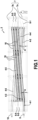
- the circuit is repeated according to this same pattern so as to form a heating coil comprising here six heated pipe sections 4-1 to 4-6 which are connected to each other by five curved pipe sections 6-1 to 6-5, an inlet 8 and an outlet 10, the inlet and outlet being offset vertically and horizontally from each other.
- the heated pipe sections 4-1 to 4-6 are straight. Of course, they could be curved.
- the heated pipe sections 4-1 to 4-6 are each inclined relative to the horizontal (or relative to the horizontal tubes 7b of the frame 7) by the same angle ⁇ which is between 2 and 10°, and which is preferably equal to 5°.
- the heated pipe sections 4-1 to 4-6 are each ascending in the direction of effluent flow, and the curved pipe sections 6-1 to 6-5 are each descending in the direction of effluent flow.
- heated pipe sections 4-1, 4-3 and 4-5 are parallel to each other, as are heated pipe sections 4-2, 4-4 and 4-6.
- the inclination of the heated pipe sections makes it possible to promote a so-called “distributed” flow regime, and more particularly a plug flow, of the two-phase effluent circulating in the installation.
- a distributed flow has a structure that presents a succession of gas pockets and liquid plugs containing small bubbles. This type of flow is opposed to a so-called “stratified” flow which is obtained by a two-phase effluent flow circulating in horizontal pipe sections and whose liquid/gas interface is in the form of a continuous surface separating the two phases (the liquid is located below the gas under the effect of gravity).
- At least the heated pipe sections 4-1 to 4-6 are each provided with an induction heating system.
- the heating system for each heated pipe section includes at least one induction coil 16 (or solenoid) that is disposed around the heated pipe section 4-1 to 4-6 over at least a portion of its length.
- induction coils 16 are supplied from the surface installation with three-phase electric current. Since the heated pipe sections are made of steel, the power supply to the induction coils generates an induced current in them, which causes them to heat up. The heat is then transmitted by the heated pipe sections to the circulating two-phase fluid by convection.
- the induction coils of the heating system have an electrical power of between 1 and 100 kW per meter of coiled pipe.
- the heated pipe sections 4-1 to 4-6, as well as the curved pipe sections 6-1 to 6-5, may be covered with a layer of thermal insulation 18.
- the induction coils 16 are wound around this layer of thermal insulation.
- This embodiment differs from that previously described in particular by its heating coil architecture which comprises twelve sections of straight heated pipes 4'-1 to 4'-12 which are successively connected to each other by eleven curved pipe sections 6'-1 to 6'-11.
- the heated pipe sections 4'-1 to 4'-12 are each equipped with an induction heating system (on the Figure 3 , for convenience, only the 4'-9 pipe section is shown with an induction coil 16).
- the inlet 8' and the outlet 10' are aligned vertically and offset horizontally from each other.
Landscapes
- Engineering & Computer Science (AREA)
- Physics & Mathematics (AREA)
- Geology (AREA)
- Life Sciences & Earth Sciences (AREA)
- Mining & Mineral Resources (AREA)
- Electromagnetism (AREA)
- Environmental & Geological Engineering (AREA)
- Fluid Mechanics (AREA)
- General Life Sciences & Earth Sciences (AREA)
- Geochemistry & Mineralogy (AREA)
- General Engineering & Computer Science (AREA)
- Mechanical Engineering (AREA)
- General Induction Heating (AREA)
Claims (10)
- Unterwasserheizanlage (2; 2') für einen zweiphasigen Flüssigkeits-/Gasabfluss, der innerhalb einer Unterwasserhülle zirkuliert, umfassend eine Vielzahl von beheizten Leitungsabschnitten (4-1 bis 4-6; 4'-1 bis 4'-12), die nacheinander durch gebogene Leitungsabschnitte (6-1 bis 6-5; 6'-1 bis 6'-11) miteinander verbunden sind, um eine Heizschlange zu bilden, wobei jeder beheizte Leitungsabschnitt in Bezug auf die Horizontale um einen Winkel (α) zwischen 2 und 10° geneigt ist, um ein verteiltes Strömungsregime des zweiphasigen Abflusses zu begünstigen, und mit einem Induktionsheizsystem (16) versehen ist, die Heizanlage auch umfassend einen Rahmen (7), wobei die Heizschlange an dem Rahmen (7) montiert ist, der durch eine Anordnung von vertikalen (7a) und horizontalen (7b) Rohren gebildet ist, wobei jeder beheizte Leitungsabschnitt in Bezug auf die horizontalen Rohre (7b) des Rahmens (7) um den Winkel (α) zwischen 2 und 10° geneigt ist.
- Anlage nach Anspruch 1, wobei die Heizschlange einen Einlass (8; 8') umfasst, der dazu bestimmt ist, mit der Unterwasserhülle verbunden zu werden und der in einen beheizten Leitungsabschnitt mündet, der für den darin zirkulierenden Abfluss ansteigend ist.
- Anlage nach einem der Ansprüche 1 oder 2, wobei die beheizten Leitungsabschnitte im Wesentlichen geradlinig sind.
- Anlage nach einem der Ansprüche 1 bis 3, wobei die beheizten Leitungsabschnitte der Heizschlange für den Abfluss jeweils aufsteigend und die gebogenen Leitungsabschnitte für den Abfluss jeweils absteigend sind.
- Anlage (2) nach einem der Ansprüche 1 bis 4, wobei die Heizschlange mindestens sechs geradlinige Leitungsabschnitte (4-1 bis 4-6), die durch mindestens fünf gebogene Leitungsabschnitte (6-1 bis 6-5) miteinander verbunden sind, einen Einlass (8), der dazu bestimmt ist, mit der Unterwasserhülle verbunden zu werden, und einen Auslass (10) umfasst, wobei der Einlass und der Auslass vorzugsweise vertikal zueinander versetzt sind.
- Anlage nach einem der Ansprüche 1 bis 5, wobei jeder beheizte Leitungsabschnitt der Heizschlange in Bezug auf die Horizontale um einen Winkel (α) von 5° geneigt ist.
- Anlage nach einem der Ansprüche 1 bis 6, wobei mindestens einer der gebogenen Leitungsabschnitte mit einem Induktionsheizsystem versehen ist.
- Anlage nach einem der Ansprüche 1 bis 7, wobei das Heizsystem von jedem beheizten Leitungsabschnitt der Heizschlange mindestens eine Induktionsspule (16) umfasst, die um den beheizten Leitungsabschnitt über mindestens einen Teil seiner Länge angeordnet ist und mit einem elektrischen Strom versorgt wird, um einen induzierten Strom in dem beheizten Leitungsabschnitt zu erzeugen, der geeignet ist, um dessen Erwärmung zu bewirken.
- Anlage nach Anspruch 8, wobei die Induktionsspulen des Heizsystems eine elektrische Leistung zwischen 1 und 100 kW pro Meter gewickelter Leitung besitzen.
- Anlage nach einem der Ansprüche 8 oder 9, wobei die beheizten Leitungsabschnitte mit einer Wärmeisolierungsschicht (18) bedeckt sind, um die die Induktionsspulen (16) gewickelt sind.
Applications Claiming Priority (1)
| Application Number | Priority Date | Filing Date | Title |
|---|---|---|---|
| FR1914434A FR3104669B1 (fr) | 2019-12-13 | 2019-12-13 | Installation sous-marine de chauffage d’un effluent diphasique liquide/gaz circulant à l’intérieur d’une enveloppe sous-marine |
Publications (2)
| Publication Number | Publication Date |
|---|---|
| EP3835641A1 EP3835641A1 (de) | 2021-06-16 |
| EP3835641B1 true EP3835641B1 (de) | 2025-03-26 |
Family
ID=69811234
Family Applications (1)
| Application Number | Title | Priority Date | Filing Date |
|---|---|---|---|
| EP20213367.4A Active EP3835641B1 (de) | 2019-12-13 | 2020-12-11 | Unterwasseranlage zum beheizen eines in einem unterwassergehäuse zirkulierenden zweiphasigen flüssigkeits-/gasausflusses |
Country Status (4)
| Country | Link |
|---|---|
| US (1) | US12091951B2 (de) |
| EP (1) | EP3835641B1 (de) |
| BR (1) | BR102020022903A8 (de) |
| FR (1) | FR3104669B1 (de) |
Families Citing this family (2)
| Publication number | Priority date | Publication date | Assignee | Title |
|---|---|---|---|---|
| US20210231249A1 (en) * | 2020-01-28 | 2021-07-29 | Chevron U.S.A. Inc. | Systems and methods for thermal management of subsea conduits using an interconnecting conduit and valving arrangement |
| US11634970B2 (en) | 2020-01-28 | 2023-04-25 | Chevron U.S.A. Inc. | Systems and methods for thermal management of subsea conduits using a jumper having adjustable insulating elements |
Family Cites Families (10)
| Publication number | Priority date | Publication date | Assignee | Title |
|---|---|---|---|---|
| US5203682A (en) * | 1991-09-04 | 1993-04-20 | Baker Hughes Incorporated | Inclined pressure boost pump |
| JP4108376B2 (ja) * | 2002-06-14 | 2008-06-25 | 臼井国際産業株式会社 | ディーゼルエンジン用リターン燃料冷却器 |
| FR2899288B1 (fr) * | 2006-03-30 | 2008-06-13 | Total Sa | Procede et dispositif pour la compression d'un fluide multiphasique |
| FR2915298B1 (fr) * | 2007-04-23 | 2009-07-03 | Inst Francais Du Petrole | Methode pour dimensionner des installations industrielles ou un melange diphasique gaz-liquide s'ecoule en regime intermittent |
| JP2011122804A (ja) * | 2009-12-14 | 2011-06-23 | Fuji Denki Thermosystems Kk | 水蒸気発生装置 |
| FR3028131B1 (fr) | 2014-10-31 | 2020-11-13 | Saipem Sa | Station de chauffage de fluides circulant dans un reseau de conduites sous-marines |
| EP3040507A1 (de) * | 2014-12-29 | 2016-07-06 | Shell Internationale Research Maatschappij B.V. | Verfahren und System zur Verfolgung von Slugs in Ölfeldrohren |
| US10830016B2 (en) * | 2016-10-19 | 2020-11-10 | Onesubsea Ip Uk Limited | Regulating the temperature of a subsea process flow |
| RU2658658C1 (ru) * | 2017-08-24 | 2018-06-22 | Общество с ограниченной ответственностью "В-Плазма" | Электрический парогенератор |
| CN209131448U (zh) * | 2018-10-31 | 2019-07-19 | 天津渤大硫酸工业有限公司 | 一种用于硫酸的斜面式蛇形换热器 |
-
2019
- 2019-12-13 FR FR1914434A patent/FR3104669B1/fr active Active
-
2020
- 2020-11-10 BR BR102020022903A patent/BR102020022903A8/pt active Search and Examination
- 2020-12-02 US US17/109,777 patent/US12091951B2/en active Active
- 2020-12-11 EP EP20213367.4A patent/EP3835641B1/de active Active
Also Published As
| Publication number | Publication date |
|---|---|
| EP3835641A1 (de) | 2021-06-16 |
| FR3104669B1 (fr) | 2021-11-26 |
| BR102020022903A2 (pt) | 2021-06-29 |
| US20210180436A1 (en) | 2021-06-17 |
| US12091951B2 (en) | 2024-09-17 |
| FR3104669A1 (fr) | 2021-06-18 |
| BR102020022903A8 (pt) | 2024-01-02 |
Similar Documents
| Publication | Publication Date | Title |
|---|---|---|
| EP3535518B1 (de) | Verfahren und vorrichtung zur induktionserwärmung eines innenrohrs einer anordnung von koaxialrohren | |
| EP2198123B1 (de) | Horizontale flüssigkeits-/gastrennungsvorrichtung, flüssigkeits-/gastrennungsverfahren, insbesondere für rohöl-flüssig- und gasphasen und aufstellung der vorrichtung auf den seeboden | |
| EP0836751B1 (de) | Thermoelektrischer generator | |
| FR2975748A1 (fr) | Dispositif sous-marin de transport d'hydrocarbures et de regulation de leur temperature | |
| EP3835641B1 (de) | Unterwasseranlage zum beheizen eines in einem unterwassergehäuse zirkulierenden zweiphasigen flüssigkeits-/gasausflusses | |
| EP3824214B1 (de) | Verfahren und system zur direkten elektrischen beheizung eines doppelwandigen rohres zum transport von flüssigkeiten | |
| FR2967752A1 (fr) | Conduit isole et chauffe realise par des troncons double enveloppe et procede de pose du conduit | |
| EP3212881B1 (de) | Verfahren zur verwaltung der beheizung von flüssigkeitsströmen durch ein netzwerk aus unterwasserrohrleitungen | |
| FR2915403A1 (fr) | Dispositif de separation liquide/gaz et procede de separation liquide/gaz, notamment les phases liquide et gazeuse d'un petrole brut | |
| EP3213601B1 (de) | Station zum erwärmen von durch ein netzwerk aus unterwasserrohrleitungen fliessenden flüssigkeiten | |
| EP4205508B1 (de) | Unterwasseranlage und verfahren zum erwärmen eines in einem unterwassergehäuse strömenden mehrphasen-abflusses | |
| EP3631155A1 (de) | Einrichtung zum erwärmen von kohlenwasserstoff-extraktionsleitungen | |
| WO2019234343A1 (fr) | Installation sous-marine et procédé de refroidissement d'un fluide dans un échangeur de chaleur par circulation d'eau de mer | |
| EP4204825B1 (de) | Verfahren zur bestimmung des linearen elektrischen wechselstromwiderstandes eines stahlrohres und vorrichtung zur durchführung eines solchen verfahrens | |
| FR3014170A1 (fr) | Refroidissement d'un dispositif de generation de vapeur | |
| OA19064A (fr) | Procédé et dispositif de chauffage par induction d'une conduite interne d'un ensemble de conduites coaxiales. | |
| OA19925A (fr) | Procédé et système de chauffage électrique direct d'une conduite à double enveloppe pour le transport de fluides. | |
| FR2931188A1 (fr) | Dispositif de rechauffage pour conduites petrolieres sous marines par grands fonds et a usage multiple |
Legal Events
| Date | Code | Title | Description |
|---|---|---|---|
| PUAI | Public reference made under article 153(3) epc to a published international application that has entered the european phase |
Free format text: ORIGINAL CODE: 0009012 |
|
| STAA | Information on the status of an ep patent application or granted ep patent |
Free format text: STATUS: THE APPLICATION HAS BEEN PUBLISHED |
|
| AK | Designated contracting states |
Kind code of ref document: A1 Designated state(s): AL AT BE BG CH CY CZ DE DK EE ES FI FR GB GR HR HU IE IS IT LI LT LU LV MC MK MT NL NO PL PT RO RS SE SI SK SM TR |
|
| STAA | Information on the status of an ep patent application or granted ep patent |
Free format text: STATUS: REQUEST FOR EXAMINATION WAS MADE |
|
| 17P | Request for examination filed |
Effective date: 20211110 |
|
| RBV | Designated contracting states (corrected) |
Designated state(s): AL AT BE BG CH CY CZ DE DK EE ES FI FR GB GR HR HU IE IS IT LI LT LU LV MC MK MT NL NO PL PT RO RS SE SI SK SM TR |
|
| STAA | Information on the status of an ep patent application or granted ep patent |
Free format text: STATUS: EXAMINATION IS IN PROGRESS |
|
| 17Q | First examination report despatched |
Effective date: 20230206 |
|
| P01 | Opt-out of the competence of the unified patent court (upc) registered |
Effective date: 20230517 |
|
| GRAP | Despatch of communication of intention to grant a patent |
Free format text: ORIGINAL CODE: EPIDOSNIGR1 |
|
| STAA | Information on the status of an ep patent application or granted ep patent |
Free format text: STATUS: GRANT OF PATENT IS INTENDED |
|
| INTG | Intention to grant announced |
Effective date: 20241025 |
|
| GRAS | Grant fee paid |
Free format text: ORIGINAL CODE: EPIDOSNIGR3 |
|
| GRAA | (expected) grant |
Free format text: ORIGINAL CODE: 0009210 |
|
| STAA | Information on the status of an ep patent application or granted ep patent |
Free format text: STATUS: THE PATENT HAS BEEN GRANTED |
|
| AK | Designated contracting states |
Kind code of ref document: B1 Designated state(s): AL AT BE BG CH CY CZ DE DK EE ES FI FR GB GR HR HU IE IS IT LI LT LU LV MC MK MT NL NO PL PT RO RS SE SI SK SM TR |
|
| REG | Reference to a national code |
Ref country code: GB Ref legal event code: FG4D Free format text: NOT ENGLISH |
|
| REG | Reference to a national code |
Ref country code: CH Ref legal event code: EP |
|
| REG | Reference to a national code |
Ref country code: DE Ref legal event code: R096 Ref document number: 602020048251 Country of ref document: DE |
|
| REG | Reference to a national code |
Ref country code: IE Ref legal event code: FG4D Free format text: LANGUAGE OF EP DOCUMENT: FRENCH |
|
| PG25 | Lapsed in a contracting state [announced via postgrant information from national office to epo] |
Ref country code: RS Free format text: LAPSE BECAUSE OF FAILURE TO SUBMIT A TRANSLATION OF THE DESCRIPTION OR TO PAY THE FEE WITHIN THE PRESCRIBED TIME-LIMIT Effective date: 20250626 |
|
| PG25 | Lapsed in a contracting state [announced via postgrant information from national office to epo] |
Ref country code: FI Free format text: LAPSE BECAUSE OF FAILURE TO SUBMIT A TRANSLATION OF THE DESCRIPTION OR TO PAY THE FEE WITHIN THE PRESCRIBED TIME-LIMIT Effective date: 20250326 |
|
| REG | Reference to a national code |
Ref country code: LT Ref legal event code: MG9D |
|
| PG25 | Lapsed in a contracting state [announced via postgrant information from national office to epo] |
Ref country code: HR Free format text: LAPSE BECAUSE OF FAILURE TO SUBMIT A TRANSLATION OF THE DESCRIPTION OR TO PAY THE FEE WITHIN THE PRESCRIBED TIME-LIMIT Effective date: 20250326 |
|
| REG | Reference to a national code |
Ref country code: NL Ref legal event code: FP |
|
| PG25 | Lapsed in a contracting state [announced via postgrant information from national office to epo] |
Ref country code: LV Free format text: LAPSE BECAUSE OF FAILURE TO SUBMIT A TRANSLATION OF THE DESCRIPTION OR TO PAY THE FEE WITHIN THE PRESCRIBED TIME-LIMIT Effective date: 20250326 |
|
| PG25 | Lapsed in a contracting state [announced via postgrant information from national office to epo] |
Ref country code: BG Free format text: LAPSE BECAUSE OF FAILURE TO SUBMIT A TRANSLATION OF THE DESCRIPTION OR TO PAY THE FEE WITHIN THE PRESCRIBED TIME-LIMIT Effective date: 20250326 Ref country code: GR Free format text: LAPSE BECAUSE OF FAILURE TO SUBMIT A TRANSLATION OF THE DESCRIPTION OR TO PAY THE FEE WITHIN THE PRESCRIBED TIME-LIMIT Effective date: 20250627 |
|
| RAP4 | Party data changed (patent owner data changed or rights of a patent transferred) |
Owner name: SAIPEM S.A. |
|
| PG25 | Lapsed in a contracting state [announced via postgrant information from national office to epo] |
Ref country code: SE Free format text: LAPSE BECAUSE OF FAILURE TO SUBMIT A TRANSLATION OF THE DESCRIPTION OR TO PAY THE FEE WITHIN THE PRESCRIBED TIME-LIMIT Effective date: 20250326 |
|
| REG | Reference to a national code |
Ref country code: AT Ref legal event code: MK05 Ref document number: 1779276 Country of ref document: AT Kind code of ref document: T Effective date: 20250326 |
|
| PG25 | Lapsed in a contracting state [announced via postgrant information from national office to epo] |
Ref country code: SM Free format text: LAPSE BECAUSE OF FAILURE TO SUBMIT A TRANSLATION OF THE DESCRIPTION OR TO PAY THE FEE WITHIN THE PRESCRIBED TIME-LIMIT Effective date: 20250326 |
|
| PG25 | Lapsed in a contracting state [announced via postgrant information from national office to epo] |
Ref country code: PT Free format text: LAPSE BECAUSE OF FAILURE TO SUBMIT A TRANSLATION OF THE DESCRIPTION OR TO PAY THE FEE WITHIN THE PRESCRIBED TIME-LIMIT Effective date: 20250728 Ref country code: ES Free format text: LAPSE BECAUSE OF FAILURE TO SUBMIT A TRANSLATION OF THE DESCRIPTION OR TO PAY THE FEE WITHIN THE PRESCRIBED TIME-LIMIT Effective date: 20250326 |
|
| PG25 | Lapsed in a contracting state [announced via postgrant information from national office to epo] |
Ref country code: PL Free format text: LAPSE BECAUSE OF FAILURE TO SUBMIT A TRANSLATION OF THE DESCRIPTION OR TO PAY THE FEE WITHIN THE PRESCRIBED TIME-LIMIT Effective date: 20250326 |
|
| PG25 | Lapsed in a contracting state [announced via postgrant information from national office to epo] |
Ref country code: AT Free format text: LAPSE BECAUSE OF FAILURE TO SUBMIT A TRANSLATION OF THE DESCRIPTION OR TO PAY THE FEE WITHIN THE PRESCRIBED TIME-LIMIT Effective date: 20250326 |
|
| PG25 | Lapsed in a contracting state [announced via postgrant information from national office to epo] |
Ref country code: EE Free format text: LAPSE BECAUSE OF FAILURE TO SUBMIT A TRANSLATION OF THE DESCRIPTION OR TO PAY THE FEE WITHIN THE PRESCRIBED TIME-LIMIT Effective date: 20250326 |
|
| PG25 | Lapsed in a contracting state [announced via postgrant information from national office to epo] |
Ref country code: RO Free format text: LAPSE BECAUSE OF FAILURE TO SUBMIT A TRANSLATION OF THE DESCRIPTION OR TO PAY THE FEE WITHIN THE PRESCRIBED TIME-LIMIT Effective date: 20250326 |
|
| PG25 | Lapsed in a contracting state [announced via postgrant information from national office to epo] |
Ref country code: SK Free format text: LAPSE BECAUSE OF FAILURE TO SUBMIT A TRANSLATION OF THE DESCRIPTION OR TO PAY THE FEE WITHIN THE PRESCRIBED TIME-LIMIT Effective date: 20250326 |
|
| PG25 | Lapsed in a contracting state [announced via postgrant information from national office to epo] |
Ref country code: IS Free format text: LAPSE BECAUSE OF FAILURE TO SUBMIT A TRANSLATION OF THE DESCRIPTION OR TO PAY THE FEE WITHIN THE PRESCRIBED TIME-LIMIT Effective date: 20250726 |
|
| PGFP | Annual fee paid to national office [announced via postgrant information from national office to epo] |
Ref country code: NL Payment date: 20251127 Year of fee payment: 6 |
|
| REG | Reference to a national code |
Ref country code: DE Ref legal event code: R097 Ref document number: 602020048251 Country of ref document: DE |
|
| PGFP | Annual fee paid to national office [announced via postgrant information from national office to epo] |
Ref country code: GB Payment date: 20251229 Year of fee payment: 6 |
|
| PGFP | Annual fee paid to national office [announced via postgrant information from national office to epo] |
Ref country code: NO Payment date: 20251127 Year of fee payment: 6 |
|
| PG25 | Lapsed in a contracting state [announced via postgrant information from national office to epo] |
Ref country code: DK Free format text: LAPSE BECAUSE OF FAILURE TO SUBMIT A TRANSLATION OF THE DESCRIPTION OR TO PAY THE FEE WITHIN THE PRESCRIBED TIME-LIMIT Effective date: 20250326 |
|
| PGFP | Annual fee paid to national office [announced via postgrant information from national office to epo] |
Ref country code: IT Payment date: 20251210 Year of fee payment: 6 |
|
| PGFP | Annual fee paid to national office [announced via postgrant information from national office to epo] |
Ref country code: FR Payment date: 20251218 Year of fee payment: 6 |
|
| PG25 | Lapsed in a contracting state [announced via postgrant information from national office to epo] |
Ref country code: CZ Free format text: LAPSE BECAUSE OF FAILURE TO SUBMIT A TRANSLATION OF THE DESCRIPTION OR TO PAY THE FEE WITHIN THE PRESCRIBED TIME-LIMIT Effective date: 20250326 |
|
| PLBE | No opposition filed within time limit |
Free format text: ORIGINAL CODE: 0009261 |
|
| STAA | Information on the status of an ep patent application or granted ep patent |
Free format text: STATUS: NO OPPOSITION FILED WITHIN TIME LIMIT |
|
| REG | Reference to a national code |
Ref country code: CH Ref legal event code: L10 Free format text: ST27 STATUS EVENT CODE: U-0-0-L10-L00 (AS PROVIDED BY THE NATIONAL OFFICE) Effective date: 20260211 |
|
| 26N | No opposition filed |
Effective date: 20260105 |