EP4204706B1 - Rolleneinheit für ein fahrzeug und fahrzeug - Google Patents
Rolleneinheit für ein fahrzeug und fahrzeug Download PDFInfo
- Publication number
- EP4204706B1 EP4204706B1 EP21742410.0A EP21742410A EP4204706B1 EP 4204706 B1 EP4204706 B1 EP 4204706B1 EP 21742410 A EP21742410 A EP 21742410A EP 4204706 B1 EP4204706 B1 EP 4204706B1
- Authority
- EP
- European Patent Office
- Prior art keywords
- bores
- roller unit
- unit
- wheel
- brake shoes
- Prior art date
- Legal status (The legal status is an assumption and is not a legal conclusion. Google has not performed a legal analysis and makes no representation as to the accuracy of the status listed.)
- Active
Links
Images


Classifications
-
- B—PERFORMING OPERATIONS; TRANSPORTING
- B60—VEHICLES IN GENERAL
- B60B—VEHICLE WHEELS; CASTORS; AXLES FOR WHEELS OR CASTORS; INCREASING WHEEL ADHESION
- B60B33/00—Castors in general ; Anti-clogging castors
- B60B33/0078—Castors in general ; Anti-clogging castors characterised by details of the wheel braking mechanism
-
- F—MECHANICAL ENGINEERING; LIGHTING; HEATING; WEAPONS; BLASTING
- F16—ENGINEERING ELEMENTS AND UNITS; GENERAL MEASURES FOR PRODUCING AND MAINTAINING EFFECTIVE FUNCTIONING OF MACHINES OR INSTALLATIONS; THERMAL INSULATION IN GENERAL
- F16D—COUPLINGS FOR TRANSMITTING ROTATION; CLUTCHES; BRAKES
- F16D51/00—Brakes with outwardly-movable braking members co-operating with the inner surface of a drum or the like
- F16D51/16—Brakes with outwardly-movable braking members co-operating with the inner surface of a drum or the like shaped as brake-shoes pivoted on a fixed or nearly-fixed axis
- F16D51/18—Brakes with outwardly-movable braking members co-operating with the inner surface of a drum or the like shaped as brake-shoes pivoted on a fixed or nearly-fixed axis with two brake-shoes
- F16D51/26—Brakes with outwardly-movable braking members co-operating with the inner surface of a drum or the like shaped as brake-shoes pivoted on a fixed or nearly-fixed axis with two brake-shoes both extending in the same direction from their pivots
- F16D51/28—Brakes with outwardly-movable braking members co-operating with the inner surface of a drum or the like shaped as brake-shoes pivoted on a fixed or nearly-fixed axis with two brake-shoes both extending in the same direction from their pivots mechanically actuated
Definitions
- the invention relates to a roller unit for a vehicle, comprising a holding body, at least one wheel that can be rotated about an axis of rotation relative to the holding body, and at least one brake unit for braking the at least one wheel, wherein the brake unit has a pair of brake shoes that can each be pivoted about a bolt relative to the holding body to generate a braking torque.
- the invention also relates to a vehicle, in particular an autonomously driving vehicle, which comprises at least one roller unit according to the invention.
- Brakes are known for braking vehicle wheels, by means of which braking torques can be generated.
- drum brakes which have two brake shoes that are brought into contact with a braking surface to generate a braking torque.
- the braking surface is an inward-facing surface of a hollow cylindrical body and rotates with the wheel to be braked. Depending on the arrangement and pivoting direction of the brake shoes, they run up or down the braking surface when generating the braking torque. A greater braking torque can be achieved with approaching brake shoes than with retracting brake shoes.
- a roller which comprises a drum brake with two brake shoes.
- the brake shoes can be brought into contact with a braking surface by means of a brake lever.
- a drum brake with several pairs of brake shoes is known.
- the brake shoes can each be pivoted about a bolt to generate a braking torque.
- a drum brake with three brake shoes is known. Two brake shoes are mounted in the forward direction of travel, and in the reverse direction of travel one brake shoe is mounted in the upstream direction and one brake shoe is mounted in the downstream direction.
- the invention is based on the object of further developing a roller unit for a vehicle and a vehicle, in particular an autonomously driving vehicle.
- a roller unit for a vehicle comprises a holding body, at least one wheel that can be rotated about an axis of rotation relative to the holding body, and at least one brake unit for braking the at least one wheel.
- the brake unit has a pair of brake shoes that can each be pivoted about a bolt relative to the holding body to generate a braking torque.
- the holding body has a pair of first bores for receiving the bolts.
- the holding body also has a pair of second bores for receiving the bolts.
- a roller unit according to the invention can be flexibly configured in different variants depending on the desired braking torque.
- the essential components are identical in all variants, as in a modular system. This means that only a relatively small variation in components is required, which makes the production of the different variants cost-effective.
- an interface for mounting on a vehicle as well as the required installation space and load capacity are the same for each variant.
- the braking unit is also controlled in all variants with the same actuator with the same actuating force.
- the different variants are created simply by inserting the bolts into the first holes or the second holes. If necessary, different types of brake shoes can be used.
- the braking force can also be adjusted using different system springs, so different stopping characteristics can be reproduced.
- the first holes and the second holes are advantageously arranged in such a way that when the at least one wheel rotates in a preferred direction, a first braking torque can be generated by means of the brake shoes when the bolts are accommodated in the first holes, and a second braking torque can be generated by means of the brake shoes when the bolts are accommodated in the second holes.
- the first braking torque is greater than the second braking torque. This means that the braking torque generated by the brake unit can be flexibly adjusted. If a large braking torque is required, the bolts are to be inserted into the first holes. If a smaller braking torque is required, the bolts must be inserted into the second holes. If necessary, suitable brake shoes must also be selected.
- the first holes are arranged in such a way that when the at least one wheel rotates in the preferred direction with bolts received in the first holes, the brake shoes run onto a braking surface rotating with the wheel when the first braking torque is generated.
- the first braking torque can thus be generated by the brake shoes running onto the wheel.
- a relatively large braking torque can be generated by the brake shoes running onto the wheel.
- the second holes are arranged in such a way that when the at least one wheel rotates in the preferred direction with bolts received in the second holes, the brake shoes run off a braking surface rotating with the wheel when the second braking torque is generated.
- the second braking torque can thus be generated by running off brake shoes.
- a smaller braking torque can be generated by running off brake shoes compared to running on brake shoes.
- the first holes are arranged diametrically opposite each other with respect to the axis of rotation
- the second holes are arranged diametrically opposite each other with respect to the axis of rotation.
- the first holes are arranged offset from the second holes in the circumferential direction with respect to the axis of rotation. This means that assembly is similar for all variants of the roller unit.
- the first holes and the second holes are at the same distance from the axis of rotation in the radial direction.
- the required installation space is therefore identical for all variants of the roller unit.
- the brake unit has an actuating unit by means of which the brake shoes can be pivoted about the bolts relative to the holding body in order to generate a braking torque in such a way that the brake shoes with a braking surface rotating with the wheel.
- the braking unit therefore acts as a drum brake.
- the actuating unit comprises a cam disk which is rotatable about the axis of rotation and which has two cams projecting radially outward.
- the brake unit has a reset unit which pivots the brake shoes about the bolts relative to the holding body in such a way that the brake shoes come out of contact with the braking surface rotating with the wheel.
- the reset unit acts automatically on the brake shoes. Active reset of the brake shoes is therefore not necessary.
- the return unit comprises two return springs, which are designed as tension springs.
- the roller unit has a mounting body which can be pivoted about a pivot axis relative to the holding body. If the roller unit is attached to a vehicle with the mounting body, the holding body always aligns itself with the wheel, regardless of the direction of travel of the vehicle, in such a way that the wheel follows. Regardless of the direction of travel, the wheel therefore always rotates in the same preferred direction.
- the size of the braking torque depends, among other things, on the direction of travel of the wheel. If the wheel always rotates in the same preferred direction, the braking torque generated is independent of the direction of travel.
- a vehicle according to the invention in particular an autonomously driving vehicle, comprises a vehicle frame and at least one roller unit according to the invention.
- a vehicle that has a relatively high center of gravity braking with too great a braking torque can lead to the vehicle tipping over.
- a vehicle that has a relatively low center of gravity there is no danger of tipping over.
- the roller unit By adjusting the roller unit accordingly, the smaller second braking torque can be selected with little effort for a vehicle with a high center of gravity.
- the larger first braking torque can be selected with little effort for a vehicle with a low center of gravity.
- the at least one roller unit is arranged on the vehicle frame in such a way that the holding body can be pivoted relative to the vehicle frame about a pivot axis running in the vertical direction.
- the mounting body is attached to the vehicle.
- the holding body with the wheel is always aligned so that the wheel follows, regardless of the direction of travel of the vehicle. Regardless of the direction of travel, the wheel therefore always rotates in the same preferred direction.
- the size of the braking torque depends, among other things, on the direction of travel of the wheel. If the wheel always rotates in the same preferred direction, the braking torque generated is independent of the direction of travel.
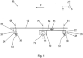
- FIG. 1 shows a schematic side view of a vehicle 10.
- the vehicle 10 is used here to transport objects in a technical system.
- the technical system is an industrial application, for example a production plant.
- the vehicle 10 is also used, for example, to deliver goods to a private recipient's home in a city or in a residential area.
- the vehicle 10 is an autonomously driving vehicle. In the illustration shown here, the vehicle 10 is on a level floor.
- the vehicle 10 comprises a vehicle frame 12 and a pendulum frame 14.
- the pendulum frame 14 can be pivoted about a pendulum axis 13 relative to the vehicle frame 12.
- the pendulum axis 13 runs in the lateral direction S.
- the vehicle frame 12 has an approximately rectangular cross-section and extends predominantly in a basic direction T and in the lateral direction S.
- the basic direction T corresponds at least approximately to the usual direction of travel F of the vehicle 10.
- the lateral direction S runs at right angles to the basic direction T.
- the basic direction T and the lateral direction S represent horizontal directions and run parallel to the flat ground on which the vehicle 10 is located.
- a vertical direction Z is perpendicular to the flat ground and thus runs perpendicular to the basic direction T and perpendicular to the lateral direction S. Every direction perpendicular to the vertical direction Z represents a horizontal direction.
- the vehicle 10 comprises four roller units 20.
- Two roller units 20 are arranged on the vehicle frame 12, offset from one another in the lateral direction S, with one of said roller units 20 being concealed in the illustration shown here.
- Two further roller units 20 are arranged on the pendulum frame 14, offset from one another in the lateral direction S, with one of said roller units 20 being concealed in the illustration shown here.
- the roller units 20 each comprise a mounting body 22, a holding body 24 and at least one wheel 30.
- the mounting bodies 22 of the roller units 20 are fastened to the vehicle frame 12 and to the pendulum frame 14.
- the holding bodies 24 and the wheels 30 can each pivot about a pivot axis 61 relative to the mounting bodies 22.
- the pivot axes 61 run, at least approximately, in the vertical direction Z.
- the holding bodies 24 of the roller units 20 can thus each pivot about a pivot axis 61 running in the vertical direction Z relative to the vehicle frame 12 and relative to the pendulum frame 14.
- the wheels 30 of the roller units 20 are each rotatable about a rotation axis 51 running in a horizontal direction relative to the holding body 24.
- the rotation axes 51 run in the lateral direction S.
- the rotation axes 51 run, for example, in the basic direction T or in another horizontal direction.
- the pivot axis 61 and the rotation axis 51 of a roller unit 20 do not intersect in the present case.
- roller units 20 each have two wheels 30.
- the two wheels 30 of a roller unit 20 can rotate about the same axis of rotation 51 and are arranged offset from one another in the direction of the axis of rotation 51.
- the vehicle 10 comprises a drive unit 70 which is arranged on the pendulum frame 14.
- the drive unit 70 comprises two drive wheels 71 which are mounted so as to be rotatable about a drive axle 73. In the illustration shown here, one of the drive wheels 71 is hidden.
- the drive unit 70 can be pivoted about a steering axis 75 relative to the pendulum frame 14.
- the drive axis 73 runs in the lateral direction S.
- the axis of rotation 51 runs, for example, in the basic direction T or in another horizontal direction.
- the roller units 20 each comprise a braking unit for braking the wheels 30.
- the wheels 30 are approximately hollow-cylindrical and each have a radially outward-facing running surface which is in contact with the ground.
- the wheels 30 also each have a radially inward-facing braking surface which cooperates with the braking unit for braking the wheels 30.
- FIG. 2 shows a section through a roller unit 20 in a first variant with an inactive brake unit.
- the roller unit 20 comprises a mounting body 22, a holding body 24 and at least one wheel 30.
- the wheel can be rotated about a rotation axis 51 relative to the holding body 24.
- the wheel 30 is not shown here.
- the mounting body 22 can be pivoted about a pivot axis 61 relative to the holding body 24 and to the wheel 30.
- the pivot axis 61 runs at right angles to the rotation axis 51.
- the roller unit 20 is moved in a direction of travel F.
- the wheel 30 rotates in a preferred direction V about the rotation axis 51.
- the roller unit 20 comprises a brake unit for braking the wheel 30.
- the holding body 24 has a pair of first bores 41 for receiving bolts 45 and a pair of second bores 42 for receiving bolts 45.
- the bores 41, 42 run parallel to the axis of rotation 51.
- the bolts 45 are circular-cylindrical. A center axis of a bolt 45, which is received in one of the bores 41, 42, thus also runs parallel to the axis of rotation 51.
- the bores 41, 42 and the bolts 45 are components of the brake unit.
- the first holes 41 are arranged diametrically opposite one another with respect to the axis of rotation 51.
- the second holes 42 are also arranged diametrically opposite one another with respect to the axis of rotation 51.
- the first holes 41 and the second holes 42 are at the same distance from the axis of rotation 51 in the radial direction.
- the first holes 41 are arranged offset from the second holes 42 in the circumferential direction with respect to the axis of rotation 51.
- a bolt 45 is accommodated in each of the first bores 41.
- the second bores 42 are free of bolts.
- the brake unit has a pair of first brake shoes 31, which are each pivotably mounted about one of the bolts 45 relative to the holding body 24 in order to generate a first braking torque.
- the brake unit has an actuating unit.
- the first brake shoes 31 can be pivoted about the bolts 45 relative to the holding body 24 in order to generate the first braking torque, such that the first brake shoes 31 come into contact with the braking surface of the wheel 30.
- the actuating unit comprises a cam disk 53, which can be rotated about the axis of rotation 51.
- the cam disk 53 has two cams that project radially outward.
- the actuating unit also comprises an actuating lever 55, which is connected to the cam disk 53.
- the actuating lever 55 can be controlled by an actuator (not shown here).
- Control of the actuating lever 55 by the actuator causes the cam disk 53 to rotate about the axis of rotation 51.
- the cams cause the first brake shoes 31 to pivot about the bolts 45, whereby the first brake shoes 31 come into contact with the braking surface of the wheel 30.
- the actuating lever 55 is not controlled and the braking unit is inactive.
- the brake unit also has a reset unit.
- the reset unit pivots the first brake shoes 31 about the bolts 45 relative to the holding body 24 in such a way that the first brake shoes 31 come out of contact with the braking surface of the wheel 30.
- the reset unit comprises two reset springs 57, which are designed as tension springs in the present case. The reset springs 57 pull the first brake shoes 31 away from the braking surface of the wheel 30.
- Figure 3 shows a section through the roller unit 20 in the first variant with activated brake unit.
- the wheel 30 is not shown here.
- the actuating lever 55 is activated, the cam disk 53 is rotated about the rotation axis 51, and the first brake shoes 31 are in contact with the braking surface of the wheel 30.
- the braking unit is thus activated.
- the first bores 41 are arranged such that when the wheel 30 rotates in the preferred direction V and when the bolts 45 are received in the first bores 41, the first brake shoes 31 run onto the braking surface of the wheel 30 when the first braking torque is generated.
- Figure 4 shows a section through a roller unit 20 in a second variant with an inactive brake unit.
- the roller unit 20 in the second variant largely corresponds to the roller unit 20 in the first variant.
- the following essentially deals with the differences between the first variant and the second variant.
- the roller unit 20 is moved in a direction of travel F.
- the wheel 30 (not shown here) rotates in a preferred direction V around the axis of rotation 51.
- the roller unit 20 in the second variant comprises the same mounting body 22, the same holding body 24 and the same wheel 30 as the roller unit 20 in the first variant.
- the holding body 24 has the same holes 41, 42 for receiving bolts 45.
- the bolts 45 are also the same.
- the brake unit of the roller unit 20 in the second variant also has the same actuating unit and the same reset unit as the brake unit of the roller unit 20 in the first variant.
- a bolt 45 is accommodated in each of the second bores 42.
- the first bores 41 are free of bolts.
- the brake unit has a pair of second brake shoes 32, which are each pivotably mounted about one of the bolts 45 relative to the holding body 24 in order to generate a second braking torque.
- the second brake shoes 32 have a different contour than the first brake shoes 31.
- Control of the actuating lever 55 by the actuator causes the cam disk 53 to rotate about the axis of rotation 51.
- the cams cause the second brake shoes 32 to pivot about the bolts 45, whereby the second brake shoes 32 come into contact with the braking surface of the wheel 30.
- the actuating lever 55 is not controlled and the braking unit is inactive.
- Figure 5 shows a section through the roller unit 20 in the second variant with activated brake unit.
- the wheel 30 is not shown here.
- the actuating lever 55 is activated, the cam disk 53 is rotated about the rotation axis 51, and the second brake shoes 31 are in contact with the braking surface of the wheel 30.
- the braking unit is thus activated.
- the second bores 42 are arranged such that when the wheel 30 rotates in the preferred direction V and when the bolts 45 are received in the second bores 42, the second brake shoes 32 run on the braking surface of the wheel 30 when the second braking torque is generated.
- the first brake shoes 31 run on the braking surface of the wheel 30 when the wheel 30 rotates in the preferred direction V during braking and thereby generate the first braking torque.
- the second brake shoes 32 run on the braking surface of the wheel 30 when the wheel 30 rotates in the preferred direction V during braking and thereby generate the second braking torque.
- the first braking torque is greater than the second braking torque, for example twice as large, when the actuating lever 55 is controlled in the same way by the actuator.
- the roller unit 20 in the second variant largely corresponds to the roller unit 20 in the first variant. Only the bolts 45 are accommodated in the other holes 41, 42 and the brake shoes 31, 32 are designed slightly differently. A roller unit 20 can thus be converted from the first variant to the second variant with little effort, namely simply by repositioning the bolts 45 and exchanging the brake shoes 31, 32. The larger first braking torque or the smaller second braking torque can thus be selected with little effort, depending on the application of the roller unit 20.
Landscapes
- Engineering & Computer Science (AREA)
- Mechanical Engineering (AREA)
- General Engineering & Computer Science (AREA)
- Braking Arrangements (AREA)
Description
- Die Erfindung betrifft eine Rolleneinheit für ein Fahrzeug, umfassend einen Haltekörper, mindestens ein um eine Drehachse relativ zu dem Haltekörper drehbares Rad und mindestens eine Bremseinheit zum Bremsen des mindestens einen Rades, wobei die Bremseinheit ein Paar von Bremsbacken aufweist, welche zur Erzeugung eines Bremsmoments jeweils um einen Bolzen relativ zu dem Haltekörper schwenkbar sind. Die Erfindung betrifft auch Fahrzeug, insbesondere ein autonom fahrendes Fahrzeug, welches mindestens eine erfindungsgemäße Rolleneinheit umfasst.
- Zum Bremsen von Rädern von Fahrzeugen sind Bremsen bekannt, mittels welchen Bremsmomente erzeugbar sind. Insbesondere sind Trommelbremsen bekannt, welche zwei Bremsbacken aufweisen, die zur Erzeugung eines Bremsmoments in Kontakt mit einer Bremsfläche gebracht werden. Die Bremsfläche ist dabei eine nach innen gerichtete Oberfläche eines hohlzylindrischen Körpers und dreht mit dem zu bremsenden Rad mit. Je nach Anordnung und Schwenkrichtung der Bremsbacken laufen diese bei der Erzeugung des Bremsmoments an der Bremsfläche auf oder ab. Mit auflaufenden Bremsbacken ist ein größeres Bremsmoment erzielbar als mit ablaufenden Bremsbacken.
- Aus der
DE 20 2014 003 033 U1 ist eine Rolle bekannt, welche eine Trommelbremse mit zwei Bremsbacken umfasst. Mittels eines Bremshebels sind die Bremsbacken in Kontakt mit einer Bremsfläche bringbar. - Aus der
DE 16 75 142 A ist eine Trommelbremse mit mehreren Bremsschuhpaaren bekannt. Die Bremsschuhe sind dabei zur Erzeugung eines Bremsmoments jeweils um einen Bolzen schwenkbar. - Aus der
EP 0 202 541 B1 ist eine Trommelbremse mit drei Bremsbacken bekannt. Dabei sind zwei Bremsbacken in Vorwärtsfahrtrichtung ablaufend gelagert, und in Rückwärtsfahrtrichtung ist ein Bremsbacken auflaufend und ein Bremsbacken ablaufend gelagert. - Der Erfindung liegt die Aufgabe zugrunde, eine Rolleneinheit für ein Fahrzeug sowie ein Fahrzeug, insbesondere ein autonom fahrendes Fahrzeug, weiterzubilden.
- Die Aufgabe wird durch eine Rolleneinheit mit den im Anspruch 1 angegebenen Merkmalen gelöst. Vorteilhafte Ausgestaltungen und Weiterbildungen sind Gegenstand der Unteransprüche. Die Aufgabe wird auch durch ein Fahrzeug mit den im Anspruch 13 angegebenen Merkmalen gelöst. Vorteilhafte Ausgestaltungen und Weiterbildungen sind Gegenstand der Unteransprüche.
- Eine erfindungsgemäße Rolleneinheit für ein Fahrzeug umfasst einen Haltekörper, mindestens ein um eine Drehachse relativ zu dem Haltekörper drehbares Rad und mindestens eine Bremseinheit zum Bremsen des mindestens einen Rades. Dabei weist die Bremseinheit ein Paar von Bremsbacken auf, welche zur Erzeugung eines Bremsmoments jeweils um einen Bolzen relativ zu dem Haltekörper schwenkbar sind. Der Haltekörper weist ein Paar von ersten Bohrungen zur Aufnahme der Bolzen auf. Der Haltekörper weist auch ein Paar von zweiten Bohrungen zur Aufnahme der Bolzen auf.
- Eine erfindungsgemäße Rolleneinheit ist, je nach gewünschtem Bremsmoment, flexibel in verschiedenen Varianten konfigurierbar. Die wesentlichen Bauteile sind, wie bei einem Baukasten, bei allen Varianten identisch. Dadurch ist nur eine verhältnismäßig geringe Varianz an Bauteilen erforderlich, wodurch die Herstellung der verschiedenen Varianten kostengünstig ist. Insbesondere sind eine Schnittstelle zur Montage an einem Fahrzeug sowie ein benötigter Bauraum und eine Traglast bei jeder Variante gleich. Auch die Ansteuerung der Bremseinheit erfolgt bei allen Varianten mit einem gleichen Aktor mit einer gleichen Betätigungskraft. Die verschiedenen Varianten entstehen einfach durch wahlweises Einsetzen der Bolzen in die ersten Bohrungen oder in die zweiten Bohrungen. Gegebenenfalls sind verschiedenartige Bremsbacken einsetzbar. Die Bremskraft ist ebenfalls über verschiedene Systemfedern einstellbar, somit sind verschiedene Anhaltecharakteristiken abbildbar.
- Vorteilhaft sind die ersten Bohrungen und die zweiten Bohrungen derart angeordnet, dass bei einer Drehung des mindestens einen Rades in eine Vorzugsrichtung bei in den ersten Bohrungen aufgenommenen Bolzen mittels der Bremsbacken ein erstes Bremsmoment erzeugbar ist, und bei in den zweiten Bohrungen aufgenommenen Bolzen mittels der Bremsbacken ein zweites Bremsmoment erzeugbar ist. Dabei ist das erste Bremsmoment größer als das zweite Bremsmoment. Damit ist das von der Bremseinheit erzeugte Bremsmoment flexibel anpassbar. Wenn ein großes Bremsmoment erforderlich ist, sind die Bolzen in die ersten Bohrungen einzusetzen. Wenn ein kleineres Bremsmoment erforderlich ist, sind die Bolzen in die zweiten Bohrungen einzusetzen. Gegebenenfalls sind auch passende Bremsbacken zu wählen.
- Gemäß einer vorteilhaften Ausgestaltung der Erfindung sind die ersten Bohrungen derart angeordnet, dass bei einer Drehung des mindestens einen Rades in die Vorzugsrichtung bei in den ersten Bohrungen aufgenommenen Bolzen die Bremsbacken bei Erzeugung des ersten Bremsmoments an einer mit dem Rad drehenden Bremsfläche auflaufen. Das erste Bremsmoment ist somit durch auflaufende Bremsbacken erzeugbar. Durch auflaufende Bremsbacken ist ein verhältnismäßig großes Bremsmoment erzeugbar.
- Gemäß einer vorteilhaften Ausgestaltung der Erfindung sind die zweiten Bohrungen derart angeordnet, dass bei einer Drehung des mindestens einen Rades in die Vorzugsrichtung bei in den zweiten Bohrungen aufgenommenen Bolzen die Bremsbacken bei Erzeugung des zweiten Bremsmoments an einer mit dem Rad drehenden Bremsfläche ablaufen. Das zweite Bremsmoment ist somit durch ablaufende Bremsbacken erzeugbar. Durch ablaufende Bremsbacken ist bei gleicher Betätigungskraft ein, im Vergleich zu auflaufenden Bremsbacken, kleineres Bremsmoment erzeugbar.
- Gemäß einer bevorzugten Ausgestaltung der Erfindung sind die ersten Bohrungen diametral gegenüberliegend bezüglich der Drehachse angeordnet, und die zweiten Bohrungen sind diametral gegenüberliegend bezüglich der Drehachse angeordnet. Somit greift in jeder Variante der Rolleneinheit das erzeugte Bremsmoment symmetrisch an einer Bremsfläche des Rades an.
- Gemäß einer vorteilhaften Ausgestaltung der Erfindung sind die ersten Bohrungen bezüglich der Drehachse in Umfangsrichtung versetzt zu den zweiten Bohrungen angeordnet. Damit ist die Montage bei allen Varianten der Rolleneinheit ähnlich.
- Vorzugsweise weisen die ersten Bohrungen und die zweiten Bohrungen in radialer Richtung einen gleichen Abstand zu der Drehachse auf. Somit ist der erforderliche Bauraum bei allen Varianten der Rolleneinheit identisch.
- Gemäß einer vorteilhaften Weiterbildung der Erfindung weist die Bremseinheit eine Betätigungseinheit auf, mittels welcher die Bremsbacken zur Erzeugung eines Bremsmoments um die Bolzen relativ zu dem Haltekörper derart schwenkbar sind, dass die Bremsbacken mit einer mit dem Rad drehenden Bremsfläche in Kontakt kommen. Die Bremseinheit wirkt somit in Form einer Trommelbremse.
- Vorzugsweise umfasst die Betätigungseinheit dabei eine Nockenscheibe, welche um die Drehachse drehbar ist, und welche zwei radial nach außen ragende Nocken aufweist.
- Gemäß einer vorteilhaften Weiterbildung der Erfindung weist die Bremseinheit eine Rückstelleinheit auf, welche die Bremsbacken derart um die Bolzen relativ zu dem Haltekörper schwenkt, dass die Bremsbacken außer Kontakt mit der mit dem Rad drehenden Bremsfläche kommen. Die Rückstelleinheit wirkt dabei selbsttätig auf die Bremsbacken. Eine aktive Rückstellung der Bremsbacken ist somit nicht erforderlich.
- Vorzugsweise umfasst die Rückstelleinheit dabei zwei Rückstellfedern, welche als Zugfedern ausgestaltet sind.
- Gemäß einer bevorzugten Ausgestaltung der Erfindung weist die Rolleneinheit einen Montagekörper auf, welcher um eine Schwenkachse relativ zu dem Haltekörper schwenkbar ist. Wenn die Rolleneinheit mit dem Montagekörper an einem Fahrzeug befestigt ist, so richtet sich der Haltekörper mit dem Rad unabhängig von einer Fahrtrichtung des Fahrzeugs stets derart aus, dass das Rad nachläuft. Unabhängig von der Fahrtrichtung dreht somit das Rad immer in die gleiche Vorzugsrichtung. Die Größe des Bremsmomentes ist unter anderem von der Laufrichtung des Rades abhängig. Wenn das Rad immer in die gleiche Vorzugsrichtung dreht, so ist das erzeugte Bremsmoment von der Fahrtrichtung unabhängig.
- Ein erfindungsgemäßes Fahrzeug, insbesondere ein autonom fahrendes Fahrzeug, umfasst einen Fahrzeugrahmen und mindestens eine erfindungsgemäße Rolleneinheit. Bei einem Fahrzeug, welches einen verhältnismäßig hohen Schwerpunkt aufweist, kann eine Bremsung mit einem zu großen Bremsmoment zu einem Umkippen des Fahrzeugs führen. Bei einem Fahrzeug, welches einen verhältnismäßig niedrigen Schwerpunkt aufweist, besteht keine Gefahr des Umkippens. Durch entsprechende Einstellung der Rolleneinheit ist dabei mit geringem Aufwand für ein Fahrzeug mit hohem Schwerpunkt das kleinere zweite Bremsmoment wählbar. Ebenso ist mit geringem Aufwand für ein Fahrzeug mit niedrigem Schwerpunkt das größere erste Bremsmoment wählbar.
- Gemäß einer bevorzugten Ausgestaltung der Erfindung ist die mindestens eine Rolleneinheit derart an dem Fahrzeugrahmen angeordnet, dass der Haltekörper um eine in Vertikalrichtung verlaufende Schwenkachse relativ zu dem Fahrzeugrahmen schwenkbar ist. Der Montagekörper ist dabei an dem Fahrzeug befestigt. Der Haltekörper mit dem Rad richtet sich unabhängig von einer Fahrtrichtung des Fahrzeugs stets derart aus, dass das Rad nachläuft. Unabhängig von der Fahrtrichtung dreht somit das Rad immer in die gleiche Vorzugsrichtung. Die Größe des Bremsmomentes ist unter anderem von der Laufrichtung des Rades abhängig. Wenn das Rad immer in die gleiche Vorzugsrichtung dreht, so ist das erzeugte Bremsmoment von der Fahrtrichtung unabhängig.
- Die Erfindung ist nur durch den Umfang der beigefügten Ansprüche beschränkt.
- Die Erfindung wird nun anhand von Abbildungen näher erläutert. Die Erfindung ist nicht auf die in den Abbildungen dargestellten Ausführungsbeispiele beschränkt. Die Abbildungen stellen den Gegenstand der Erfindung nur schematisch dar. Es zeigen:
- Figur 1:
- eine schematische Seitenansicht eines autonom fahrenden Fahrzeugs,
- Figur 2:
- einen Schnitt durch eine Rolleneinheit in einer ersten Variante mit inaktiver Bremseinheit,
- Figur 3:
- einen Schnitt durch die Rolleneinheit in der ersten Variante mit aktivierter Bremseinheit,
- Figur 4:
- einen Schnitt durch eine Rolleneinheit in einer zweiten Variante mit inaktiver Bremseinheit und
- Figur 5:
- einen Schnitt durch die Rolleneinheit in der zweiten Variante mit aktivierter Bremseinheit.
-
Figur 1 zeigt eine schematische Seitenansicht eines Fahrzeugs 10. Das Fahrzeug 10 dient vorliegend zum Transport von Gegenständen in einer technischen Anlage. Bei der technischen Anlage handelt es sich um eine industrielle Anwendung, beispielsweise ein Produktionswerk. Das Fahrzeug 10 dient beispielsweise auch zur Lieferung von Waren zu einem Wohnhaus eines privaten Empfängers in einer Stadt oder in einem Wohngebiet. Bei dem Fahrzeug 10 handelt es sich vorliegend um ein autonom fahrendes Fahrzeug. In der hier gezeigten Darstellung befindet sich das Fahrzeug 10 auf einem ebenen Boden. - Das Fahrzeug 10 umfasst einen Fahrzeugrahmen 12 und einen Pendelrahmen 14. Der Pendelrahmen 14 ist um eine Pendelachse 13 relativ zu dem Fahrzeugrahmen 12 schwenkbar. Die Pendelachse 13 verläuft in Seitenrichtung S. Der Fahrzeugrahmen 12 weist einen annähernd rechteckförmigen Querschnitt auf und erstreckt sich vorwiegend in eine Grundrichtung T und in die Seitenrichtung S.
- Die Grundrichtung T entspricht zumindest annähernd der gewöhnlichen Fahrtrichtung F des Fahrzeugs 10. Die Seitenrichtung S verläuft rechtwinklig zu der Grundrichtung T. Die Grundrichtung T und die Seitenrichtung S stellen horizontale Richtungen dar und verlaufen parallel zu dem ebenen Boden, auf welchem sich das Fahrzeug 10 befindet. Eine Vertikalrichtung Z steht senkrecht auf dem ebenen Boden und verläuft somit rechtwinklig zu der Grundrichtung T und rechtwinklig zu der Seitenrichtung S. Jede Richtung rechtwinklig zu der Vertikalrichtung Z stellt eine horizontale Richtung dar.
- Das Fahrzeug 10 umfasst vorliegend vier Rolleneinheiten 20. An dem Fahrzeugrahmen 12 sind zwei Rolleneinheiten 20 in Seitenrichtung S versetzt zueinander angeordnet, wobei in der hier gezeigten Darstellung eine der besagten Rolleneinheiten 20 verdeckt ist. An dem Pendelrahmen 14 sind zwei weitere Rolleneinheiten 20 in Seitenrichtung S versetzt zueinander angeordnet, wobei in der hier gezeigten Darstellung eine der besagten Rolleneinheiten 20 verdeckt ist.
- Die Rolleneinheiten 20 umfassen jeweils einen Montagekörper 22, einen Haltekörper 24 und mindestens ein Rad 30. Die Montagekörper 22 der Rolleneinheiten 20 sind an dem Fahrzeugrahmen 12 sowie an dem Pendelrahmen 14 befestigt. Die Haltekörper 24 und die Räder 30 sind dabei jeweils um eine Schwenkachse 61 relativ zu den Montagekörpern 22 schwenkbar. Die Schwenkachsen 61 verlaufen, zumindest annähernd, in Vertikalrichtung Z. Die Haltekörper 24 der Rolleneinheiten 20 sind somit jeweils um eine in Vertikalrichtung Z verlaufende Schwenkachse 61 relativ zu dem Fahrzeugrahmen 12 sowie relativ zu dem Pendelrahmen 14 schwenkbar.
- Die Räder 30 der Rolleneinheiten 20 sind jeweils um eine in eine horizontale Richtung verlaufende Drehachse 51 relativ zu dem Haltekörper 24 drehbar. In der hier gezeigten Darstellung verlaufen die Drehachsen 51 in Seitenrichtung S. In Abhängigkeit von einer Schwenkung der Haltekörper 24 um die Schwenkachsen 61 verlaufen die Drehachsen 51 beispielsweise in Grundrichtung T oder in eine andere horizontale Richtung. Die Schwenkachse 61 und die Drehachse 51 einer Rolleneinheiten 20 schneiden sich vorliegend nicht.
- Es ist denkbar, dass die Rolleneinheiten 20 jeweils zwei Räder 30 aufweisen. Die beiden Räder 30 einer Rolleneinheit 20 sind in diesem Fall um die gleiche Drehachse 51 drehbar und sind in Richtung der Drehachse 51 versetzt zueinander angeordnet.
- Das Fahrzeug 10 umfasst eine Antriebseinheit 70, die an dem Pendelrahmen 14 angeordnet ist. Die Antriebseinheit 70 umfasst zwei Antriebsräder 71, welche um eine Antriebsachse 73 drehbar gelagert sind. In der hier gezeigten Darstellung ist eines der Antriebsräder 71 verdeckt.
- Die Antriebseinheit 70 ist um eine Lenkachse 75 relativ zu dem Pendelrahmen 14 schwenkbar. In der hier gezeigten Darstellung verläuft die Antriebsachse 73 in Seitenrichtung S. In Abhängigkeit von einer Schwenkung der Antriebseinheit 70 um die Lenkachse 75 verläuft die Drehachse 51 beispielsweise in Grundrichtung T oder in eine andere horizontale Richtung.
- Die Rolleneinheiten 20 umfassen jeweils eine Bremseinheit zum Bremsen der Räder 30. Die Räder 30 sind annähernd hohlzylindrisch ausgebildet und weisen jeweils eine radial nach außen gerichtete Lauffläche auf, welche in Kontakt mit dem Boden steht. Die Räder 30 weisen ferner jeweils eine radial nach innen gerichtete Bremsfläche auf, welche mit der Bremseinheit zum Bremsen der Räder 30 zusammenwirkt.
-
Figur 2 zeigt einen Schnitt durch eine Rolleneinheit 20 in einer ersten Variante mit inaktiver Bremseinheit. Wie bereits erwähnt umfasst die Rolleneinheit 20 einen Montagekörper 22, einen Haltekörper 24 und mindestens ein Rad 30. Das Rad ist um eine Drehachse 51 relativ zu dem Haltekörper 24 drehbar. Das Rad 30 ist hier nicht dargestellt. Der Montagekörper 22 ist relativ zu dem Haltekörper 24 und zu dem Rad 30 um eine Schwenkachse 61 schwenkbar. Die Schwenkachse 61 verläuft rechtwinklig zu der Drehachse 51. Die Rolleneinheit 20 wird in eine Fahrtrichtung F bewegt. Dabei dreht sich das Rad 30 in eine Vorzugsrichtung V um die Drehachse 51. - Die Rolleneinheit 20 umfasst eine Bremseinheit zum Bremsen des Rades 30. Der Haltekörper 24 weist dazu ein Paar von ersten Bohrungen 41 zur Aufnahme von Bolzen 45 und ein Paar von zweiten Bohrungen 42 zur Aufnahme von Bolzen 45 auf. Die Bohrungen 41, 42 verlaufen parallel zu der Drehachse 51. Die Bolzen 45 sind kreiszylindrisch ausgebildet. Eine Mittelachse eines Bolzens 45, der in einer der Bohrungen 41, 42 aufgenommen ist, verläuft somit ebenfalls parallel zu der Drehachse 51. Die Bohrungen 41, 42 und die Bolzen 45 sind Bestandteile der Bremseinheit.
- Die ersten Bohrungen 41 sind diametral gegenüberliegend bezüglich der Drehachse 51 angeordnet. Auch die zweiten Bohrungen 42 sind diametral gegenüberliegend bezüglich der Drehachse 51 angeordnet. Die ersten Bohrungen 41 und die zweiten Bohrungen 42weisen in radialer Richtung einen gleichen Abstand zu der Drehachse 51 auf. Die ersten Bohrungen 41 sind bezüglich der Drehachse 51 in Umfangsrichtung versetzt zu den zweiten Bohrungen 42 angeordnet.
- In der hier gezeigten ersten Variante der Rolleneinheit 20 ist in den ersten Bohrungen 41 jeweils ein Bolzen 45 aufgenommen. Die zweiten Bohrungen 42 sind frei von Bolzen. Die Bremseinheit weist ein Paar von ersten Bremsbacken 31 auf, welche zur Erzeugung eines ersten Bremsmoments jeweils um einen der Bolzen 45 relativ zu dem Haltekörper 24 schwenkbar gelagert sind.
- Die Bremseinheit weist eine Betätigungseinheit auf. Mittels der Betätigungseinheit sind die ersten Bremsbacken 31 zur Erzeugung des ersten Bremsmoments um die Bolzen 45 relativ zu dem Haltekörper 24 derart schwenkbar, dass die ersten Bremsbacken 31 mit der Bremsfläche des Rades 30 in Kontakt kommen. Die Betätigungseinheit umfasst eine Nockenscheibe 53, welche um die Drehachse 51 drehbar ist. Die Nockenscheibe 53 weist zwei radial nach außen ragende Nocken auf. Die Betätigungseinheit umfasst auch einen Betätigungshebel 55, welcher mit der Nockenscheibe 53 verbunden ist. Der Betätigungshebel 55 ist von einem hier nicht dargestellten Aktor ansteuerbar.
- Eine Ansteuerung des Betätigungshebels 55 durch den Aktor bewirkt eine Drehung der Nockenscheibe 53 um die Drehachse 51. Bei einer solchen Drehung der Nockenscheibe 53 um die Drehachse 51 verursachen die Nocken die besagte Schwenkung der ersten Bremsbacken 31 um die Bolzen 45, wodurch die ersten Bremsbacken 31 mit der Bremsfläche des Rades 30 in Kontakt kommen. In der hier gezeigten Darstellung ist der Betätigungshebel 55 nicht angesteuert, und die Bremseinheit ist inaktiv.
- Die Bremseinheit weist auch eine Rückstelleinheit auf. Die Rückstelleinheit schwenkt die ersten Bremsbacken 31 derart um die Bolzen 45 relativ zu dem Haltekörper 24, dass die ersten Bremsbacken 31 außer Kontakt mit der Bremsfläche des Rades 30 kommen. Die Rückstelleinheit umfasst zwei Rückstellfedern 57, welche vorliegend als Zugfedern ausgestaltet sind. Die Rückstellfedern 57 ziehen die ersten Bremsbacken 31 von der Bremsfläche des Rades 30 weg.
-
Figur 3 zeigt einen Schnitt durch die Rolleneinheit 20 in der ersten Variante mit aktivierter Bremseinheit. Das Rad 30 ist hier nicht dargestellt. Im Unterschied zur Darstellung inFigur 2 ist der Betätigungshebel 55 angesteuert, die Nockenscheibe 53 ist um die Drehachse 51 gedreht, und die ersten Bremsbacken 31 sind mit der Bremsfläche des Rades 30 in Kontakt. Die Bremseinheit ist somit aktiviert. - Die ersten Bohrungen 41 sind derart angeordnet, dass bei einer Drehung des Rades 30 in die Vorzugsrichtung V und bei in den ersten Bohrungen 41 aufgenommenen Bolzen 45 die ersten Bremsbacken 31 bei Erzeugung des ersten Bremsmoments an der Bremsfläche des Rades 30 auflaufen.
-
Figur 4 zeigt einen Schnitt durch eine Rolleneinheit 20 in einer zweiten Variante mit inaktiver Bremseinheit. Die Rolleneinheit 20 in der zweiten Variante entspricht weitgehend der Rolleneinheit 20 in der ersten Variante. Im Folgenden wird im Wesentlichen auf die Unterschiede zwischen der ersten Variante und der zweiten Variante eingegangen. Die Rolleneinheit 20 wird in eine Fahrtrichtung F bewegt. Dabei dreht sich das hier nicht dargestellte Rad 30 in eine Vorzugsrichtung V um die Drehachse 51. - Die Rolleneinheit 20 in der zweiten Variante umfasst den gleichen Montagekörper 22, den gleichen Haltekörper 24 und das gleiche Rad 30 wie die Rolleneinheit 20 in der ersten Variante. Der Haltekörper 24 weist dabei die gleichen Bohrungen 41, 42 zur Aufnahme von Bolzen 45 auf. Auch die Bolzen 45 sind gleich. Die Bremseinheit der Rolleneinheit 20 in der zweiten Variante weist ferner die gleiche Betätigungseinheit sowie die gleiche Rückstelleinheit auf wie die Bremseinheit der Rolleneinheit 20 in der ersten Variante.
- In der hier gezeigten zweiten Variante der Rolleneinheit 20 ist, abweichend von der Rolleneinheit 20 in der ersten Variante, in den zweiten Bohrungen 42 jeweils ein Bolzen 45 aufgenommen. Die ersten Bohrungen 41 sind frei von Bolzen. Die Bremseinheit weist ein Paar von zweiten Bremsbacken 32 auf, welche zur Erzeugung eines zweiten Bremsmoments jeweils um einen der Bolzen 45 relativ zu dem Haltekörper 24 schwenkbar gelagert sind. Die zweiten Bremsbacken 32 weisen vorliegend eine andere Kontur auf als die ersten Bremsbacken 31.
- Eine Ansteuerung des Betätigungshebels 55 durch den hier nicht dargestellten Aktor bewirkt eine Drehung der Nockenscheibe 53 um die Drehachse 51. Bei einer solchen Drehung der Nockenscheibe 53 um die Drehachse 51 verursachen die Nocken eine Schwenkung der zweiten Bremsbacken 32 um die Bolzen 45, wodurch die zweiten Bremsbacken 32 mit der Bremsfläche des Rades 30 in Kontakt kommen. In der hier gezeigten Darstellung ist der Betätigungshebel 55 nicht angesteuert, und die Bremseinheit ist inaktiv.
-
Figur 5 zeigt einen Schnitt durch die Rolleneinheit 20 in der zweiten Variante mit aktivierter Bremseinheit. Das Rad 30 ist hier nicht dargestellt. Im Unterschied zur Darstellung inFigur 4 ist der Betätigungshebel 55 angesteuert, die Nockenscheibe 53 ist um die Drehachse 51 gedreht, und die zweiten Bremsbacken 31 sind mit der Bremsfläche des Rades 30 in Kontakt. Die Bremseinheit ist somit aktiviert. - Die zweiten Bohrungen 42 sind derart angeordnet, dass bei einer Drehung des Rades 30 in die Vorzugsrichtung V und bei in den zweiten Bohrungen 42 aufgenommenen Bolzen 45 die zweiten Bremsbacken 32 bei Erzeugung des zweiten Bremsmoments an der Bremsfläche des Rades 30 ablaufen.
- Bei der Rolleneinheit 20 in der ersten Variante laufen die ersten Bremsbacken 31 bei einer Drehung des Rades 30 in die Vorzugsrichtung V beim Bremsen an der Bremsfläche des Rades 30 auf und erzeugen dabei das erste Bremsmoment. Bei der Rolleneinheit 20 in der zweiten Variante laufen die zweiten Bremsbacken 32 bei einer Drehung des Rades 30 in die Vorzugsrichtung V beim Bremsen an der Bremsfläche des Rades 30 ab und erzeugen dabei das zweite Bremsmoment. Das erste Bremsmoment ist dabei, bei gleichartiger Ansteuerung des Betätigungshebels 55 durch den Aktor, größer als das zweite Bremsmoment, beispielsweise doppelt so groß.
- Die Rolleneinheit 20 in der zweiten Variante entspricht, wie bereits erwähnt, weitgehend der Rolleneinheit 20 in der ersten Variante. Lediglich sind die Bolzen 45 in den anderen Bohrungen 41, 42 aufgenommen, und die Bremsbacken 31, 32 sind geringfügig unterschiedlich ausgestaltet. Eine Rolleneinheit 20 ist somit mit geringem Aufwand, nämlich lediglich durch Umstecken der Bolzen 45 und durch Austauschen der Bremsbacken 31, 32 von der ersten Variante auf die zweite Variante umrüstbar. Somit ist mit geringen Aufwand das größere erste Bremsmoment oder das kleinere zweite Bremsmoment, je nach Anwendung der Rolleneinheit 20, wählbar.
-
- 10
- Fahrzeug
- 12
- Fahrzeugrahmen
- 13
- Pendelachse
- 14
- Pendelrahmen
- 20
- Rolleneinheit
- 22
- Montagekörper
- 24
- Haltekörper
- 30
- Rad
- 31
- erster Bremsbacken
- 32
- zweiter Bremsbacken
- 41
- erste Bohrung
- 42
- zweite Bohrung
- 45
- Bolzen
- 51
- Drehachse
- 53
- Nockenscheibe
- 55
- Betätigungshebel
- 57
- Rückstellfeder
- 61
- Schwenkachse
- 70
- Antriebseinheit
- 71
- Antriebsrad
- 73
- Antriebsachse
- 75
- Lenkachse
- F
- Fahrtrichtung
- S
- Seitenrichtung
- T
- Grundrichtung
- V
- Vorzugsrichtung
- Z
- Vertikalrichtung
Claims (14)
- Rolleneinheit (20) für ein Fahrzeug (10), umfassendeinen Haltekörper (24),mindestens ein um eine Drehachse (51) relativ zu dem Haltekörper (24) drehbares Rad (30) undmindestens eine Bremseinheit zum Bremsen des mindestens einen Rades (30),wobei die Bremseinheitein Paar von Bremsbacken (31, 32) aufweist, welche zur Erzeugung eines Bremsmoments jeweils um einen Bolzen (45) relativ zu dem Haltekörper (24) schwenkbar sind, wobeider Haltekörper (24) ein Paar von ersten Bohrungen (41) zur Aufnahme der Bolzen (45) aufweist,dadurch gekennzeichnet, dassder Haltekörper (24) ein Paar von zweiten Bohrungen (42) zur Aufnahme der Bolzen (45) aufweist.
- Rolleneinheit (20) nach Anspruch 1,
dadurch gekennzeichnet, dassdie ersten Bohrungen (41) und die zweiten Bohrungen (42) derart angeordnet sind, dass bei einer Drehung des mindestens einen Rades (30) in eine Vorzugsrichtung (V)bei in den ersten Bohrungen (41) aufgenommenen Bolzen (45) mittels der Bremsbacken (31) ein erstes Bremsmoment erzeugbar ist, undbei in den zweiten Bohrungen (42) aufgenommenen Bolzen (45) mittels der Bremsbacken (32) ein zweites Bremsmoment erzeugbar ist,wobei das erste Bremsmoment größer ist als das zweite Bremsmoment. - Rolleneinheit (20) nach Anspruch 2,
dadurch gekennzeichnet, dassdie ersten Bohrungen (41) derart angeordnet sind, dassbei einer Drehung des mindestens einen Rades (30) in die Vorzugsrichtung (V) bei in den ersten Bohrungen (41) aufgenommenen Bolzen (45)die Bremsbacken (31) bei Erzeugung des ersten Bremsmoments an einer mit dem Rad (30) drehenden Bremsfläche auflaufen. - Rolleneinheit (20) nach einem der Ansprüche 2 bis 3,
dadurch gekennzeichnet, dassdie zweiten Bohrungen (42) derart angeordnet sind, dassbei einer Drehung des mindestens einen Rades (30) in die Vorzugsrichtung (V) bei in den zweiten Bohrungen (42) aufgenommenen Bolzen (45)die Bremsbacken (32) bei Erzeugung des zweiten Bremsmoments an einer mit dem Rad (30) drehenden Bremsfläche ablaufen. - Rolleneinheit (20) nach mindestens einem der vorangegangenen Ansprüche,
dadurch gekennzeichnet, dassdie ersten Bohrungen (41) diametral gegenüberliegend bezüglich der Drehachse (51) angeordnet sind, und dassdie zweiten Bohrungen (42) diametral gegenüberliegend bezüglich der Drehachse (51) angeordnet sind. - Rolleneinheit (20) nach mindestens einem der vorangegangenen Ansprüche,
dadurch gekennzeichnet, dass
die ersten Bohrungen (41) bezüglich der Drehachse (51) in Umfangsrichtung versetzt zu den zweiten Bohrungen (42) angeordnet sind. - Rolleneinheit (20) nach mindestens einem der vorangegangenen Ansprüche,
dadurch gekennzeichnet, dass
die ersten Bohrungen (41) und die zweiten Bohrungen (42) in radialer Richtung einen gleichen Abstand zu der Drehachse (51) aufweisen. - Rolleneinheit (20) nach mindestens einem der vorangegangenen Ansprüche,
dadurch gekennzeichnet, dass
die Bremseinheit eine Betätigungseinheit aufweist, mittels welcher die Bremsbacken (31, 32) zur Erzeugung eines Bremsmoments um die Bolzen (45) relativ zu dem Haltekörper (24) derart schwenkbar sind, dass die Bremsbacken (31, 32) mit einer mit dem Rad (30) drehenden Bremsfläche in Kontakt kommen. - Rolleneinheit (20) nach Anspruch 8,
dadurch gekennzeichnet, dass
die Betätigungseinheit eine Nockenscheibe (53) umfasst, welche um die Drehachse (51) drehbar ist, und welche zwei radial nach außen ragende Nocken aufweist. - Rolleneinheit (20) nach mindestens einem der vorangegangenen Ansprüche,
dadurch gekennzeichnet, dass
die Bremseinheit eine Rückstelleinheit aufweist, welche die Bremsbacken (31, 32) derart um die Bolzen (45) relativ zu dem Haltekörper (24) schwenkt, dass die Bremsbacken (31, 32) außer Kontakt mit der mit dem Rad (30) drehenden Bremsfläche kommen. - Rolleneinheit (20) nach Anspruch 10,
dadurch gekennzeichnet, dass
die Rückstelleinheit zwei Rückstellfedern (57) umfasst, welche als Zugfedern ausgestaltet sind. - Rolleneinheit (20) nach mindestens einem der vorangegangenen Ansprüche,
dadurch gekennzeichnet, dass
die Rolleneinheit (20) einen Montagekörper (22) aufweist, welcher um eine Schwenkachse (61) relativ zu dem Haltekörper (24) schwenkbar ist. - Fahrzeug (10), insbesondere autonom fahrendes Fahrzeug, umfassendeinen Fahrzeugrahmen (12) undmindestens eine Rolleneinheit (20) nach einem der vorangegangenen Ansprüche.
- Fahrzeug (10) nach Anspruch 13,
dadurch gekennzeichnet, dassdie mindestens eine Rolleneinheit (20) derart an dem Fahrzeugrahmen (12) angeordnet ist, dassder Haltekörper (24) um eine in Vertikalrichtung (Z) verlaufende Schwenkachse (61) relativ zu dem Fahrzeugrahmen (12) schwenkbar ist.
Applications Claiming Priority (2)
| Application Number | Priority Date | Filing Date | Title |
|---|---|---|---|
| DE102020005296.7A DE102020005296B3 (de) | 2020-08-28 | 2020-08-28 | Rolleneinheit für ein Fahrzeug und Fahrzeug |
| PCT/EP2021/069516 WO2022042930A1 (de) | 2020-08-28 | 2021-07-13 | Rolleneinheit für ein fahrzeug und fahrzeug |
Publications (3)
| Publication Number | Publication Date |
|---|---|
| EP4204706A1 EP4204706A1 (de) | 2023-07-05 |
| EP4204706B1 true EP4204706B1 (de) | 2024-09-11 |
| EP4204706C0 EP4204706C0 (de) | 2024-09-11 |
Family
ID=76854245
Family Applications (1)
| Application Number | Title | Priority Date | Filing Date |
|---|---|---|---|
| EP21742410.0A Active EP4204706B1 (de) | 2020-08-28 | 2021-07-13 | Rolleneinheit für ein fahrzeug und fahrzeug |
Country Status (3)
| Country | Link |
|---|---|
| EP (1) | EP4204706B1 (de) |
| DE (2) | DE102020005296B3 (de) |
| WO (1) | WO2022042930A1 (de) |
Families Citing this family (1)
| Publication number | Priority date | Publication date | Assignee | Title |
|---|---|---|---|---|
| DE102024116654A1 (de) * | 2024-06-13 | 2025-12-18 | Blickle Räder + Rollen GmbH u. Co. KG | Bremsvorrichtung für Rolle, Rolle und Transportwagen |
Family Cites Families (7)
| Publication number | Priority date | Publication date | Assignee | Title |
|---|---|---|---|---|
| US2365715A (en) | 1942-01-05 | 1944-12-26 | Mattersdorf Gustav | Friction brake |
| GB1161197A (en) | 1967-03-16 | 1969-08-13 | Girling Ltd | Improvements in and relating to Vehicle Drum Brakes. |
| DE2516468A1 (de) * | 1975-04-15 | 1976-10-28 | Haefele Kg | Laufrolle fuer moebelfuesse |
| US4157747A (en) * | 1978-04-13 | 1979-06-12 | Fruehauf Corporation | Brake assembly |
| DE8514496U1 (de) | 1985-05-15 | 1986-09-11 | Lucas Industries P.L.C., Birmingham, West Midlands | Trommelbremse mit drei Bremsbacken |
| DE202014003033U1 (de) | 2014-04-09 | 2015-07-31 | Blickle Räder + Rollen GmbH u. Co. KG | Rolle mit einer Bremse |
| DE202015000702U1 (de) * | 2015-01-30 | 2016-05-04 | Solo Kleinmotoren Gmbh | Momentgesteuerte Bremseinrichtung für angetriebene Werkzeuge |
-
2020
- 2020-08-28 DE DE102020005296.7A patent/DE102020005296B3/de active Active
-
2021
- 2021-07-13 WO PCT/EP2021/069516 patent/WO2022042930A1/de not_active Ceased
- 2021-07-13 DE DE102021003577.1A patent/DE102021003577A1/de active Pending
- 2021-07-13 EP EP21742410.0A patent/EP4204706B1/de active Active
Also Published As
| Publication number | Publication date |
|---|---|
| WO2022042930A1 (de) | 2022-03-03 |
| EP4204706C0 (de) | 2024-09-11 |
| EP4204706A1 (de) | 2023-07-05 |
| DE102020005296B3 (de) | 2021-08-05 |
| DE102021003577A1 (de) | 2022-03-03 |
Similar Documents
| Publication | Publication Date | Title |
|---|---|---|
| EP2019935B1 (de) | Scheibenbremse sowie belagträger und druckplatte für eine solche scheibenbremse | |
| DE102009009028B4 (de) | Geräterad | |
| DE69301391T2 (de) | Verbesserter S-Nocken für Trommelbremse | |
| EP1161356A1 (de) | Stabilisatoranordnung für das fahrwerk eines fahrzeuges | |
| DE102007054823A1 (de) | Verstellvorrichtung für Radaufhängungen | |
| DE112007001178B4 (de) | Hebelsystem zur Betätigung einer Kupplung | |
| DE102017109147A1 (de) | Aktor einer Vorrichtung zur Niveauverstellung eines Kraftfahrzeugs | |
| EP3057825B1 (de) | Drehvorrichtung für einen fahrzeugsitz und fahrzeugsitz | |
| WO2018077752A1 (de) | Vorrichtung zur horizontalen mittenrückstellung eines kupplungsschafts | |
| DE102018128771A1 (de) | Bremssystem, Achsträgereinheit für ein Fahrzeug, Fahrzeug mit einer derartigen Achsträgereinheit und Antriebseinheit | |
| DE102020005296B3 (de) | Rolleneinheit für ein Fahrzeug und Fahrzeug | |
| DE102009027081A1 (de) | Vorrichtung zur Lagerung von Bremsbacken einer Trommelbremse | |
| EP3478984A1 (de) | Achsenend-baugruppe mit einer radnabeneinheit und einer radbremse | |
| EP1451025A1 (de) | Radlagerung an einem achskörper für fahrzeuge | |
| EP3710717B1 (de) | Bremsanordnung für ein nutzfahrzeug | |
| DE102005017746B4 (de) | Einbauanordnung für Antriebswellen in Kreuzgelenkgabeln | |
| DE3624089A1 (de) | Feststellvorrichtung fuer lenkrollen von insbesondere muellcontainern | |
| DE3031891A1 (de) | Selbsttaetige nachstellvorrichtung fuer trommelbremsen | |
| EP3180536A1 (de) | Achsflansch und bremsträger | |
| DE69517190T2 (de) | Gleitschutzvorrichtung | |
| DE2313493B2 (de) | Mechanische Betätigungsvorrichtung für eine Simplex-Trommelbremse | |
| DE102015113156B4 (de) | Aktiver Radträger für ein Fahrzeug und Fahrwerk für ein Kraftfahrzeug sowie Fahrzeug | |
| DE20310256U1 (de) | Scheibenbremse für leichte Baufahrzeuge etc. mit Differentialgetriebe | |
| DE4034271A1 (de) | Felgenbremse fuer ein fahrrad | |
| DE1450146B1 (de) | Scheibenbremse für Fahrzeuge |
Legal Events
| Date | Code | Title | Description |
|---|---|---|---|
| STAA | Information on the status of an ep patent application or granted ep patent |
Free format text: STATUS: UNKNOWN |
|
| STAA | Information on the status of an ep patent application or granted ep patent |
Free format text: STATUS: THE INTERNATIONAL PUBLICATION HAS BEEN MADE |
|
| PUAI | Public reference made under article 153(3) epc to a published international application that has entered the european phase |
Free format text: ORIGINAL CODE: 0009012 |
|
| STAA | Information on the status of an ep patent application or granted ep patent |
Free format text: STATUS: REQUEST FOR EXAMINATION WAS MADE |
|
| 17P | Request for examination filed |
Effective date: 20230328 |
|
| AK | Designated contracting states |
Kind code of ref document: A1 Designated state(s): AL AT BE BG CH CY CZ DE DK EE ES FI FR GB GR HR HU IE IS IT LI LT LU LV MC MK MT NL NO PL PT RO RS SE SI SK SM TR |
|
| DAV | Request for validation of the european patent (deleted) | ||
| DAX | Request for extension of the european patent (deleted) | ||
| GRAP | Despatch of communication of intention to grant a patent |
Free format text: ORIGINAL CODE: EPIDOSNIGR1 |
|
| STAA | Information on the status of an ep patent application or granted ep patent |
Free format text: STATUS: GRANT OF PATENT IS INTENDED |
|
| INTG | Intention to grant announced |
Effective date: 20240320 |
|
| GRAS | Grant fee paid |
Free format text: ORIGINAL CODE: EPIDOSNIGR3 |
|
| GRAA | (expected) grant |
Free format text: ORIGINAL CODE: 0009210 |
|
| STAA | Information on the status of an ep patent application or granted ep patent |
Free format text: STATUS: THE PATENT HAS BEEN GRANTED |
|
| AK | Designated contracting states |
Kind code of ref document: B1 Designated state(s): AL AT BE BG CH CY CZ DE DK EE ES FI FR GB GR HR HU IE IS IT LI LT LU LV MC MK MT NL NO PL PT RO RS SE SI SK SM TR |
|
| REG | Reference to a national code |
Ref country code: GB Ref legal event code: FG4D Free format text: NOT ENGLISH |
|
| REG | Reference to a national code |
Ref country code: CH Ref legal event code: EP |
|
| REG | Reference to a national code |
Ref country code: DE Ref legal event code: R096 Ref document number: 502021005133 Country of ref document: DE |
|
| REG | Reference to a national code |
Ref country code: IE Ref legal event code: FG4D Free format text: LANGUAGE OF EP DOCUMENT: GERMAN |
|
| U01 | Request for unitary effect filed |
Effective date: 20240920 |
|
| U07 | Unitary effect registered |
Designated state(s): AT BE BG DE DK EE FI FR IT LT LU LV MT NL PT RO SE SI Effective date: 20241014 |
|
| PG25 | Lapsed in a contracting state [announced via postgrant information from national office to epo] |
Ref country code: NO Free format text: LAPSE BECAUSE OF FAILURE TO SUBMIT A TRANSLATION OF THE DESCRIPTION OR TO PAY THE FEE WITHIN THE PRESCRIBED TIME-LIMIT Effective date: 20241211 |
|
| PG25 | Lapsed in a contracting state [announced via postgrant information from national office to epo] |
Ref country code: GR Free format text: LAPSE BECAUSE OF FAILURE TO SUBMIT A TRANSLATION OF THE DESCRIPTION OR TO PAY THE FEE WITHIN THE PRESCRIBED TIME-LIMIT Effective date: 20241212 |
|
| PG25 | Lapsed in a contracting state [announced via postgrant information from national office to epo] |
Ref country code: HR Free format text: LAPSE BECAUSE OF FAILURE TO SUBMIT A TRANSLATION OF THE DESCRIPTION OR TO PAY THE FEE WITHIN THE PRESCRIBED TIME-LIMIT Effective date: 20240911 |
|
| PG25 | Lapsed in a contracting state [announced via postgrant information from national office to epo] |
Ref country code: ES Free format text: LAPSE BECAUSE OF FAILURE TO SUBMIT A TRANSLATION OF THE DESCRIPTION OR TO PAY THE FEE WITHIN THE PRESCRIBED TIME-LIMIT Effective date: 20240911 Ref country code: RS Free format text: LAPSE BECAUSE OF FAILURE TO SUBMIT A TRANSLATION OF THE DESCRIPTION OR TO PAY THE FEE WITHIN THE PRESCRIBED TIME-LIMIT Effective date: 20241211 |
|
| PG25 | Lapsed in a contracting state [announced via postgrant information from national office to epo] |
Ref country code: RS Free format text: LAPSE BECAUSE OF FAILURE TO SUBMIT A TRANSLATION OF THE DESCRIPTION OR TO PAY THE FEE WITHIN THE PRESCRIBED TIME-LIMIT Effective date: 20241211 Ref country code: NO Free format text: LAPSE BECAUSE OF FAILURE TO SUBMIT A TRANSLATION OF THE DESCRIPTION OR TO PAY THE FEE WITHIN THE PRESCRIBED TIME-LIMIT Effective date: 20241211 Ref country code: HR Free format text: LAPSE BECAUSE OF FAILURE TO SUBMIT A TRANSLATION OF THE DESCRIPTION OR TO PAY THE FEE WITHIN THE PRESCRIBED TIME-LIMIT Effective date: 20240911 Ref country code: GR Free format text: LAPSE BECAUSE OF FAILURE TO SUBMIT A TRANSLATION OF THE DESCRIPTION OR TO PAY THE FEE WITHIN THE PRESCRIBED TIME-LIMIT Effective date: 20241212 Ref country code: ES Free format text: LAPSE BECAUSE OF FAILURE TO SUBMIT A TRANSLATION OF THE DESCRIPTION OR TO PAY THE FEE WITHIN THE PRESCRIBED TIME-LIMIT Effective date: 20240911 |
|
| PG25 | Lapsed in a contracting state [announced via postgrant information from national office to epo] |
Ref country code: IS Free format text: LAPSE BECAUSE OF FAILURE TO SUBMIT A TRANSLATION OF THE DESCRIPTION OR TO PAY THE FEE WITHIN THE PRESCRIBED TIME-LIMIT Effective date: 20250111 |
|
| PG25 | Lapsed in a contracting state [announced via postgrant information from national office to epo] |
Ref country code: SM Free format text: LAPSE BECAUSE OF FAILURE TO SUBMIT A TRANSLATION OF THE DESCRIPTION OR TO PAY THE FEE WITHIN THE PRESCRIBED TIME-LIMIT Effective date: 20240911 |
|
| PG25 | Lapsed in a contracting state [announced via postgrant information from national office to epo] |
Ref country code: PL Free format text: LAPSE BECAUSE OF FAILURE TO SUBMIT A TRANSLATION OF THE DESCRIPTION OR TO PAY THE FEE WITHIN THE PRESCRIBED TIME-LIMIT Effective date: 20240911 Ref country code: CZ Free format text: LAPSE BECAUSE OF FAILURE TO SUBMIT A TRANSLATION OF THE DESCRIPTION OR TO PAY THE FEE WITHIN THE PRESCRIBED TIME-LIMIT Effective date: 20240911 |
|
| PG25 | Lapsed in a contracting state [announced via postgrant information from national office to epo] |
Ref country code: SK Free format text: LAPSE BECAUSE OF FAILURE TO SUBMIT A TRANSLATION OF THE DESCRIPTION OR TO PAY THE FEE WITHIN THE PRESCRIBED TIME-LIMIT Effective date: 20240911 |
|
| PGFP | Annual fee paid to national office [announced via postgrant information from national office to epo] |
Ref country code: GB Payment date: 20250529 Year of fee payment: 5 |
|
| PLBE | No opposition filed within time limit |
Free format text: ORIGINAL CODE: 0009261 |
|
| STAA | Information on the status of an ep patent application or granted ep patent |
Free format text: STATUS: NO OPPOSITION FILED WITHIN TIME LIMIT |
|
| 26N | No opposition filed |
Effective date: 20250612 |
|
| U20 | Renewal fee for the european patent with unitary effect paid |
Year of fee payment: 5 Effective date: 20250731 |
|
| REG | Reference to a national code |
Ref country code: CH Ref legal event code: H13 Free format text: ST27 STATUS EVENT CODE: U-0-0-H10-H13 (AS PROVIDED BY THE NATIONAL OFFICE) Effective date: 20260224 |
|
| PG25 | Lapsed in a contracting state [announced via postgrant information from national office to epo] |
Ref country code: CH Free format text: LAPSE BECAUSE OF NON-PAYMENT OF DUE FEES Effective date: 20250731 |