EP4202285A1 - Cuve de stockage de gaz liquéfié - Google Patents
Cuve de stockage de gaz liquéfié Download PDFInfo
- Publication number
- EP4202285A1 EP4202285A1 EP22214632.6A EP22214632A EP4202285A1 EP 4202285 A1 EP4202285 A1 EP 4202285A1 EP 22214632 A EP22214632 A EP 22214632A EP 4202285 A1 EP4202285 A1 EP 4202285A1
- Authority
- EP
- European Patent Office
- Prior art keywords
- tank
- tower
- sump
- center
- bottom wall
- Prior art date
- Legal status (The legal status is an assumption and is not a legal conclusion. Google has not performed a legal analysis and makes no representation as to the accuracy of the status listed.)
- Pending
Links
Images


Classifications
-
- F—MECHANICAL ENGINEERING; LIGHTING; HEATING; WEAPONS; BLASTING
- F17—STORING OR DISTRIBUTING GASES OR LIQUIDS
- F17C—VESSELS FOR CONTAINING OR STORING COMPRESSED, LIQUEFIED OR SOLIDIFIED GASES; FIXED-CAPACITY GAS-HOLDERS; FILLING VESSELS WITH, OR DISCHARGING FROM VESSELS, COMPRESSED, LIQUEFIED, OR SOLIDIFIED GASES
- F17C3/00—Vessels not under pressure
- F17C3/02—Vessels not under pressure with provision for thermal insulation
-
- B—PERFORMING OPERATIONS; TRANSPORTING
- B63—SHIPS OR OTHER WATERBORNE VESSELS; RELATED EQUIPMENT
- B63B—SHIPS OR OTHER WATERBORNE VESSELS; EQUIPMENT FOR SHIPPING
- B63B25/00—Load-accommodating arrangements, e.g. stowing, trimming; Vessels characterised thereby
- B63B25/02—Load-accommodating arrangements, e.g. stowing, trimming; Vessels characterised thereby for bulk goods
- B63B25/08—Load-accommodating arrangements, e.g. stowing, trimming; Vessels characterised thereby for bulk goods fluid
- B63B25/12—Load-accommodating arrangements, e.g. stowing, trimming; Vessels characterised thereby for bulk goods fluid closed
- B63B25/16—Load-accommodating arrangements, e.g. stowing, trimming; Vessels characterised thereby for bulk goods fluid closed heat-insulated
-
- F—MECHANICAL ENGINEERING; LIGHTING; HEATING; WEAPONS; BLASTING
- F17—STORING OR DISTRIBUTING GASES OR LIQUIDS
- F17C—VESSELS FOR CONTAINING OR STORING COMPRESSED, LIQUEFIED OR SOLIDIFIED GASES; FIXED-CAPACITY GAS-HOLDERS; FILLING VESSELS WITH, OR DISCHARGING FROM VESSELS, COMPRESSED, LIQUEFIED, OR SOLIDIFIED GASES
- F17C13/00—Details of vessels or of the filling or discharging of vessels
- F17C13/004—Details of vessels or of the filling or discharging of vessels for large storage vessels not under pressure
-
- B—PERFORMING OPERATIONS; TRANSPORTING
- B63—SHIPS OR OTHER WATERBORNE VESSELS; RELATED EQUIPMENT
- B63B—SHIPS OR OTHER WATERBORNE VESSELS; EQUIPMENT FOR SHIPPING
- B63B27/00—Arrangement of ship-based loading or unloading equipment for cargo or passengers
- B63B27/24—Arrangement of ship-based loading or unloading equipment for cargo or passengers of pipe-lines
-
- B—PERFORMING OPERATIONS; TRANSPORTING
- B63—SHIPS OR OTHER WATERBORNE VESSELS; RELATED EQUIPMENT
- B63B—SHIPS OR OTHER WATERBORNE VESSELS; EQUIPMENT FOR SHIPPING
- B63B27/00—Arrangement of ship-based loading or unloading equipment for cargo or passengers
- B63B27/30—Arrangement of ship-based loading or unloading equipment for transfer at sea between ships or between ships and off-shore structures
- B63B27/34—Arrangement of ship-based loading or unloading equipment for transfer at sea between ships or between ships and off-shore structures using pipe-lines
-
- F—MECHANICAL ENGINEERING; LIGHTING; HEATING; WEAPONS; BLASTING
- F17—STORING OR DISTRIBUTING GASES OR LIQUIDS
- F17C—VESSELS FOR CONTAINING OR STORING COMPRESSED, LIQUEFIED OR SOLIDIFIED GASES; FIXED-CAPACITY GAS-HOLDERS; FILLING VESSELS WITH, OR DISCHARGING FROM VESSELS, COMPRESSED, LIQUEFIED, OR SOLIDIFIED GASES
- F17C13/00—Details of vessels or of the filling or discharging of vessels
- F17C13/08—Mounting arrangements for vessels
-
- F—MECHANICAL ENGINEERING; LIGHTING; HEATING; WEAPONS; BLASTING
- F17—STORING OR DISTRIBUTING GASES OR LIQUIDS
- F17C—VESSELS FOR CONTAINING OR STORING COMPRESSED, LIQUEFIED OR SOLIDIFIED GASES; FIXED-CAPACITY GAS-HOLDERS; FILLING VESSELS WITH, OR DISCHARGING FROM VESSELS, COMPRESSED, LIQUEFIED, OR SOLIDIFIED GASES
- F17C3/00—Vessels not under pressure
- F17C3/02—Vessels not under pressure with provision for thermal insulation
- F17C3/025—Bulk storage in barges or on ships
- F17C3/027—Wallpanels for so-called membrane tanks
-
- F—MECHANICAL ENGINEERING; LIGHTING; HEATING; WEAPONS; BLASTING
- F17—STORING OR DISTRIBUTING GASES OR LIQUIDS
- F17C—VESSELS FOR CONTAINING OR STORING COMPRESSED, LIQUEFIED OR SOLIDIFIED GASES; FIXED-CAPACITY GAS-HOLDERS; FILLING VESSELS WITH, OR DISCHARGING FROM VESSELS, COMPRESSED, LIQUEFIED, OR SOLIDIFIED GASES
- F17C6/00—Methods and apparatus for filling vessels not under pressure with liquefied or solidified gases
-
- F—MECHANICAL ENGINEERING; LIGHTING; HEATING; WEAPONS; BLASTING
- F17—STORING OR DISTRIBUTING GASES OR LIQUIDS
- F17C—VESSELS FOR CONTAINING OR STORING COMPRESSED, LIQUEFIED OR SOLIDIFIED GASES; FIXED-CAPACITY GAS-HOLDERS; FILLING VESSELS WITH, OR DISCHARGING FROM VESSELS, COMPRESSED, LIQUEFIED, OR SOLIDIFIED GASES
- F17C9/00—Methods or apparatus for discharging liquefied or solidified gases from vessels not under pressure
- F17C9/02—Methods or apparatus for discharging liquefied or solidified gases from vessels not under pressure with change of state, e.g. vaporisation
-
- F—MECHANICAL ENGINEERING; LIGHTING; HEATING; WEAPONS; BLASTING
- F17—STORING OR DISTRIBUTING GASES OR LIQUIDS
- F17C—VESSELS FOR CONTAINING OR STORING COMPRESSED, LIQUEFIED OR SOLIDIFIED GASES; FIXED-CAPACITY GAS-HOLDERS; FILLING VESSELS WITH, OR DISCHARGING FROM VESSELS, COMPRESSED, LIQUEFIED, OR SOLIDIFIED GASES
- F17C2201/00—Vessel construction, in particular geometry, arrangement or size
- F17C2201/01—Shape
- F17C2201/0147—Shape complex
- F17C2201/0157—Polygonal
-
- F—MECHANICAL ENGINEERING; LIGHTING; HEATING; WEAPONS; BLASTING
- F17—STORING OR DISTRIBUTING GASES OR LIQUIDS
- F17C—VESSELS FOR CONTAINING OR STORING COMPRESSED, LIQUEFIED OR SOLIDIFIED GASES; FIXED-CAPACITY GAS-HOLDERS; FILLING VESSELS WITH, OR DISCHARGING FROM VESSELS, COMPRESSED, LIQUEFIED, OR SOLIDIFIED GASES
- F17C2201/00—Vessel construction, in particular geometry, arrangement or size
- F17C2201/05—Size
- F17C2201/052—Size large (>1000 m3)
-
- F—MECHANICAL ENGINEERING; LIGHTING; HEATING; WEAPONS; BLASTING
- F17—STORING OR DISTRIBUTING GASES OR LIQUIDS
- F17C—VESSELS FOR CONTAINING OR STORING COMPRESSED, LIQUEFIED OR SOLIDIFIED GASES; FIXED-CAPACITY GAS-HOLDERS; FILLING VESSELS WITH, OR DISCHARGING FROM VESSELS, COMPRESSED, LIQUEFIED, OR SOLIDIFIED GASES
- F17C2203/00—Vessel construction, in particular walls or details thereof
- F17C2203/03—Thermal insulations
-
- F—MECHANICAL ENGINEERING; LIGHTING; HEATING; WEAPONS; BLASTING
- F17—STORING OR DISTRIBUTING GASES OR LIQUIDS
- F17C—VESSELS FOR CONTAINING OR STORING COMPRESSED, LIQUEFIED OR SOLIDIFIED GASES; FIXED-CAPACITY GAS-HOLDERS; FILLING VESSELS WITH, OR DISCHARGING FROM VESSELS, COMPRESSED, LIQUEFIED, OR SOLIDIFIED GASES
- F17C2205/00—Vessel construction, in particular mounting arrangements, attachments or identifications means
- F17C2205/01—Mounting arrangements
- F17C2205/0103—Exterior arrangements
-
- F—MECHANICAL ENGINEERING; LIGHTING; HEATING; WEAPONS; BLASTING
- F17—STORING OR DISTRIBUTING GASES OR LIQUIDS
- F17C—VESSELS FOR CONTAINING OR STORING COMPRESSED, LIQUEFIED OR SOLIDIFIED GASES; FIXED-CAPACITY GAS-HOLDERS; FILLING VESSELS WITH, OR DISCHARGING FROM VESSELS, COMPRESSED, LIQUEFIED, OR SOLIDIFIED GASES
- F17C2205/00—Vessel construction, in particular mounting arrangements, attachments or identifications means
- F17C2205/01—Mounting arrangements
- F17C2205/0153—Details of mounting arrangements
-
- F—MECHANICAL ENGINEERING; LIGHTING; HEATING; WEAPONS; BLASTING
- F17—STORING OR DISTRIBUTING GASES OR LIQUIDS
- F17C—VESSELS FOR CONTAINING OR STORING COMPRESSED, LIQUEFIED OR SOLIDIFIED GASES; FIXED-CAPACITY GAS-HOLDERS; FILLING VESSELS WITH, OR DISCHARGING FROM VESSELS, COMPRESSED, LIQUEFIED, OR SOLIDIFIED GASES
- F17C2205/00—Vessel construction, in particular mounting arrangements, attachments or identifications means
- F17C2205/01—Mounting arrangements
- F17C2205/0153—Details of mounting arrangements
- F17C2205/018—Supporting feet
-
- F—MECHANICAL ENGINEERING; LIGHTING; HEATING; WEAPONS; BLASTING
- F17—STORING OR DISTRIBUTING GASES OR LIQUIDS
- F17C—VESSELS FOR CONTAINING OR STORING COMPRESSED, LIQUEFIED OR SOLIDIFIED GASES; FIXED-CAPACITY GAS-HOLDERS; FILLING VESSELS WITH, OR DISCHARGING FROM VESSELS, COMPRESSED, LIQUEFIED, OR SOLIDIFIED GASES
- F17C2221/00—Handled fluid, in particular type of fluid
- F17C2221/03—Mixtures
- F17C2221/032—Hydrocarbons
- F17C2221/033—Methane, e.g. natural gas, CNG, LNG, GNL, GNC, PLNG
-
- F—MECHANICAL ENGINEERING; LIGHTING; HEATING; WEAPONS; BLASTING
- F17—STORING OR DISTRIBUTING GASES OR LIQUIDS
- F17C—VESSELS FOR CONTAINING OR STORING COMPRESSED, LIQUEFIED OR SOLIDIFIED GASES; FIXED-CAPACITY GAS-HOLDERS; FILLING VESSELS WITH, OR DISCHARGING FROM VESSELS, COMPRESSED, LIQUEFIED, OR SOLIDIFIED GASES
- F17C2221/00—Handled fluid, in particular type of fluid
- F17C2221/03—Mixtures
- F17C2221/032—Hydrocarbons
- F17C2221/035—Propane butane, e.g. LPG, GPL
-
- F—MECHANICAL ENGINEERING; LIGHTING; HEATING; WEAPONS; BLASTING
- F17—STORING OR DISTRIBUTING GASES OR LIQUIDS
- F17C—VESSELS FOR CONTAINING OR STORING COMPRESSED, LIQUEFIED OR SOLIDIFIED GASES; FIXED-CAPACITY GAS-HOLDERS; FILLING VESSELS WITH, OR DISCHARGING FROM VESSELS, COMPRESSED, LIQUEFIED, OR SOLIDIFIED GASES
- F17C2223/00—Handled fluid before transfer, i.e. state of fluid when stored in the vessel or before transfer from the vessel
- F17C2223/01—Handled fluid before transfer, i.e. state of fluid when stored in the vessel or before transfer from the vessel characterised by the phase
- F17C2223/0146—Two-phase
- F17C2223/0153—Liquefied gas, e.g. LPG, GPL
-
- F—MECHANICAL ENGINEERING; LIGHTING; HEATING; WEAPONS; BLASTING
- F17—STORING OR DISTRIBUTING GASES OR LIQUIDS
- F17C—VESSELS FOR CONTAINING OR STORING COMPRESSED, LIQUEFIED OR SOLIDIFIED GASES; FIXED-CAPACITY GAS-HOLDERS; FILLING VESSELS WITH, OR DISCHARGING FROM VESSELS, COMPRESSED, LIQUEFIED, OR SOLIDIFIED GASES
- F17C2223/00—Handled fluid before transfer, i.e. state of fluid when stored in the vessel or before transfer from the vessel
- F17C2223/01—Handled fluid before transfer, i.e. state of fluid when stored in the vessel or before transfer from the vessel characterised by the phase
- F17C2223/0146—Two-phase
- F17C2223/0153—Liquefied gas, e.g. LPG, GPL
- F17C2223/0161—Liquefied gas, e.g. LPG, GPL cryogenic, e.g. LNG, GNL, PLNG
-
- F—MECHANICAL ENGINEERING; LIGHTING; HEATING; WEAPONS; BLASTING
- F17—STORING OR DISTRIBUTING GASES OR LIQUIDS
- F17C—VESSELS FOR CONTAINING OR STORING COMPRESSED, LIQUEFIED OR SOLIDIFIED GASES; FIXED-CAPACITY GAS-HOLDERS; FILLING VESSELS WITH, OR DISCHARGING FROM VESSELS, COMPRESSED, LIQUEFIED, OR SOLIDIFIED GASES
- F17C2223/00—Handled fluid before transfer, i.e. state of fluid when stored in the vessel or before transfer from the vessel
- F17C2223/03—Handled fluid before transfer, i.e. state of fluid when stored in the vessel or before transfer from the vessel characterised by the pressure level
- F17C2223/033—Small pressure, e.g. for liquefied gas
-
- F—MECHANICAL ENGINEERING; LIGHTING; HEATING; WEAPONS; BLASTING
- F17—STORING OR DISTRIBUTING GASES OR LIQUIDS
- F17C—VESSELS FOR CONTAINING OR STORING COMPRESSED, LIQUEFIED OR SOLIDIFIED GASES; FIXED-CAPACITY GAS-HOLDERS; FILLING VESSELS WITH, OR DISCHARGING FROM VESSELS, COMPRESSED, LIQUEFIED, OR SOLIDIFIED GASES
- F17C2223/00—Handled fluid before transfer, i.e. state of fluid when stored in the vessel or before transfer from the vessel
- F17C2223/04—Handled fluid before transfer, i.e. state of fluid when stored in the vessel or before transfer from the vessel characterised by other properties of handled fluid before transfer
- F17C2223/042—Localisation of the removal point
- F17C2223/046—Localisation of the removal point in the liquid
- F17C2223/047—Localisation of the removal point in the liquid with a dip tube
-
- F—MECHANICAL ENGINEERING; LIGHTING; HEATING; WEAPONS; BLASTING
- F17—STORING OR DISTRIBUTING GASES OR LIQUIDS
- F17C—VESSELS FOR CONTAINING OR STORING COMPRESSED, LIQUEFIED OR SOLIDIFIED GASES; FIXED-CAPACITY GAS-HOLDERS; FILLING VESSELS WITH, OR DISCHARGING FROM VESSELS, COMPRESSED, LIQUEFIED, OR SOLIDIFIED GASES
- F17C2225/00—Handled fluid after transfer, i.e. state of fluid after transfer from the vessel
- F17C2225/04—Handled fluid after transfer, i.e. state of fluid after transfer from the vessel characterised by other properties of handled fluid after transfer
- F17C2225/042—Localisation of the filling point
- F17C2225/046—Localisation of the filling point in the liquid
- F17C2225/047—Localisation of the filling point in the liquid with a dip tube
-
- F—MECHANICAL ENGINEERING; LIGHTING; HEATING; WEAPONS; BLASTING
- F17—STORING OR DISTRIBUTING GASES OR LIQUIDS
- F17C—VESSELS FOR CONTAINING OR STORING COMPRESSED, LIQUEFIED OR SOLIDIFIED GASES; FIXED-CAPACITY GAS-HOLDERS; FILLING VESSELS WITH, OR DISCHARGING FROM VESSELS, COMPRESSED, LIQUEFIED, OR SOLIDIFIED GASES
- F17C2227/00—Transfer of fluids, i.e. method or means for transferring the fluid; Heat exchange with the fluid
- F17C2227/01—Propulsion of the fluid
- F17C2227/0128—Propulsion of the fluid with pumps or compressors
- F17C2227/0135—Pumps
-
- F—MECHANICAL ENGINEERING; LIGHTING; HEATING; WEAPONS; BLASTING
- F17—STORING OR DISTRIBUTING GASES OR LIQUIDS
- F17C—VESSELS FOR CONTAINING OR STORING COMPRESSED, LIQUEFIED OR SOLIDIFIED GASES; FIXED-CAPACITY GAS-HOLDERS; FILLING VESSELS WITH, OR DISCHARGING FROM VESSELS, COMPRESSED, LIQUEFIED, OR SOLIDIFIED GASES
- F17C2227/00—Transfer of fluids, i.e. method or means for transferring the fluid; Heat exchange with the fluid
- F17C2227/01—Propulsion of the fluid
- F17C2227/0128—Propulsion of the fluid with pumps or compressors
- F17C2227/0171—Arrangement
- F17C2227/0178—Arrangement in the vessel
-
- F—MECHANICAL ENGINEERING; LIGHTING; HEATING; WEAPONS; BLASTING
- F17—STORING OR DISTRIBUTING GASES OR LIQUIDS
- F17C—VESSELS FOR CONTAINING OR STORING COMPRESSED, LIQUEFIED OR SOLIDIFIED GASES; FIXED-CAPACITY GAS-HOLDERS; FILLING VESSELS WITH, OR DISCHARGING FROM VESSELS, COMPRESSED, LIQUEFIED, OR SOLIDIFIED GASES
- F17C2260/00—Purposes of gas storage and gas handling
- F17C2260/01—Improving mechanical properties or manufacturing
- F17C2260/011—Improving strength
-
- F—MECHANICAL ENGINEERING; LIGHTING; HEATING; WEAPONS; BLASTING
- F17—STORING OR DISTRIBUTING GASES OR LIQUIDS
- F17C—VESSELS FOR CONTAINING OR STORING COMPRESSED, LIQUEFIED OR SOLIDIFIED GASES; FIXED-CAPACITY GAS-HOLDERS; FILLING VESSELS WITH, OR DISCHARGING FROM VESSELS, COMPRESSED, LIQUEFIED, OR SOLIDIFIED GASES
- F17C2270/00—Applications
- F17C2270/01—Applications for fluid transport or storage
- F17C2270/0102—Applications for fluid transport or storage on or in the water
- F17C2270/0105—Ships
-
- F—MECHANICAL ENGINEERING; LIGHTING; HEATING; WEAPONS; BLASTING
- F17—STORING OR DISTRIBUTING GASES OR LIQUIDS
- F17C—VESSELS FOR CONTAINING OR STORING COMPRESSED, LIQUEFIED OR SOLIDIFIED GASES; FIXED-CAPACITY GAS-HOLDERS; FILLING VESSELS WITH, OR DISCHARGING FROM VESSELS, COMPRESSED, LIQUEFIED, OR SOLIDIFIED GASES
- F17C2270/00—Applications
- F17C2270/01—Applications for fluid transport or storage
- F17C2270/0102—Applications for fluid transport or storage on or in the water
- F17C2270/0105—Ships
- F17C2270/0107—Wall panels
Definitions
- the present invention relates to the field of storage and/or transport of a cargo of liquefied gas, such as liquefied natural gas, liquid ammonia or even liquefied petroleum gas. More particularly, the invention relates to a tower for loading and unloading a liquefied gas storage tank.
- a cargo of liquefied gas such as liquefied natural gas, liquid ammonia or even liquefied petroleum gas. More particularly, the invention relates to a tower for loading and unloading a liquefied gas storage tank.
- Liquefied natural gas commonly known by the acronym “LNG”, or also by the acronym “LNG” for "Liquefied Natural Gas”
- LNG Liquefied Natural Gas
- the LNG is stored in the liquid state in a thermally insulated tank at a temperature close to -160°C, the LNG then occupying 1/600 of the volume that it would occupy in the gaseous state, thus making it possible to facilitate transporting it from one site to another.
- the tank comprises a loading and unloading tower suspended from a cover which closes an opening of the tank.
- the loading and unloading tower may comprise a structure of the tripod type, that is to say comprising three vertical masts connected to each other by crosspieces forming a lattice structure, said tower being guided by a support of the tank emerging from a back wall.
- the loading and unloading tower then comprises at least one unloading pipe and a pumping device whose function is to unload the cargo from the tank, said pumping device being connected to a drive device arranged outside the tank.
- the suction element is arranged at least partly in a sump formed in the bottom wall of the tank which makes it possible to increase the quantity of cargo extracted by the unloading conduit while ensuring the immersion of the suction element in said cargo, thus preserving its integrity.
- the present invention falls within this context by proposing an arrangement of the pumping member different from the already existing positioning solutions allowing on the one hand to facilitate access to the pumping member and to the unloading conduit and to on the other hand to reduce the mechanical stresses imposed on the storage tank.
- the main object of the present invention is thus a tank intended for a structure and configured to contain a liquefied gas, comprising a bottom wall, a ceiling wall and several side walls extending between the bottom wall and the ceiling wall, the storage tank comprising at least one loading and/or unloading tower extending along a vertical direction between the bottom wall and the ceiling wall, the tower comprising a base and at least three masts integral with the base of which two masts form rear masts and the third mast forms a front mast, the tower comprising at least one liquefied gas pumping member and a sump extending through the bottom wall and in which the pumping member is at least partially disposed, characterized in that the sump is disposed at least partly outside a perimeter defined by a triangle of vertices centered on the masts and passing through a periphery of the forward mast, the sump being disposed in an angular sector delimited by two axes each passing through a center of the tower and forming an angle of at most 90°.
- the tower thus makes it possible to be able to load or unload liquefied gas into or from a tank in which the tower is installed.
- the perimeter delimited by the triangle and the front mast corresponds to an axial projection of the three masts of the tower on the bottom wall of the storage tank, this projection being visible in a plane perpendicular to the vertical direction of the tower.
- the triangle has three vertices which are each located at the center of each mast, the perimeter encompassing an outer periphery of the foremast.
- the pumping member is configured to supply fuel to at least one consumer of the structure.
- the pumping member is configured to pump the cargo out of the tank, in particular with a view to unloading it.
- the sump is arranged beyond an arc of a circle centered on the center of the tower, said arc of a circle tangent to a rear zone of the front mast of the tower.
- center of the tower is also understood to mean the center of a circle passing through the center of the three masts of the tower. This center is taken as a reference for the arc of a circle passing through the foremast constituting a delimitation of a zone in which the sump is arranged.
- this zone in which the sump is placed is defined in response to at least three conditions, which are that the sump must be placed outside the perimeter, that it be placed in the angular sector previously described and that it be at beyond the arc of a circle centered on the tower and passing through a rear periphery of the foremast.
- the sump is in a zone of the bottom wall defined on the one hand by an angular sector delimited by two axes each passing through a center of the tower and forming an angle of at most 90°, the front mast being arranged in the angular sector, the zone being defined on the other hand by an arc of a circle centered on the center of the tower, the arc of a circle tangent to the rear zone of the front mast of the tower.
- the angle of the angular sector is open on the front mast.
- the foremast is arranged in the angular sector while participating in determining the exclusion perimeter.
- the tower comprises at least one unloading member arranged between the front mast and one or the other of the rear masts.
- the pumping member which is arranged in the sump is intended to suck in liquefied gas to supply fuel to at least one consumer of the structure or to discharge the liquefied gas from the storage tank.
- the unloading member is intended solely for unloading liquefied gas from the storage tank.
- the unloading member is a first unloading member
- the tower comprising a second unloading member, the first unloading member being arranged between the front mast and one of the rear masts, the second unloading member being arranged between the front mast and the other rear mast and according to an axial projection identical to that of the first unloading member.
- one of the axes participating in delimiting the angular sector is secant with an axis passing through the center of the tower and the center of the front mast, forming an angle of between 40° and 50° .
- one of the axes participating in delimiting the angular sector intersects with an axis passing through the center of the tower and the center of the front mast, forming an angle of 45°.
- the arc of a circle has a minimum radius equal to 1600 mm.
- the arc of a circle has a radius of 1650mm or 1700mm.
- the arc of a circle is a minimal arc of a circle, the sump being arranged between the minimal arc of a circle and a maximum arc of a circle centered on the center of the tower and with a radius at maximum equal to 3400mm.
- the tower comprises a system for loading the tank with liquefied gas, a projection of the loading system on the bottom wall being arranged in the angular sector, a location of the sump in the angular sector being distinct from the loading system projection.
- Separatate is meant the fact that the location of the sump and the axial projection of the loading system do not intersect, that is to say that the sump is not disposed totally or partially below the system loading.
- the angular sector comprises a first sub-sector and a second sub-sector symmetrical with respect to an axis passing through the center of the tower and the center of the front mast.
- a projection of the loading system on the bottom wall is placed in the first sub-sector while the sump is placed in the second sub-sector.
- the sump and a projection of the loading system on the bottom wall are arranged in the same sub-sector.
- a straight line passing through the center of the loading system and the center of the front mast also passes through the sump. This line passes more precisely through the sump, without necessarily passing through the center of said sump.
- an axis passing through the center of the tower and through the center of the front mast passes through the sump.
- At least the bottom wall of the storage tank comprises at least one thermally insulating layer and a sealing membrane carried by the thermally insulating layer, the sealing membrane helping to define a internal volume of the tank, the sealing membrane comprising several metal strips having raised edges and connected to each other by their raised edges.
- the present invention also relates to a structure comprising a storage tank as described in this document, the structure being chosen from among a ship for transporting liquefied gas, a barge, a reliquefaction unit, a gasification unit, a gravity platform or land structure.
- variants of the invention may be associated with each other, in various combinations, insofar as they are not incompatible or exclusive with respect to each other.
- variants of the invention may be imagined comprising only a selection of characteristics described below in isolation from the other characteristics described, if this selection of characteristics is sufficient to confer a technical advantage and/or to differentiate the invention. compared to the prior art.
- a longitudinal direction corresponds to a main direction of elongation of the storage tank, this longitudinal direction being parallel to a longitudinal axis L of a reference L, V, T illustrated in the figures.
- a vertical direction corresponds to a direction along which a loading and/or unloading tower mainly extends, this vertical direction being parallel to a vertical axis V of the reference L, V, T and this vertical axis V being perpendicular to the longitudinal axis L.
- a transverse direction corresponds to a direction parallel to a transverse axis T of the reference L, V, T, this transverse axis T being perpendicular to the longitudinal axis L and the vertical axis V.
- FIG. 1 illustrates a structure 1 corresponding here to a vessel for transporting a liquefied gas.
- the ship comprises at least one tank 2 for storing and/or transporting the liquefied gas comprising at least one bottom wall 4, visible on the figures 2 to 4 , and a ceiling wall, here not visible and opposite to each other in a vertical direction V of the tank 2, said walls being connected to each other by side walls 6.
- the bottom wall 4, the ceiling wall and the side walls 6 participate in delimiting a storage volume for the liquefied gas.
- the tank 2 is configured to store a gas in the liquid state, this gas possibly being liquefied natural gas, liquid ammonia or else liquefied petroleum gas for example. These gases are in the liquid state at low temperatures, generally below 0°C and can go down to -163°C for liquid natural gas, for example.
- Such a tank 2 may be installed for example on a structure 1 intended for the transport of liquefied gas, such as a ship or a barge, for the treatment of liquefied gas, such as a reliquefaction unit and/or a gasification, or else to the storage of liquefied gas, such as a terrestrial structure or a gravity platform.
- a structure 1 intended for the transport of liquefied gas, such as a ship or a barge, for the treatment of liquefied gas, such as a reliquefaction unit and/or a gasification, or else to the storage of liquefied gas, such as a terrestrial structure or a gravity platform.
- At least the bottom wall 4 comprises at least one thermally insulating layer and a sealing membrane carried by the thermally insulating layer.
- each of the walls of the tank 2 comprises at least one thermally insulating layer and a sealing membrane.
- the walls of the tank 2 comprise at least one primary space participating in delimiting an internal volume of the tank 2 and a secondary space bearing the primary space, each of the spaces comprising a thermally insulating layer and a sealing membrane. It is understood that the walls of the tank 2 are thus composed of layers and membranes superimposed one above the other.
- the walls of the tank 2 comprise, from the outside of the tank 2 towards the internal volume of said tank 2, a secondary thermally insulating layer, a secondary sealing membrane carried by the secondary thermally insulating layer, a layer primary thermally insulating membrane arranged on the secondary sealing membrane and a primary sealing membrane carried by the primary thermally insulating layer, the primary sealing membrane participating in delimiting the internal volume of the tank 2.
- the thermally insulating layers are formed of thermally insulating blocks, or boxes made of plywood panels filled with a thermally insulating material.
- sealing membrane may relate to the primary sealing membrane and/or to the secondary sealing membrane, unless otherwise stated.
- the sealing membrane for its part comprises several metal strips each having an outer face in contact with the primary thermally insulating layer and an inner face facing the internal volume of the tank 2.
- the metal strips also have a folded edge, the metal strips being interconnected via their folded edges.
- the folded edges of two metal strips adjacent to each other are made integral with one another, by welding for example, thereby rendering the metal strips integral with one another.
- the fixing of the metal strips to each other by means of their folded edges favors an elasticity of the sealing membrane, in particular when the walls of the tank 2 undergo thermal deformations during the loading and / or the unloading of the tank 2 in liquefied gas.
- the tank 2 comprises a loading and/or unloading tower 8 extending vertically between the bottom wall 4 and the ceiling wall.
- the tower 8 is configured to load and/or unload the liquefied gas into and/or from the tank 2, and comprises a pumping member 10 capable of sucking the liquefied gas contained in the tank 2.
- the pumping member 10 is a pump which can recover liquefied gas flowing in the sump 14 in order for example to supply a consumer of a ship in which the tank 2 is installed, such a consumer being for example a motor of a generator of 'electricity.
- the ceiling wall comprises an opening in which is arranged a lid 12 constituting the tank 2 so as to close the storage volume of the tank 2 in a sealed manner, in particular by extending at the level of the opening the wall of ceiling.
- the cover 12 is at least partly crossed by the tower 8 so as to be able to load or unload liquefied gas to or from the storage space of the tank 2.
- the tank 2 further comprises at least one sump 14 in which is housed at least partially the pumping member 10.
- the sump 14 is arranged through the bottom wall 4 of the tank 2 and thus makes it possible to be able to suck in the gas liquefied flowing into tank 2.
- Tower 8 particularly visible at picture 2 , comprises a structure which extends mainly along a main direction of extension parallel to the vertical direction V, having an upper end and a lower end, the upper end facing the ceiling wall while the lower end is opposite the bottom wall 4. More particularly, the tower 8 is formed by at least three masts 16, or otherwise called a tripod structure, and a base 18 advantageously disposed at its lower end making the three masts 16 integral with each other. others.
- the structure of the loading tower 8 comprises the at least three masts 16 secured to each other by means of a lattice structure 20, each of the three masts 16 passing through the cover of the tank 2. then a front mast 16a of the tower 8 and two rear masts 16b of the tower 8, defined according to a direction of advancement of the ship, visible to the figure 1 , under normal sailing conditions, the foremast 16a being the mast of the tower 8 furthest forward in tank 2.
- the tower 8 comprises at least one unloading member 22, 24 for the liquefied gas present in the tank 2, the unloading member 22, 24 being arranged between the front mast 16a and the one or the other of the rear masts 16b, the pumping device 10 being configured to supply fuel to at least one consumer of the structure 1.
- the front mast 16a and one or the other of the masts rear 16b it is meant that a line passing through the center of the front mast 16a and the center of the said rear mast 16b passes through the unloading device 22, 24.
- the unloading member 22, 24 is intended solely for unloading liquefied gas from the tank 2, the pumping member 10 for its part, which is arranged in the sump 14, being as a reminder intended to suck liquefied gas to either supply fuel to at least one consumer of the structure 1 or to discharge the liquefied gas from the tank 2.
- the tower 8 comprises a first unloading member 22 and a second unloading member 24, the first unloading member 22 being disposed between the front mast 16a and one of the rear masts 16b, the second unloading member 24 being disposed between the front mast 16a and the other rear mast 16b.
- the unloading members 22, 24 are aligned relative to each other along a direction parallel to the transverse direction T.
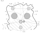
- the sump 14 is arranged at least partly outside a perimeter P defined by a triangle passing through the center of the three masts and through the front mast 16a, in an angular sector delimited by two axes A1, A2 each passing by a center of the tower 8 and forming an angle ⁇ of at most 90°.
- the perimeter considered here is a shape which combines a triangle and a circle, the latter being an axial projection of the front mast 16a on the bottom wall, its center then being placed at a vertex of the triangle.
- the sump 14 is also arranged beyond an arc of a circle C1 centered on the center of the tower 8, said arc of a circle C1 tangent to a rear zone of the front mast 16a of the tower 8. More precisely, the sump 14 is disposed in a zone 26 defined in response to at least three conditions which are that the sump 14 must be disposed outside the perimeter P which combines the triangle and the forward mast projection, that it be disposed in the angular sector previously described and that it is beyond the arc of a circle C1 centered on the tower 8 and which is tangential to the rear zone of the front mast 16a.
- the pumping member 10 is also arranged at least in part outside the perimeter P defined above, in the angular sector delimited by the two axes A1, A2 each passing through the center of tower 8 and forming an angle of at most 90°, and finally beyond the arc of a circle C1 centered on the center of tower 8 and which is tangential to the rear zone of the front mast 16a of tower 8 Indeed, the pumping member 10 is less partially disposed in the sump 14.
- the perimeter P delimited at least in part by the triangle of vertices centered on the masts corresponds to an axial projection of the center of each mast joined by sides of the triangle, this projection being visible in a plane perpendicular to the vertical direction V.
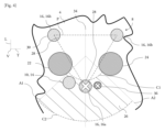
- each of the masts 16 has an inner face 28 oriented towards the other masts 16 and an outer face 30 facing the outside of the tower 8, the distinction between the inner face 28 and the outer face 30 being assessed by example here with regard to the sides which form the triangle represented on the figure 3 and4.
- the location of the sump 14 is distinct from a projection of the front mast 16a on the angular sector, as illustrated in the figure 3 And 4 by a cross on the projection of the front mast 16a in the angular sector.
- the angular sector it is here defined by the two axes A1, A2 passing through the center of the tower 8, that is to say the center of a circle passing through the center of the three masts 16 of the tower 8
- the two axes A1, A2 intersect each other at the center of the tower 8.
- These two axes A1, A2 form an angle of at most 90°, and participate in defining at the least partly transversely the zone 26 in which the sump 14 and the pumping member are arranged.
- each of the axes A1, A2 passes through one of the unloading members 22, 24 of the tower 8.
- each of the axes A1, A2 passes through an outer periphery of the unloading members 22, 24.
- the angle of the angular sector is open on the front mast 16a.
- the front mast 16a is framed transversely by the axes A1, A2 defining the angular sector.
- one of the axes A1, A2 participating in delimiting the angular sector intersects with an axis passing through the center of the tower 8 and through the center of the front mast 16a, forming an angle of between 40° and 50°.
- the angle is 45°.
- each of the axes A1, A2 participating in delimiting the angular sector intersects with an axis passing through the center of the two rear masts 16b, each forming an angle of between 40° and 50°.
- the angular sector comprises two angular sub-sectors which are symmetrical with respect to the axis passing through the center of the tower 8 and the center of the front mast 16a, this perpendicular axis also corresponding to the longitudinal axis of the tank.
- the arc of a circle C1 is tangent to a rear zone of the front mast 16a of the tower 8, that is to say a zone of the front mast 16a which is located inside the triangle which helps to form the perimeter P.
- the arc of a circle C1 passes through the inner face 28 of the front mast 16a.
- the sump 14 can be, for example, arranged at the front of the front mast 16a, or be aligned with respect to the front mast 16a, transversely, and globally in any place of the zone 26.
- the arc of a circle C1 has a minimum radius of 1600mm, 1650mm or 1700mm, this dimension being measured in a plane perpendicular to the vertical direction V between the center of the tower 8 and, here, the inner face 28 of the front mast 16a.
- the zone 26 in which the sump 14 is arranged is longitudinally delimited by the arc of a circle C1 previously described, which is a first arc of a circle C1, and a second arc of a circle C2, the zone 26 being thus extending between the first arc of a circle C1 and the second arc of a circle C2 and between the axes A1 and A2 which border the angular sector according to the invention.
- the first arc of a circle C1 corresponds more precisely to a minimum arc of a circle while the second arc of a circle C2 corresponds to a maximum arc of a circle.
- the second arc of a circle C2 is centered on the center of the tower 8, and has a maximum radius equal to 3400mm, advantageously between 3200mm and 3400mm.
- the second arc of a circle C2 has a radius of 3300mm.
- the invention thus relates to a zone 26 of the bottom wall 4 of the tank 2 in which the sump 14 and the pumping member 10 are arranged.
- This zone 26 is at least delimited transversely by the axes A1, A2 defining the angular sector, longitudinally at least by the first arc of a circle C1 and advantageously by the second arc of a circle C2, while excluding the interior of the perimeter formed by the perimeter P of the tower 8.
- an axis 34 passing through the center of the tower 8 and the center of the front mast 16a passes through the sump 14, the axis 34 being substantially parallel to the direction longitudinal L.
- the sump 14, the front mast 16a and the center of the tower 8 are aligned with each other. It is understood that in this arrangement, the sump 14 is far enough from the tower 8 to limit the stiffening of the bottom wall 4 of the tank 2 that its installation imposes.
- the pumping member 10 is also aligned with the front mast 16a and the center of the tower 8, which facilitates the operations of installation, assembly and/or maintenance of said pumping member 10 in the tank 2 .
- the tower 8 comprises the system 36 for loading liquefied gas from the tank 2, a projection of the loading system 36 on the bottom wall 4 being arranged in the zone 26, a location of the sump 14 in the zone 26 being distinct from the projection of the loading system 36.
- “separate” is meant the fact that the location of the sump 14 and the projection of the loading system 36 do not overlap, that is to say that the sump 14 is not not arranged below the loading system 36.
- the distinct arrangement of the location of the sump 14 and the projection of the loading system 36 makes it possible to avoid projecting liquefied gas directly into the sump 14, and therefore at least partly on the pumping member 10, when loading tank 2 with liquefied gas.
- superimposing the loading system 36 and the sump 14 would complicate the installation and assembly of the tower 8 in the tank 2.
- the angular sector is separated into a first sub-sector and a second sub-sector by the axis 34 passing through the center of the tower 8 and the center of the front mast 16a, the projection of the loading system 36 being arranged in the first sub-sector while the sump 14 is arranged in the second sub-sector.
- the location of the sump 14 and the projection of the loading system 36 transversely surround the front mast 16a.
- a straight line passing through the center of the projection of the loading system 36 and through the center of the front mast 16a also passes through the sump 14.
- This straight line passes more precisely through the sump 14, without however necessarily passing through the center of said sump 14.
- the present invention cannot however be limited to the means and configurations described and illustrated here and it also extends to any equivalent means and configuration as well as to any technically effective combination of such means.
- the description of the location of the sump 14 in the first exemplary embodiment and in the second exemplary embodiment does not limit the invention, these examples being only illustrations of the implementation of the 'invention.
- the invention relates to the fact that the sump 14 is arranged in an area 26 delimited at least by the angular sector defined by the two axes A1, A2, the perimeter P of the tower 8 and optionally the circular arc C1.
Landscapes
- Engineering & Computer Science (AREA)
- Mechanical Engineering (AREA)
- General Engineering & Computer Science (AREA)
- Chemical & Material Sciences (AREA)
- Combustion & Propulsion (AREA)
- Ocean & Marine Engineering (AREA)
- Physics & Mathematics (AREA)
- Thermal Sciences (AREA)
- Filling Or Discharging Of Gas Storage Vessels (AREA)
Abstract
Description
- La présente invention se rapporte au domaine du stockage et/ou de transport d'une cargaison de gaz liquéfié, tels que du gaz naturel liquéfié, de l'ammoniac liquide ou encore du gaz de pétrole liquéfié. Plus particulièrement, l'invention se rapporte à une tour de chargement et de déchargement d'une cuve de stockage de gaz liquéfié.
- Le gaz naturel liquéfié, communément connu sous l'acronyme « GNL », ou encore sous l'acronyme « LNG » pour « Liquefied Naturel Gas », est une source d'énergie importante, composée d'environ 95% de méthane. Plus particulièrement, le GNL est stocké à l'état liquide dans une cuve isolée thermiquement à une température proche de -160°C, le GNL occupant alors 1/600 du volume qu'il occuperait à l'état gazeux, permettant ainsi de faciliter son transport d'un site à un autre.
- Classiquement, la cuve comprend une tour de chargement et de déchargement suspendue à un couvercle qui ferme une ouverture de la cuve. La tour de chargement et de déchargement peut comporter une structure de type tripode, c'est-à-dire comportant trois mât verticaux reliés les uns aux autres par des traverses formant une structure en treillis, ladite tour étant guidée par un support de la cuve émergeant d'une paroi de fond. La tour de chargement et de déchargement comprend alors au moins un conduit de déchargement et un organe de pompage dont la fonction est de décharger la cargaison hors de la cuve, ledit organe de pompage étant relié à un dispositif d'entrainement disposé en dehors de la cuve. Par ailleurs, afin de permettre une aspiration complète de la cargaison, l'élément d'aspiration est disposé au moins en partie dans un puisard formé dans la paroi de fond de la cuve qui permet d'augmenter la quantité de la cargaison extraite par le conduit de déchargement tout en assurant l'immersion de l'élément d'aspiration dans ladite cargaison, préservant ainsi son intégrité.
- Il est alors connu de disposer le conduit de déchargement dans un des mâts de la tour de chargement et de déchargement. Un des inconvénients d'un tel arrangement de la tour de chargement et de déchargement réside alors dans la proximité entre le support guidant la tour et le puisard formé en regard du conduit de déchargement. Une telle proximité limite en effet la propriété de déformation de la paroi de cuve lors du stockage de la cargaison et lors de la mise à froid de la cuve préalablement à son remplissage par le gaz liquéfié, cette propriété de déformation étant nécessaire pour limiter la détérioration de la cuve. Par ailleurs, une telle disposition du conduit de déchargement dans un des mâts de la structure de la tour complexifie son accessibilité pour un opérateur. On comprend ainsi, qu'une telle configuration de la cuve et plus particulièrement de la tour de chargement et de déchargement, augmente les contraintes mécaniques sur ladite cuve, nécessaire au stockage de gaz liquéfié, tout en limitant l'accessibilité du conduit de déchargement.
- La présente invention s'inscrit dans ce contexte en proposant une disposition de l'organe de pompage différente des solutions de positionnement déjà existantes permettant d'une part de faciliter l'accès à l'organe de pompage et au conduit de déchargement et d'autre part de réduire les contraintes mécaniques imposées à la cuve de stockage.
- La présente invention a ainsi pour principal objet une cuve destinée à un ouvrage et configurée pour contenir un gaz liquéfié, comprenant une paroi de fond, une paroi de plafond et plusieurs parois latérales s'étendant entre la paroi de fond et la paroi de plafond, la cuve de stockage comprenant au moins une tour de chargement et/ou de déchargement s'étendant le long d'une direction verticale entre la paroi de fond et la paroi de plafond, la tour comprenant une base et au moins trois mâts solidaires de la base dont deux mâts forment des mâts arrières et le troisième mât forme un mât avant, la tour comprenant au moins un organe de pompage du gaz liquéfié et un puisard s'étendant au travers de la paroi de fond et dans lequel l'organe de pompage est au moins partiellement disposé, caractérisée en ce que le puisard est disposé au moins en partie à l'extérieur d'un périmètre défini par un triangle de sommets centrés sur les mâts et passant par une périphérie du mât avant, le puisard étant disposé dans un secteur angulaire délimité par deux axes passant chacun par un centre de la tour et formant un angle d'au maximum de 90°.
- La tour permet ainsi de pouvoir charger ou décharger du gaz liquéfié dans ou depuis une cuve dans laquelle la tour est installée.
- Le périmètre délimité par le triangle et le mât avant correspond à une projection axiale des trois mâts de la tour sur la paroi de fond de la cuve de stockage, cette projection étant visible dans un plan perpendiculaire à la direction verticale de la tour. Le triangle présente trois sommets qui sont chacun situé au centre de chaque mât, le périmètre englobant une périphérie externe du mât avant.
- Ainsi, on tire avantage de l'emplacement du puisard dans cette zone délimitée par les différentes caractéristiques décrites ci-dessus, cette disposition permettant d'éloigner le puisard et l'organe de pompage de la base de la tour. L'éloignement du puisard réduit la rigidification de la paroi de fond de la cuve, l'éloignement de l'organe de pompage facilitant les actions de montage, d'installation, de maintenance ou autre à réaliser sur ledit organe de pompage.
- Selon une caractéristique optionnelle, l'organe de pompage est configuré pour alimenter en carburant au moins un consommateur de l'ouvrage. Selon une autre solution, l'organe de pompage est configuré pour pomper la cargaison hors de la cuve, notamment en vue de la décharger.
- Selon une caractéristique optionnelle de l'invention, le puisard est disposé au-delà d'un arc de cercle centré sur le centre de la tour, ledit arc de cercle tangentant une zone arrière du mât avant de la tour.
- On entend par ailleurs par « centre de la tour » le centre d'un cercle passant par le centre des trois mâts de la tour. Ce centre est pris comme référence pour l'arc de cercle passant par le mât avant constituant une délimitation d'une zone dans laquelle est disposée le puisard.
- Plus précisément, cette zone dans laquelle est disposé le puisard est définie en réponse à au moins trois conditions qui sont que le puisard doit être disposé en dehors du périmètre, qu'il soit disposé dans le secteur angulaire précédemment décrit et qu'il soit au-delà de l'arc de cercle centré sur la tour et passant par une périphérie arrière du mât avant. Autrement dit, le puisard est dans une zone de la paroi de fond définie d'une part par un secteur angulaire délimité par deux axes passant chacun par un centre de la tour et formant un angle d'au maximum de 90°, le mât avant étant disposé dans le secteur angulaire, la zone étant définie d'autre part par un arc de cercle centré sur le centre de la tour, l'arc de cercle tangentant la zone arrière du mât avant de la tour.
- Selon une caractéristique optionnelle de l'invention, l'angle du secteur angulaire est ouvert sur le mât avant. En d'autres termes, le mât avant est disposé dans le secteur angulaire tout en participant à déterminer le périmètre d'exclusion.
- Selon une caractéristique optionnelle de l'invention, la tour comprend au moins un organe de déchargement disposé entre le mât avant et l'un ou l'autre des mâts arrière. Une projection axiale de cet organe de déchargement, ici une pompe, croise le triangle qui forme une partie du périmètre d'exclusion. On comprend que l'organe de pompage qui est disposé dans le puisard est destiné à aspirer du gaz liquéfié pour alimenter en carburant au moins un consommateur de l'ouvrage ou pour décharger le gaz liquéfié de la cuve de stockage. L'organe de déchargement quant à lui est destiné uniquement au déchargement en gaz liquéfié de la cuve de stockage.
- Selon une autre caractéristique optionnelle de l'invention, l'organe de déchargement est un premier organe de déchargement, la tour comprenant un deuxième organe de déchargement, le premier organe de déchargement étant disposé entre le mât avant et l'un des mâts arrière, le deuxième organe de déchargement étant disposé entre le mât avant et l'autre mât arrière et selon une projection axiale identique à celle du premier organe de déchargement.
- Selon une autre caractéristique optionnelle de l'invention, l'un des axes participant à délimiter le secteur angulaire est sécant avec un axe passant par le centre de la tour et le centre du mât avant en formant un angle compris entre 40° et 50°.
- Selon une autre caractéristique optionnelle de l'invention, l'un des axes participant à délimiter le secteur angulaire est sécant avec un axe passant par le centre de la tour et le centre du mât avant en formant un angle de 45°.
- Selon une autre caractéristique optionnelle de l'invention, l'arc de cercle présente un rayon minimal égal à 1600mm.
- Selon une autre caractéristique optionnelle de l'invention, l'arc de cercle présente un rayon de 1650mm ou 1700mm.
- Selon une autre caractéristique optionnelle de l'invention, l'arc de cercle est un arc de cercle minimal, le puisard étant disposé entre l'arc de cercle minimal et un arc de cercle maximal centré sur le centre de la tour et de rayon au maximum égal à 3400mm.
- Selon une autre caractéristique optionnelle de l'invention, la tour comprend un système de chargement en gaz liquéfié de la cuve, une projection du système de chargement sur la paroi de fond étant disposée dans le secteur angulaire, un emplacement du puisard dans le secteur angulaire étant distinct de la projection du système de chargement. On comprend par « distinct » le fait que l'emplacement du puisard et la projection axiale du système de chargement ne se coupe pas, c'est-à-dire que le puisard n'est pas disposé totalement ou partiellement en-dessous du système de chargement.
- Selon une autre caractéristique optionnelle de l'invention, le secteur angulaire comprend un premier sous-secteur et un deuxième sous-secteur symétriques par rapport à un axe passant par le centre de la tour et le centre du mât avant.
- Selon un aspect, une projection du système de chargement sur la paroi de fond est disposée dans le premier sous-secteur tandis que le puisard est disposé dans le deuxième sous-secteur.
- De manière avantageuse, le puisard et une projection du système de chargement sur la paroi de fond sont disposés dans le même sous-secteur .
- Selon une autre caractéristique optionnelle de l'invention, une droite passant par le centre du système de chargement et le centre du mât avant passe également par le puisard. Cette droite passe plus précisément par le puisard, sans pour autant passer nécessairement par le centre dudit puisard.
- Selon une autre caractéristique optionnelle de l'invention, un axe passant par le centre de la tour et par le centre du mât avant passe par le puisard.
- Selon une autre caractéristique optionnelle de l'invention, au moins la paroi de fond de la cuve de stockage comprend au moins une couche thermiquement isolante et une membrane d'étanchéité portée par la couche thermiquement isolante, la membrane d'étanchéité participant à définir un volume interne de la cuve, la membrane d'étanchéité comprenant plusieurs bandes métalliques présentant des bords relevés et reliées les unes aux autres par leurs bords relevés.
- La présente invention a également pour objet un ouvrage comprenant une cuve de stockage telle que décrite dans le présent document, l'ouvrage étant choisi parmi un navire de transport du gaz liquéfié, une barge, une unité de reliquéfaction, une unité de gazéification, une plateforme gravitaire ou une structure terrestre.
- D'autres caractéristiques, détails et avantages de l'invention ressortiront plus clairement à la lecture de la description qui suit d'une part, et de plusieurs exemples de réalisation donnés à titre indicatif et non limitatif en référence aux dessins schématiques annexés d'autre part, sur lesquels :
- [
Fig. 1 ] est une représentation schématique d'un navire vu de dessus et équipé d'une cuve de stockage d'un gaz liquéfié selon l'invention et comportant une tour de chargement et/ou de déchargement ; - [
Fig. 2 ] est une représentation en perspective de la tour illustrée sur lafigure 1 ; - [
Fig. 3 ] est une coupe schématique d'un premier exemple de positionnement d'un puisard dans une paroi de la cuve illustrée sur lafigure 1 ; - [
Fig. 4 ] est une coupe schématique d'un deuxième exemple de positionnement d'un puisard dans une paroi de la cuve illustrée sur lafigure 1 . - Les caractéristiques, variantes et les différentes formes de réalisation de l'invention peuvent être associées les unes avec les autres, selon diverses combinaisons, dans la mesure où elles ne sont pas incompatibles ou exclusives les unes par rapport aux autres. On pourra notamment imaginer des variantes de l'invention ne comprenant qu'une sélection de caractéristiques décrites par la suite de manière isolée des autres caractéristiques décrites, si cette sélection de caractéristiques est suffisante pour conférer un avantage technique et/ou pour différencier l'invention par rapport à l'état de la technique antérieur.
- Sur les figures, les éléments communs à plusieurs figures conservent la même référence.
- Dans la description détaillée qui va suivre, les dénominations « longitudinale », « transversale » et « verticale » se réfèrent à l'orientation d'une cuve de stockage selon l'invention. Une direction longitudinale correspond à une direction principale d'allongement de la cuve de stockage, cette direction longitudinale étant parallèle à un axe longitudinal L d'un repère L, V, T illustré sur les figures. Une direction verticale correspond à une direction le long de laquelle une tour de chargement et/ou de déchargement s'étend principalement, cette direction verticale étant parallèle à un axe vertical V du repère L, V, T et cet axe vertical V étant perpendiculaire à l'axe longitudinal L. Enfin, une direction transversale correspond à une direction parallèle à un axe transversal T du repère L, V, T, cet axe transversal T étant perpendiculaire à l'axe longitudinal L et l'axe vertical V.
- La
figure 1 illustre un ouvrage 1 correspondant ici à un navire de transport d'un gaz liquéfié. Afin de transporter le gaz liquéfié, le navire comprend au moins une cuve 2 de stockage et/ou de transport du gaz liquéfié comprenant au moins une paroi de fond 4, visible sur lesfigures 2 à 4 , et une paroi de plafond, ici non visibles et opposées l'une à l'autre suivant une direction verticale V de la cuve 2, lesdites parois étant reliées l'une à l'autre par des parois latérales 6. La paroi de fond 4, la paroi de plafond et les parois latérales 6 participent à délimiter un volume de stockage du gaz liquéfié. - La cuve 2 est configurée pour stocker un gaz à l'état liquide, ce gaz pouvant être du gaz naturel liquéfié, de l'ammoniac liquide ou encore du gaz de pétrole liquéfié par exemple. Ces gaz sont à l'état liquide à de basses températures, généralement inférieures à 0°C et pouvant aller jusqu'à -163°C pour le gaz naturel liquide, par exemple.
- Une telle cuve 2 est peut-être installée par exemple sur un ouvrage 1 destiné au transport du gaz liquéfié, tel qu'un navire ou une barge, au traitement du gaz liquéfié, tel qu'une unité de reliquéfaction et/ou une unité de gazéification, ou encore au stockage du gaz liquéfié, tel qu'une structure terrestre ou une plateforme gravitaire.
- Par ailleurs, au moins la paroi de fond 4 comprend au moins une couche thermiquement isolante et une membrane d'étanchéité portée par la couche thermiquement isolante.
- Avantageusement, chacune des parois de la cuve 2 comprend au moins une couche thermiquement isolante et une membrane d'étanchéité.
- Comme visible sur la
figure 1 , les parois de la cuve 2 comprennent au moins un espace primaire participant à délimiter un volume interne de la cuve 2 et un espace secondaire portant l'espace primaire, chacun des espaces comprenant une couche thermiquement isolante et une membrane d'étanchéité. On comprend que les parois de la cuve 2 sont ainsi composées de couches et de membranes superposées les unes au-dessus des autres. - Plus précisément, les parois de la cuve 2 comprennent, depuis l'extérieur de la cuve 2 vers le volume interne de ladite cuve 2, une couche thermiquement isolante secondaire, une membrane d'étanchéité secondaire portée par la couche thermiquement isolante secondaire, une couche thermiquement isolante primaire disposée sur la membrane d'étanchéité secondaire et une membrane d'étanchéité primaire portée par la couche thermiquement isolante primaire, la membrane d'étanchéité primaire participant à délimiter le volume interne de la cuve 2. Les couches thermiquement isolantes sont formées de blocs thermiquement isolant, ou de caissons en panneaux de contreplaqués de bois remplis d'un matériau thermiquement isolant.
- Dans la suite de la description, les caractéristiques décrites en rapport avec le terme « membrane d'étanchéité » peuvent être relatives à la membrane d'étanchéité primaire et/ou à la membrane d'étanchéité secondaire, sauf mention contraire.
- La membrane d'étanchéité quant à elle comprend plusieurs bandes métalliques présentant chacune une face externe en contact de la couche thermiquement isolante primaire et une face interne en regard du volume interne de la cuve 2. Les bandes métalliques présentent de plus un bord replié, les bandes métalliques étant reliées entre elles via leurs bords repliés. Autrement dit, les bords repliés de deux bandes métalliques voisines l'une de l'autre sont rendues solidaires l'un de l'autre, par soudage par exemple, rendant par ce fait les bandes métalliques solidaires l'une de l'autre. La fixation des bandes métalliques les unes aux autres par le biais de leurs bords repliés favorisent une élasticité de la membrane d'étanchéité, notamment lorsque les parois de la cuve 2 subissent des déformations thermiques lors du chargement et/ou du déchargement de la cuve 2 en gaz liquéfié.
- De plus, et tel que visible sur les
figures 1 et2 , la cuve 2 comprend une tour 8 de chargement et/ou de déchargement s'étendant verticalement entre la paroi de fond 4 et la paroi de plafond. La tour 8 est configurée pour charger et/ou décharger le gaz liquéfié dans et/ou depuis la cuve 2, et comprend un organe de pompage 10 apte à aspirer le gaz liquéfié contenu dans la cuve 2. Par exemple, l'organe de pompage 10 est une pompe qui peut récupérer du gaz liquéfié s'écoulant dans le puisard 14 afin par exemple d'alimenter un consommateur d'un navire dans lequel est installée la cuve 2, un tel consommateur étant par exemple un moteur d'un générateur d'électricité. - Plus particulièrement, la paroi de plafond comprend une ouverture dans laquelle est disposé un couvercle 12 constitutif de la cuve 2 de manière à fermer le volume de stockage de la cuve 2 de manière étanche, notamment en prolongeant au niveau de l'ouverture la paroi de plafond. Tel que visible à la
figure 2 , le couvercle 12 est au moins en partie traversé par la tour 8 de sorte à pouvoir charger ou décharger du gaz liquéfié vers ou depuis l'espace de stockage de la cuve 2. - La cuve 2 comprend en outre au moins un puisard 14 dans lequel est logé au moins partiellement l'organe de pompage 10. Le puisard 14 est disposé au travers de la paroi de fond 4 de la cuve 2 et permet ainsi de pouvoir aspirer le gaz liquéfié s'écoulant dans la cuve 2.
- La tour 8, particulièrement visible à la
figure 2 , comprend une structure qui s'étend principalement suivant une direction principale d'extension parallèle à la direction verticale V en présentant une extrémité supérieure et une extrémité inférieure, l'extrémité supérieure étant en regard de la paroi de plafond tandis que l'extrémité inférieure est en regard de la paroi de fond 4. Plus particulièrement, la tour 8 est formée par au moins trois mâts 16, ou autrement appelé structure tripode, et une base 18 disposée avantageusement à son extrémité inférieure rendant solidaire les trois mâts 16 les uns avec les autres. - De manière plus précise, la structure de la tour 8 de chargement comprend les au moins trois mâts 16 solidaires les uns des autres au moyen d'une structure en treillis 20, chacun des trois mâts 16 traversant le couvercle de la cuve 2. On définit alors un mât avant 16a de la tour 8 et deux mâts arrière 16b de la tour 8, définis selon un sens d'avancement du navire, visible à la
figure 1 , dans des conditions normales de navigation, le mât avant 16a étant le mât de la tour 8 le plus en avant dans la cuve 2. - En plus de l'organe de pompage 10, la tour 8 comprend au moins un organe de déchargement 22, 24 du gaz liquéfié présent dans la cuve 2, l'organe de déchargement 22, 24 étant disposé entre le mât avant 16a et l'un ou l'autre des mâts arrière 16b, l'organe de pompage 10 étant configuré pour alimenter en carburant au moins un consommateur de l'ouvrage 1. Par « disposé entre le mât avant 16a et l'un ou l'autre des mâts arrière 16b », on entend le fait qu'une ligne passant par le centre du mât avant 16a et le centre dudit mât arrière 16b passe par l'organe de déchargement 22, 24.
- Dans cette configuration, l'organe de déchargement 22, 24 est destiné uniquement au déchargement en gaz liquéfié de la cuve 2, l'organe de pompage 10 quant à lui, qui est disposé dans le puisard 14, étant pour rappel destiné à aspirer du gaz liquéfié pour soit alimenter en carburant au moins un consommateur de l'ouvrage 1 soit décharger le gaz liquéfié de la cuve 2.
- Tel qu'illustré sur les
figures 3 et4 , la tour 8 comprend un premier organe de déchargement 22 et un deuxième organe de déchargement 24, le premier organe de déchargement 22 étant disposé entre le mât avant 16a et l'un des mâts arrière 16b, le deuxième organe de déchargement 24 étant disposé entre le mât avant 16a et l'autre mât arrière 16b. Les organes de déchargement 22, 24 sont alignés l'un par rapport à l'autre le long d'une direction parallèle à la direction transversale T. - Selon l'invention et comme visible sur la
figure 3 , le puisard 14 est disposé au moins en partie à l'extérieur d'un périmètre P défini par un triangle passant par le centre des trois mâts et par le mât avant 16a, dans un secteur angulaire délimité par deux axes A1, A2 passant chacun par un centre de la tour 8 et formant un angle α d'au maximum de 90°. Le périmètre envisagé ici est une forme qui combine un triangle et un cercle, ce dernier étant une projection axiale du mât avant 16a sur la paroi de fond, son centre étant alors placé en un sommet du triangle. - Le puisard 14 est également disposé au-delà d'un arc de cercle C1 centré sur le centre de la tour 8, ledit arc de cercle C1 tangentant une zone arrière du mât avant 16a de la tour 8. Plus précisément, le puisard 14 est disposé dans une zone 26 définie en réponse à au moins trois conditions qui sont que le puisard 14 doit être disposé en dehors du périmètre P qui combine le triangle et la projection de mât avant, qu'il soit disposé dans le secteur angulaire précédemment décrit et qu'il soit au-delà de l'arc de cercle C1 centré sur la tour 8 et qui tangente la zone arrière du mât avant 16a.
- Selon un aspect de l'invention, l'organe de pompage 10 est également disposé au moins en partie à l'extérieur du périmètre P défini ci-dessus, dans le secteur angulaire délimité par les deux axes A1, A2 passant chacun par le centre de la tour 8 et formant un angle d'au maximum de 90°, et enfin au-delà de l'arc de cercle C1 centré sur le centre de la tour 8 et qui tangente la zone arrière du mât avant 16a de la tour 8. En effet, l'organe de pompage 10 est moins en partie disposé dans le puisard 14.
- Le périmètre P délimité au moins en partie par le triangle de sommets centrés sur les mâts correspond à une projection axiale du centre de chaque mât joint par des côté du triangle, cette projection étant visible dans un plan perpendiculaire à la direction verticale V.
- On note que chacun des mâts 16 présente une face intérieure 28 orientée vers les autres mâts 16 et une face extérieure 30 en regard de l'extérieur de la tour 8, la distinction entre la face intérieure 28 et la face extérieure 30 s'appréciant par exemple ici au regard des côtés qui forment le triangle représentés sur les
figures 3 et4. - Comme le mât avant 16a fait partie du périmètre d'exclusion, on comprend que l'emplacement du puisard 14 est distinct d'une projection du mât avant 16a sur le secteur angulaire, comme cela est illustré sur les
figures 3 et4 par une croix sur la projection du mât avant 16a dans le secteur angulaire. - Quant au secteur angulaire, il est ici défini par les deux axes A1, A2 passant par le centre de la tour 8, c'est-à-dire le centre d'un cercle passant par le centre des trois mâts 16 de la tour 8. Autrement dit, les deux axes A1, A2 sont sécants l'un de l'autre au centre de la tour 8. Ces deux axes A1, A2 forment un angle d'au maximum de 90°, et participent à définir au moins en partie transversalement la zone 26 dans laquelle est disposé le puisard 14 et l'organe de pompage.
- Avantageusement, chacun des axes A1, A2 passe par l'un des organes de déchargement 22, 24 de la tour 8. Par exemple, et comme illustré schématiquement sur les
figures 3 et4 , chacun des axes A1, A2 passe par un pourtour externe des organes de déchargement 22, 24. - De plus, l'angle du secteur angulaire est ouvert sur le mât avant 16a. En d'autres termes, le mât avant 16a est encadré transversalement par les axes A1, A2 définissant le secteur angulaire.
- Comme visible sur la
figure 3 , l'un des axes A1, A2 participant à délimiter le secteur angulaire est sécant avec un axe passant par le centre de la tour 8 et par le centre du mât avant 16a, en formant un angle compris entre 40° et 50°. Avantageusement, l'angle est de 45°. - Encore plus avantageusement, chacun des axes A1, A2 participant à délimiter le secteur angulaire est sécant avec un axe passant par le centre des deux mâts arrière 16b en formant chacun un angle compris entre 40° et 50°.
- Le secteur angulaire comprend deux sous-secteurs angulaires qui sont symétriques par rapport à l'axe passant par le centre de la tour 8 et le centre du mât avant 16a, cet axe perpendiculaire correspondant également à l'axe longitudinal de la cuve.
- Enfin, concernant l'arc de cercle C1, il s'inscrit dans un cercle centré sur le centre de la tour 8, c'est-à-dire le centre du cercle passant par le centre de chacun des mâts 16 de la tour 8, et constitue une limite minimale de la zone 26 dans laquelle est disposée le puisard 14. On comprend que l'emplacement du puisard 14 dans la zone 26 est située au-delà de cet arc de cercle C1, vers l'avant de la cuve 2.
- Comme visible sur les
figures 3 et4 , l'arc de cercle C1 tangente une zone arrière du mât avant 16a de la tour 8, c'est-à-dire une zone du mât avant 16a qui est située à l'intérieure du triangle qui participe à former le périmètre P. Avantageusement, l'arc de cercle C1 passe par la face intérieure 28 du mât avant 16a. On comprend que le puisard 14 peut être, par exemple, disposé à l'avant du mât avant 16a, ou être aligné par rapport au mât avant 16a, transversalement, et globalement en toute endroit de la zone 26. - L'arc de cercle C1 présente un rayon minimal de 1600mm, 1650mm ou 1700mm, cette dimension étant mesurée dans un plan perpendiculaire à la direction verticale V entre le centre de la tour 8 et, ici, la face intérieure 28 du mât avant 16a.
- Selon l'invention, la zone 26 dans laquelle est disposée le puisard 14 est longitudinalement délimitée par l'arc de cercle C1 précédemment décrit, qui est un premier arc de cercle C1, et un deuxième arc de cercle C2, la zone 26 s'étendant ainsi entre le premier arc de cercle C1 et le deuxième arc de cercle C2 et entre les axes A1 et A2 qui bordent le secteur angulaire selon l'invention.
- Le premier arc de cercle C1 correspond plus précisément à un arc de cercle minimal tandis que le deuxième arc de cercle C2 correspond à un arc de cercle maximal. Similairement au premier arc de cercle C1, le deuxième arc de cercle C2 est centré sur le centre de la tour 8, et présente un rayon maximal égal à 3400mm, avantageusement compris entre 3200mm et 3400mm. Avantageusement, le deuxième arc de cercle C2 présente un rayon de 3300mm.
- On comprend de ce qui précède que l'invention porte ainsi sur une zone 26 de la paroi de fond 4 de la cuve 2 dans laquelle est disposée le puisard 14 et l'organe de pompage 10. Cette zone 26 est au moins délimitée transversalement par les axes A1, A2 définissant le secteur angulaire, longitudinalement au moins par le premier arc de cercle C1 et avantageusement par le deuxième arc de cercle C2, tout en excluant l'intérieur du périmètre formée par le périmètre P de la tour 8.
- On va maintenant décrire deux exemples de réalisation de l'invention dans lesquels l'emplacement du puisard 14 dans la zone 26 est différent. Un premier exemple de réalisation de l'invention, en référence à la
figure 3 , sera tout d'abord décrit, puis un deuxième exemple de réalisation de l'invention, en référence à lafigure 4 , sera décrit à la suite de la description du premier exemple de réalisation. - Tel qu'illustré sur la
figure 3 , un axe 34 passant par le centre de la tour 8 et le centre du mât avant 16a passe par le puisard 14, l'axe 34 étant sensiblement parallèle à la direction longitudinale L. Autrement dit, le puisard 14, le mât avant 16a et le centre de la tour 8 sont alignés les uns par rapport aux autres. On comprend que dans cette disposition, le puisard 14 est suffisamment éloigné de la tour 8 pour limiter la rigidification de la paroi de fond 4 de la cuve 2 que sa mise en place impose. De plus, l'organe de pompage 10 est également aligné avec le mât avant 16a et le centre de la tour 8, ce qui favorise les opérations d'installation, de montage et/ou de maintenance dudit organe de pompage 10 dans la cuve 2. - Tel qu'illustré sur la
figure 4 , la tour 8 comprend le système de chargement 36 en gaz liquéfié de la cuve 2, une projection du système de chargement 36 sur la paroi de fond 4 étant disposée dans la zone 26, un emplacement du puisard 14 dans la zone 26 étant distinct de la projection du système de chargement 36. On comprend par « distinct » le fait que l'emplacement du puisard 14 et la projection du système de chargement 36 ne se recoupe pas, c'est-à-dire que le puisard 14 n'est pas disposé en-dessous du système de chargement 36. La disposition distincte de l'emplacement du puisard 14 et la projection du système de chargement 36 permet d'éviter de projeter du gaz liquéfié directement dans le puisard 14, et donc au moins en partie sur l'organe de pompage 10, lors du chargement en gaz liquéfié de la cuve 2. De plus, une superposition du système de chargement 36 et du puisard 14 complexifierait l'installation et le montage de la tour 8 dans la cuve 2. - Comme visible sur la
figure 4 , le secteur angulaire est séparé en un premier sous-secteur et en un deuxième sous-secteur par l'axe 34 passant par le centre de la tour 8 et le centre du mât avant 16a, la projection du système de chargement 36 étant disposée dans le premier sous-secteur tandis que le puisard 14 est disposé dans le deuxième sous-secteur. Autrement dit, l'emplacement du puisard 14 et la projection du système de chargement 36 encadrent transversalement le mât avant 16a. - Avantageusement, une droite passant par le centre de la projection du système de chargement 36 et par le centre du mât avant 16a passe également par le puisard 14. Cette droite passe plus précisément par le puisard 14, sans pour autant passer nécessairement par le centre dudit puisard 14.
- La présente invention ne saurait toutefois se limiter aux moyens et configurations décrits et illustrés ici et elle s'étend également à tout moyen et configuration équivalents ainsi qu'à toute combinaison techniquement opérante de tels moyens. En particulier, la description de l'emplacement du puisard 14 dans le premier exemple de réalisation et dans le deuxième exemple de réalisation n'est pas limitative de l'invention, ces exemples n'étant que des illustrations de la mise en oeuvre de l'invention. Ainsi, et pour rappel, l'invention porte sur le fait que le puisard 14 est disposé dans une zone 26 délimitée au moins par le secteur angulaire défini par les deux axes A1, A2, le périmètre P de la tour 8 et optionnellement l'arc de cercle C1.
Claims (13)
- Cuve (2) destinée à un ouvrage (1) et configurée pour contenir un gaz liquéfié, comprenant une paroi de fond (4), une paroi de plafond et plusieurs parois latérales (6) s'étendant entre la paroi de fond (4) et la paroi de plafond, la cuve (2) comprenant au moins une tour (8) de chargement et/ou de déchargement s'étendant le long d'une direction verticale entre la paroi de fond (4) et la paroi de plafond, la tour (8) comprenant une base (18) et au moins trois mâts (16, 16a, 16b) solidaires de la base (18) dont deux mâts (16) forment des mâts arrière (16b) et le troisième mât (16) forme un mât avant (16a), la tour (8) comprenant au moins un organe de pompage (10) du gaz liquéfié et un puisard (14) s'étendant au travers de la paroi de fond (4) et dans lequel l'organe de pompage (10) est au moins partiellement disposé, caractérisée en ce que le puisard (14) est disposé au moins en partie à l'extérieur d'un périmètre (P) défini par un triangle de sommets centrés sur les mâts (16, 16a, 16b) et passant par une périphérie du mât avant (16a), le puisard (14) étant disposé dans un secteur angulaire délimité par deux axes (A1, A2) passant chacun par un centre de la tour (8) et formant un angle (α) d'au maximum de 90°.
- Cuve (2) selon la revendication 1, dans laquelle le puisard (14) est disposé au-delà d'un arc de cercle (C1) centré sur le centre de la tour (8), ledit arc de cercle (C1) tangentant une zone arrière du mât avant (16a) de la tour (8).
- Cuve (2) selon l'une quelconque des revendications 1 ou 2, dans laquelle la tour (8) comprend au moins un organe de déchargement (22, 24) du gaz liquéfié disposé entre le mât avant (16a) et l'un ou l'autre des mâts arrière (16b).
- Cuve (2) selon l'une quelconque des revendications 1 à 3, dans laquelle l'un des axes (A1, A2) participant à délimiter le secteur angulaire est sécant avec un axe passant par le centre de la tour (8) et une centre du mât avant (16a) en formant un angle compris entre 40° et 50°.
- Cuve (2) selon la revendication 2, dans laquelle l'arc de cercle (C1) présente un rayon minimal égal à 1600mm.
- Cuve (2) selon l'une quelconque des revendications 2 ou 5, dans laquelle l'arc de cercle (C1) est un arc de cercle minimal, le puisard (14) étant disposé entre l'arc de cercle minimal (C1) et un arc de cercle (C2) maximal centré sur le centre de la tour (8) et de rayon maximal égal à 3400mm.
- Cuve (2) selon l'une quelconque des revendications 1 à 6, dans laquelle la tour (8) comprend un système de chargement (36) en gaz liquéfié de la cuve (2), une projection du système de chargement (36) sur la paroi de fond (4) étant disposée dans le secteur angulaire, un emplacement du puisard (14) dans le secteur angulaire étant distinct de la projection du système de chargement (36).
- Cuve (2) selon l'une quelconque des revendications 1 à 7, dans laquelle le secteur angulaire comprend un premier sous-secteur et un deuxième sous-secteur symétriques par rapport à un axe passant par le centre de la tour (8) et le centre du mât avant (16a).
- Cuve (2) selon les revendications 7 et 8, dans laquelle une projection du système de chargement (36) sur la paroi de fond (4) est disposée dans le premier sous-secteur tandis que le puisard (14) est disposé dans le deuxième sous-secteur.
- Cuve (2) selon les revendications 7 et 8, dans laquelle le puisard (14) et une projection du système de chargement (36) sur la paroi de fond (4) sont disposés dans le même sous-secteur.
- Cuve (2) selon l'une quelconque des revendications 1 à 8 ou 10, dans laquelle un axe (34) passant par le centre de la tour (8) et par le centre du mât avant (16a) passe par le puisard (14).
- Cuve (2) selon l'une quelconque des revendications 1 à 11, dans laquelle au moins la paroi de fond (4) de la cuve (2) comprend au moins une couche thermiquement isolante et une membrane d'étanchéité portée par la couche thermiquement isolante, la membrane d'étanchéité participant à définir un volume interne de la cuve (2), la membrane d'étanchéité comprenant plusieurs bandes métalliques présentant des bords relevés et reliées les unes aux autres par leurs bords relevés.
- Ouvrage (1) comprenant une cuve (2) selon l'une quelconque des revendications 1 à 12, l'ouvrage (1) étant choisi parmi un navire de transport du gaz liquéfié, une barge, une unité de reliquéfaction, une unité de gazéification, une plateforme gravitaire ou une structure terrestre.
Applications Claiming Priority (2)
| Application Number | Priority Date | Filing Date | Title |
|---|---|---|---|
| FR2114275A FR3130930B1 (fr) | 2021-12-22 | 2021-12-22 | Tour de chargement et de déchargement d’une cuve de stockage de gaz liquéfié |
| FR2210819A FR3130740B1 (fr) | 2021-12-22 | 2022-10-19 | Cuve de stockage de gaz liquéfié. |
Publications (1)
| Publication Number | Publication Date |
|---|---|
| EP4202285A1 true EP4202285A1 (fr) | 2023-06-28 |
Family
ID=84488177
Family Applications (1)
| Application Number | Title | Priority Date | Filing Date |
|---|---|---|---|
| EP22214632.6A Pending EP4202285A1 (fr) | 2021-12-22 | 2022-12-19 | Cuve de stockage de gaz liquéfié |
Country Status (5)
| Country | Link |
|---|---|
| EP (1) | EP4202285A1 (fr) |
| JP (1) | JP2023093408A (fr) |
| KR (1) | KR20230095853A (fr) |
| CN (1) | CN116428503A (fr) |
| TW (1) | TW202326022A (fr) |
Cited By (1)
| Publication number | Priority date | Publication date | Assignee | Title |
|---|---|---|---|---|
| CN117053494A (zh) * | 2023-08-30 | 2023-11-14 | 中船动力(集团)有限公司 | 一种氨气再液化系统及方法 |
Citations (3)
| Publication number | Priority date | Publication date | Assignee | Title |
|---|---|---|---|---|
| WO2016001142A1 (fr) * | 2014-07-04 | 2016-01-07 | Gaztransport Et Technigaz | Cuve etanche et isolante disposee dans une double coque flottante |
| KR20160119343A (ko) * | 2015-04-03 | 2016-10-13 | 삼성중공업 주식회사 | 액화가스 저장탱크 및 액화가스 배출방법 |
| WO2019211550A1 (fr) * | 2018-05-02 | 2019-11-07 | Gaztransport Et Technigaz | Cuve etanche et thermiquement isolante equipee d'une tour de chargement/dechargement |
-
2022
- 2022-12-19 EP EP22214632.6A patent/EP4202285A1/fr active Pending
- 2022-12-21 JP JP2022204808A patent/JP2023093408A/ja active Pending
- 2022-12-21 KR KR1020220180216A patent/KR20230095853A/ko active Pending
- 2022-12-22 TW TW111149448A patent/TW202326022A/zh unknown
- 2022-12-22 CN CN202211660698.0A patent/CN116428503A/zh active Pending
Patent Citations (3)
| Publication number | Priority date | Publication date | Assignee | Title |
|---|---|---|---|---|
| WO2016001142A1 (fr) * | 2014-07-04 | 2016-01-07 | Gaztransport Et Technigaz | Cuve etanche et isolante disposee dans une double coque flottante |
| KR20160119343A (ko) * | 2015-04-03 | 2016-10-13 | 삼성중공업 주식회사 | 액화가스 저장탱크 및 액화가스 배출방법 |
| WO2019211550A1 (fr) * | 2018-05-02 | 2019-11-07 | Gaztransport Et Technigaz | Cuve etanche et thermiquement isolante equipee d'une tour de chargement/dechargement |
Cited By (1)
| Publication number | Priority date | Publication date | Assignee | Title |
|---|---|---|---|---|
| CN117053494A (zh) * | 2023-08-30 | 2023-11-14 | 中船动力(集团)有限公司 | 一种氨气再液化系统及方法 |
Also Published As
| Publication number | Publication date |
|---|---|
| KR20230095853A (ko) | 2023-06-29 |
| CN116428503A (zh) | 2023-07-14 |
| JP2023093408A (ja) | 2023-07-04 |
| TW202326022A (zh) | 2023-07-01 |
Similar Documents
| Publication | Publication Date | Title |
|---|---|---|
| FR3130740A1 (fr) | Cuve de stockage de gaz liquéfié. | |
| EP3250849B1 (fr) | Installation de stockage et de transport d'un fluide cryogénique embarquée sur un navire | |
| EP3749889A1 (fr) | Installation pour le stockage et le transport d'un gaz liquefie | |
| EP3948060B1 (fr) | Cuve étanche et thermiquement isolante | |
| FR3094071A1 (fr) | Cuve étanche et thermiquement isolante | |
| FR3078136A1 (fr) | Paroi de cuve etanche comprenant une membrane d'etancheite comportant une zone renforcee | |
| EP4357661A1 (fr) | Tour de chargement et/ou de déchargement destinée à équiper une cuve de stockage en gaz liquéfié | |
| FR3078135A1 (fr) | Installation de stockage et de transport d'un fluide cryogenique embarquee sur un navire | |
| EP4013989B1 (fr) | Cuve étanche et thermiquement isolante | |
| EP4202285A1 (fr) | Cuve de stockage de gaz liquéfié | |
| EP3824216A1 (fr) | Installation de stockage de fluide | |
| WO2021228751A1 (fr) | Dôme liquide d'une cuve de stockage pour gaz liquéfié comportant une ouverture munie d'une trappe additionnelle | |
| FR3106193A1 (fr) | Installation de stockage pour gaz liquéfié | |
| EP4083494A1 (fr) | Installation de stockage pour gaz liquefie | |
| WO2022253615A1 (fr) | Installation de stockage d'un gaz liquéfié | |
| EP3645933A1 (fr) | Membrane etanche et procede d'assemblage d'une membrane etanche | |
| FR3077116A1 (fr) | Cuve etanche et thermiquement isolante | |
| WO2021144531A1 (fr) | Double trappe d'accès pour une cuve de transport de gaz liquéfié | |
| EP4031798A1 (fr) | Cuve etanche et thermiquement isolante | |
| EP3678928B1 (fr) | Ouvrage flottant comprenant une cuve apte a contenir du gaz combustible liquéfié | |
| FR3093786A1 (fr) | Paroi de cuve comprenant une isolation améliorée autour d’une traversée | |
| WO2023118716A1 (fr) | Cuve comprenant une membrane étanche présentant des traversées | |
| FR3130931A1 (fr) | Installation de stockage d’un gaz liquéfié comportant une cuve et une structure de dôme | |
| WO2025045663A1 (fr) | Cuve étanche et thermiquement isolante | |
| FR3089594A1 (fr) | Support de fixation d’un moteur sur un couvercle d’une tour de chargement et/ou de déchargement d’une cuve d’un navire |
Legal Events
| Date | Code | Title | Description |
|---|---|---|---|
| PUAI | Public reference made under article 153(3) epc to a published international application that has entered the european phase |
Free format text: ORIGINAL CODE: 0009012 |
|
| STAA | Information on the status of an ep patent application or granted ep patent |
Free format text: STATUS: THE APPLICATION HAS BEEN PUBLISHED |
|
| AK | Designated contracting states |
Kind code of ref document: A1 Designated state(s): AL AT BE BG CH CY CZ DE DK EE ES FI FR GB GR HR HU IE IS IT LI LT LU LV MC ME MK MT NL NO PL PT RO RS SE SI SK SM TR |
|
| STAA | Information on the status of an ep patent application or granted ep patent |
Free format text: STATUS: REQUEST FOR EXAMINATION WAS MADE |
|
| 17P | Request for examination filed |
Effective date: 20231208 |
|
| RBV | Designated contracting states (corrected) |
Designated state(s): AL AT BE BG CH CY CZ DE DK EE ES FI FR GB GR HR HU IE IS IT LI LT LU LV MC ME MK MT NL NO PL PT RO RS SE SI SK SM TR |
|
| STAA | Information on the status of an ep patent application or granted ep patent |
Free format text: STATUS: EXAMINATION IS IN PROGRESS |
|
| 17Q | First examination report despatched |
Effective date: 20250711 |