EP4201683B1 - Flüssigkeitsausstossvorrichtung, flüssigkeitsausstossverfahren und trägermedium - Google Patents
Flüssigkeitsausstossvorrichtung, flüssigkeitsausstossverfahren und trägermedium Download PDFInfo
- Publication number
- EP4201683B1 EP4201683B1 EP22209901.2A EP22209901A EP4201683B1 EP 4201683 B1 EP4201683 B1 EP 4201683B1 EP 22209901 A EP22209901 A EP 22209901A EP 4201683 B1 EP4201683 B1 EP 4201683B1
- Authority
- EP
- European Patent Office
- Prior art keywords
- ink
- liquid
- head
- application surface
- application
- Prior art date
- Legal status (The legal status is an assumption and is not a legal conclusion. Google has not performed a legal analysis and makes no representation as to the accuracy of the status listed.)
- Active
Links
Images











Classifications
-
- B—PERFORMING OPERATIONS; TRANSPORTING
- B41—PRINTING; LINING MACHINES; TYPEWRITERS; STAMPS
- B41J—TYPEWRITERS; SELECTIVE PRINTING MECHANISMS, i.e. MECHANISMS PRINTING OTHERWISE THAN FROM A FORME; CORRECTION OF TYPOGRAPHICAL ERRORS
- B41J2/00—Typewriters or selective printing mechanisms characterised by the printing or marking process for which they are designed
- B41J2/005—Typewriters or selective printing mechanisms characterised by the printing or marking process for which they are designed characterised by bringing liquid or particles selectively into contact with a printing material
- B41J2/01—Ink jet
- B41J2/205—Ink jet for printing a discrete number of tones
- B41J2/2054—Ink jet for printing a discrete number of tones by the variation of dot disposition or characteristics, e.g. dot number density, dot shape
-
- B—PERFORMING OPERATIONS; TRANSPORTING
- B41—PRINTING; LINING MACHINES; TYPEWRITERS; STAMPS
- B41J—TYPEWRITERS; SELECTIVE PRINTING MECHANISMS, i.e. MECHANISMS PRINTING OTHERWISE THAN FROM A FORME; CORRECTION OF TYPOGRAPHICAL ERRORS
- B41J2/00—Typewriters or selective printing mechanisms characterised by the printing or marking process for which they are designed
- B41J2/005—Typewriters or selective printing mechanisms characterised by the printing or marking process for which they are designed characterised by bringing liquid or particles selectively into contact with a printing material
- B41J2/01—Ink jet
- B41J2/015—Ink jet characterised by the jet generation process
- B41J2/04—Ink jet characterised by the jet generation process generating single droplets or particles on demand
- B41J2/045—Ink jet characterised by the jet generation process generating single droplets or particles on demand by pressure, e.g. electromechanical transducers
- B41J2/04501—Control methods or devices therefor, e.g. driver circuits, control circuits
- B41J2/04541—Specific driving circuit
-
- B—PERFORMING OPERATIONS; TRANSPORTING
- B41—PRINTING; LINING MACHINES; TYPEWRITERS; STAMPS
- B41J—TYPEWRITERS; SELECTIVE PRINTING MECHANISMS, i.e. MECHANISMS PRINTING OTHERWISE THAN FROM A FORME; CORRECTION OF TYPOGRAPHICAL ERRORS
- B41J2/00—Typewriters or selective printing mechanisms characterised by the printing or marking process for which they are designed
- B41J2/005—Typewriters or selective printing mechanisms characterised by the printing or marking process for which they are designed characterised by bringing liquid or particles selectively into contact with a printing material
- B41J2/01—Ink jet
-
- B—PERFORMING OPERATIONS; TRANSPORTING
- B05—SPRAYING OR ATOMISING IN GENERAL; APPLYING FLUENT MATERIALS TO SURFACES, IN GENERAL
- B05B—SPRAYING APPARATUS; ATOMISING APPARATUS; NOZZLES
- B05B13/00—Machines or plants for applying liquids or other fluent materials to surfaces of objects or other work by spraying, not covered by groups B05B1/00 - B05B11/00
- B05B13/002—Machines or plants for applying coating liquids or other fluent materials by inkjet
-
- B—PERFORMING OPERATIONS; TRANSPORTING
- B05—SPRAYING OR ATOMISING IN GENERAL; APPLYING FLUENT MATERIALS TO SURFACES, IN GENERAL
- B05B—SPRAYING APPARATUS; ATOMISING APPARATUS; NOZZLES
- B05B13/00—Machines or plants for applying liquids or other fluent materials to surfaces of objects or other work by spraying, not covered by groups B05B1/00 - B05B11/00
- B05B13/02—Means for supporting work; Arrangement or mounting of spray heads; Adaptation or arrangement of means for feeding work
- B05B13/04—Means for supporting work; Arrangement or mounting of spray heads; Adaptation or arrangement of means for feeding work the spray heads being moved during spraying operation
- B05B13/0431—Means for supporting work; Arrangement or mounting of spray heads; Adaptation or arrangement of means for feeding work the spray heads being moved during spraying operation with spray heads moved by robots or articulated arms, e.g. for applying liquid or other fluent material to three-dimensional [3D] surfaces
-
- B—PERFORMING OPERATIONS; TRANSPORTING
- B41—PRINTING; LINING MACHINES; TYPEWRITERS; STAMPS
- B41J—TYPEWRITERS; SELECTIVE PRINTING MECHANISMS, i.e. MECHANISMS PRINTING OTHERWISE THAN FROM A FORME; CORRECTION OF TYPOGRAPHICAL ERRORS
- B41J2/00—Typewriters or selective printing mechanisms characterised by the printing or marking process for which they are designed
- B41J2/005—Typewriters or selective printing mechanisms characterised by the printing or marking process for which they are designed characterised by bringing liquid or particles selectively into contact with a printing material
- B41J2/01—Ink jet
- B41J2/015—Ink jet characterised by the jet generation process
- B41J2/04—Ink jet characterised by the jet generation process generating single droplets or particles on demand
- B41J2/045—Ink jet characterised by the jet generation process generating single droplets or particles on demand by pressure, e.g. electromechanical transducers
- B41J2/04501—Control methods or devices therefor, e.g. driver circuits, control circuits
- B41J2/04556—Control methods or devices therefor, e.g. driver circuits, control circuits detecting distance to paper
-
- B—PERFORMING OPERATIONS; TRANSPORTING
- B41—PRINTING; LINING MACHINES; TYPEWRITERS; STAMPS
- B41J—TYPEWRITERS; SELECTIVE PRINTING MECHANISMS, i.e. MECHANISMS PRINTING OTHERWISE THAN FROM A FORME; CORRECTION OF TYPOGRAPHICAL ERRORS
- B41J2/00—Typewriters or selective printing mechanisms characterised by the printing or marking process for which they are designed
- B41J2/005—Typewriters or selective printing mechanisms characterised by the printing or marking process for which they are designed characterised by bringing liquid or particles selectively into contact with a printing material
- B41J2/01—Ink jet
- B41J2/015—Ink jet characterised by the jet generation process
- B41J2/04—Ink jet characterised by the jet generation process generating single droplets or particles on demand
- B41J2/045—Ink jet characterised by the jet generation process generating single droplets or particles on demand by pressure, e.g. electromechanical transducers
- B41J2/04501—Control methods or devices therefor, e.g. driver circuits, control circuits
- B41J2/04581—Control methods or devices therefor, e.g. driver circuits, control circuits controlling heads based on piezoelectric elements
-
- B—PERFORMING OPERATIONS; TRANSPORTING
- B41—PRINTING; LINING MACHINES; TYPEWRITERS; STAMPS
- B41J—TYPEWRITERS; SELECTIVE PRINTING MECHANISMS, i.e. MECHANISMS PRINTING OTHERWISE THAN FROM A FORME; CORRECTION OF TYPOGRAPHICAL ERRORS
- B41J2/00—Typewriters or selective printing mechanisms characterised by the printing or marking process for which they are designed
- B41J2/005—Typewriters or selective printing mechanisms characterised by the printing or marking process for which they are designed characterised by bringing liquid or particles selectively into contact with a printing material
- B41J2/01—Ink jet
- B41J2/21—Ink jet for multi-colour printing
- B41J2/2121—Ink jet for multi-colour printing characterised by dot size, e.g. combinations of printed dots of different diameter
-
- B—PERFORMING OPERATIONS; TRANSPORTING
- B41—PRINTING; LINING MACHINES; TYPEWRITERS; STAMPS
- B41J—TYPEWRITERS; SELECTIVE PRINTING MECHANISMS, i.e. MECHANISMS PRINTING OTHERWISE THAN FROM A FORME; CORRECTION OF TYPOGRAPHICAL ERRORS
- B41J2/00—Typewriters or selective printing mechanisms characterised by the printing or marking process for which they are designed
- B41J2/005—Typewriters or selective printing mechanisms characterised by the printing or marking process for which they are designed characterised by bringing liquid or particles selectively into contact with a printing material
- B41J2/01—Ink jet
- B41J2/21—Ink jet for multi-colour printing
- B41J2/2132—Print quality control characterised by dot disposition, e.g. for reducing white stripes or banding
-
- B—PERFORMING OPERATIONS; TRANSPORTING
- B41—PRINTING; LINING MACHINES; TYPEWRITERS; STAMPS
- B41J—TYPEWRITERS; SELECTIVE PRINTING MECHANISMS, i.e. MECHANISMS PRINTING OTHERWISE THAN FROM A FORME; CORRECTION OF TYPOGRAPHICAL ERRORS
- B41J29/00—Details of, or accessories for, typewriters or selective printing mechanisms not otherwise provided for
- B41J29/38—Drives, motors, controls or automatic cut-off devices for the entire printing mechanism
- B41J29/393—Devices for controlling or analysing the entire machine ; Controlling or analysing mechanical parameters involving printing of test patterns
-
- B—PERFORMING OPERATIONS; TRANSPORTING
- B41—PRINTING; LINING MACHINES; TYPEWRITERS; STAMPS
- B41J—TYPEWRITERS; SELECTIVE PRINTING MECHANISMS, i.e. MECHANISMS PRINTING OTHERWISE THAN FROM A FORME; CORRECTION OF TYPOGRAPHICAL ERRORS
- B41J3/00—Typewriters or selective printing or marking mechanisms characterised by the purpose for which they are constructed
- B41J3/407—Typewriters or selective printing or marking mechanisms characterised by the purpose for which they are constructed for marking on special material
- B41J3/4073—Printing on three-dimensional objects not being in sheet or web form, e.g. spherical or cubic objects
-
- B—PERFORMING OPERATIONS; TRANSPORTING
- B05—SPRAYING OR ATOMISING IN GENERAL; APPLYING FLUENT MATERIALS TO SURFACES, IN GENERAL
- B05B—SPRAYING APPARATUS; ATOMISING APPARATUS; NOZZLES
- B05B12/00—Arrangements for controlling delivery; Arrangements for controlling the spray area
- B05B12/08—Arrangements for controlling delivery; Arrangements for controlling the spray area responsive to condition of liquid or other fluent material to be discharged, of ambient medium or of target ; responsive to condition of spray devices or of supply means, e.g. pipes, pumps or their drive means
- B05B12/12—Arrangements for controlling delivery; Arrangements for controlling the spray area responsive to condition of liquid or other fluent material to be discharged, of ambient medium or of target ; responsive to condition of spray devices or of supply means, e.g. pipes, pumps or their drive means responsive to conditions of ambient medium or target, e.g. humidity, temperature position or movement of the target relative to the spray apparatus
- B05B12/122—Arrangements for controlling delivery; Arrangements for controlling the spray area responsive to condition of liquid or other fluent material to be discharged, of ambient medium or of target ; responsive to condition of spray devices or of supply means, e.g. pipes, pumps or their drive means responsive to conditions of ambient medium or target, e.g. humidity, temperature position or movement of the target relative to the spray apparatus responsive to presence or shape of target
-
- B—PERFORMING OPERATIONS; TRANSPORTING
- B41—PRINTING; LINING MACHINES; TYPEWRITERS; STAMPS
- B41J—TYPEWRITERS; SELECTIVE PRINTING MECHANISMS, i.e. MECHANISMS PRINTING OTHERWISE THAN FROM A FORME; CORRECTION OF TYPOGRAPHICAL ERRORS
- B41J2202/00—Embodiments of or processes related to ink-jet or thermal heads
- B41J2202/01—Embodiments of or processes related to ink-jet heads
- B41J2202/05—Heads having a valve
Definitions
- the present invention relates to a liquid discharge apparatus, a liquid discharge method, and a carrier medium storing program code as per the appended claims.
- FIGS. 1 and 2 are views illustrating an overall configuration of the liquid discharge apparatus 1000.
- FIG. 1 is a side view and
- FIG. 2 is a front view.
- a Z-axis rail 103 holds the carriage 1 so that the carriage 1 can move in the Z-direction.
- the X-axis rail 101 holds the Z-axis rail 103 such that the Z-axis rail 103 holding the carriage 1 is movable in the X-direction.
- the Y-axis rail 102 holds the X-axis rail 101 such that the X-axis rail 101 is movable in the Y-direction.
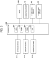
- the controller 500 is configured to control an operation of ink discharge to the application surface 100a by the liquid discharge apparatus 1000.
- the controller 500 is configured by a processor or an electric circuit mounted on an electric board.
- the controller 500 is electrically connected to at least each driver that drives the mover 110 and the head 300 in a wired or wireless manner.
- the electric board on which the controller 500 is mounted is arranged in any position, and the electric board may be arranged remotely with respect to the head 300.
- the liquid discharge apparatus 1000 discharges ink from the head 300 toward the application surface 100a while moving the carriage 1 in each of the X-direction, the Y-direction, and the Z-direction to apply the ink to the application surface 100a.
- the liquid discharge apparatus 1000 does not perform relative movement between the head 300 and the application surface 100a in the Z-direction during an ink application operation.
- the liquid discharge apparatus 1000 performs relative movement between the head 300 and the application surface 100a in the Z-direction according to the shape of the application surface 100a during the ink application operation.
- the CPU 501 uses a RAM 503 as a work area and executes a program stored in the ROM 502 to control the overall operation of the controller 500.
- the ROM 502 is a non-volatile memory that stores a program for executing control such as a recording operation to the CPU 501 and stores other fixed data.
- the display device 512 and the operation panel 513 may be integrated into a single screen such as a touch screen.
- the X-direction driver 72 drives the carriage 1 in the X-direction based on instructions from the controller 500.
- the Y-direction driver 82 drives the carriage 1 in the Y-direction based on instructions from the controller 500.
- the Z-direction driver 92 drives the carriage 1 in the Z-direction based on instructions from the controller 500.
- the controller 500 controls the operations of the X-direction driver 72 and the Y-direction driver 82 to control the movement of the carriage 1, in which the head 300 is included, in the X-direction and the Y-direction.
- the controller 500 controls the operation of the Z-direction driver 92 to control the movement of the head 300 in the Z-direction with respect to the carriage 1. Further, the controller 500 controls discharge of ink from the head 300.
- FIG. 4 is a diagram illustrating an example of the configuration of a supply unit 200 of the liquid discharge apparatus 1000.
- the supply unit 200 supplies ink to the head 300.
- the head 300 includes a head 300Y that discharges yellow (Y) ink, a head 300M that discharges magenta (M) ink, a head 300C that discharges (C) ink, and a head 300K that discharges black (K) ink.
- Y yellow
- M magenta
- C C
- K black
- the heads 300Y, 300M, 300C, and 300K are collectively referred to as the heads 300 in the description below.
- the heads 300 may further include another head, such as a head 300Q that discharges overcoating ink and a head 300P that discharges primer ink or white ink.
- the supply unit 200 supplies ink of each color to the head 300 of each color.
- the ink tank 330 is connected to a compressor 230 through a pipe 331 including an air regulator 332, and the compressor 230 supplies pressurized air. Accordingly, the pressurized ink 325 of each color is supplied to the ink inlet of each head 300, and the liquid discharge apparatus 1000 discharges the ink 325 from each nozzle of the head 300.
- the head 300 includes a plurality of discharge modules 310 arranged in one or a plurality of rows in a housing 10.
- controller 500 may be implemented by any other element such as the head 300 than the controller 500.
- controller 500 may be implemented by the controller 500 and any other element than the controller 500 in a distributed manner.
- the acquisition unit 51 inputs shape information Sd of the application surface 100a from an external device such as a host PC and acquires the shape information Sd.
- the shape information Sd is three-dimensional information representing the shape of the application surface 100a.
- the acquisition unit 51 may read the shape information Sd stored in advance in the storage device 511 to acquire the shape information Sd.
- the liquid discharge apparatus 1000 may include a detection unit to detect the shape of the application surface 100a, and the acquisition unit 51 may receive, from the detection unit, the shape information Sd of the application surface 100a detected by the detection unit to acquire the shape information Sd.
- the acquisition unit 51 outputs the acquired shape information Sd to the ink amount determination unit 52.
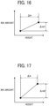
- the ink amount determination unit 52 refers to a table 520 stored in the storage device 511 and determines the ink amount m based on the shape information Sd and the vertical height h of the application position P at which ink discharged from the head 300 is applied on the application surface 100a.
- the table 520 is a table indicating a relation between a predetermined height h and a predetermined ink amount m.
- the ink amount determination unit 52 outputs information of the ink amount m for each application position P to the discharge control unit 53.
- the discharge control unit 53 causes the head 300 to discharge the ink amount m of the ink 325, determined by the ink amount determination unit 52.
- the discharge control unit 53 temporarily stores information of the ink amount m for each application position P input from the ink amount determination unit 52 in the RAM 503 and controls the ink amount m to be discharged from the head 300 according to the application position P that changes the position due to the relative movement of the head 300 by the mover 110.
- the movement control unit 54 controls the relative movement by the mover 110.
- the movement control unit 54 controls the X-direction driver 72, the Y-direction driver 82, and the Z-direction driver 92 to control the relative movement by the mover 110.
- the movement control unit 54 controls the discharge of the ink 325 by the head 300 and the relative movement by the mover 110 so that the ink 325 discharged from the head 300 by a plurality of relative movements by the mover 110 is applied to the application surface 100a.
- FIG. 8 is a flowchart of an operation of the liquid discharge apparatus 1000.
- FIG. 8 illustrates an operation of an ink application to the application surface 100a by the liquid discharge apparatus 1000.
- the liquid discharge apparatus 1000 starts the operation illustrated in FIG. 8 , for example, when the liquid discharge apparatus 1000 receives an instruction of the ink application, input by a user through the operation panel 513.
- step S84 when the controller 500 determines that the operation of the ink application to the application surface 100a is to be ended (YES in step S84), the liquid discharge apparatus 1000 ends the operation of the ink application.
- step S84 when the controller 500 determines that the operation of the ink application to the application surface 100a is not to be ended (NO in step S84), the liquid discharge apparatus 1000 processes the operations of step S83 and step 84 again.
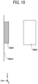
- FIGS. 9 to 11 are diagrams illustrating ink application according to a control sample.
- FIG. 9 is a diagram illustrating ink discharge.
- FIG. 10 is a diagram illustrating ink immediately after the ink is applied to an application surface by the ink discharge illustrated in FIG. 9 .
- FIG. 11 is a diagram illustrating a state after the ink has dripped as time elapses from the state illustrated in FIG. 10 .
- the ink dripping means that ink applied to an application surface drips from a high position to a low position on the application surface due to the action of gravity.
- a head 300X according to the control sample discharges ink 325X to an application surface 100aX.
- the head 300X discharges three ink droplets formed with the ink 325X.
- the volumes of the three ink droplets are substantially equal.
- the ink 325X discharged from the head 300X forms an ink film 326X on the application surface 100aX immediately after the ink 325X is applied to the application surface 100aX. Since the ink 325X is not dried and has fluidity immediately after the ink 325X is applied to the application surface 100aX, the ink dripping occurs due to the action of gravity, and the ink 325X moves from a high position to a low position on the application surface 100aX. As drying progresses with a lapse of time, the amount of movement of the ink 325X from the high position to the low position on the application surface 100aX becomes smaller, and eventually stops and adheres to the application surface 100aX.
- an ink film 327X having a film thickness that increases toward the lower side is formed on the application surface 100aX.
- the thickness of the ink film 327X formed on the application surface 100a is non-uniform.
- the liquid discharge apparatus 1000 increases the ink amount m of the ink 325 to be discharged from the head 300 as the height of the application position P in the vertical direction on the application surface 100a is higher.
- Application positions P1, P2, and P3 represent three application positions P having different heights in the vertical direction.
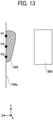
- the ink 325 discharged from the head 300 forms an ink film 326 on the application surface 100a immediately after the ink 325 is applied to the application surface 100a.
- the ink film 326 is the thickest at the application position P1 and becomes thinner in the order of the application position P2 and the application position P3 in accordance with the volumes of the ink droplets applied to the application positions P1, P2, and P3.
- the ink film 326 immediately after the ink 325 is applied to the application surface 100a, the ink film 326 has a non-uniform thickness that is thicker toward the upper side (+Y-direction side).
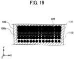
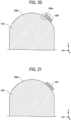
- the ink 325 is applied to form a first region 111 and a second region 112 on the application surface 100b.
- Large droplets 325a are applied to form the first region 111 on the application surface 100b, and small droplets 325c are applied to form the second region 112 on the application surface 100b.
- the first region 111 is located at a position higher than the second region 112 in the vertical direction.
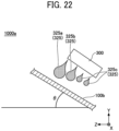
- the interval determination unit 55 determines the interval d between the adjacent inks 325 which are discharged from the head 300 and are applied to the application surface 100b, based on the shape information Sd input from the acquisition unit 51. In the present embodiment, the interval determination unit 55 sets the interval d between the adjacent inks 325 applied to the application surface 100b to be narrower as the height h of the application position P along the vertical direction is higher. In addition, as the inclination ⁇ of the application surface 100b at the application position P increases, the interval determination unit 55 determines the interval d so that the change ⁇ d corresponding to the predetermined height difference of the interval d between the adjacent inks 325 applied to the application surface 100b increases.
- the interval determination unit 55 calculates, based on the shape information Sd, the vertical height h of the application position P at which the ink 325 discharged from the head 300 is applied on the application surface 100b and the inclination ⁇ of the application surface 100b with respect to the horizontal direction at the application position P, to acquire the height h and the inclination ⁇ .
- the interval determination unit 55 refers to a table 520b stored in the storage device 511 based on the acquired height h and inclination ⁇ and determines the interval d.
- the table 520b is a table indicating the relation between the predetermined height h, the inclination ⁇ , and the interval d.
- the interval determination unit 55 can output information of the interval d for each application position P to the discharge control unit 53.
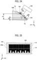
- FIG. 24 is a diagram illustrating an example of the ink discharge by the liquid discharge apparatus 1000b.
- FIG. 25 is a diagram illustrating an example of the ink 325 applied to the application surface 100b by the ink discharge illustrated in FIG. 24 .
- the height h4 of the application position P4 is higher than the height h6 of the application position P6.
- the inclination ⁇ of the application surface 100b at the application position P6 is larger than the inclination ⁇ of the application surface 100b at the application position P4.
- the liquid discharge apparatus 1000b sets an interval d4 between the adjacent inks 325 applied to the application surface 100b at the application position P4 to be narrower than an interval d6 between the adjacent inks 325 applied to the application surface 100b at the application position P6.
- the liquid discharge apparatus 1000b controls so that the change ⁇ d corresponding to the height difference ⁇ h of the interval d between the adjacent inks 325 applied to the application surface 100b is larger as the inclination ⁇ of the application surface 100b at the application position P is larger.
- the interval d between the adjacent inks 325 in the application position P4 is indicated by the interval d4.
- the interval d between the adjacent inks 325 in the application position P6 is indicate by the interval d6.
- the interval d4 is narrower than the interval d6. Since the inclination ⁇ at the application position P4 is smaller than the inclination ⁇ at the application position P6, the difference between the interval d4 at the application position P4 and the interval d6 at the application position P6 is smaller than the difference of the interval d based on the difference between the height h4 and the height h6.
- the ink 325 is applied to form a third region 113 and a fourth region 114 on the application surface 100b.
- the third region 113 is located at a position higher than the fourth region 114 in the vertical direction. Comparing the interval d between the adjacent inks 325, the interval d4 in the third region 113 is narrower than the interval d6 in the fourth region 114. Note that the volumes of ink droplets applied to the third region 113 and the fourth region 114 are substantially equal.
- the ink amount m in the third region 113 becomes larger than the ink amount m in the fourth region 114.
- the controller 500b sets the interval d between the adjacent inks 325 applied to the application surface 100b to be narrower as the height h of the application position P along the vertical direction is higher.
- the controller 500b controls so that the change ⁇ d corresponding to the height difference ⁇ h of the interval d between the adjacent inks 325 applied to the application surface 100b increases as the inclination ⁇ of the application surface 100b at the application position P is larger.
- the ink film formed on the application surface 100b with the ink 325 discharged from the head 300 has a larger thickness as the height h of the application position P is higher.
- the ink 325 having fluidity flows from an upper portion having a large film thickness to a lower portion having a small film thickness due to ink dripping by the action of gravity.
- the ink amount at each application position P along the vertical direction is substantially equalized, and thus an ink film having a substantially uniform film thickness is obtained. Due to the above-described configuration, in the present embodiment, the liquid discharge apparatus 1000b which is excellent in the application qualities of the ink 325 to the application surface 100b can be provided.
- the liquid discharge apparatus 1000b may control the interval d based on only the height h of the application position P.
- the liquid discharge apparatus 1000b may control the ink amount m and the interval d based on only the height h of the application position P.
- the liquid discharge apparatus 1000b may control the ink amount m and the interval d based on the height h of the application position P and the inclination ⁇ of the application surface 100b at the application position P. Note that the effects other than described above in the liquid discharge apparatus 1000b are the same as the effects of the liquid discharge apparatus 1000 according to the first embodiment.
- the painting robot 8000 includes a robot arm 810 that can freely move like human arms by a plurality of joints and includes a head 820 that discharges ink from a leading end of the robot arm 810.
- the robot arm 810 includes a three-dimensional (3D) sensor 830 disposed close to the head 820.
- an articulated robot can be used that has an appropriate number of axes such as five axes, six axes, or seven axes.
- the painting robot 8000 detects a position of the head 820 with respect an object 100 (vehicle body in the present embodiment) by the 3D sensor 830 and moves the robot arm 810 based on the result of the detection to paint the object 100.
- the head 300 according to the embodiments of the present invention can be used as the head 820.
- the present invention can be implemented in any convenient form, for example using dedicated hardware, or a mixture of dedicated hardware and software.
- the present invention may be implemented as computer software implemented by one or more networked processing apparatuses.
- the processing apparatuses include any suitably programmed apparatuses such as a general purpose computer, a personal digital assistant, a Wireless Application Protocol (WAP) or third-generation (3G)-compliant mobile telephone, and so on. Since the present invention can be implemented as software, each and every aspect of the present invention thus encompasses computer software implementable on a programmable device.
- the computer software can be provided to the programmable device using any conventional carrier medium (carrier means).
- the carrier medium includes a transient carrier medium such as an electrical, optical, microwave, acoustic or radio frequency signal carrying the computer code.
Landscapes
- Engineering & Computer Science (AREA)
- Manufacturing & Machinery (AREA)
- Robotics (AREA)
- Coating Apparatus (AREA)
- Quality & Reliability (AREA)
- Application Of Or Painting With Fluid Materials (AREA)
- Ink Jet (AREA)
Claims (10)
- Flüssigkeitsabgabevorrichtung (1000), umfassend:einen Kopf (300), der so konfiguriert ist, dass er Flüssigkeit ausstößt, um die Flüssigkeit auf eine Auftragsfläche aufzutragen; undeine Steuerung (500), die so konfiguriert ist, dass sie die Abgabe der Flüssigkeit aus dem Kopf (300) auf der Grundlage einer vertikalen Höhe einer Auftragsposition steuert, an der die Flüssigkeit auf die Auftragsfläche aufgetragen wird,wobeidie Steuerung (500) so konfiguriert ist, dass siedie Menge der aus dem Kopf (300) ausgestoßenen Flüssigkeit zu steuern,die Menge der aus dem Kopf (300) auszustoßenden Flüssigkeit zu erhöhen, wenn die vertikale Höhe der Auftragsposition auf der Auftragsfläche größer ist, unddadurch gekennzeichnet, dass die Steuerung (500) darüber hinaus so konfiguriert ist, dass siedie Flüssigkeitsmenge so steuert, dass eine Änderung der Flüssigkeitsmenge, die einer vorbestimmten Höhendifferenz entspricht, größer ist, wenn eine Neigung der Auftragsfläche an der Auftragsposition größer ist.
- Flüssigkeitsabgabevorrichtung (1000) nach Anspruch 1,
wobei die Steuerung (500) so konfiguriert ist, dass sie den Ausstoß der Flüssigkeit aus dem Kopf (300) auf der Grundlage der vertikalen Höhe der Auftragsposition und einer Neigung der Auftragsfläche in Bezug auf eine horizontale Richtung an der Auftragsposition steuert. - Flüssigkeitsabgabevorrichtung (1000) nach Anspruch 1 oder 2,
wobei die Anwendungsoberfläche eine Oberfläche ist, die in mindestens einer Richtung eine Krümmung aufweist. - Flüssigkeitsabgabevorrichtung (1000) nach einem der Ansprüche 1 bis 3,
wobei die Steuerung (500) so konfiguriert ist, dass sie ein Intervall zwischen benachbarten Flüssigkeiten steuert, die aus dem Kopf (300) abgegeben werden, um auf die Auftragsfläche aufgetragen zu werden. - Flüssigkeitsabgabevorrichtung (1000) nach Anspruch 4,
wobei die Steuerung (500) so konfiguriert ist, dass das Intervall schmaler wird, wenn die vertikale Höhe der Anwendungsposition größer ist. - Flüssigkeitsabgabevorrichtung (1000) nach Anspruch 4 oder 5,
wobei die Steuerung (500) so konfiguriert ist, dass sie das Intervall so steuert, dass eine Änderung, die einer vorbestimmten Höhendifferenz in dem Intervall entspricht, zunimmt, wenn eine Neigung der Applikationsoberfläche an der Applikationsposition größer ist. - Flüssigkeitsabgabevorrichtung (1000) nach einem der Ansprüche 1 bis 6, ferner umfassendeinen Beweger (110), der so konfiguriert ist, dass er die Applikationsoberfläche und den Kopf (300) zumindest entlang einer vorbestimmten Richtung relativ bewegt, undwobei die Steuerung (500) so konfiguriert ist, dass sie den Ausstoß der Flüssigkeit durch den Kopf (300) und die Relativbewegungen durch den Beweger (110) so steuert, dass die vom Kopf (300) ausgestoßene Flüssigkeit durch eine Vielzahl von Relativbewegungen durch den Beweger (110) auf die Auftragsfläche aufgebracht wird.
- Flüssigkeitsabgabevorrichtung (1000) nach einem der Ansprüche 1 bis 7, ferner umfassendeine Erfassungseinheit (51), die so konfiguriert ist, dass sie Forminformationen der Anwendungsoberfläche erfasst, undwobei die Steuerung (500) so konfiguriert ist, dass sie den Ausstoß der Flüssigkeit durch den Kopf (300) auf der Grundlage der von der Erfassungseinheit (51) erfassten Forminformationen steuert.
- Flüssigkeitsabgabeverfahren, das von einer Flüssigkeitsabgabevorrichtung (1000) auszuführen ist, wobei das Verfahren umfasst:Ausstoßen von Flüssigkeit durch einen Kopf (300), um die Flüssigkeit auf eine Auftragsfläche aufzutragen; undSteuern des Ausstoßes der Flüssigkeit aus dem Kopf (300) durch eine Steuerung (500) auf der Grundlage einer vertikalen Höhe einer Auftragsposition, an der die Flüssigkeit auf die Auftragsfläche aufgetragen wird,Steuern der Flüssigkeitsmenge, die aus dem Kopf (300) ausgestoßen wird,Erhöhen der aus dem Kopf (300) auszustoßenden Flüssigkeitsmenge, wenn die vertikale Höhe der Auftragsposition auf der Auftragsfläche größer ist, unddadurch gekennzeichnet, dass das Verfahren darüber hinaus umfasst:
Steuern der Flüssigkeitsmenge in der Weise, dass eine Änderung der Flüssigkeitsmenge, die einer vorbestimmten Höhendifferenz entspricht, größer ist, wenn eine Neigung der Auftragsfläche an der Auftragsposition größer ist - Trägermedium mit computerlesbarem Programmcode, der eine Flüssigkeitsabgabevorrichtung (1000) veranlasst, das Verfahren nach dem vorhergehenden Anspruch durchzuführen.
Applications Claiming Priority (1)
| Application Number | Priority Date | Filing Date | Title |
|---|---|---|---|
| JP2021213156A JP7819490B2 (ja) | 2021-12-27 | 2021-12-27 | 液体吐出装置、液体吐出方法およびプログラム |
Publications (2)
| Publication Number | Publication Date |
|---|---|
| EP4201683A1 EP4201683A1 (de) | 2023-06-28 |
| EP4201683B1 true EP4201683B1 (de) | 2025-07-09 |
Family
ID=84364153
Family Applications (1)
| Application Number | Title | Priority Date | Filing Date |
|---|---|---|---|
| EP22209901.2A Active EP4201683B1 (de) | 2021-12-27 | 2022-11-28 | Flüssigkeitsausstossvorrichtung, flüssigkeitsausstossverfahren und trägermedium |
Country Status (4)
| Country | Link |
|---|---|
| US (2) | US20230202165A1 (de) |
| EP (1) | EP4201683B1 (de) |
| JP (1) | JP7819490B2 (de) |
| CN (1) | CN116353204B (de) |
Families Citing this family (4)
| Publication number | Priority date | Publication date | Assignee | Title |
|---|---|---|---|---|
| JP2024092320A (ja) | 2022-12-26 | 2024-07-08 | 株式会社リコー | 液体吐出装置および異常ノズル検出方法 |
| JP2025041301A (ja) * | 2023-09-13 | 2025-03-26 | 株式会社リコー | 液体吐出装置及び液体吐出方法 |
| JP2025047372A (ja) * | 2023-09-21 | 2025-04-03 | 株式会社リコー | 液滴吐出装置及び液滴吐出方法 |
| WO2026033618A1 (ja) * | 2024-08-06 | 2026-02-12 | 日産自動車株式会社 | 塗装方法 |
Family Cites Families (12)
| Publication number | Priority date | Publication date | Assignee | Title |
|---|---|---|---|---|
| JP3225631B2 (ja) * | 1992-10-09 | 2001-11-05 | 日産自動車株式会社 | 塗装装置 |
| JP2004358701A (ja) * | 2003-06-02 | 2004-12-24 | Sony Corp | 液体吐出装置及び液体吐出方法 |
| JP4055170B2 (ja) * | 2005-03-10 | 2008-03-05 | 富士フイルム株式会社 | インクジェット記録装置及び方法 |
| WO2014163196A1 (ja) * | 2013-04-04 | 2014-10-09 | コニカミノルタ株式会社 | インクジェット印刷方法 |
| JP6442926B2 (ja) * | 2014-08-26 | 2018-12-26 | セイコーエプソン株式会社 | 液体吐出装置 |
| JP2016068290A (ja) * | 2014-09-26 | 2016-05-09 | パナソニックIpマネジメント株式会社 | インクジェット印刷装置とその方法 |
| JP2016123942A (ja) | 2015-01-06 | 2016-07-11 | パナソニックIpマネジメント株式会社 | インクジェット印刷方法とインクジェット塗布装置 |
| EP3081384B1 (de) * | 2015-04-17 | 2019-11-13 | Canon Kabushiki Kaisha | Bildverarbeitungsvorrichtung, bildverarbeitungsverfahren und programm |
| CN106335283B (zh) * | 2015-07-08 | 2019-10-15 | 精工爱普生株式会社 | 液体喷射头单元、液体喷射头组件、液体喷射装置以及液体喷射头单元的制造方法 |
| US11072170B2 (en) * | 2018-09-27 | 2021-07-27 | Ricoh Company, Ltd. | Liquid discharge apparatus, liquid discharge method, and recording medium |
| WO2021039292A1 (ja) * | 2019-08-30 | 2021-03-04 | 京セラ株式会社 | 塗装装置、塗装膜および塗装方法 |
| JP2023500675A (ja) * | 2019-10-29 | 2023-01-10 | ネイルプロ・インコーポレイテッド | 自動トータルネイルケアシステム、装置および方法 |
-
2021
- 2021-12-27 JP JP2021213156A patent/JP7819490B2/ja active Active
-
2022
- 2022-11-22 US US17/992,389 patent/US20230202165A1/en not_active Abandoned
- 2022-11-28 EP EP22209901.2A patent/EP4201683B1/de active Active
- 2022-12-05 CN CN202211550163.8A patent/CN116353204B/zh active Active
-
2025
- 2025-08-07 US US19/293,091 patent/US20250360706A1/en active Pending
Also Published As
| Publication number | Publication date |
|---|---|
| US20250360706A1 (en) | 2025-11-27 |
| US20230202165A1 (en) | 2023-06-29 |
| CN116353204A (zh) | 2023-06-30 |
| EP4201683A1 (de) | 2023-06-28 |
| JP7819490B2 (ja) | 2026-02-25 |
| JP2023097032A (ja) | 2023-07-07 |
| CN116353204B (zh) | 2026-03-27 |
Similar Documents
| Publication | Publication Date | Title |
|---|---|---|
| EP4201683A1 (de) | Flüssigkeitsausstossvorrichtung, flüssigkeitsausstossverfahren und trägermedium | |
| EP4023343B1 (de) | Beschichtungsvorrichtung, beschichtungsfilm und beschichtungsverfahren | |
| EP1784262B2 (de) | Vorrichtungen und verfahren zum aufbringen von bildern auf einer fläche | |
| CN104129173B (zh) | 图形施加系统 | |
| US20240246336A1 (en) | Printing apparatus and printing method | |
| EP3984758B1 (de) | 3d-objekt-druckvorrichtung und -verfahren | |
| EP4201684B1 (de) | Flüssigkeitsausstossvorrichtung, flüssigkeitsausstossverfahren und trägermedium | |
| EP4201685A1 (de) | Flüssigkeitsausstossvorrichtung, flüssigkeitsausstossverfahren und trägermedium | |
| WO2024115985A1 (en) | Coating apparatus, information processing apparatus, coating method, and recording medium | |
| CN121100063A (zh) | 涂装装置、涂装方法、以及程序 | |
| US12533876B2 (en) | Liquid discharge apparatus and liquid discharge method | |
| JP7791309B2 (ja) | 塗装方法および塗装装置 | |
| JP2009285625A (ja) | 塗装板 | |
| CN116330840B (zh) | 液体喷射装置、液体喷射方法和存储有程序的存储介质 | |
| US20260054481A1 (en) | Liquid discharge apparatus and liquid discharge method | |
| EP4234101A1 (de) | Flüssigkeitsausstossvorrichtung, flüssigkeitsausstossverfahren und trägermedium | |
| US12447755B2 (en) | Three-dimensional object printing apparatus and three-dimensional object printing method | |
| EP4417434A1 (de) | Vorrichtung zum drucken dreidimensionaler objekte und druckverfahren | |
| US20240269933A1 (en) | Three-Dimensional Object Printing Apparatus And Three-Dimensional Object Printing Method | |
| US12350705B2 (en) | Coating device, coating film, and coating method | |
| JP2023043887A (ja) | 塗装装置および塗装方法 |
Legal Events
| Date | Code | Title | Description |
|---|---|---|---|
| PUAI | Public reference made under article 153(3) epc to a published international application that has entered the european phase |
Free format text: ORIGINAL CODE: 0009012 |
|
| STAA | Information on the status of an ep patent application or granted ep patent |
Free format text: STATUS: REQUEST FOR EXAMINATION WAS MADE |
|
| 17P | Request for examination filed |
Effective date: 20221128 |
|
| AK | Designated contracting states |
Kind code of ref document: A1 Designated state(s): AL AT BE BG CH CY CZ DE DK EE ES FI FR GB GR HR HU IE IS IT LI LT LU LV MC ME MK MT NL NO PL PT RO RS SE SI SK SM TR |
|
| REG | Reference to a national code |
Ref country code: DE Ref legal event code: R079 Free format text: PREVIOUS MAIN CLASS: B41J0002205000 Ipc: B05B0012120000 Ref country code: DE Ref legal event code: R079 Ref document number: 602022017260 Country of ref document: DE Free format text: PREVIOUS MAIN CLASS: B41J0002205000 Ipc: B05B0012120000 |
|
| GRAP | Despatch of communication of intention to grant a patent |
Free format text: ORIGINAL CODE: EPIDOSNIGR1 |
|
| STAA | Information on the status of an ep patent application or granted ep patent |
Free format text: STATUS: GRANT OF PATENT IS INTENDED |
|
| RIC1 | Information provided on ipc code assigned before grant |
Ipc: B41J 3/407 20060101ALI20250213BHEP Ipc: B41J 2/21 20060101ALI20250213BHEP Ipc: B41J 2/02 20060101ALI20250213BHEP Ipc: B05B 13/04 20060101ALI20250213BHEP Ipc: B41J 2/205 20060101ALI20250213BHEP Ipc: B05B 12/12 20060101AFI20250213BHEP |
|
| INTG | Intention to grant announced |
Effective date: 20250303 |
|
| RIN1 | Information on inventor provided before grant (corrected) |
Inventor name: KAMEI, KENJI |
|
| P01 | Opt-out of the competence of the unified patent court (upc) registered |
Free format text: CASE NUMBER: APP_18783/2025 Effective date: 20250417 |
|
| GRAS | Grant fee paid |
Free format text: ORIGINAL CODE: EPIDOSNIGR3 |
|
| GRAA | (expected) grant |
Free format text: ORIGINAL CODE: 0009210 |
|
| STAA | Information on the status of an ep patent application or granted ep patent |
Free format text: STATUS: THE PATENT HAS BEEN GRANTED |
|
| AK | Designated contracting states |
Kind code of ref document: B1 Designated state(s): AL AT BE BG CH CY CZ DE DK EE ES FI FR GB GR HR HU IE IS IT LI LT LU LV MC ME MK MT NL NO PL PT RO RS SE SI SK SM TR |
|
| REG | Reference to a national code |
Ref country code: GB Ref legal event code: FG4D |
|
| REG | Reference to a national code |
Ref country code: CH Ref legal event code: EP |
|
| REG | Reference to a national code |
Ref country code: IE Ref legal event code: FG4D |
|
| REG | Reference to a national code |
Ref country code: DE Ref legal event code: R096 Ref document number: 602022017260 Country of ref document: DE |
|
| REG | Reference to a national code |
Ref country code: NL Ref legal event code: MP Effective date: 20250709 |
|
| PG25 | Lapsed in a contracting state [announced via postgrant information from national office to epo] |
Ref country code: PT Free format text: LAPSE BECAUSE OF FAILURE TO SUBMIT A TRANSLATION OF THE DESCRIPTION OR TO PAY THE FEE WITHIN THE PRESCRIBED TIME-LIMIT Effective date: 20251110 |
|
| PG25 | Lapsed in a contracting state [announced via postgrant information from national office to epo] |
Ref country code: NL Free format text: LAPSE BECAUSE OF FAILURE TO SUBMIT A TRANSLATION OF THE DESCRIPTION OR TO PAY THE FEE WITHIN THE PRESCRIBED TIME-LIMIT Effective date: 20250709 |
|
| REG | Reference to a national code |
Ref country code: AT Ref legal event code: MK05 Ref document number: 1811375 Country of ref document: AT Kind code of ref document: T Effective date: 20250709 |
|
| PG25 | Lapsed in a contracting state [announced via postgrant information from national office to epo] |
Ref country code: IS Free format text: LAPSE BECAUSE OF FAILURE TO SUBMIT A TRANSLATION OF THE DESCRIPTION OR TO PAY THE FEE WITHIN THE PRESCRIBED TIME-LIMIT Effective date: 20251109 |
|
| PGFP | Annual fee paid to national office [announced via postgrant information from national office to epo] |
Ref country code: DE Payment date: 20251119 Year of fee payment: 4 |
|
| PG25 | Lapsed in a contracting state [announced via postgrant information from national office to epo] |
Ref country code: NO Free format text: LAPSE BECAUSE OF FAILURE TO SUBMIT A TRANSLATION OF THE DESCRIPTION OR TO PAY THE FEE WITHIN THE PRESCRIBED TIME-LIMIT Effective date: 20251009 |
|
| REG | Reference to a national code |
Ref country code: LT Ref legal event code: MG9D |
|
| PG25 | Lapsed in a contracting state [announced via postgrant information from national office to epo] |
Ref country code: AT Free format text: LAPSE BECAUSE OF FAILURE TO SUBMIT A TRANSLATION OF THE DESCRIPTION OR TO PAY THE FEE WITHIN THE PRESCRIBED TIME-LIMIT Effective date: 20250709 |
|
| PG25 | Lapsed in a contracting state [announced via postgrant information from national office to epo] |
Ref country code: FI Free format text: LAPSE BECAUSE OF FAILURE TO SUBMIT A TRANSLATION OF THE DESCRIPTION OR TO PAY THE FEE WITHIN THE PRESCRIBED TIME-LIMIT Effective date: 20250709 |
|
| PG25 | Lapsed in a contracting state [announced via postgrant information from national office to epo] |
Ref country code: HR Free format text: LAPSE BECAUSE OF FAILURE TO SUBMIT A TRANSLATION OF THE DESCRIPTION OR TO PAY THE FEE WITHIN THE PRESCRIBED TIME-LIMIT Effective date: 20250709 |
|
| PGFP | Annual fee paid to national office [announced via postgrant information from national office to epo] |
Ref country code: FR Payment date: 20251126 Year of fee payment: 4 |
|
| PG25 | Lapsed in a contracting state [announced via postgrant information from national office to epo] |
Ref country code: GR Free format text: LAPSE BECAUSE OF FAILURE TO SUBMIT A TRANSLATION OF THE DESCRIPTION OR TO PAY THE FEE WITHIN THE PRESCRIBED TIME-LIMIT Effective date: 20251010 |
|
| PG25 | Lapsed in a contracting state [announced via postgrant information from national office to epo] |
Ref country code: SE Free format text: LAPSE BECAUSE OF FAILURE TO SUBMIT A TRANSLATION OF THE DESCRIPTION OR TO PAY THE FEE WITHIN THE PRESCRIBED TIME-LIMIT Effective date: 20250709 |
|
| PG25 | Lapsed in a contracting state [announced via postgrant information from national office to epo] |
Ref country code: LV Free format text: LAPSE BECAUSE OF FAILURE TO SUBMIT A TRANSLATION OF THE DESCRIPTION OR TO PAY THE FEE WITHIN THE PRESCRIBED TIME-LIMIT Effective date: 20250709 |
|
| PG25 | Lapsed in a contracting state [announced via postgrant information from national office to epo] |
Ref country code: BG Free format text: LAPSE BECAUSE OF FAILURE TO SUBMIT A TRANSLATION OF THE DESCRIPTION OR TO PAY THE FEE WITHIN THE PRESCRIBED TIME-LIMIT Effective date: 20250709 Ref country code: PL Free format text: LAPSE BECAUSE OF FAILURE TO SUBMIT A TRANSLATION OF THE DESCRIPTION OR TO PAY THE FEE WITHIN THE PRESCRIBED TIME-LIMIT Effective date: 20250709 |
|
| PG25 | Lapsed in a contracting state [announced via postgrant information from national office to epo] |
Ref country code: RS Free format text: LAPSE BECAUSE OF FAILURE TO SUBMIT A TRANSLATION OF THE DESCRIPTION OR TO PAY THE FEE WITHIN THE PRESCRIBED TIME-LIMIT Effective date: 20251009 |
|
| PG25 | Lapsed in a contracting state [announced via postgrant information from national office to epo] |
Ref country code: ES Free format text: LAPSE BECAUSE OF FAILURE TO SUBMIT A TRANSLATION OF THE DESCRIPTION OR TO PAY THE FEE WITHIN THE PRESCRIBED TIME-LIMIT Effective date: 20250709 |
|
| PG25 | Lapsed in a contracting state [announced via postgrant information from national office to epo] |
Ref country code: RO Free format text: LAPSE BECAUSE OF FAILURE TO SUBMIT A TRANSLATION OF THE DESCRIPTION OR TO PAY THE FEE WITHIN THE PRESCRIBED TIME-LIMIT Effective date: 20250709 |
|
| PG25 | Lapsed in a contracting state [announced via postgrant information from national office to epo] |
Ref country code: SM Free format text: LAPSE BECAUSE OF FAILURE TO SUBMIT A TRANSLATION OF THE DESCRIPTION OR TO PAY THE FEE WITHIN THE PRESCRIBED TIME-LIMIT Effective date: 20250709 |
|
| PG25 | Lapsed in a contracting state [announced via postgrant information from national office to epo] |
Ref country code: DK Free format text: LAPSE BECAUSE OF FAILURE TO SUBMIT A TRANSLATION OF THE DESCRIPTION OR TO PAY THE FEE WITHIN THE PRESCRIBED TIME-LIMIT Effective date: 20250709 |
|
| PG25 | Lapsed in a contracting state [announced via postgrant information from national office to epo] |
Ref country code: IT Free format text: LAPSE BECAUSE OF FAILURE TO SUBMIT A TRANSLATION OF THE DESCRIPTION OR TO PAY THE FEE WITHIN THE PRESCRIBED TIME-LIMIT Effective date: 20250709 |
|
| PG25 | Lapsed in a contracting state [announced via postgrant information from national office to epo] |
Ref country code: CZ Free format text: LAPSE BECAUSE OF FAILURE TO SUBMIT A TRANSLATION OF THE DESCRIPTION OR TO PAY THE FEE WITHIN THE PRESCRIBED TIME-LIMIT Effective date: 20250709 |
|
| PG25 | Lapsed in a contracting state [announced via postgrant information from national office to epo] |
Ref country code: EE Free format text: LAPSE BECAUSE OF FAILURE TO SUBMIT A TRANSLATION OF THE DESCRIPTION OR TO PAY THE FEE WITHIN THE PRESCRIBED TIME-LIMIT Effective date: 20250709 Ref country code: SK Free format text: LAPSE BECAUSE OF FAILURE TO SUBMIT A TRANSLATION OF THE DESCRIPTION OR TO PAY THE FEE WITHIN THE PRESCRIBED TIME-LIMIT Effective date: 20250709 |
|
| PLBE | No opposition filed within time limit |
Free format text: ORIGINAL CODE: 0009261 |
|
| STAA | Information on the status of an ep patent application or granted ep patent |
Free format text: STATUS: NO OPPOSITION FILED WITHIN TIME LIMIT |