EP4201633B1 - Pièce de pression pour moules pour moulage par injection - Google Patents
Pièce de pression pour moules pour moulage par injection Download PDFInfo
- Publication number
- EP4201633B1 EP4201633B1 EP21217870.1A EP21217870A EP4201633B1 EP 4201633 B1 EP4201633 B1 EP 4201633B1 EP 21217870 A EP21217870 A EP 21217870A EP 4201633 B1 EP4201633 B1 EP 4201633B1
- Authority
- EP
- European Patent Office
- Prior art keywords
- support body
- hot runner
- pressure element
- webs
- hollow chamber
- Prior art date
- Legal status (The legal status is an assumption and is not a legal conclusion. Google has not performed a legal analysis and makes no representation as to the accuracy of the status listed.)
- Active
Links
Images

Classifications
-
- B—PERFORMING OPERATIONS; TRANSPORTING
- B29—WORKING OF PLASTICS; WORKING OF SUBSTANCES IN A PLASTIC STATE IN GENERAL
- B29C—SHAPING OR JOINING OF PLASTICS; SHAPING OF MATERIAL IN A PLASTIC STATE, NOT OTHERWISE PROVIDED FOR; AFTER-TREATMENT OF THE SHAPED PRODUCTS, e.g. REPAIRING
- B29C45/00—Injection moulding, i.e. forcing the required volume of moulding material through a nozzle into a closed mould; Apparatus therefor
- B29C45/17—Component parts, details or accessories; Auxiliary operations
- B29C45/26—Moulds
- B29C45/27—Sprue channels ; Runner channels or runner nozzles
- B29C2045/277—Spacer means or pressure pads between manifold and mould plates
-
- B—PERFORMING OPERATIONS; TRANSPORTING
- B29—WORKING OF PLASTICS; WORKING OF SUBSTANCES IN A PLASTIC STATE IN GENERAL
- B29K—INDEXING SCHEME ASSOCIATED WITH SUBCLASSES B29B, B29C OR B29D, RELATING TO MOULDING MATERIALS OR TO MATERIALS FOR MOULDS, REINFORCEMENTS, FILLERS OR PREFORMED PARTS, e.g. INSERTS
- B29K2995/00—Properties of moulding materials, reinforcements, fillers, preformed parts or moulds
- B29K2995/0037—Other properties
- B29K2995/0094—Geometrical properties
- B29K2995/0097—Thickness
Definitions
- the invention relates to a pressure piece for injection molds, designed for arrangement on or in connection with a hot runner body, in particular a so-called hot runner distributor, to which at least one hot runner nozzle can be attached, wherein the pressure piece has a support body for absorbing forces acting on the hot runner body.
- the hot runner body is usually designed as a plate-shaped hot runner distributor, which accommodates one or more hot runner nozzles. Melting channels are installed inside the hot runner body, through which plasticized injection molding compound is fed to the hot runner nozzles. Consequently, the hot runner body must have a high temperature at which the plasticized plastic compound becomes molten. can be maintained. Therefore, heating elements are attached to the hot runner body to keep it at the required temperature, for example 270°C.
- the hot runner body is usually enclosed - albeit not necessarily - between a clamping plate and a mold plate, with the mold plate facing the injection mold or forming part of it, and the hot runner nozzle passes through an opening in the mold plate to inject the plasticized injection molding compound into the injection mold.
- Several hot runner nozzles can be provided on the hot runner body, each of which is connected to a melt channel, for example when several plastic parts are injected in one injection molding cycle.
- the clamping plate and the mold plate have a significantly lower temperature, whereas the hot runner body, which can be quite large with several hot runner nozzles, must be kept at the melting temperature of the plasticized plastic compound.
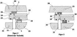
- pressure pieces 10 are used to arrange and maintain the spacing of the hot runner body.
- a support body 12 as spacer elements, so that the hot runner body 10 maintains a defined distance from the rear clamping plate 24 and the front mold plate 25, with the hot runner nozzles 11 being guided through the mold plate 25 facing the cavity in the tool.
- the hot runner body 10 is heated by means of heating elements 22, which heat the hot runner body 10 to a temperature of 250° C to 300° C, for example, and maintain the temperature, while cooling water channels 21 are introduced into the clamping plate 24 and the mold plate 25 in order to cool them.
- the function of the injection mold can be maintained, while the clamping plate 24 and the mold plate 25 are cooled with cooling water channels 21.
- the pressure pieces 1 are arranged both between the hot runner body 10 and the clamping plate 24 and between the hot runner body 10 and the mold plate 25 and define a specific distance in each case.
- the pressure pieces 1 are screwed to the hot runner body 10 with screw elements 23.
- the DE 2 160 535 A1 discloses pressure pieces for injection molds, which are designed as clamping nuts, for example, and which are used for arrangement between a hot runner body and the respective conversion parts, in particular a clamping plate and a mold plate.
- the pressure pieces have a support body for absorbing forces acting on the hot runner body.
- the disadvantage is that there is a significant flow of heat between the hot runner body and the clamping plate and/or the mold plate via the support bodies of the pressure pieces.
- the hot runner body must be kept at the temperature in order to keep the plastic mass in the plasticized state, and on the other hand, the clamping plate and the mold plate must be cooled accordingly.
- the pressure pieces must also be designed to withstand high mechanical loads in order to be able to absorb the considerable pressure forces that can act on the hot runner body when the tool is in operation.
- the object of the invention is an improved design of a pressure piece for arrangement on or in connection with a hot runner body of an injection mold, in particular a hot runner manifold, a manifold plate or a manifold block.
- the pressure piece is to be further developed in such a way that high operating forces of the injection mold can be supported by the pressure pieces, at the same time the heat flow from the hot runner body into the clamping plate and/or into the mold plate can be minimized.
- the invention includes the technical teaching that the support body of the pressure piece is produced by means of a generative manufacturing process and has a hollow chamber structure, wherein the hollow chamber structure of the support body has webs and openings formed between the webs, wherein the webs of the hollow chamber structure have a wall thickness that increases starting from a central region in the direction of contact surfaces of the pressure piece.
- Generative manufacturing processes are also referred to as 3D printing processes, and the SLM (Selective Laser Melting) process can be considered a preferred generative manufacturing process for producing the printed part.
- SLM Selective Laser Melting
- Such a generative manufacturing process enables a free geometric design of the support body made of a metallic material, which goes beyond the possibilities of conventional manufacturing.
- the particular advantage that can be used here is that the printed part can be made with a support body that is designed in such a way that the support body can support high mechanical forces, but at the same time enables very good thermal insulation of the hot runner body from the clamping plate and/or from the mold plate.
- the pressure piece produced in the generative manufacturing process can be provided as an individual part within the scope of the invention, whereby it is also conceivable that the pressure piece can be built up, for example, on the surface of the hot runner body, the clamping plate and/or the mold plate in the generative process.
- the pressure piece can therefore also be formed in one piece with the hot runner body, the clamping plate and/or the mold plate or another component of an injection mold.
- the support body is preferably manufactured with a hollow chamber structure using a generative manufacturing process, and the hollow chamber structure is designed in such a way that high support forces can be introduced into the pressure piece, but at the same time the heat conduction cross-section is small in order to minimize heat conduction from the hot runner body to the receiving plate and/or the mold plate.
- the support body is designed with a first contact surface and a second contact surface that is also flat and is parallel to the first contact surface, with the hollow chamber structure extending essentially uniformly between the first and second contact surfaces.
- the hollow chamber structure is created in that it is formed by thin webs that enclose respective openings. The openings are thus formed as hollow chambers between the webs, with the webs being able to form flat surface sections or the webs being able to have curves or non-uniform wall thicknesses.
- the hollow chamber structure can form a honeycomb structure, whereby the honeycombs each have a hexagonal basic shape, which Basic cross-section of the openings between the webs. It is also conceivable that the hollow chamber structures have cylindrical openings, between which the webs form a solid material, so to speak, and therefore do not have a uniform wall thickness. On the other hand, the webs in a honeycomb structure can have a uniform wall thickness, and the hollow chambers, i.e. the cylindrical openings or the hexagonal honeycomb structure openings, extend uniformly between the first contact surface and the second contact surface.
- the support body has a hexagonal and in particular closed outer contour between the first and second contact surfaces.
- the compressive load capacity of the support body can be further increased by a closed outer contour, whereby a hexagonal outer contour of the support body is particularly advantageous if the hollow chamber structure has a honeycomb structure.
- the support body can have a central depression starting from the first contact surface, and with further advantage a passage is introduced between the bottom of the depression and the second contact surface in order to guide a fastening means through this passage.
- the fastening means is preferably designed in the form of a screw element, wherein the support body can be arranged on the hot runner body with the second contact surface abutting.
- the webs of the hollow chamber structure have a wall thickness in the area of the support surfaces that is greater than over the essential length in the middle area, so that the wall thickness increases slightly in the direction of the contact surfaces.
- the support body has, for example, a dimension according to which the distance between the two contact surfaces is between 10 mm and 30 mm. Depending on the design, dimensions for the support body can also be between 5 mm and 50 mm, for example. If the support body has a hexagonal outer contour, the dimension between two flat surfaces of the hexagonal outer contour can be, for example, 20 mm to 30 mm, preferably 24 mm to 28 mm and/or 26 mm. For large mold construction, it is also conceivable within the scope of the present invention that the pressure piece has main dimensions of up to 200 mm or even significantly more.
- the wall thickness of the webs is above the essential height of the pressure hull between the two contact surfaces 0.2 mm to 1 mm and/or 0.2 mm to 0.4 mm and preferably 0.3 mm and/or approximately or exactly 0.3 mm. Adjacent to the contact surfaces, the wall thickness of the webs can be increased over the last, for example 2 remaining mm up to the contact surface up to 0.45 mm to 0.6 mm and preferably approximately or exactly 0.52 mm.
- the material of the support body preferably comprises a tool steel, wherein the support body is in particular made of the same material and in one piece.
- tool steel can be processed using a generative manufacturing process, in particular using the SLM process.
- the material of the support body preferably comprises a steel with the specification 1.2709 or X3NiCoMoTi18-9-5 and/or a titanium material Ti6AI4V. Other materials that can be produced using a generative manufacturing process are also included in the scope of the present invention.
- the invention is further directed to an injection mold with at least one pressure piece that is designed to be arranged on or in connection with a hot runner body of the injection mold, to which at least one hot runner nozzle can be attached, wherein the pressure piece has a support body for absorbing forces acting on the hot runner body.
- the support body is manufactured using a generative manufacturing process.
- FIG. 1 A perspective view of a hot runner body 10 in the form of a plate-shaped hot runner distributor is shown.
- Several hot runner nozzles 11 are arranged on the hot runner body 10, which can be supplied with a plasticized plastic melt via melt channels 20 formed in the hot runner body 10.
- the hot runner body 10 has heating elements 22 which keep it at a temperature of, for example, 270° C.
- the hot runner body 10 shown is inserted into the component assembly of an injection mold, for which pressure pieces 1 are provided in order to set up the hot runner body 10 at a certain distance from the conversion parts.
- the hot runner body 10 has several pressure pieces 1 screwed on by means of screw elements 23, wherein the pressure pieces 1 shown have a design according to the invention.
- Figure 2 represents the state of the art and has already been described in the introductory section above.
- Figure 3 shows the arrangement of the plate-shaped hot runner body 10 between a clamping plate 24 and a mold plate 25, the latter forming part of the actual injection molding tool.
- the hot runner body 10 can also have a cubic shape, a polygonal plate shape or another shape and is inserted at a certain distance from both the clamping plate 24 and the mold plate 25 with a pressure piece 1, the pressure pieces 1 being screwed to the hot runner body 10 by means of screw elements 23.
- the cross-sectional view also shows the melt channel 20 for supplying the hot runner nozzle 11.
- the hot runner body 10 is heated by means of heating elements 22, while the clamping plate 24 and the mold plate 25 are cooled by means of cooling water channels 21 through which a cooling medium can flow.
- the view illustrates the task of thermal insulation that is to be implemented by the pressure pieces 1.
- the hot hot runner body 10 must be insulated from the clamping plate 24 and the mold plate 25, but at the same time high pressure forces must be absorbed between the mold plate 25 and the hot runner body 10 or the clamping plate 24. Consequently, the pressure pieces 1 must be designed to be mechanically stable, while at the same time offering the best possible thermal insulation so that the hot runner body 10 does not cool down unnecessarily on the clamping plate 24 and/or the mold plate 25.
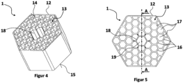
- Figure 4 shows a perspective view of the pressure piece 1 produced according to the invention based on a generative manufacturing process.
- the pressure piece 1 has a support body 12, which is delimited on the top and bottom by a contact surface 14, 15. With the contact surfaces 14, 15, the pressure piece 1 can rest on the hot runner body 10 or on the clamping plate 24 and/or on the mold plate 25.
- the support body 12 is as in Figure 5 shown with a hollow chamber structure, wherein the hollow chamber structure 13 comprises webs 16 and openings 17 formed between the webs.
- the structure is designed such that the webs 16 form a honeycomb structure with the openings 17, such that the openings 17 have a hexagonal cross-sectional shape.
- the support body 12 has a recess 18 with an inner passage 19 so that a screw element with a screw head can be inserted into the recess 18 and the screw shaft can be guided through the passage 19.
- the outer circumference of the support body 12 also has a hexagonal structure, wherein the hollow chamber structure 13 is uniformly designed over the thickness of the support body 12 from contact surface 14 to contact surface 15.
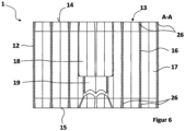
- Figure 6 shows the cross-sectional view of the support body 12 of the pressure piece 1 along the section line AA according to Figure 5
- the illustration shows cross-sectioned webs 16 and associated openings 17 in between of the hollow chamber structure 13. This once again illustrates the uniform design of the hollow chamber structure 13 from the first contact surface 14 to the opposite second contact surface 15, wherein the webs 16 have thickenings 26 formed up to the contact surfaces 14 and 15 and projecting thereto, so that the contact surfaces 14 and 15 have a larger area than the central cross section of the support body 12.
- the illustration also shows the recess 18 with the passage 19 for receiving the screw element.
- this shows that the webs 16 of the hollow chamber structure 13 according to the invention have a wall thickness in the area of the support surfaces 14, 15 that is greater than over the essential length in the middle area, so that the wall thickness increases slightly in the direction of the contact surfaces 14, 15.
- This creates the advantage that the contact surfaces are formed by the cross-sectional structure, and therefore the cross-sectional profile, of the hollow chamber structure.
- Increasing the wall thickness of the webs 16 up to the support surface 14, 15 results in an enlargement of the contact surfaces 14, 15, so that a better transfer of force from the support body 12 to the clamping plate or to the mold plate can take place, since the effective contact area is increased by the thicker webs 16 of the hollow chamber structure 13.
Landscapes
- Engineering & Computer Science (AREA)
- Manufacturing & Machinery (AREA)
- Mechanical Engineering (AREA)
- Moulds For Moulding Plastics Or The Like (AREA)
Claims (12)
- Pièce de pression (1) pour moules pour moulage par injection, conçue pour être agencée sur ou en liaison avec un corps de canal chaud (10), sur lequel au moins une buse de canal chaud (11) peut être montée, la pièce de pression (1) présentant un corps de support (12) destiné à absorber des forces agissant sur le corps de canal chaud (10),- le corps de support (12) étant fabriqué au moyen d'un procédé de fabrication additive,- le corps de support (12) présentant une structure alvéolée (13),- caractérisée
en ce que
la structure alvéolée (13) du corps de support (12) présente des cloisons (16) et des ouvertures (17) réalisées entre les cloisons (16),- les cloisons (16) de la structure alvéolée (13) présentent une épaisseur de paroi qui augmente à partir d'une zone centrale en direction de surfaces d'appui (14, 15) de la pièce de pression (1). - Pièce de pression (1) selon la revendication 1,
caractérisée en ce que
le corps de support (12) est réalisé d'un seul tenant. - Pièce de pression (1) selon la revendication 1 ou 2,
caractérisée en ce que
le corps de support (12) présente une première surface d'appui (14) et une seconde surface d'appui (15) réalisée parallèle à la première surface d'appui (14), la structure alvéolée (13) s'étendant sensiblement de manière uniforme entre la première et la seconde surface d'appui (14, 15). - Pièce de pression (1) selon l'une des revendications précédentes, caractérisée en ce que
la structure alvéolée (13) présente une structure en nids d'abeilles, les nids d'abeilles présentant chacun une forme de base hexagonale. - Pièce de pression (1) selon l'une des revendications précédentes, caractérisée en ce que
le corps de support (12) présente un contour externe hexagonal et/ou fermé entre la première et la seconde surface d'appui (14, 15). - Pièce de pression (1) selon l'une des revendications précédentes, caractérisée en ce que
le corps de support (12) présente, partant de la première surface d'appui (14), un creux (18) central et dans laquelle un passage (19) est situé entre le fond du creux et la seconde surface d'appui (15) pour faire passer un moyen de fixation à travers celle-ci. - Pièce de pression (1) selon l'une des revendications précédentes, caractérisée en ce que
le corps de support (12) présente une dimension selon laquelle la distance entre les deux surfaces d'appui (14, 15) présente une valeur de 10 mm à 30 mm. - Pièce de pression (1) selon l'une des revendications précédentes, caractérisée en ce que
les cloisons (16) de la structure alvéolée (13) présentent, sur l'essentiel de leur longueur entre les deux surfaces d'appui (14, 15), une épaisseur de paroi de 0,2 mm à 0,4 mm et de préférence de 0,3 mm et/ou en ce que l'épaisseur de paroi des cloisons (16) de la structure alvéolée (13) à côté ou dans la zone des surfaces d'appui (14, 15) est de 0,45 mm à 0,6 mm et de préférence de 0,52 mm. - Pièce de pression (1) selon l'une des revendications précédentes, caractérisée en ce que
le matériau du corps de support (12) présente un acier à outils. - Pièce de pression (1) selon l'une des revendications précédentes, caractérisée en ce que
le matériau du corps de support (12) présente un acier de spécification 1.2709 ou X3NiCoMoTi18-9-5 et/ou un matériau à base de titane Ti6AI4V. - Pièce de pression (1) selon l'une des revendications précédentes, caractérisée en ce que
les surfaces d'appui (14, 15) sont formées à partir des faces frontales des cloisons (16). - Moule pour moulage par injection comportant au moins une pièce de pression (1) qui est conçue pour être agencée sur ou en liaison avec un corps de canal chaud (10) du moule pour moulage par injection, sur lequel au moins une buse de canal chaud (11) peut être montée, la pièce de pression (1) présentant un corps de support (12) destiné à absorber des forces agissant sur le corps de canal chaud (10),- le corps de support (12) étant fabriqué au moyen d'un procédé de fabrication additive,- le corps de support (12) présentant une structure alvéolée (13),- caractérisé en ce que
la structure alvéolée (13) du corps de support (12) présente des cloisons (16) et des ouvertures (17) réalisées entre les cloisons (16),- les cloisons (16) de la structure alvéolée (13) présentent une épaisseur de paroi qui augmente à partir d'une zone centrale en direction de surfaces d'appui (14, 15) de la pièce de pression (1).
Priority Applications (2)
| Application Number | Priority Date | Filing Date | Title |
|---|---|---|---|
| ES21217870T ES2991679T3 (es) | 2021-12-27 | 2021-12-27 | Pieza de presión para moldes de inyección |
| EP21217870.1A EP4201633B1 (fr) | 2021-12-27 | 2021-12-27 | Pièce de pression pour moules pour moulage par injection |
Applications Claiming Priority (1)
| Application Number | Priority Date | Filing Date | Title |
|---|---|---|---|
| EP21217870.1A EP4201633B1 (fr) | 2021-12-27 | 2021-12-27 | Pièce de pression pour moules pour moulage par injection |
Publications (3)
| Publication Number | Publication Date |
|---|---|
| EP4201633A1 EP4201633A1 (fr) | 2023-06-28 |
| EP4201633B1 true EP4201633B1 (fr) | 2024-08-14 |
| EP4201633C0 EP4201633C0 (fr) | 2024-08-14 |
Family
ID=79170725
Family Applications (1)
| Application Number | Title | Priority Date | Filing Date |
|---|---|---|---|
| EP21217870.1A Active EP4201633B1 (fr) | 2021-12-27 | 2021-12-27 | Pièce de pression pour moules pour moulage par injection |
Country Status (2)
| Country | Link |
|---|---|
| EP (1) | EP4201633B1 (fr) |
| ES (1) | ES2991679T3 (fr) |
Family Cites Families (5)
| Publication number | Priority date | Publication date | Assignee | Title |
|---|---|---|---|---|
| DE2160535A1 (de) | 1971-12-07 | 1973-06-20 | Strack Gmbh Norma | Heisskanal-spritzgusswerkzeug |
| JP2730305B2 (ja) * | 1991-03-14 | 1998-03-25 | 三菱マテリアル株式会社 | ホットランナー式成形装置 |
| US5217730A (en) * | 1992-05-04 | 1993-06-08 | Alex C. Teng | Multi-cavity injection molding heated nozzle |
| WO2017201611A1 (fr) * | 2016-05-27 | 2017-11-30 | Husky Injection Molding Systems Ltd. | Structures d'obturateur de moule |
| CN209775380U (zh) * | 2019-04-12 | 2019-12-13 | 柳道万和(苏州)热流道系统有限公司 | 注射嘴及具有其的注塑机 |
-
2021
- 2021-12-27 ES ES21217870T patent/ES2991679T3/es active Active
- 2021-12-27 EP EP21217870.1A patent/EP4201633B1/fr active Active
Also Published As
| Publication number | Publication date |
|---|---|
| EP4201633A1 (fr) | 2023-06-28 |
| ES2991679T3 (es) | 2024-12-04 |
| EP4201633C0 (fr) | 2024-08-14 |
Similar Documents
| Publication | Publication Date | Title |
|---|---|---|
| DE102007054723B4 (de) | Formteil | |
| EP2004382B1 (fr) | Outil de moulage par injection à canaux chauds avec buse de fermeture à aiguille | |
| AT516225B1 (de) | Verfahren und Spritzgussdüse zum Herstellen von Spritzgussteilen aus Kunststoff | |
| EP0824057A1 (fr) | Procédé et dispositif pour fabriquer des articles moulés par injection en matière plastique | |
| DE10353696A1 (de) | Düse mit Wärmeleitvorrichtung | |
| DE3935856C1 (fr) | ||
| DE202010002328U1 (de) | Formwerkzeug | |
| EP2781333B1 (fr) | Composants pour un outil de moulage par injection, outil de moulage par injection et procédé de fabrication des composants | |
| EP4201633B1 (fr) | Pièce de pression pour moules pour moulage par injection | |
| EP2623233B1 (fr) | Procédé de fabrication de pièces creuses coulées sous pression en aluminium | |
| EP0818295A1 (fr) | Système à buse à obturateur à aiguille pour un dispositif de moulage par injection de matière plastique, notamment pour travailler des caoutchoucs de silicone | |
| EP1239998B1 (fr) | Systeme distributeur pour canaux chauffants | |
| DE3143748C2 (de) | Form zum Spritzgießen oder Preßspritzen von Kautschuk oder anderen plastischen, wärmehärtbaren Werkstoffen | |
| DE102009037343A1 (de) | Heißkanaldüse | |
| EP0700766B1 (fr) | Dispositif pour fabriquer des articles moulés par injection | |
| DE19627176C2 (de) | Vorrichtung zum Spritzgießen mit auswechselbaren Formleisten | |
| EP4403331B1 (fr) | Corps isolant et outil de moulage par injection doté d'un tel corps isolant | |
| EP3281762B1 (fr) | Machine à moulage par injection comprenant plaques d'adaptateur | |
| EP4296030B1 (fr) | Corps de réception destiné à la réception d'une buse de canal chauffant et outil de moulage par injection | |
| EP2045065A2 (fr) | Moule de moulage par injection destiné à être utilisé dans un dispositif de moulage par injection | |
| DE10331642A1 (de) | Vorrichtung zum Spritzgießen von Formkörpern aus Kunststoff | |
| DE102019127956A1 (de) | Seitenanspritzdüse und spritzgiesswerkzeug | |
| EP4464495A1 (fr) | Verrou de buse, ensemble buse, outil de moulage par injection et procédé de moulage par injection pour fabriquer un produit | |
| DE102023130949A1 (de) | Werkzeug zum Spritzgießen von Kunststoffteilen und Verfahren zu dessen Betrieb | |
| EP4464494A1 (fr) | Ensemble buse et procédé de moulage par injection |
Legal Events
| Date | Code | Title | Description |
|---|---|---|---|
| STAA | Information on the status of an ep patent application or granted ep patent |
Free format text: STATUS: EXAMINATION IS IN PROGRESS |
|
| PUAI | Public reference made under article 153(3) epc to a published international application that has entered the european phase |
Free format text: ORIGINAL CODE: 0009012 |
|
| 17P | Request for examination filed |
Effective date: 20221006 |
|
| AK | Designated contracting states |
Kind code of ref document: A1 Designated state(s): AL AT BE BG CH CY CZ DE DK EE ES FI FR GB GR HR HU IE IS IT LI LT LU LV MC MK MT NL NO PL PT RO RS SE SI SK SM TR |
|
| GRAP | Despatch of communication of intention to grant a patent |
Free format text: ORIGINAL CODE: EPIDOSNIGR1 |
|
| STAA | Information on the status of an ep patent application or granted ep patent |
Free format text: STATUS: GRANT OF PATENT IS INTENDED |
|
| INTG | Intention to grant announced |
Effective date: 20240318 |
|
| GRAS | Grant fee paid |
Free format text: ORIGINAL CODE: EPIDOSNIGR3 |
|
| GRAA | (expected) grant |
Free format text: ORIGINAL CODE: 0009210 |
|
| STAA | Information on the status of an ep patent application or granted ep patent |
Free format text: STATUS: THE PATENT HAS BEEN GRANTED |
|
| AK | Designated contracting states |
Kind code of ref document: B1 Designated state(s): AL AT BE BG CH CY CZ DE DK EE ES FI FR GB GR HR HU IE IS IT LI LT LU LV MC MK MT NL NO PL PT RO RS SE SI SK SM TR |
|
| REG | Reference to a national code |
Ref country code: GB Ref legal event code: FG4D Free format text: NOT ENGLISH |
|
| REG | Reference to a national code |
Ref country code: CH Ref legal event code: EP |
|
| REG | Reference to a national code |
Ref country code: DE Ref legal event code: R096 Ref document number: 502021004777 Country of ref document: DE |
|
| REG | Reference to a national code |
Ref country code: IE Ref legal event code: FG4D Free format text: LANGUAGE OF EP DOCUMENT: GERMAN |
|
| U01 | Request for unitary effect filed |
Effective date: 20240815 |
|
| U07 | Unitary effect registered |
Designated state(s): AT BE BG DE DK EE FI FR IT LT LU LV MT NL PT SE SI Effective date: 20240828 |
|
| REG | Reference to a national code |
Ref country code: ES Ref legal event code: FG2A Ref document number: 2991679 Country of ref document: ES Kind code of ref document: T3 Effective date: 20241204 |
|
| PG25 | Lapsed in a contracting state [announced via postgrant information from national office to epo] |
Ref country code: NO Free format text: LAPSE BECAUSE OF FAILURE TO SUBMIT A TRANSLATION OF THE DESCRIPTION OR TO PAY THE FEE WITHIN THE PRESCRIBED TIME-LIMIT Effective date: 20241114 |
|
| PG25 | Lapsed in a contracting state [announced via postgrant information from national office to epo] |
Ref country code: GR Free format text: LAPSE BECAUSE OF FAILURE TO SUBMIT A TRANSLATION OF THE DESCRIPTION OR TO PAY THE FEE WITHIN THE PRESCRIBED TIME-LIMIT Effective date: 20241115 |
|
| PGFP | Annual fee paid to national office [announced via postgrant information from national office to epo] |
Ref country code: PL Payment date: 20241120 Year of fee payment: 4 |
|
| PG25 | Lapsed in a contracting state [announced via postgrant information from national office to epo] |
Ref country code: IS Free format text: LAPSE BECAUSE OF FAILURE TO SUBMIT A TRANSLATION OF THE DESCRIPTION OR TO PAY THE FEE WITHIN THE PRESCRIBED TIME-LIMIT Effective date: 20241214 |
|
| PG25 | Lapsed in a contracting state [announced via postgrant information from national office to epo] |
Ref country code: HR Free format text: LAPSE BECAUSE OF FAILURE TO SUBMIT A TRANSLATION OF THE DESCRIPTION OR TO PAY THE FEE WITHIN THE PRESCRIBED TIME-LIMIT Effective date: 20240814 |
|
| PGFP | Annual fee paid to national office [announced via postgrant information from national office to epo] |
Ref country code: CZ Payment date: 20241219 Year of fee payment: 4 |
|
| PG25 | Lapsed in a contracting state [announced via postgrant information from national office to epo] |
Ref country code: RS Free format text: LAPSE BECAUSE OF FAILURE TO SUBMIT A TRANSLATION OF THE DESCRIPTION OR TO PAY THE FEE WITHIN THE PRESCRIBED TIME-LIMIT Effective date: 20241114 |
|
| PG25 | Lapsed in a contracting state [announced via postgrant information from national office to epo] |
Ref country code: RS Free format text: LAPSE BECAUSE OF FAILURE TO SUBMIT A TRANSLATION OF THE DESCRIPTION OR TO PAY THE FEE WITHIN THE PRESCRIBED TIME-LIMIT Effective date: 20241114 Ref country code: NO Free format text: LAPSE BECAUSE OF FAILURE TO SUBMIT A TRANSLATION OF THE DESCRIPTION OR TO PAY THE FEE WITHIN THE PRESCRIBED TIME-LIMIT Effective date: 20241114 Ref country code: IS Free format text: LAPSE BECAUSE OF FAILURE TO SUBMIT A TRANSLATION OF THE DESCRIPTION OR TO PAY THE FEE WITHIN THE PRESCRIBED TIME-LIMIT Effective date: 20241214 Ref country code: HR Free format text: LAPSE BECAUSE OF FAILURE TO SUBMIT A TRANSLATION OF THE DESCRIPTION OR TO PAY THE FEE WITHIN THE PRESCRIBED TIME-LIMIT Effective date: 20240814 Ref country code: GR Free format text: LAPSE BECAUSE OF FAILURE TO SUBMIT A TRANSLATION OF THE DESCRIPTION OR TO PAY THE FEE WITHIN THE PRESCRIBED TIME-LIMIT Effective date: 20241115 |
|
| U20 | Renewal fee for the european patent with unitary effect paid |
Year of fee payment: 4 Effective date: 20241227 |
|
| PG25 | Lapsed in a contracting state [announced via postgrant information from national office to epo] |
Ref country code: SM Free format text: LAPSE BECAUSE OF FAILURE TO SUBMIT A TRANSLATION OF THE DESCRIPTION OR TO PAY THE FEE WITHIN THE PRESCRIBED TIME-LIMIT Effective date: 20240814 |
|
| PGFP | Annual fee paid to national office [announced via postgrant information from national office to epo] |
Ref country code: ES Payment date: 20250131 Year of fee payment: 4 |
|
| PG25 | Lapsed in a contracting state [announced via postgrant information from national office to epo] |
Ref country code: SK Free format text: LAPSE BECAUSE OF FAILURE TO SUBMIT A TRANSLATION OF THE DESCRIPTION OR TO PAY THE FEE WITHIN THE PRESCRIBED TIME-LIMIT Effective date: 20240814 |
|
| PLBE | No opposition filed within time limit |
Free format text: ORIGINAL CODE: 0009261 |
|
| STAA | Information on the status of an ep patent application or granted ep patent |
Free format text: STATUS: NO OPPOSITION FILED WITHIN TIME LIMIT |
|
| PG25 | Lapsed in a contracting state [announced via postgrant information from national office to epo] |
Ref country code: MC Free format text: LAPSE BECAUSE OF FAILURE TO SUBMIT A TRANSLATION OF THE DESCRIPTION OR TO PAY THE FEE WITHIN THE PRESCRIBED TIME-LIMIT Effective date: 20240814 |
|
| 26N | No opposition filed |
Effective date: 20250515 |
|
| REG | Reference to a national code |
Ref country code: CH Ref legal event code: PL |
|
| PG25 | Lapsed in a contracting state [announced via postgrant information from national office to epo] |
Ref country code: CH Free format text: LAPSE BECAUSE OF NON-PAYMENT OF DUE FEES Effective date: 20241231 |
|
| PG25 | Lapsed in a contracting state [announced via postgrant information from national office to epo] |
Ref country code: IE Free format text: LAPSE BECAUSE OF NON-PAYMENT OF DUE FEES Effective date: 20241227 |
|
| PG25 | Lapsed in a contracting state [announced via postgrant information from national office to epo] |
Ref country code: RO Free format text: LAPSE BECAUSE OF FAILURE TO SUBMIT A TRANSLATION OF THE DESCRIPTION OR TO PAY THE FEE WITHIN THE PRESCRIBED TIME-LIMIT Effective date: 20240814 |