EP4201615B1 - Hochgeschwindigkeits-hydraulikschneidemaschine mit intelligenter numerischer steuerung - Google Patents
Hochgeschwindigkeits-hydraulikschneidemaschine mit intelligenter numerischer steuerung Download PDFInfo
- Publication number
- EP4201615B1 EP4201615B1 EP21942798.6A EP21942798A EP4201615B1 EP 4201615 B1 EP4201615 B1 EP 4201615B1 EP 21942798 A EP21942798 A EP 21942798A EP 4201615 B1 EP4201615 B1 EP 4201615B1
- Authority
- EP
- European Patent Office
- Prior art keywords
- die cutter
- die
- fixing plate
- disposed
- limiting
- Prior art date
- Legal status (The legal status is an assumption and is not a legal conclusion. Google has not performed a legal analysis and makes no representation as to the accuracy of the status listed.)
- Active
Links
Images
Classifications
-
- B—PERFORMING OPERATIONS; TRANSPORTING
- B26—HAND CUTTING TOOLS; CUTTING; SEVERING
- B26D—CUTTING; DETAILS COMMON TO MACHINES FOR PERFORATING, PUNCHING, CUTTING-OUT, STAMPING-OUT OR SEVERING
- B26D7/00—Details of apparatus for cutting, cutting-out, stamping-out, punching, perforating, or severing by means other than cutting
- B26D7/26—Means for mounting or adjusting the cutting member; Means for adjusting the stroke of the cutting member
- B26D7/2614—Means for mounting the cutting member
-
- B—PERFORMING OPERATIONS; TRANSPORTING
- B26—HAND CUTTING TOOLS; CUTTING; SEVERING
- B26D—CUTTING; DETAILS COMMON TO MACHINES FOR PERFORATING, PUNCHING, CUTTING-OUT, STAMPING-OUT OR SEVERING
- B26D7/00—Details of apparatus for cutting, cutting-out, stamping-out, punching, perforating, or severing by means other than cutting
- B26D7/26—Means for mounting or adjusting the cutting member; Means for adjusting the stroke of the cutting member
-
- B—PERFORMING OPERATIONS; TRANSPORTING
- B21—MECHANICAL METAL-WORKING WITHOUT ESSENTIALLY REMOVING MATERIAL; PUNCHING METAL
- B21D—WORKING OR PROCESSING OF SHEET METAL OR METAL TUBES, RODS OR PROFILES WITHOUT ESSENTIALLY REMOVING MATERIAL; PUNCHING METAL
- B21D28/00—Shaping by press-cutting; Perforating
- B21D28/02—Punching blanks or articles with or without obtaining scrap; Notching
- B21D28/04—Centering the work; Positioning the tools
-
- B—PERFORMING OPERATIONS; TRANSPORTING
- B21—MECHANICAL METAL-WORKING WITHOUT ESSENTIALLY REMOVING MATERIAL; PUNCHING METAL
- B21D—WORKING OR PROCESSING OF SHEET METAL OR METAL TUBES, RODS OR PROFILES WITHOUT ESSENTIALLY REMOVING MATERIAL; PUNCHING METAL
- B21D28/00—Shaping by press-cutting; Perforating
- B21D28/02—Punching blanks or articles with or without obtaining scrap; Notching
- B21D28/14—Dies
-
- B—PERFORMING OPERATIONS; TRANSPORTING
- B21—MECHANICAL METAL-WORKING WITHOUT ESSENTIALLY REMOVING MATERIAL; PUNCHING METAL
- B21D—WORKING OR PROCESSING OF SHEET METAL OR METAL TUBES, RODS OR PROFILES WITHOUT ESSENTIALLY REMOVING MATERIAL; PUNCHING METAL
- B21D28/00—Shaping by press-cutting; Perforating
- B21D28/24—Perforating, i.e. punching holes
- B21D28/34—Perforating tools; Die holders
-
- B—PERFORMING OPERATIONS; TRANSPORTING
- B21—MECHANICAL METAL-WORKING WITHOUT ESSENTIALLY REMOVING MATERIAL; PUNCHING METAL
- B21D—WORKING OR PROCESSING OF SHEET METAL OR METAL TUBES, RODS OR PROFILES WITHOUT ESSENTIALLY REMOVING MATERIAL; PUNCHING METAL
- B21D37/00—Tools as parts of machines covered by this subclass
- B21D37/04—Movable or exchangeable mountings for tools
-
- B—PERFORMING OPERATIONS; TRANSPORTING
- B26—HAND CUTTING TOOLS; CUTTING; SEVERING
- B26D—CUTTING; DETAILS COMMON TO MACHINES FOR PERFORATING, PUNCHING, CUTTING-OUT, STAMPING-OUT OR SEVERING
- B26D5/00—Arrangements for operating and controlling machines or devices for cutting, cutting-out, stamping-out, punching, perforating, or severing by means other than cutting
- B26D5/02—Means for moving the cutting member into its operative position for cutting
- B26D5/04—Means for moving the cutting member into its operative position for cutting by fluid pressure
-
- B—PERFORMING OPERATIONS; TRANSPORTING
- B26—HAND CUTTING TOOLS; CUTTING; SEVERING
- B26F—PERFORATING; PUNCHING; CUTTING-OUT; STAMPING-OUT; SEVERING BY MEANS OTHER THAN CUTTING
- B26F1/00—Perforating; Punching; Cutting-out; Stamping-out; Apparatus therefor
- B26F1/38—Cutting-out; Stamping-out
- B26F1/40—Cutting-out; Stamping-out using a press, e.g. of the ram type
-
- B—PERFORMING OPERATIONS; TRANSPORTING
- B26—HAND CUTTING TOOLS; CUTTING; SEVERING
- B26D—CUTTING; DETAILS COMMON TO MACHINES FOR PERFORATING, PUNCHING, CUTTING-OUT, STAMPING-OUT OR SEVERING
- B26D7/00—Details of apparatus for cutting, cutting-out, stamping-out, punching, perforating, or severing by means other than cutting
- B26D7/26—Means for mounting or adjusting the cutting member; Means for adjusting the stroke of the cutting member
- B26D2007/2607—Means for mounting or adjusting the cutting member; Means for adjusting the stroke of the cutting member for mounting die cutters
Definitions
- the present invention relates to the technical field of cutting machines and in particular to a high-speed smart numerical control hydraulic cutting machine.
- the cutting machines requires frequency change of die cutters based on cutting patterns, and the die cutters are usually placed on die cutter plates.
- the die cutters are mostly changed manually, which leads to long change time and low efficiency.
- the position of the changed die cutters has poor repeatability and the size of the cut products is low in accuracy.
- some cutting machines adopt a mechanical device for automatic die cutter change, the mechanical device is complex in structure and the size accuracy of the cut products is still unsatisfactory.
- CN 106 734 503 A discloses a numerical control cutting machine, comprising a die cutter fixing plate and a die cutter for cutting an object, wherein a die cutter clamping and limiting device is disposed on the die cutter fixing plate to clamp the die cutter, wherein the die cutter clamping and limiting device comprises a clamping assembly and a limiting assembly which are mounted on the die cutter fixing plate, wherein the clamping assembly comprises pressing cylinders, wherein the limiting assembly comprises front limiting components and rear limiting components located at front and rear side surfaces of the die cutter fixing plate, wherein two pressing cylinders are disposed at the right and left sides of the die cutter fixing plate respectively, and wherein the two pressing cylinders act simultaneously to press or release the die cutter.
- the limiting components are used respectively to limit a maximum distance between the left die pressing plate/the right die pressing plate and the die cutter fixing plate.
- the present invention provides a high-speed smart numerical control hydraulic cutting machine to achieve clamping on a die cutter automatically and change the die cutter automatically. It is simple in structure and can shorten the time for changing the die cutter and noticeably improve the use rate of the cutting machine. Further, the position repeatability and the positioning accuracy of the die cutter are improved, and the size accuracy and stability of the cut products are also increased, so as to satisfy the users.
- the present invention is achieved by providing a high-speed smart numerical control hydraulic cutting machine, which includes a die cutter fixing plate and a die cutter for cutting an object.
- a die cutter clamping and limiting device is disposed on the die cutter fixing plate to clamp the die cutter.
- the die cutter clamping and limiting device includes a clamping assembly and a limiting assembly which are mounted on the die cutter fixing plate.
- the clamping assembly includes a left die pressing plate, a right die pressing plate, and pressing cylinders. The left die pressing plate and the right die pressing plate are disposed on the left and right side edges of a lower surface of the die cutter fixing plate respectively.
- the pressing cylinders are disposed inside the die cutter fixing plate and drive the left die pressing plate and the right die pressing plate respectively to press the die cutter closely against the lower surface of the die cutter fixing plate.
- the limiting assembly includes front limiting components and rear limiting components located at front and rear side surfaces of the die cutter fixing plate.
- the front limiting components perform limiting or unlocking for the front and rear side surfaces of the die cutter in linkage with the left die pressing plate or the right die pressing plate.
- Two pressing cylinders are disposed at the right and left sides of the die cutter fixing plate respectively. The two pressing cylinders act simultaneously to press or release the die cutter.
- Limiting screws are disposed between the left die pressing plate /the right die pressing plate and the die cutter fixing plate. The limiting screws are used to limit a maximum distance between the left die pressing plate/the right die pressing plate and the die cutter fixing plate.
- the pressing cylinder includes a cylindrical hole, a valve core shaft, an upper piston, a lower piston, an upper air chamber and a lower air chamber, where the cylindrical hole is disposed inside the die cutter fixing plate, and the valve core shaft, the upper piston, the lower piston, the upper air chamber and the lower air chamber are disposed inside the cylindrical hole.
- the upper piston and the lower piston are disposed on the valve core shaft respectively.
- the upper air chamber is disposed between the upper piston and the top wall of the cylindrical hole.
- the lower air chamber is disposed between the upper piston and the lower piston.
- An upper air pipe connector and a lower air pipe connector are disposed on the die cutter fixing plate respectively.
- the upper air pipe connector and the lower air pipe connector are in communication with the upper air chamber and the lower air chamber through an upper channel and a lower channel disposed in the die cutter fixing plate.
- a stop washer is disposed on an inner wall of the cylindrical hole to limit a movement position of the lower piston.
- side covers 10 are also disposed on the die cutter fixing plate.
- the rear limiting component includes a limiting block and a fastening bolt.
- the limiting block limits the movement position of the die cutter, and the fastening bolt fixes the limiting block on a side surface of the die cutter fixing plate.
- the front limiting component includes a first connection bar, a second connection bar, a first rotary shaft, a second rotary shaft, and a third rotary shaft.
- the first rotary shaft is fixed on the die cutter fixing plate
- the third rotary shaft is fixed on the left die pressing plate or the right die pressing plate.
- the first rotary shaft is movable disposed in the middle of the first connection bar
- the second rotary shaft movably connects an end of the first connection bar to an end of the second connection bar.
- a blocking portion is disposed on the other end of the first connection bar to limit the die cutter, and the other end of the second connection bar is movably connected with the third rotary shaft.
- one segment of inclined surface or arc-shaped surface is disposed on the blocking portion of the first connection bar.
- the high-speed smart numerical control hydraulic cutting machine includes the die cutter fixing plate and the die cutter for cutting an object.
- a die cutter clamping and limiting device is disposed on the die cutter fixing plate to clamp the die cutter.
- the die cutter clamping and limiting device includes the clamping assembly and the limiting assembly which are mounted on the die cutter fixing plate.
- the clamping assembly presses the die cutter closely against the lower surface of the die cutter fixing plate, and the limiting assembly limits the front and rear side surfaces of the die cutter.
- clamping on the die cutter and the change on the die cutter can be automatically achieved.
- the present invention is simple in structure and can shorten the time for changing the die cutter and noticeably improve the use rate of the cutting machine. Further, the position repeatability and the positioning accuracy of changing the die cutter are improved, and the size accuracy and stability of the cut products are also increased.
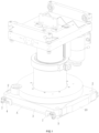
- a high-speed smart numerical control hydraulic cutting machine provided by the present invention includes a die cutter fixing plate and a die cutter A for cutting an object.
- a die cutter clamping and limiting device is disposed on the die cutter fixing plate 3 to clamp the die cutter.
- the die cutter clamping and limiting device includes a clamping assembly 1 and a limiting assembly which are mounted on the die cutter fixing plate 3.
- the clamping assembly 1 includes a left die pressing plate 4, a right die pressing plate 5, and pressing cylinders 6.
- the left die pressing plate 4 and the right die pressing plate 5 are disposed on the left and right side edges of a lower surface of the die cutter fixing plate 3 respectively.
- the pressing cylinders 6 are disposed inside the die cutter fixing plate 3 and located at four corners of the die cutter fixing plate 3 in a manner of left-right and back-front symmetry.
- the pressing cylinders 6 drive the left die pressing plate 4 and the right die pressing plate 5 respectively to press the die cutter A closely against the lower surface of the die cutter fixing plate 3.
- the limiting assembly includes front limiting components and rear limiting components located at front and rear side surfaces of the die cutter fixing plate 3, where the front limiting components 7 are movable limiting components and the rear limiting components are fixed limiting components.
- the front limiting components 7 perform limiting or unlocking for the front and rear side surfaces of the die cutter A in linkage with the left die pressing plate 4 or the right die pressing plate 5. As shown in FIGS. 1 , 2 , and 3 , the front limiting components 7 are respectively disposed at the front and rear side surfaces of the die cutter fixing plate 3.
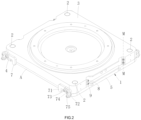
- the left die pressing plate 4 and the right die pressing plate 5 press the die cutter A closely against the lower surface of the die cutter fixing plate 3 along an up-down direction under the drive of the pressing cylinders 6.
- the limiting assembly performs limiting for the front and rear side surfaces of the die cutter A. In this way, the position repeatability and positioning accuracy of the die cutter is improved and the size accuracy of the cut products is also improved.
- the limiting assembly acts in the following process: when the left die pressing plate 4 and the right die pressing plate 5 of the clamping assembly 1 press the die cutter A closely against the lower surface of the die cutter fixing plate 3, the front limiting components 7 perform limiting for the front side surface and/or rear side surface of the die cutter A immediately. On the contrary, when the left die pressing plate 4 and the right die pressing plate 5 of the clamping assembly 1 release the up-down press on the die cutter A, the front limiting components 7 release limitation for the front side surface and/or the rear side surface of the die cutter A immediately.
- Two pressing cylinders 6 are disposed at the right and left sides of the die cutter fixing plate 3 respectively.
- the two pressing cylinders 6 act simultaneously to press or release the die cutter A.
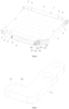
- the pressing cylinder 6 includes a cylindrical hole 61, a valve core shaft 62, an upper piston 63, a lower piston 64, an upper air chamber 65 and a lower air chamber 66, where the cylindrical hole 61 is disposed inside the die cutter fixing plate 3 and the valve core shaft 62, the upper piston 63, the lower piston 64, the upper air chamber 65 and the lower air chamber 66 are disposed inside the cylindrical hole 61.
- the upper piston 63 and the lower piston 64 are disposed on the valve core shaft 62 respectively.
- the upper air chamber 65 is disposed between the upper piston 63 and the top wall of the cylindrical hole 61.
- the lower air chamber 66 is disposed between the upper piston 63 and the lower piston 64.
- An upper air pipe connector 8 and a lower air pipe connector 9 are disposed on the die cutter fixing plate 3 respectively.
- the upper air pipe connector 8 and the lower air pipe connector 9 are in communication with the upper air chamber 65 and the lower air chamber 66 through an upper channel 67 and a lower channel 68 disposed in the die cutter fixing plate 3.
- the pressing cylinders 6 are directly made inside the die cutter fixing plate 3, which simplifies the structure of the die cutter clamping and limiting device, reduces the weight of the die cutter fixing plate 3 and improves its stability.
- the pressing cylinders 6 act in the following process: when high pressure air is introduced into the upper air chamber 65 via the upper air pipe connector 8, the lower air chamber 66 recovers air via the lower air pipe connector 9, and then the valve core shaft 62 is driven to move down together with the upper piston 63 and the lower piston 64 disposed thereon, and then the valve core shaft 62 pushes open the left die pressing plate 4 or the right die pressing plate 5, thereby unlocking the die cutter A.
- the upper air chamber 65 recovers air via the upper air pipe connector 8, and then the valve core shaft 62 is driven to move up for resetting together with the upper piston 63 and the lower piston 64 disposed thereon, and then the valve core shaft 62 drives the left die pressing plate 4 or the right die pressing plate 5 closely against the die cutter A.
- a stop washer 69 is disposed on an inner wall of the cylindrical hole 61 to limit a movement position of the lower piston 64, so as to limit a movement position of the valve core shaft 62, thereby limiting a telescoping height of the pressing cylinder 6.
- the rear limiting component includes a limiting block and a fastening bolt (not shown).
- the limiting block limits the movement position of the die cutter A, and the fastening bolt fixes the limiting block on a side surface of the die cutter fixing plate 3.
- the front limiting component 7 includes a first connection bar 71, a second connection bar 72, a first rotary shaft 73, a second rotary shaft 74, and a third rotary shaft 75.
- the first rotary shaft 73 is fixed on the die cutter fixing plate 3, and the third rotary shaft 75 is fixed on the left die pressing plate 4 or the right die pressing plate 5.
- the first rotary shaft 73 is movable disposed in the middle of the first connection bar 71, and the second rotary shaft 74 movably connects an end of the first connection bar 71 to an end of the second connection bar 72.
- a blocking portion 76 is disposed on the other end of the first connection bar 71 to limit the die cutter A, and the other end of the second connection bar 72 is movably connected with the third rotary shaft 75.
- one segment of inclined surface or arc-shaped surface 77 is disposed on the blocking portion 76 of the first connection bar 71, and thus it is convenient to push the die cutter A back to a correct limiting position when the first connection bar 71 performs limiting for the die cutter A.
- the front limiting component 7 acts in the following process: when the pressing cylinders 6 drive the left die pressing plate 4 or the right die pressing plate 5 to move down, the third rotary shaft 75 and the second connection bar 72 move down accordingly, and the second connection bar 72 also drives, via the second rotary shaft 74, an end of the first connection bar 71 to move down.
- the first connection bar 71 rotates around the first rotary shaft 73, so as to lift up the other end of the first connection bar 71, thus releasing the limited die cutter A.
- the third rotary shaft 75 and the second connection bar 72 move up accordingly, and the second connection bar 72 drives, via the second rotary shaft 74, an end of the first connection bar 71 to move up.
- the first connection bar 71 rotates around the first rotary shaft 73, so as to lower the other end of the first connection bar 71, thus limiting the die cutter A.
- Limiting screws 2 are disposed between the left die pressing plate 4/the right die pressing plate 5 and the die cutter fixing plate 3.
- the limiting screws 2 are used to adjust and limit a maximum distance between the left die pressing plate 4/the right die pressing plate 5 and the die cutter fixing plate 3.
- the die cutter A can be quickly limited and clamped, thus achieving quick change of the die cutter A. Further, good position repeatability and high positioning accuracy are ensured.
Landscapes
- Engineering & Computer Science (AREA)
- Mechanical Engineering (AREA)
- Life Sciences & Earth Sciences (AREA)
- Forests & Forestry (AREA)
- Physics & Mathematics (AREA)
- Fluid Mechanics (AREA)
- Mounting, Exchange, And Manufacturing Of Dies (AREA)
- Shearing Machines (AREA)
- Perforating, Stamping-Out Or Severing By Means Other Than Cutting (AREA)
Claims (7)
- Eine hochgeschwindigkeitsfähige, intelligente, numerisch gesteuerte hydraulische Schneidemaschine, umfassend eine Stanzmesser-Befestigungsplatte (3) und ein Stanzmesser (A) zum Schneiden eines Objekts, wobei eine Spann- und Begrenzungsvorrichtung für das Stanzmesser auf der Stanzmesser-Befestigungsplatte (3) angeordnet ist, um das Stanzmesser (A) zu spannen, wobei die Spann- und Begrenzungsvorrichtung ein Spannsystem (1) und ein Begrenzungssystem umfasst, die an der Stanzmesser-Befestigungsplatte (3) montiert sind, wobei das Spannsystem (1) eine linke Stanzpressplatte (4), eine rechte Stanzpressplatte (5) und Druckzylinder (6) umfasst, die linke Stanzpressplatte (4) und die rechte Stanzpressplatte (5) jeweils an den linken und rechten Seitenrändern einer unteren Fläche der Stanzmesser-Befestigungsplatte (3) angeordnet sind, die Druckzylinder (6) innerhalb der Stanzmesser-Befestigungsplatte (3) angeordnet sind und die linke Stanzpressplatte (4) und die rechte Stanzpressplatte (5) antreiben, das Stanzmesser (A) dicht gegen die untere Fläche der Stanzmesser-Befestigungsplatte (3) zu drücken, wobei das Begrenzungssystem vordere Begrenzungselemente (7) und hintere Begrenzungselemente umfasst, die sich an den vorderen und hinteren Seitenflächen der Stanzmesser-Befestigungsplatte (3) befinden, wobei die vorderen Begrenzungselemente (7) eine Begrenzung oder Entriegelung der vorderen und hinteren Seitenflächen des Stanzmessers (A) in Verbindung mit der linken Stanzpressplatte (4) oder der rechten Stanzpressplatte (5) durchführen, zwei Druckzylinder (6) jeweils an den rechten und linken Seiten der Stanzmesser-Befestigungsplatte (3) angeordnet sind, die zwei Druckzylinder (6) gleichzeitig wirken, um das Stanzmesser (A) zu drücken oder zu lösen, Begrenzungsschrauben (2) zwischen der linken Stanzpressplatte (4)/der rechten Stanzpressplatte (5) und der Stanzmesser-Befestigungsplatte (3) angeordnet sind, und die Begrenzungsschrauben (2) jeweils verwendet werden, um einen maximalen Abstand zwischen der linken Stanzpressplatte (4)/der rechten Stanzpressplatte (5) und der Stanzmesser-Befestigungsplatte (3) zu begrenzen.
- Die hochgeschwindigkeitsfähige, intelligente, numerisch gesteuerte hydraulische Schneidemaschine nach Anspruch 1, wobei der Druckzylinder (6) eine zylindrische Bohrung (61), eine Ventilkernwelle (62), einen oberen Kolben (63), einen unteren Kolben (64), eine obere Luftkammer (65) und eine untere Luftkammer (66) umfasst, die zylindrische Bohrung (61) sich innerhalb der Stanzmesser-Befestigungsplatte (3) befindet und die Ventilkernwelle (62), der obere Kolben (63), der untere Kolben (64), die obere Luftkammer (65) und die untere Luftkammer (66) sich innerhalb der zylindrischen Bohrung (61) befinden, der obere Kolben (63) und der untere Kolben (64) jeweils an der Ventilkernwelle (62) angeordnet sind, die obere Luftkammer (65) sich zwischen dem oberen Kolben (63) und der oberen Wand der zylindrischen Bohrung (61) befindet, die untere Luftkammer (66) sich zwischen dem oberen Kolben (63) und dem unteren Kolben (64) befindet, ein oberer Luftrohranschluss (8) und ein unterer Luftrohranschluss (9) sich jeweils auf der Stanzmesser-Befestigungsplatte (3) befinden, und der obere Luftrohranschluss (8) und der untere Luftrohranschluss (9) mit der oberen Luftkammer (65) und der unteren Luftkammer (66) durch einen oberen Kanal (67) und einen unteren Kanal (68), die in der Stanzmesser-Befestigungsplatte (3) angeordnet sind, in Kommunikation sind.
- Die hochgeschwindigkeitsfähige, intelligente, numerisch gesteuerte hydraulische Schneidemaschine nach Anspruch 2, wobei eine Anschlagunterlegscheibe (69) an einer Innenwand der zylindrischen Bohrung (61) angebracht ist, um eine Bewegungsposition des unteren Kolbens (64) zu begrenzen.
- Die hochgeschwindigkeitsfähige, intelligente, numerisch gesteuerte hydraulische Schneidemaschine nach Anspruch 2, wobei Seitenabdeckungen (10) zusätzlich an der Stanzmesser-Befestigungsplatte (3) angebracht sind.
- Die hochgeschwindigkeitsfähige, intelligente, numerisch gesteuerte hydraulische Schneidemaschine nach Anspruch 1, wobei das hintere Begrenzungselement einen Begrenzungsblock und eine Befestigungsschraube umfasst, der Begrenzungsblock die Bewegungsposition des Stanzmessers (A) begrenzt und die Befestigungsschraube den Begrenzungsblock an einer Seitenfläche der Stanzmesser-Befestigungsplatte (3) befestigt.
- Die hochgeschwindigkeitsfähige, intelligente, numerisch gesteuerte hydraulische Schneidemaschine nach Anspruch 1, wobei das vordere Begrenzungselement (7) eine erste Verbindungsstange (71), eine zweite Verbindungsstange (72), eine erste Drehachse (73), eine zweite Drehachse (74) und eine dritte Drehachse (75) umfasst, die erste Drehachse (73) an der Stanzmesser-Befestigungsplatte (3) befestigt ist, die dritte Drehachse (75) an der linken Stanzpressplatte (4) oder der rechten Stanzpressplatte (5) befestigt ist, die erste Drehachse (73) beweglich in der Mitte der ersten Verbindungsstange (71) angeordnet ist, die zweite Drehachse (74) ein Ende der ersten Verbindungsstange (71) mit einem Ende der zweiten Verbindungsstange (72) beweglich verbindet, ein Sperrteil (76) sich am anderen Ende der ersten Verbindungsstange (71) befindet, um das Stanzmesser (A) zu begrenzen, und das andere Ende der zweiten Verbindungsstange (72) beweglich mit der dritten Drehachse (75) verbunden ist.
- Die hochgeschwindigkeitsfähige, intelligente, numerisch gesteuerte hydraulische Schneidemaschine nach Anspruch 6, wobei ein Abschnitt einer geneigten Fläche oder einer bogenförmigen Fläche (77) auf dem Sperrteil (76) der ersten Verbindungsstange (71) angeordnet ist.
Applications Claiming Priority (2)
| Application Number | Priority Date | Filing Date | Title |
|---|---|---|---|
| CN202110567895.7A CN113172694A (zh) | 2021-05-24 | 2021-05-24 | 一种高速智能数控液压裁断机 |
| PCT/CN2021/138069 WO2022247235A1 (zh) | 2021-05-24 | 2021-12-14 | 一种高速智能数控液压裁断机 |
Publications (4)
| Publication Number | Publication Date |
|---|---|
| EP4201615A1 EP4201615A1 (de) | 2023-06-28 |
| EP4201615A4 EP4201615A4 (de) | 2024-02-21 |
| EP4201615B1 true EP4201615B1 (de) | 2025-02-12 |
| EP4201615C0 EP4201615C0 (de) | 2025-02-12 |
Family
ID=76930011
Family Applications (1)
| Application Number | Title | Priority Date | Filing Date |
|---|---|---|---|
| EP21942798.6A Active EP4201615B1 (de) | 2021-05-24 | 2021-12-14 | Hochgeschwindigkeits-hydraulikschneidemaschine mit intelligenter numerischer steuerung |
Country Status (3)
| Country | Link |
|---|---|
| EP (1) | EP4201615B1 (de) |
| CN (1) | CN113172694A (de) |
| WO (1) | WO2022247235A1 (de) |
Families Citing this family (2)
| Publication number | Priority date | Publication date | Assignee | Title |
|---|---|---|---|---|
| CN113510784A (zh) * | 2021-05-24 | 2021-10-19 | 衢州台威精工机械有限公司 | 刀模板夹紧限位装置以及使用该装置的裁断加工中心 |
| CN113172694A (zh) * | 2021-05-24 | 2021-07-27 | 衢州台威精工机械有限公司 | 一种高速智能数控液压裁断机 |
Family Cites Families (9)
| Publication number | Priority date | Publication date | Assignee | Title |
|---|---|---|---|---|
| JPH1071598A (ja) * | 1996-05-15 | 1998-03-17 | Daiji Adachi | 打抜型の交換・収納装置およびこれを備えた平盤打抜機 |
| CN1171993A (zh) * | 1997-03-31 | 1998-02-04 | 杨维雄 | 摇臂式下料机 |
| CN105216058B (zh) * | 2015-10-13 | 2017-03-01 | 盐城市华森机械有限公司 | 液压龙门裁断机自动刀模库 |
| CN206287240U (zh) * | 2016-11-25 | 2017-06-30 | 盐城市华森机械有限公司 | 一种旋转式冲压头的夹紧收废装置 |
| CN106734503B (zh) * | 2016-11-25 | 2018-07-10 | 盐城市华森机械有限公司 | 自动换刀模式异形材料冲裁机 |
| CN108466323A (zh) * | 2018-05-30 | 2018-08-31 | 盐城市裕正精密机械有限公司 | 裁断机刀模板自动夹紧机构 |
| CN113510784A (zh) * | 2021-05-24 | 2021-10-19 | 衢州台威精工机械有限公司 | 刀模板夹紧限位装置以及使用该装置的裁断加工中心 |
| CN113134863B (zh) * | 2021-05-24 | 2024-02-27 | 衢州台威精工机械有限公司 | 高速智能裁断加工中心以及更换刀模板的方法 |
| CN113172694A (zh) * | 2021-05-24 | 2021-07-27 | 衢州台威精工机械有限公司 | 一种高速智能数控液压裁断机 |
-
2021
- 2021-05-24 CN CN202110567895.7A patent/CN113172694A/zh active Pending
- 2021-12-14 EP EP21942798.6A patent/EP4201615B1/de active Active
- 2021-12-14 WO PCT/CN2021/138069 patent/WO2022247235A1/zh not_active Ceased
Also Published As
| Publication number | Publication date |
|---|---|
| WO2022247235A1 (zh) | 2022-12-01 |
| EP4201615A1 (de) | 2023-06-28 |
| CN113172694A (zh) | 2021-07-27 |
| EP4201615C0 (de) | 2025-02-12 |
| EP4201615A4 (de) | 2024-02-21 |
Similar Documents
| Publication | Publication Date | Title |
|---|---|---|
| EP4201615B1 (de) | Hochgeschwindigkeits-hydraulikschneidemaschine mit intelligenter numerischer steuerung | |
| EP4201614B1 (de) | Intelligentes hochgeschwindigkeits-schneidbearbeitungszentrum und verfahren zum auswechseln von messerplatten | |
| EP4205927B1 (de) | Schneidschablonenklemm- und -begrenzungsvorrichtung und schneidverarbeitungszentrum damit | |
| CN221473246U (zh) | 连续模内新型翻板成型结构 | |
| CN215549137U (zh) | 刀模板夹紧限位装置以及使用该装置的裁断加工中心 | |
| CN210501003U (zh) | 泡沫塑料自动成型机快换模架自适应锁紧机构 | |
| CN210614795U (zh) | 列切快速转换机构 | |
| CN218928012U (zh) | 一种高速智能数控液压裁断机 | |
| CN219901267U (zh) | 一种定位治具 | |
| CN219075889U (zh) | 一种石墨片材模切装置 | |
| CN216300275U (zh) | 一种包装彩盒用剪切机 | |
| CN217144037U (zh) | 一种印刷生产用自动切纸设备 | |
| JP3207527B2 (ja) | 走行切断機用管クランプ装置 | |
| CN110587698B (zh) | 一种纸板模切机 | |
| CN210256492U (zh) | 一种全自动双龙门直冲直贴胶纸机 | |
| CN218984904U (zh) | 汽车空调风管切割装置 | |
| CN213702750U (zh) | 一种无心磨床托板调整及锁紧机构 | |
| CN219504207U (zh) | 一种夹紧效果好的多工位数控钻孔装置 | |
| CN112719040A (zh) | 一种可以自动改变冲孔形状的压力冲孔机 | |
| CN212526770U (zh) | 一种半自动辅助锁螺丝的装置 | |
| CN115647815B (zh) | 一种可切割圆弧倒角的型材切割机 | |
| CN221185481U (zh) | 一种通用型铣管口及钻孔的设备 | |
| CN218396179U (zh) | 一种pvc百叶窗用铝芯自动切割装置 | |
| CN220330624U (zh) | 一种能稳定固定工件的雕刻机 | |
| CN220781972U (zh) | 一种便于脱模的气压棒冲孔模具 |
Legal Events
| Date | Code | Title | Description |
|---|---|---|---|
| STAA | Information on the status of an ep patent application or granted ep patent |
Free format text: STATUS: THE INTERNATIONAL PUBLICATION HAS BEEN MADE |
|
| PUAI | Public reference made under article 153(3) epc to a published international application that has entered the european phase |
Free format text: ORIGINAL CODE: 0009012 |
|
| STAA | Information on the status of an ep patent application or granted ep patent |
Free format text: STATUS: REQUEST FOR EXAMINATION WAS MADE |
|
| 17P | Request for examination filed |
Effective date: 20230321 |
|
| AK | Designated contracting states |
Kind code of ref document: A1 Designated state(s): AL AT BE BG CH CY CZ DE DK EE ES FI FR GB GR HR HU IE IS IT LI LT LU LV MC MK MT NL NO PL PT RO RS SE SI SK SM TR |
|
| A4 | Supplementary search report drawn up and despatched |
Effective date: 20240124 |
|
| RIC1 | Information provided on ipc code assigned before grant |
Ipc: B26D 5/04 20060101ALI20240118BHEP Ipc: B21D 28/14 20060101ALI20240118BHEP Ipc: B21D 28/04 20060101ALI20240118BHEP Ipc: B26D 7/26 20060101AFI20240118BHEP |
|
| DAV | Request for validation of the european patent (deleted) | ||
| DAX | Request for extension of the european patent (deleted) | ||
| GRAP | Despatch of communication of intention to grant a patent |
Free format text: ORIGINAL CODE: EPIDOSNIGR1 |
|
| STAA | Information on the status of an ep patent application or granted ep patent |
Free format text: STATUS: GRANT OF PATENT IS INTENDED |
|
| INTG | Intention to grant announced |
Effective date: 20241113 |
|
| GRAS | Grant fee paid |
Free format text: ORIGINAL CODE: EPIDOSNIGR3 |
|
| GRAA | (expected) grant |
Free format text: ORIGINAL CODE: 0009210 |
|
| STAA | Information on the status of an ep patent application or granted ep patent |
Free format text: STATUS: THE PATENT HAS BEEN GRANTED |
|
| AK | Designated contracting states |
Kind code of ref document: B1 Designated state(s): AL AT BE BG CH CY CZ DE DK EE ES FI FR GB GR HR HU IE IS IT LI LT LU LV MC MK MT NL NO PL PT RO RS SE SI SK SM TR |
|
| REG | Reference to a national code |
Ref country code: GB Ref legal event code: FG4D |
|
| REG | Reference to a national code |
Ref country code: CH Ref legal event code: EP |
|
| REG | Reference to a national code |
Ref country code: DE Ref legal event code: R096 Ref document number: 602021026213 Country of ref document: DE |
|
| REG | Reference to a national code |
Ref country code: IE Ref legal event code: FG4D |
|
| U01 | Request for unitary effect filed |
Effective date: 20250218 |
|
| U07 | Unitary effect registered |
Designated state(s): AT BE BG DE DK EE FI FR IT LT LU LV MT NL PT RO SE SI Effective date: 20250224 |
|
| PG25 | Lapsed in a contracting state [announced via postgrant information from national office to epo] |
Ref country code: RS Free format text: LAPSE BECAUSE OF FAILURE TO SUBMIT A TRANSLATION OF THE DESCRIPTION OR TO PAY THE FEE WITHIN THE PRESCRIBED TIME-LIMIT Effective date: 20250512 |
|
| PG25 | Lapsed in a contracting state [announced via postgrant information from national office to epo] |
Ref country code: PL Free format text: LAPSE BECAUSE OF FAILURE TO SUBMIT A TRANSLATION OF THE DESCRIPTION OR TO PAY THE FEE WITHIN THE PRESCRIBED TIME-LIMIT Effective date: 20250212 |
|
| PG25 | Lapsed in a contracting state [announced via postgrant information from national office to epo] |
Ref country code: ES Free format text: LAPSE BECAUSE OF FAILURE TO SUBMIT A TRANSLATION OF THE DESCRIPTION OR TO PAY THE FEE WITHIN THE PRESCRIBED TIME-LIMIT Effective date: 20250212 |
|
| PG25 | Lapsed in a contracting state [announced via postgrant information from national office to epo] |
Ref country code: NO Free format text: LAPSE BECAUSE OF FAILURE TO SUBMIT A TRANSLATION OF THE DESCRIPTION OR TO PAY THE FEE WITHIN THE PRESCRIBED TIME-LIMIT Effective date: 20250512 Ref country code: IS Free format text: LAPSE BECAUSE OF FAILURE TO SUBMIT A TRANSLATION OF THE DESCRIPTION OR TO PAY THE FEE WITHIN THE PRESCRIBED TIME-LIMIT Effective date: 20250612 |
|
| PG25 | Lapsed in a contracting state [announced via postgrant information from national office to epo] |
Ref country code: HR Free format text: LAPSE BECAUSE OF FAILURE TO SUBMIT A TRANSLATION OF THE DESCRIPTION OR TO PAY THE FEE WITHIN THE PRESCRIBED TIME-LIMIT Effective date: 20250212 |
|
| PG25 | Lapsed in a contracting state [announced via postgrant information from national office to epo] |
Ref country code: GR Free format text: LAPSE BECAUSE OF FAILURE TO SUBMIT A TRANSLATION OF THE DESCRIPTION OR TO PAY THE FEE WITHIN THE PRESCRIBED TIME-LIMIT Effective date: 20250513 |
|
| PG25 | Lapsed in a contracting state [announced via postgrant information from national office to epo] |
Ref country code: SM Free format text: LAPSE BECAUSE OF FAILURE TO SUBMIT A TRANSLATION OF THE DESCRIPTION OR TO PAY THE FEE WITHIN THE PRESCRIBED TIME-LIMIT Effective date: 20250212 |
|
| PG25 | Lapsed in a contracting state [announced via postgrant information from national office to epo] |
Ref country code: CZ Free format text: LAPSE BECAUSE OF FAILURE TO SUBMIT A TRANSLATION OF THE DESCRIPTION OR TO PAY THE FEE WITHIN THE PRESCRIBED TIME-LIMIT Effective date: 20250212 |
|
| PG25 | Lapsed in a contracting state [announced via postgrant information from national office to epo] |
Ref country code: SK Free format text: LAPSE BECAUSE OF FAILURE TO SUBMIT A TRANSLATION OF THE DESCRIPTION OR TO PAY THE FEE WITHIN THE PRESCRIBED TIME-LIMIT Effective date: 20250212 |
|
| U20 | Renewal fee for the european patent with unitary effect paid |
Year of fee payment: 5 Effective date: 20251105 |