EP4200973B1 - Montagestruktur für fotovoltaisches modul - Google Patents
Montagestruktur für fotovoltaisches modul Download PDFInfo
- Publication number
- EP4200973B1 EP4200973B1 EP21769848.9A EP21769848A EP4200973B1 EP 4200973 B1 EP4200973 B1 EP 4200973B1 EP 21769848 A EP21769848 A EP 21769848A EP 4200973 B1 EP4200973 B1 EP 4200973B1
- Authority
- EP
- European Patent Office
- Prior art keywords
- module support
- modules
- purlins
- support rails
- crossbeams
- Prior art date
- Legal status (The legal status is an assumption and is not a legal conclusion. Google has not performed a legal analysis and makes no representation as to the accuracy of the status listed.)
- Active
Links
Images


Classifications
-
- H—ELECTRICITY
- H02—GENERATION; CONVERSION OR DISTRIBUTION OF ELECTRIC POWER
- H02S—GENERATION OF ELECTRIC POWER BY CONVERSION OF INFRARED RADIATION, VISIBLE LIGHT OR ULTRAVIOLET LIGHT, e.g. USING PHOTOVOLTAIC [PV] MODULES
- H02S20/00—Supporting structures for PV modules
- H02S20/10—Supporting structures directly fixed to the ground
-
- E—FIXED CONSTRUCTIONS
- E04—BUILDING
- E04B—GENERAL BUILDING CONSTRUCTIONS; WALLS, e.g. PARTITIONS; ROOFS; FLOORS; CEILINGS; INSULATION OR OTHER PROTECTION OF BUILDINGS
- E04B1/00—Constructions in general; Structures which are not restricted either to walls, e.g. partitions, or floors or ceilings or roofs
- E04B1/18—Structures comprising elongated load-supporting parts, e.g. columns, girders, skeletons
-
- E—FIXED CONSTRUCTIONS
- E04—BUILDING
- E04H—BUILDINGS OR LIKE STRUCTURES FOR PARTICULAR PURPOSES; SWIMMING OR SPLASH BATHS OR POOLS; MASTS; FENCING; TENTS OR CANOPIES, IN GENERAL
- E04H6/00—Buildings for parking cars, rolling-stock, aircraft, vessels or like vehicles, e.g. garages
- E04H6/02—Small garages, e.g. for one or two cars
- E04H6/025—Small garages, e.g. for one or two cars in the form of an overhead canopy, e.g. carports
-
- F—MECHANICAL ENGINEERING; LIGHTING; HEATING; WEAPONS; BLASTING
- F24—HEATING; RANGES; VENTILATING
- F24S—SOLAR HEAT COLLECTORS; SOLAR HEAT SYSTEMS
- F24S25/00—Arrangement of stationary mountings or supports for solar heat collector modules
- F24S25/10—Arrangement of stationary mountings or supports for solar heat collector modules extending in directions away from a supporting surface
- F24S25/12—Arrangement of stationary mountings or supports for solar heat collector modules extending in directions away from a supporting surface using posts in combination with upper profiles
-
- F—MECHANICAL ENGINEERING; LIGHTING; HEATING; WEAPONS; BLASTING
- F24—HEATING; RANGES; VENTILATING
- F24S—SOLAR HEAT COLLECTORS; SOLAR HEAT SYSTEMS
- F24S25/00—Arrangement of stationary mountings or supports for solar heat collector modules
- F24S25/60—Fixation means, e.g. fasteners, specially adapted for supporting solar heat collector modules
- F24S25/61—Fixation means, e.g. fasteners, specially adapted for supporting solar heat collector modules for fixing to the ground or to building structures
- F24S25/617—Elements driven into the ground, e.g. anchor-piles; Foundations for supporting elements; Connectors for connecting supporting structures to the ground or to flat horizontal surfaces
-
- F—MECHANICAL ENGINEERING; LIGHTING; HEATING; WEAPONS; BLASTING
- F24—HEATING; RANGES; VENTILATING
- F24S—SOLAR HEAT COLLECTORS; SOLAR HEAT SYSTEMS
- F24S25/00—Arrangement of stationary mountings or supports for solar heat collector modules
- F24S25/60—Fixation means, e.g. fasteners, specially adapted for supporting solar heat collector modules
- F24S25/63—Fixation means, e.g. fasteners, specially adapted for supporting solar heat collector modules for fixing modules or their peripheral frames to supporting elements
-
- H—ELECTRICITY
- H02—GENERATION; CONVERSION OR DISTRIBUTION OF ELECTRIC POWER
- H02S—GENERATION OF ELECTRIC POWER BY CONVERSION OF INFRARED RADIATION, VISIBLE LIGHT OR ULTRAVIOLET LIGHT, e.g. USING PHOTOVOLTAIC [PV] MODULES
- H02S10/00—PV power plants; Combinations of PV energy systems with other systems for the generation of electric power
-
- H—ELECTRICITY
- H02—GENERATION; CONVERSION OR DISTRIBUTION OF ELECTRIC POWER
- H02S—GENERATION OF ELECTRIC POWER BY CONVERSION OF INFRARED RADIATION, VISIBLE LIGHT OR ULTRAVIOLET LIGHT, e.g. USING PHOTOVOLTAIC [PV] MODULES
- H02S30/00—Structural details of PV modules other than those related to light conversion
- H02S30/10—Frame structures
-
- H—ELECTRICITY
- H02—GENERATION; CONVERSION OR DISTRIBUTION OF ELECTRIC POWER
- H02S—GENERATION OF ELECTRIC POWER BY CONVERSION OF INFRARED RADIATION, VISIBLE LIGHT OR ULTRAVIOLET LIGHT, e.g. USING PHOTOVOLTAIC [PV] MODULES
- H02S40/00—Components or accessories in combination with PV modules, not provided for in groups H02S10/00 - H02S30/00
- H02S40/20—Optical components
- H02S40/22—Light-reflecting or light-concentrating means
-
- H—ELECTRICITY
- H02—GENERATION; CONVERSION OR DISTRIBUTION OF ELECTRIC POWER
- H02S—GENERATION OF ELECTRIC POWER BY CONVERSION OF INFRARED RADIATION, VISIBLE LIGHT OR ULTRAVIOLET LIGHT, e.g. USING PHOTOVOLTAIC [PV] MODULES
- H02S40/00—Components or accessories in combination with PV modules, not provided for in groups H02S10/00 - H02S30/00
- H02S40/30—Electrical components
- H02S40/34—Electrical components comprising specially adapted electrical connection means to be structurally associated with the PV module, e.g. junction boxes
-
- H—ELECTRICITY
- H10—SEMICONDUCTOR DEVICES; ELECTRIC SOLID-STATE DEVICES NOT OTHERWISE PROVIDED FOR
- H10F—INORGANIC SEMICONDUCTOR DEVICES SENSITIVE TO INFRARED RADIATION, LIGHT, ELECTROMAGNETIC RADIATION OF SHORTER WAVELENGTH OR CORPUSCULAR RADIATION
- H10F10/00—Individual photovoltaic cells, e.g. solar cells
- H10F10/10—Individual photovoltaic cells, e.g. solar cells having potential barriers
- H10F10/14—Photovoltaic cells having only PN homojunction potential barriers
- H10F10/148—Double-emitter photovoltaic cells, e.g. bifacial photovoltaic cells
-
- F—MECHANICAL ENGINEERING; LIGHTING; HEATING; WEAPONS; BLASTING
- F24—HEATING; RANGES; VENTILATING
- F24S—SOLAR HEAT COLLECTORS; SOLAR HEAT SYSTEMS
- F24S25/00—Arrangement of stationary mountings or supports for solar heat collector modules
- F24S25/60—Fixation means, e.g. fasteners, specially adapted for supporting solar heat collector modules
- F24S2025/6003—Fixation means, e.g. fasteners, specially adapted for supporting solar heat collector modules by clamping
-
- Y—GENERAL TAGGING OF NEW TECHNOLOGICAL DEVELOPMENTS; GENERAL TAGGING OF CROSS-SECTIONAL TECHNOLOGIES SPANNING OVER SEVERAL SECTIONS OF THE IPC; TECHNICAL SUBJECTS COVERED BY FORMER USPC CROSS-REFERENCE ART COLLECTIONS [XRACs] AND DIGESTS
- Y02—TECHNOLOGIES OR APPLICATIONS FOR MITIGATION OR ADAPTATION AGAINST CLIMATE CHANGE
- Y02E—REDUCTION OF GREENHOUSE GAS [GHG] EMISSIONS, RELATED TO ENERGY GENERATION, TRANSMISSION OR DISTRIBUTION
- Y02E10/00—Energy generation through renewable energy sources
- Y02E10/50—Photovoltaic [PV] energy
- Y02E10/52—PV systems with concentrators
-
- Y—GENERAL TAGGING OF NEW TECHNOLOGICAL DEVELOPMENTS; GENERAL TAGGING OF CROSS-SECTIONAL TECHNOLOGIES SPANNING OVER SEVERAL SECTIONS OF THE IPC; TECHNICAL SUBJECTS COVERED BY FORMER USPC CROSS-REFERENCE ART COLLECTIONS [XRACs] AND DIGESTS
- Y02—TECHNOLOGIES OR APPLICATIONS FOR MITIGATION OR ADAPTATION AGAINST CLIMATE CHANGE
- Y02E—REDUCTION OF GREENHOUSE GAS [GHG] EMISSIONS, RELATED TO ENERGY GENERATION, TRANSMISSION OR DISTRIBUTION
- Y02E10/00—Energy generation through renewable energy sources
- Y02E10/50—Photovoltaic [PV] energy
- Y02E10/547—Monocrystalline silicon PV cells
Definitions
- This disclosure relates generally to mounting structures for photovoltaic modules.
- PV modules can be mounted on various structures such as rooftops, fixed tilt ground mount structures, and active tracking structures that track the location of the sun. PV modules can also be mounted on carports in parking lots or on the tops of parking garages. Further, PV modules can be mounted on structures for pedestrian walkways, bus stops, outdoor train stations, or bike lanes. Such PV modules may be monofacial PV modules that are configured to generate electricity from received light on one side (i.e., the top) of the module or bifacial PV modules that are configured to generate electricity from received light on both sides (i.e., the top and bottom) of the module.
- the present invention provides a system according to independent claim 1 and a method according to independent claim 12. Further embodiments of the claimed invention are described in the dependent claims.
- an entity described or recited as “configured to” perform some task refers to something physical, such as a structure that when constructed implements the task (e.g., a clamp configured to couple to a crossbeam).
- the term “configured to” is not intended to mean “configurable to.”
- first, second, etc. are used as labels for nouns that they precede, and do not imply any type of ordering (e.g., spatial, temporal, logical, etc.) unless specifically stated.
- references to “first” and “second” purlins would not imply an ordering between the two unless otherwise stated.
- the term "based on” is used to describe one or more factors that affect a determination. This term does not foreclose the possibility that additional factors may affect a determination. That is, a determination may be solely based on specified factors or based on the specified factors as well as other, unspecified factors.
- a determination may be solely based on specified factors or based on the specified factors as well as other, unspecified factors.
- PV solar photovoltaic
- Mounting structures for solar photovoltaic (PV) modules allow PV modules to be installed in places such as parking lots, parking garages, bus stops, train stations, pedestrian walkways, and bike lanes.
- Such mounting structures are configured to secure the PV modules and to elevate them several feet in the air so other activity can occur underneath.
- a mounting structure might secure PV modules and provide cover for cars parked or people waiting for a bus underneath. Elevated PV modules, being relatively high off the ground, are also less likely to be shaded to the extent that PV modules mounted lower to the ground might be.
- mounting structures were generally used to secure monofacial PV modules that are configured to generate electricity from received light on one side (i.e., the top) of the module.
- monofacial PV modules and bifacial PV modules may not be mounted in the same way.
- monofacial PV modules may be mounted in a landscape orientation and bifacial PV modules may be mounted in a portrait orientation for any of a number of reasons.
- monofacial PV modules may be internally wired such that landscape mounting will generate more electricity.
- bifacial PV modules may be wired to be mounted in a portrait orientation.
- Customers might also have an aesthetic preference for the mounting orientation. For example, if a customer has a large parking lot that already has mounting structures with PV modules installed in a landscape orientation, that customer might demand that additional mounting structure be installed with PV modules oriented the same way to match.
- PV modules have opaque (typically metal) frames around the encapsuled solar PV cells. Such opaque frames absorb light or reflect it back into space. Because bifacial PV modules are able to generate electricity on both sides of the panel, increasing the amount of light that passes through the mounting structure to be potentially reflected back towards the backside of the bifacial PV modules means that additional electricity may be generated. Additionally, the conditions at a mounting surface might not be uniformly flat or conditions on the ground might differ from a site plan that is provided to a contractor building a mounting structure for PV modules. Further, PV modules have a finite lifespan of about 20 to 30 years under normal circumstances, and can also be damaged by falling trees or storms, and therefore might need to be replaced before the end of the useful life of the mounting structure beneath. Moreover, a customer might initially install a mounting structure with monofacial PV modules and then later upgrade to bifacial PV modules.
- Mounting structures are typically made of metal such as structural steel and steel-reinforced concrete. Because PV modules mounted on a mounting structure are high voltage electrical equipment mounted on metal high in the air, there is a risk that voltage will build up on the mounting structure and result in potentially dangerous discharge. Accordingly, mounting structures employ grounding devices to establish grounding paths that flows from the frames of the PV modules, through the mounting structure, and into the ground via grounding stakes. Such grounding devices are typically installed late in the construction of the mounting structure by skilled electricians.
- a mounting structure should be able to accommodate PV modules installed in landscape or portrait orientation
- a mounting structure should be designed such that either monofacial PV modules or bifacial PV modules may be installed on the mounting structure
- shading should be reduced and reflection of light should be increased to enable more light to be collected by the backside of bifacial PV modules
- the mounting structure should have sufficient adaptability that allows for irregularities at the construction site to be accommodated
- PV modules should be able to be easily replaced after installation on the mounting structure
- grounding paths should be able to be established as the mounting structure is being built from the ground up by construction personnel and not after the PV modules are installed by more costly electricians.
- the inventors propose a novel PV module mounting structure that allows for installation of PV modules in landscape or portrait orientation and accommodates site irregularities, reduces shading and increases reflected light on the backside of PV modules, allows PV modules to be easily removed from the mounting structure, and establishes grounding paths from the ground up during construction.
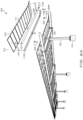
- Fig. 1 is a bottom perspective view of a dual-tilt mounting structure 100 with photovoltaic (PV) modules 114 mounted in portrait orientation 130 in accordance with various embodiments.
- Mounting structure 100 is installed over a mounting surface 102.
- a plurality of column foundations 104 extend from the mounting surface 102 (and in embodiments, extend below into mounting surface 102).
- a plurality of columns 106 are coupled to the column foundations 104.
- a plurality of crossbeams 108 are coupled to the columns 106.
- a plurality of purlins 110 are coupled to the crossbeams 108. In the embodiment shown in Fig. 1 , a first set of purlins 110 are coupled to a first end of crossbeams 108 on the left end of crossbeams 108.
- a second set of purlins 110 are coupled to a second, opposite end of crossbeams 108 on the right end of crossbeams 108.
- a first plurality of PV module support rails 112 are coupled to the purlins 110.
- a second plurality of PV module support rails 116 are coupled to the first plurality of PV module support rails 112.
- PV modules 114 are coupled to the PV module support rails 112, 116 in a first grid 120 and a second grid 122. PV module 114 are installed on dual-tilt mounting structure 100 in a portrait orientation 130.
- dual-tilt mounting structure 100 extends along three axes.
- a first axis (the z-axis shown in Figs. 1 and 2 ) extends upward from mounting surface 102.
- Column foundation 104 and columns 106 lay at least in part along the first axis.
- a second axis (the x-axis shown in Figs. 1 and 2 ) extends orthogonally from the second axis.
- Crossbeams 108 and PV module rails 112 lay at least in part along the second axis.
- a third axis (the y-axis shown in Figs. 1 and 2 ) extends orthogonally from the second and third axes.
- Purlins 110 lay at least in part along the third axis.
- Mounting surface 102 may be any of a number of surfaces onto which a mounting structure (e.g., mounting structure 100) is installed.
- mounting surface 102 is a parking lot on the ground or a top level of a parking garage.
- dual-tilt mounting structure 100 is configured to allow cars and trucks to be installed underneath dual-tilt mounting structure 100.
- dual-tilt mounting structure 100 may be referred to herein as a "carport.”
- dual-tilt mounting structure 100 (or any mounting structure discussed herein such as mounting structures 200, 320, 330, 340, 400, and 410) are not limited to embodiments in which the mounting structure is a carport installed over a parking lot.
- mounting surface 102 is a street or a sidewalk and the mounting surface is useable as cover for a pedestrian walkway, bus stop, or bike lane.
- mounting surface 102 may be a train platform and the mounting surface is usable as a cover for a train platform.
- column 106 is an I-beam, a square beam (shown in Fig. 1 ), or a tube or other suitable shape.
- column 106 is made of metal (such as stainless steel) or an electrically conductive composite material.
- column 106 includes a first flat plate on the bottom with openings configured to accept fasteners to couple the column 106 to a column foundation 104 (or mounting surface 102) and a second flat plate on the top with openings configured to accept fasteners to couple the column 106 to crossbeam 108.
- the top of column 106 is saddle-shaped and partially surrounds crossbeam 108. The coupling of column 106 to crossbeam 108 is discussed in additional detail in reference to Fig. 7A .
- Crossbeams 108 are coupled to the top ends of columns 106.
- crossbeams 108 are I-beams, although other suitable shapes may be used (e.g., a square beam).
- a first set of purlins 110 is coupled to first end of crossbeams 108 and a second set of purlins 110 is coupled to second end of crossbeams 108.
- crossbeam 108 is made of metal (such as stainless steel) or an electrically conductive composite material. The coupling of crossbeam 108 to purlins 110 is discussed in additional detail in reference to Fig. 7A .
- purlins 110 are coupled to crossbeams 108 at the lateral sides of crossbeams 108 as shown in Fig. 1 (e.g., fasteners 706 and brackets 704 as discussed in additional detail in reference to Fig. 7A ). In various other embodiments, however, purlins 110 could instead rest on top of crossbeams 108 and be coupled to the top of crossbeams 108 by fasteners that extend downward (i.e., along the first axis) through purlins 110 and into crossbeams 108. In various embodiments, purlins 110 are I-beams (as shown in Figs.
- purlins 110 may be T-beams or square beams.
- purlins 110 define a top flange upon which PV module support rails 112 lie and a bottom surface that faces mounting surface 102.
- bottom surface defines a flange (e.g., if purlin 110 is an I-beam).
- PV module support rails 112 are coupled to purlins 110 (e.g., by clamps 500 shown in Fig. 5A and 6A ). The coupling of purlins 110 to PV module support rails 112 is discussed in additional detail in reference to Figs. 5A , 6B , and 7A .
- a first set of PV module support rails 112 are coupled to purlins 110 and a second set of PV module support rails 116 are coupled to the first set of PV module support rails 112.
- the PV module support rails 112 and 116 are C-shaped beams that define a top surface, an opposing bottom surface, and a middle surface disposed between the top surface and the bottom surface.
- PV module support rails 112, 116 are made of metal (such as stainless steel) or an electrically conductive composite material. As discussed in further detail in reference to Figs.
- PV module support rails 112 rests on purlins 110.
- a clamp e.g., clamp 500 shown in Figs. 5A and 6A
- PV module support rails 116 have a similar (or identical) cross-section to PV module support rails 112, but instead of resting on purlins 110, PV module support rails 116 are coupled to PV module support rails 112 (e.g., by bracket 702 shown in Fig. 7A ) and are cantilevered over mounting surface 102.
- PV modules 114 are coupled to PV module support rails 112 and PV module support rails 116 (e.g., by fasteners 510 shown in Figs. 5A and 5B ).
- blocking rails 118 are coupled to the ends of PV module support rails 112, 116 to provide lateral support for PV module support rails 112, 116.
- PV module support rails 112 and in dual-tilt embodiments the PV module support rails 116) relative to the purlins 110 varies depending on the size of the PV modules 114 and the orientation (i.e., landscape orientation 202 shown in Fig. 2 versus portrait orientation 130). As discussed in further detail in reference to Figs. 5A and 6A , the spacing of PV module support rails 112, 116 relative to each other may differ according to the size and orientation of PV modules 114. In various embodiments in which PV modules 114 are installed in portrait orientation 130, PV module support rails 112, 116 face the same direction.
- pairs of PV module support rails 112, 116 may face each other (e.g., PV module support rails 112A and 112B shown in Fig. 6A ).
- blocking rails 118 are disposed between every PV module support rail 112, 116, but in other embodiments blocking rails are only disposed between opposing sets of PV module support rails 112, 116 (e.g., as shown in Fig. 6A ).
- PV modules 114 are disposed in portrait orientation 130 in a first grid 120 having columns extending along the second axis and rows extending along the third axis. As shown in additional detail in Figs. 5A and 5B , adjacent columns of PV modules 114 in first grid 120 share a PV module support rail 112 between them. Thus, if a first set of PV modules 114 are in a first column and second set of PV modules 114 are in an adjacent second column, they are secured to a top surface of a same PV module support rail 112 disposed between the first column and the second column.
- PV modules 114 in dual-tilt embodiments like dual-tilt mounting structure 100 are disposed in portrait orientation 130 in a second grid 122 having columns extending along the second axis and rows extending along the third axis.
- adjacent columns of PV modules 114 in second grid 122 share a PV module support rail 116 between them in the same fashion as first grid 120.
- the columns of first grid 120 and second grid 122 are aligned and the rows of the first grid and the second grid are parallel.
- first grid 120 and second grid 122 are disposed on planes that intersect.
- first grid 120 lies at between a 2- and 15-degree angle relative to mounting surface 102 and second grid 122 lies at between a -2- and -5-degree angle relative to mounting surface 102.
- PV modules 114 may be any of a number of rectangular-shaped PV modules.
- PV modules 114 are surrounded by frames made of metal (e.g., steel, aluminum, etc.), composite, or plastic.
- PV modules 114 are secured to PV module support rails 112 by fasteners that pass through the frames of PV modules 114 and PV module support rails 112 (e.g., as shown in Figs. 5A and 6A ) or by clamps that couple to the top side of PV modules 114 and are secured to PV module support rails 112.
- such frames are opaque.
- PV modules 114 are frameless (e.g., frameless bifacial PV modules) and are mounted to PV module support rails 112 by adhesives or clamps that couple to the top side of PV modules 114 and are secured to PV module support rails 112.
- PV modules 114 may be mounted in portrait orientation 130 (i.e., the long side of the PV module 114 is parallel to PV module support rails 112 and crossbeams 108) or in landscape orientation 202 (i.e., the long side of the PV module 114 is perpendicular to PV module support rails 112 as shown in Fig. 2 .
- PV modules 114 are monofacial modules with photovoltaic cells (e.g., monocrystalline silicon photovoltaic cells, polycrystalline silicon photovoltaic cells) arranged on an opaque backing sheet and surrounded by an encapsulant.
- the photovoltaic cells in a monofacial PV module 114 may be front-contact photovoltaic cells arranged individually or in a shingled arrangement in which adjacent photovoltaic cells overlap.
- photovoltaic cells in a monofacial PV module 114 may be interdigitated back contact photovoltaic cells.
- PV modules 114 are monofacial thin-film photovoltaic modules.
- PV modules 114 are bifacial modules with photovoltaic cells (e.g., monocrystalline silicon photovoltaic cells, polycrystalline silicon photovoltaic cells) arranged on a transparent backing sheet and surrounded by an encapsulant.
- the photovoltaic cells of a bifacial PV module 114 are configured to generate electricity that is received from the sun directly on the top surface of the PV module 114 that faces the sun and indirectly (i.e., reflected light, ambient light) on the bottom surface of the PV module that faces mounting surface 102.
- PV modules 114 are disposed in portrait orientation 130 with the long edges of the frames of PV modules 114 lying on top of PV module support rails 112 and 116.
- a bifacial PV module 114 was arranged in landscape orientation 202 (e.g., as shown in Fig. 2 and Fig. 6B for example) any light reflected from the mounting surface 102 onto the bottom surface of the PV module support rails 112 and 116 that intersect with the long edges of the frames of PV modules 114 would not reach the backside of the solar cells of the PV modules 114.
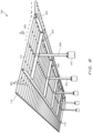
- Fig. 2 is a bottom perspective view of a dual-tilt mounting structure 200 with PV modules 114 mounted in landscape orientation 202 in accordance with various embodiments.
- the mounting surface 102, column foundations 104, columns 106, crossbeams 108, and purlins 110 are identical to those described above in reference to Fig. 1 .
- a dual-tilt mounting structure 200 may be reconfigured to become a dual-tilt mounting structure 100 shown in Fig. 1 by reconfiguring the arrangement of PV module support rails 112 and 116, blocking rails 118, and PV modules 114.
- the PV modules 114 installed on dual-tilt mounting structure 200 are installed in landscape orientation 202.
- PV modules 114 are monofacial PV modules. Accordingly, in various instances the monofacial PV modules 114 may be removed from dual-tilt mounting structure 200, the PV module support rails 112 and 116 and blocking rails 118 repositioned, and bifacial PV modules 114 installed in portrait orientation 130. Accordingly, the same column foundations 104, columns 106, crossbeams 108, purlins 110, PV module support rails 112 and 116, blocking rails 118, and PV modules 114 are usable to construct a dual-tilt mounting structure 200 with PV modules 114 mounted in landscape orientation 202 or a dual-tilt mounting structure 100 with PV modules 114 mounted in portrait orientation 130.
- the same PV module support rails 112 and 116 and blocking rails 118 may be used to construct dual-tilt mounting structure 200.
- pairs of PV module support rails 112 and 116 may face each other.
- blocking rails 118 may be installed between pair of facing PV module support rails 112 and 116 and not between PV module support rails 112 and 116 that face away from each other. This configuration can be seen more clearly in Fig. 6A below.
- the long sides of the frames of PV modules 114 are perpendicular to PV module support rails 112 and 116.
- first grid 120 and second grid 122 of Fig. 1 the landscape-oriented PV module 114 in Fig. 2 are arranged in a first grid 204 and a second grid 206 in which columns for first grid 204 are aligned with columns of second grid 206 and first grid 204 and second grid 206 define planes that intersect.
- landscape orientation 202 results in shadows being cast on the backside of the PV modules 114, but if the PV modules 114 are monofacial, this will not affect power generation. Moreover, depending on the shading conditions at a particular site (e.g., due to trees or tall buildings) a landscape orientation 202 may result in more power generation than portrait orientation 130, even for bifacial PV modules 114. Accordingly, the mounting structures described herein allow for flexibility in both design and construction of the mounting structure without having to use different sets of parts.
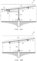
- a side view of a dual-tilt mounting structure 100 is shown (although in various embodiments a side view of dual-tilt mounting structure 200 would also look like Fig. 3A ).
- Fig. 3A identifies various water management features.
- a gutter 302 is disposed beneath the junction of PV module support rails 112 and 116 and collects water that flows across first grid 120 and second grid 122. Gutter 302 drains through pipe 304 and into a downspout 306 in column 106.
- downspout 306 discharges water onto mounting surface 102 or into a cistern installed on mounting surface 102 (not shown), but in other embodiments, downspout 306 drains to pipes beneath mounting surface 102 (e.g., to a drainage system of a parking garage, to a rainwater sewer, to an underground cistern).
- column foundation 104 is partially cut away, showing fasteners 310 that are buried in column foundation 104 and are received by corresponding openings on a flat bottom portion of column 106. Nuts are used to secure column 106 to fasteners 310 in various embodiments.
- Fig. 3A also includes various dimensions A-E. As shown in Fig. 3A , the longest dimension is D, the span of the top of mounting structure 100. In various embodiments, D is 41 feet, 10 inches (approximately 12.75 meters). Dimension E, the extent to which column foundations 104 extend above mounting surface 102 is between 2.5 feet (approximately 0.76 meters) and 4 feet (approximately 1.22 meters). Dimensions B and C are based on Dimension A, which is the minimum clearance under mounting structure 100. In some embodiments, Dimension A is 11 feet (approximately 3.35 meter) and Dimension B is 14 feet, 4 inches (approximately 4.37 meters) and Dimension C is 18 feet, 5 inches (approximately 5.61 meters).
- Dimension A is 13 feet, 6 inches (approximately 4.11 meters) and Dimension B is 16 feet, 10 inches (approximately 5.13 meters) and Dimension C is 20 feet, 11 inches (approximately 6.38 meters). It will be understood, however, that these Dimensions A-E may vary from these numbers (e.g., by 5%, 10%, etc.) and may be changed based on customer requirements (e.g., Dimension A defines a higher minimum clearance for larger vehicles). Further, the mounting structure 100 shown in Fig. 3A is a carport, and the Dimensions A-E may be reduced for applications requiring shorter spans and/or smaller minimum clearances.
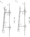
- a single-tilt mounting structure 320 is shown.
- the single-tilt mounting structure 320 no PV module support rails 116 are present, and PV module support rails 112 are longer. Additionally, the water management features of Fig. 3A are not present.
- PV modules 114 are arranged in a single grid 322.
- Fig. 3B also includes various dimensions A-E. As shown in Fig. 3B , the longest dimension is D, the span of the top of mounting structure 320. In various embodiments, D is 41 feet, 9 inches (approximately 12.72 meters).
- Dimension E the extent to which column foundations 104 extend above mounting surface 102 is between 2.5 feet (approximately 0.76 meters) and 4 feet (approximately 1.22 meters).
- Dimensions B and C are based on Dimension A, which is the minimum clearance under mounting structure 100. In some embodiments, Dimension A is 11 feet (approximately 3.35 meter) and Dimension B is 12 feet, 4 inches (approximately 3.76 meters) and Dimension C is 17 feet, 8 inches (approximately 5.38 meters). In other embodiments, Dimension A is 13 feet, 6 inches (approximately 4.11 meters) and Dimension B is 14 feet, 10 inches (approximately 4.52 meters) and Dimension C is 20 feet, 2 inches (approximately 6.15 meters).
- a shorter span dual-tilt mounting structure 330 is shown.
- Dimension D' is shorter than Dimension D in Fig. 3A and Dimension C' is shorter than Dimension C in Fig. 3A .
- the crossbeam 332 is shorter than crossbeam 108.
- a shorter span single-tilt mounting structure 340 is shown.
- Dimension D' is shorter than Dimension D in Fig. 3B
- Dimension C' is shorter than Dimension C in Fig. 3B
- the crossbeam 332 is shorter than crossbeam 108.
- PV module support rails 112 are shorter as well.
- crossbeams 402 may be longer than crossbeams 108 and are connected to two sets of column foundations 104 and columns 106 and PV module support rails 112 may be longer.
- crossbeams 402 and PV module support rails 112 in long span mounting structures may be comprised of multiple crossbeams 402 or PV module support rails 112 that are coupled together end-to-end.
- Figs. 5A-5C relate to embodiments in which PV modules 224 are mounted in portrait orientation 130.
- Fig. 5D relates to reflected light and relates to bifacial PV modules, which are mounted in portrait orientation 130 in some embodiments, but may be mounted in landscape orientation 202 as well.
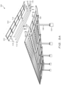
- Fig. 5A a bottom perspective partially exploded view of the dual-tilt mounting structure 100 with PV modules 114 mounted in portrait orientation 130 is shown.
- the mounting of PV modules 114 in portrait orientation 130 is not limited to mounting structure 100 and can be used on the single-tilt, shorter span, and/or longer span embodiments discussed above.
- a set of PV module support rails 112 and 116, PV modules 114, and blocking rails 118 are exploded of off purlins 110.
- Clamps 500 and fasteners 510 and 512 are also shown.
- clamps 500 are used to secure PV module support rails 112 to purlins 110
- fasteners 510 are used to secure PV modules 114 to PV module support rails 112 and 116
- fasteners are used to secure blocking rails 118 to PV modules 114.
- PV module support rails 112 and 116 are C beams in various embodiments. As shown in Fig. 5A , a lateral side of the C beam faces the viewer and the open side of the C beam faces away from the viewer. PV module support rails 112 and 116 include a bottom surface that is coupled to purlins 110. The top surface of PV module support rails 112 and 116 define a plurality of openings configured to accept fasteners 510 to secure PV modules 114 to PV module support rails 112 and 116. As shown in Fig. 5A , fasteners 510 pass through the long side of the frames of PV modules 114.
- fasteners 510 include components that establish an electrical grounding path between PV modules 114 and PV module support rails 112 and 116. Such components may include grounding washers that breach coatings (e.g., paint, reflective coatings 532 discussed in connection to Fig. 5D ) to enable the grounding path to be established. Similarly, fasteners 512 may also include similar components that establish and electrical grounding path between PV modules 114 and blocking rails 118.
- clamps 500 couple PV module support rails 112 to purlins 110.
- clamps 500 include a top portion 502 and one or more bottom portions 504.
- top portions 502 are fastened to PV module support rails 112 and bottom portions 504 are coupled to purlins 110.
- clamps 500 are not secured to purlins 110 by fasteners that pass through purlins 110 or by welding.
- the top flange of purlins 110 do not define any openings at all.
- clamps 500 pinch a top flange of purlin 110 and are held by tension on fasteners that pass through top portions 502 and bottom portions 504. In such embodiments, the structural integrity of purlins 110 is not diminished by openings. Similarly, because clamps 500 attach PV module support rails 112 to purlins 110 by pinching the top flange and without fasteners having to pass through purlins 110, there is greater flexibility on where PV module support rails 112 can be attached. This allows for the variable spacing of PV module support rails 112 that is used for portrait orientation 130 mounting and landscape orientation 202 mounting without having to modify purlins 110.
- fasteners 510 includes components that establish an electrical grounding path between PV modules 114 and PV module support rails 112A, 112B and 116A,116B. Such components may include grounding washers that breach coatings (e.g., paint, reflective coatings 532 discussed in connection to Fig. 5D ) to enable the grounding path to be established. Similarly, fasteners 512 may also include similar components that establish and electrical grounding path between PV modules 114 and blocking rails 118.
- clamps 500 attach PV module support rails 112A, 112B to purlins 110 without fasteners passing though purlins 110 or by weld points. Accordingly, an entire box of blocking rails 118, PV module support rails 112A and 116B, and PV module support rails 112B and 116B may be assembled on the ground, and PV modules 114 secured to PV module support rails 112A, 112B and 116A, 116B. Then, the entire subassembly may be lifted onto mounting structure 200 and secured with clamps 500. To remove and replace the PV modules, this operation would just need to be done in reverse.
- Fig. 6B is a top view of a set of PV modules 114 mounted in landscape orientation 202 on a set of PV module support rails 112A, 112B, 116A, 116B in accordance with various embodiments.
- purlins 110, PV module support rails 112A, 112B, 116A, and 116B, and gutter 302 are shown in dashed lines because they are obscured by PV modules 114.
- a wire tray 600 is shown in dashed lines.
- Various embodiments of mounting structure 100, 200, etc. have wire trays 600 that are configured to support electrical wires connected to the PV modules 114 in various embodiments. As shown in Fig.
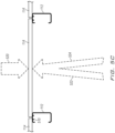
- Fig. 6C is a cutaway side view of two monofacial PV modules 114 mounted in landscape orientation 202 on a set of PV module support rails 112A and 112B in accordance with various embodiments.
- only direct light 520 is shown because the monofacial PV modules 114 only generate electricity on the top side.
- Brackets 704 are L-shaped brackets that are configured to receive a plurality of fasteners 706 on both sides of the L. While four fasteners 706 are shown in Fig. 7A , more or fewer fasteners could be used in various embodiments. In some embodiments, fasteners 706 pass though brackets 704 and into corresponding female threaded components embedded in crossbeam 108 and/or purlin 110.
- holes are drilled through crossbeam 108 and/or purlin 110 (either during manufacture or in the field) and fasteners are secured using nuts on the other side of crossbeam 108 and/or purlin 110.
- fasteners 706 are male threaded screws or bolts.
- purlins 110 are coupled to side surfaces of the crossbeams 108 (i.e., as opposed to resting on top of the crossbeams 108 and being coupled to top flange 712).
- crossbeam 108 includes a top flange 712 with helps support the weight of PV module support rails 112 and PV modules 114, provides an attachment surface for clamp 500, and provides lateral support along the length of crossbeam 108.
- crossbeam 108 defines a cutout 718 that is useable to run wires (e.g., wires for lighting installed in mounting structure 100, wires connected to PV modules 114) through mounting structure.
- crossbeam 108 is coped (e.g., has a notch) such that the middle portion of the crossbeam has clearance to fit in a smaller middle section of purlin 110.
- Purlins 110 are coupled to the PV module support rails 112 by clamps 500 that couple to top flange 740 of purlins 110 as discussed previously and in further detail in reference to Figs. 9A-9H .
- Purlins 110 define a weight-reduction cutout 742 at the ends of purlins 110 in various embodiments.
- PV module support rails 112 and 116 are C beams.
- PV module support rails 112 and 116 define a top surface 720, an intermediate surface 722, and a bottom surface 724.
- top surface 720 define a series of holes (e.g., threaded holes, round and slotted punches) that are configured to receive fasteners 510.
- such holes are formed during manufacturing, and the top surface 720 of PV module support rails 112 and 116 includes holes usable to accept fasteners 510 to couple PV modules 114 in portrait orientation 130 or landscape orientation 202 (i.e., top surface 720 defines sets of holes for both orientations and only one set is used).
- Intermediate surface 722 also defines sets of holes configured to accept fasteners (e.g., fasteners 940 shown in Fig. 9C ) to couple top portion 502 of clamp 500 to the intermediate surface 722.
- Bottom surface 724 is configured to lie on top flange 740 when PV module support rails 112 are installed.
- PV module support rails 112 and 116 define holes 728 that are configured to receive fasteners that pass through bracket 702 to secure PV module support rails 116 to PV module support rails 112.
- bracket 702 defines four holes: the top two holes are configured to receive fasteners that are received by holes 728 and the bottom two holes are configured to receive fasteners to secure gutter 302 (not shown in Fig. 7A ) to bracket 702.
- Blocking rails 118 define a pair of holes 730 that are configured to receive fasteners that pass through PV module support rails 112 and 116 and into holes 730 to secure blocking rails 118 between pairs of PV module support rails 112 and 116.
- electrical grounding is facilitated by self-adhesive grounding patches 700 that are disposed between various structural support components.
- a self-adhesive grounding patch 700 is disposed between column 106 and crossbeam 108, and when fasteners 708 are tightened, the self-adhesive grounding patch 700 breaks through coatings (e.g., paint, anodization, or oxidation) on column 106 and crossbeam 108 and establishes an electrical grounding path.
- self-adhesive grounding patches 700 are disposed between crossbeams 108 and purlins 110 such that when crossbeams 108 and purlins 110 are coupled using bracket 704 and fasteners 706, self-adhesive grounding patches 700 breaks through coatings (e.g., paint, anodization, or oxidation) on crossbeam 108 and purlins 110 and establishes an electrical grounding path.
- coatings e.g., paint, anodization, or oxidation
- self-adhesive grounding patches 700 are disposed between top portion 502 of clamp 500 and PV module support rails 112 such that self-adhesive grounding patches 700 breaks through coatings (e.g., paint, anodization, or oxidation) on PV module support rails 112 and clamp 500 and establishes an electrical grounding path.
- coatings e.g., paint, anodization, or oxidation
- bottom portion 504 is able to establish a grounding path between clamp 500 and purlin 110.
- another set of self-adhesive grounding patches 700 are disposed between bottom portion 504 and purlin 110 to establish the grounding path.
- self-adhesive grounding patches 700 are disposed between brackets 702 and PV module support rails 112 and/or 116. Accordingly, though the use of PV module support rails 112 and/or clamps 500, an electrical grounding path can be established between columns 106, crossbeams 108, purlins 110, and PV module support rails 112 and 116 as the structural support components are installed from the ground up. This may allow mounting structures as described herein to be grounded as it is being assembled and not after the PV modules 114 have been installed. This approach may reduce the risk of electrical shocks prior to grounding paths being established and allow non-electricians to establish the grounding path, which may subsequently be approved by electricians at lower labor cost.
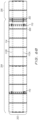
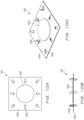
- Fig. 7B is a top view of the dual-tilt mounting structure 100 with the PV modules 114 omitted.
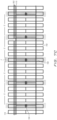
- Fig. 7C is a top view of the dual-tilt mounting structure 200 with the PV modules 114 omitted.
- column foundation 104 and columns 106 may be installed at the mounting surface 102 in a range labeled G. In various embodiments, this range can be about 3 feet (approximate .91 meters), with the column foundation 104 and columns 106 able to be installed anywhere within that 3-foot range.
- column foundation 104 and columns 106 are separated by range F, which may range up to 36 feet (approximately 10.97 meters) in various embodiments.
- range F may range up to 36 feet (approximately 10.97 meters) in various embodiments.
- a first column foundation 104 and first column 106 may be 36 feet from a second column foundation 104 and second column 106, but a third column foundation 104 and third column 106 are only 34 feet from the second column foundation 104 and second column 106.
- column foundation 104 and columns 106 may be irregularly spaced apart on mounting surface 102 to, for example, work around unexpected site conditions that were not known prior to installation. Additionally, referring to Fig.
- gaps 750 can be seen showing places in which blocking rails 118 are not installed between boxes of blocking rails 118, PV module support rails 112A and 116B, and PV module support rails 112B and 116B discussed previously. It will be understood that while Figs. 7B and 7C show five crossbeams 108, mounting structures constructed according to the techniques described herein may be longer (i.e., having more crossbeams 108) or shorter (i.e., having fewer crossbeams).
- Fig. 8 is a bottom perspective view of dual-tilt mounting structure 100 with various water management features highlighted in accordance with various embodiments.
- gaskets 800 are disposed between PV modules 114 that are installed in either landscape orientation 202 or portrait orientation 130. This causes water 802 to flow down the angled top surface of mounting structure 100 and into gutter 302. From gutter 302, water is able to flow through pipe 304 and into downspout 306.
- mounting structure 100 (and other dual-tilt mounting structure described herein) are able to shelter people and objects underneath from precipitation and move water away.
- mounting structure 100 may have integrated heating elements (e.g., heating elements in PV module support rails 112 and 116) that prevent snow and ice from accumulating on PV modules 114.
- Fig. 9A is a perspective view of a top portion 502 and a bottom portion 504 of the clamp 500 shown in of Figs. 5A , 6A , and 7A in accordance with various embodiments.
- Top portion 502 is an L-shaped bracket having a first top plate 900 that defines a pair of holes 904 and a second top plate 902 defines a pair of holes 906.
- first top plate 900 is configured to be adjacent to intermediate surface 722 of PV module support rails 112 and second top plate 902 is configured to lie on top flange 712 of purlin 110.
- first top plate 900 is configured to be adjacent to intermediate surface 722 of PV module support rails 112 and second top plate 902 is configured to lie on top flange 712 of purlin 110.
- bottom portion 504 is a clamping jaw that defines a first portion 910 defining a rounded first top surface 912, a second portion 914 defining a flat second top surface 915 with a hole 916 configured to receive a clamping fastener 950, and a third portion 918 defining a rounded third top surface 920.
- the rounded first top surface 912 abuts top portion 502 and rounded third top surface 920 abuts the underside of the top flange 740 of purlin 110.
- the rounded first top surface 912 is configured to breach one or more coatings on purlin 110 and establish a grounding path between clamp 500 and purlin 119.
- FIG. 9B a perspective view of a top portion 502 and an alternate bottom portion 504A of an alternative clamp 500A is shown.
- Alternative bottom portion 504A is S-shaped with a first portion 932 defining a hole 936 configured to receive clamping fastener 950 and a second portion 924.
- first portion 932 abuts top portion 502
- second portion 934 abuts the underside of the top flange 740 of purlin 110.
- a self-adhesive grounding patch 700 may be inserted between second portion 934 and the underside of top flange 740 of purlin 110.
- a self-adhesive grounding patch 700 may be inserted between second top plate 902 of top portion 502 and the top surface of top flange 740.
- FIGs. 9C-9H various views of an installed clamp 500 are shown.
- Figs. 9C , 9E, and 9G are various views of clamp 500 installed with the top portion 502 secured to an outer surface of a PV support module support rail 112.
- Figs. 9D , 9F, and 9H are various views of clamp 500 installed with the top portion 502 secured to an inner surface of a PV support module support rail 112.
- PV support module support rail 112 are able to be secured to the mounting structure without welding and without having to pass fasteners through purlins 110.
- FIG. 9C a side view of clamp 500 installed on a mounting structure is shown.
- clamp 500 is installed with first top plate 900 secured to an outer surface of a PV support module support rail 112 by a pair of fasteners 940 (e.g., bolts) that extend through holes 905 and are secured by bolts 942 (see Fig. 9E ).
- Second top plate 902 is secured to the top of top flange 740 of purlin 110.
- Two bottom portions 504 are disposed on the bottom side of top flange 740.
- Clamping fasteners 950 e.g., a bolt
- Fig. 9E is a cutaway side view showing clamp 500 installed on a mounting structure as described in reference to Fig. 9C .
- Fig. 9G is a bottom perspective view showing clamp 500 installed on a mounting structure as described in reference to Fig. 9C .
- bottom portions 504 are disposed between the PV module support rail 112 and the end of purlin 110 at a distance H from the end of purlin 110.
- FIG. 9D a side view of clamp 500 installed on a mounting structure in an alternative manner is shown.
- clamp 500 is installed with first top plate 900 secured to an inner surface of a PV support module support rail 112 by a pair of fasteners 940 (e.g., bolts) that extend through holes 905 and are secured by bolts 942 (see Fig. 9F ).
- top portion 502 is disposed inside PV support module support rail 112 in some embodiments.
- Second top plate 902 is secured to the inside of bottom surface 724 of PV support module support rail 112.
- plate 1000 is made of metal (e.g., stainless steel) and is a square with sides between 1 (approximately 2.54 centimeters) and 5 inches (approximately 12.7 centimeters) long.
- adhesive pad 1002 is a peel and stick adhesive that is attached to plate 1000 during manufacture with a peelable top sheet that is removed prior to installation as discussed herein. Cutouts 1004 are arranged around adhesive pad 1002 and are bent above and below to form spikes 1006. In various embodiments, eight cutouts 1004 and spikes 1006 are present and are arranged on the sides and corners of plate 1000 as shown in Figs. 10A-10 , but other arrangements can be used (e.g., more cutouts and spikes may be present).
Landscapes
- Engineering & Computer Science (AREA)
- Architecture (AREA)
- Physics & Mathematics (AREA)
- Life Sciences & Earth Sciences (AREA)
- Sustainable Energy (AREA)
- Mechanical Engineering (AREA)
- Chemical & Material Sciences (AREA)
- Combustion & Propulsion (AREA)
- Thermal Sciences (AREA)
- General Engineering & Computer Science (AREA)
- Sustainable Development (AREA)
- Civil Engineering (AREA)
- Structural Engineering (AREA)
- Electromagnetism (AREA)
- Photovoltaic Devices (AREA)
- Roof Covering Using Slabs Or Stiff Sheets (AREA)
Claims (15)
- System (100), aufweisend:eine Vielzahl von Säulen (106), die sich von einer Montagefläche (102) aus entlang einer ersten Achse erstrecken, wobei obere Enden der Vielzahl von Säulen (106) über der Montagefläche (102) angeordnet sind;eine Vielzahl von Querträgern (108), die mit den oberen Enden der Vielzahl von Säulen (106) verbunden sind und sich entlang einer zweiten Achse erstrecken, wobei einzelne Querträger (108) ein erstes Ende und ein entgegengesetztes zweites Ende umfassen;eine Vielzahl von Pfetten (110), die mit der Vielzahl von Querträgern (108) verbunden sind und sich entlang einer dritten Achse erstrecken, wobei ein erster Satz von Pfetten (110) mit den ersten Enden der Vielzahl von Querträgern (108) und ein zweiter Satz von Pfetten (110) mit den zweiten Enden der Vielzahl von Querträgern (108) verbunden sind;eine erste Vielzahl von Stützschienen (112) für ein photovoltaisches (PV) Modul, die sich entlang der zweiten Achse über die Vielzahl von Pfetten (110) hinweg erstrecken, wobei einzelne PV-Modul-Stützschienen (112) eine Unterseite, die mit der Vielzahl von Pfetten verbunden ist, und eine Oberseite aufweisen, die eine Vielzahl von Öffnungen definiert, die dafür ausgelegt sind, Befestigungselemente (510) aufzunehmen; undeine Vielzahl von rechteckigen PV-Modulen (114), die an den Oberseiten der ersten Vielzahl von PV-Modul-Stützschienen (112) durch Befestigungselemente (510) befestigt sind, die sich durch die rechteckigen PV-Module (114) und die Öffnungen erstrecken, die zur Aufnahme der Befestigungselemente (510) ausgelegt sind;wobei die Vielzahl von rechteckigen PV-Modulen (114) in Hochformat-Ausrichtung (130) in einem ersten Gitter mit Spalten, die sich entlang der zweiten Achse erstrecken, und Reihen, die sich entlang der dritten Achse erstrecken, angeordnet sind; undwobei ein erster Satz von rechteckigen PV-Modulen (114) in einer ersten Spalte und ein zweiter Satz von rechteckigen PV-Modulen (114) in einer benachbarten zweiten Spalte an einer Oberseite derselben PV-Modul-Stützschiene (112, 116) befestigt sind, die zwischen der ersten Spalte und zweiten Spalte angeordnet ist.
- System (100) nach Anspruch 1, wobei die Säulen (106), die Querträger (108), die Pfetten (110) und die PV-Modul-Stützschienen (112, 116) mit einer reflektierenden Beschichtung (530, 532) beschichtet sind.
- System (100) nach Anspruch 1, wobei ein Abschnitt der Montagefläche (102) mit einer reflektierenden Beschichtung (530, 532) beschichtet ist, die dafür ausgelegt ist, Licht zu den rechteckigen PV-Modulen (114) zu reflektieren.
- System (100) nach Anspruch 1, wobei die rechteckigen PV-Module (114) doppelseitige PV-Module sind.
- System (100) nach Anspruch 1,wobei das erste Gitter eine erste Ebene definiert;wobei das System (100) darüber hinaus aufweist:eine zweite Vielzahl von PV-Modul-Stützschienen (116), die mit der ersten Vielzahl von PV-Modul-Stützschienen (112) verbunden sind und sich entlang der zweiten Achse erstrecken; undeine zweite Vielzahl von rechteckigen PV-Modulen (114), die an Oberseiten der zweiten Vielzahl von PV-Modul-Stützschienen (116) befestigt sind;wobei die zweite Vielzahl von rechteckigen PV-Modulen (114) in einer Hochformat-Ausrichtung (130) in einem zweiten Gitter mit Spalten, die sich entlang der zweiten Achse erstrecken, und Reihen, die sich entlang der dritten Achse erstrecken, angeordnet sind, wobei die Spalten des ersten Gitters und zweiten Gitters ausgerichtet sind und die Reihen des ersten Gitters und zweiten Gitters parallel sind; undwobei das zweite Gitter eine zweite Ebene definiert, die sich mit der ersten Ebene schneidet.
- System (100) nach Anspruch 1,wobei eine Vielzahl von selbstklebenden Erdungsauflagen (700) zwischen verbundenen Säulen (106) und Querträgern (108) und zwischen verbundenen Querträgern (108) und Pfetten (110) angeordnet sind; undwobei ein elektrischer Erdungspfad zwischen der Säule (106), dem Querträger (108) und der Vielzahl von Pfetten (110) hergestellt ist.
- System (100) nach Anspruch 1, wobei die erste Vielzahl von PV-Modul-Stützschienen (112) an der Vielzahl von Pfetten (110) durch jeweilige Klammern (500) befestigt sind, wobei die Klammern (500) umfassen:einen L-förmigen Bügel mit einem ersten Abschnitt (502), der an einer bestimmten PV-Modul-Stützschiene (112) durch ein oder mehrere Bügelbefestigungselemente befestigt ist, und einem zweiten Abschnitt (504), der mit einer bestimmten Pfette (110) verbunden ist,eine oder mehrere Klemmbacken, die mit einem bestimmten oberen Flansch der bestimmten Pfette (110) verbunden sind; undeine Klemmbefestigung, die sich durch den zweiten Abschnitt (504) und die Klemmbacke erstreckt, wobei durch eine Zugspannung an der Klemmbefestigung der zweite Abschnitt des L-förmigen Bügels und die Klemmbacke an der bestimmten Pfette (110) befestigt werden.
- System (100) nach Anspruch 7, darüber hinaus aufweisend:einen ersten Satz von selbstklebenden Erdungsauflagen (700), die zwischen dem L-förmigen Bügel und den bestimmten PV-Modul-Stützschienen (112) angeordnet sind; undeinen zweiten Satz von selbstklebenden Erdungsauflagen (700), die zwischen der Klemmbacke und der bestimmten Pfette (110) angeordnet sind;wobei ein elektrischer Erdungspfad zwischen der bestimmten PV-Modul-Stützschiene (112) und der bestimmten Pfette (110) hergestellt ist.
- System (100) nach Anspruch 1, wobei die Pfetten (110) mit Seitenflächen des ersten und zweiten Endes der Querträger (108) verbunden sind.
- Solar-Carport, aufweisend das System (100) nach einem der Ansprüche 1-9.
- Solar-Carport nach Anspruch 10, wobei ein elektrischer Erdungspfad in dem Solar-Carport zumindest zum Teil durch eine Vielzahl von selbstklebenden Erdungsauflagen (700) hergestellt ist, die zwischen Komponenten des Solar-Carports angeordnet sind.
- Verfahren, umfassend:Einsetzen einer Vielzahl von Säulenfundamenten (104) an einer Montagefläche (102), wobei die Säulenfundamente (104) teilweise in die Montagefläche (102) eingebettet sind und sich oberhalb der Montagefläche (102) erstrecken;Verbinden einer Vielzahl von Säulen (106) mit den Säulenfundamenten (104);Verbinden einer Vielzahl von Querträgern (108) mit der Vielzahl von Säulen (106), wobei ein bestimmter Querträger (108) mit einer bestimmten Säule (106) verbunden ist;Verbinden einer Vielzahl von Pfetten (110) mit der Vielzahl von Querträgern (108), wobei ein erster Satz von Pfetten (110) mit ersten Enden der Vielzahl von Querträgern (108) und ein zweiter Satz von Pfetten (110) mit zweiten Enden der Vielzahl von Querträgern (108) verbunden sind;Verbinden einer Vielzahl von Stützschienen (112, 116) für ein photovoltaisches (PV) Modul mit der Vielzahl von Pfetten (110), wobei die Vielzahl von PV-Modul-Stützschienen (112, 116) eine erste PV-Modul-Stützschiene (112), eine zweite PV-Modul-Stützschiene (116) und eine dritte PV-Modul-Stützschiene (112) umfasst, wobei die zweite PV-Modul-Stützschiene (116) zwischen der ersten PV-Modul-Stützschiene (112) und der dritten PV-Modul-Stützschiene (112) angeordnet ist;Verbinden eines ersten Satzes von rechteckigen PV-Modulen (114) mit der ersten PV-Modul-Stützschiene (112) und der zweiten PV-Modul-Stützschiene (116), wobei der erste Satz von rechteckigen PV-Modulen (114) eine Hochformat-Ausrichtung (130) hat; undVerbinden eines zweiten Satzes von rechteckigen PV-Modulen (114) mit der zweiten PV-Modul-Stützschiene (116) und der dritten PV-Modul-Stützschiene (112), wobei der zweite Satz von rechteckigen PV-Modulen (114) eine Hochformat-Ausrichtung (130) hat,wobei einzelne PV-Modul-Stützschienen (112, 116) eine Oberseite umfassen, die eine Vielzahl von Öffnungen definieren, die dafür ausgelegt sind, Befestigungselemente (510) aufzunehmen, um PV-Module (114) an den PV-Modul-Stützschienen (112, 116) über die Befestigungselemente (510) zu befestigen, die sich durch die PV-Module (114) und die Öffnungen erstrecken.
- Verfahren nach Anspruch 12, wobei das Verbinden der Vielzahl von PV-Modul-Stützschienen (112) mit der Vielzahl von Pfetten (110) die Verwendung einer Vielzahl von Klammern (500) umfasst, um die PV-Modul-Stützschienen (112) an der Vielzahl von Pfetten (110) zu befestigen, und weder das Einsetzen von Befestigungselementen durch die Pfetten (110) noch einen Schweißvorgang umfasst.
- Verfahren nach Anspruch 12, darüber hinaus umfassend:
Aufbringen einer reflektierenden Beschichtung (530, 532) auf mindestens 95% der Montagefläche (102) unter dem ersten und zweiten Satz von rechteckigen PV-Modulen (114). - Verfahren nach Anspruch 12,wobei das Verbinden der Vielzahl von Querträgern (108) mit der Vielzahl von Säulen (106) das Einsetzen von selbstklebenden Erdungsauflagen (700) zwischen der Vielzahl von Querträgern (108) und der Vielzahl von Säulen (106) umfasst; undwobei das Verbinden der Vielzahl von Pfetten (110) mit der Vielzahl von Querträgern (108) das Einsetzen von selbstklebenden Erdungsauflagen (700) zwischen der Vielzahl von Pfetten (110) und der Vielzahl von Querträgern (108) umfasst,wobei das Verfahren darüber hinaus umfasst:
Überprüfen, dass ein elektrischer Erdungspfad zwischen der Vielzahl von Säulen (106), der Vielzahl von Querträgern (108) und der Vielzahl von Pfetten (110) hergestellt ist.
Applications Claiming Priority (2)
| Application Number | Priority Date | Filing Date | Title |
|---|---|---|---|
| US202063068017P | 2020-08-20 | 2020-08-20 | |
| PCT/US2021/046650 WO2022040404A1 (en) | 2020-08-20 | 2021-08-19 | Photovoltaic module mounting structure |
Publications (3)
| Publication Number | Publication Date |
|---|---|
| EP4200973A1 EP4200973A1 (de) | 2023-06-28 |
| EP4200973C0 EP4200973C0 (de) | 2025-05-21 |
| EP4200973B1 true EP4200973B1 (de) | 2025-05-21 |
Family
ID=77739137
Family Applications (1)
| Application Number | Title | Priority Date | Filing Date |
|---|---|---|---|
| EP21769848.9A Active EP4200973B1 (de) | 2020-08-20 | 2021-08-19 | Montagestruktur für fotovoltaisches modul |
Country Status (3)
| Country | Link |
|---|---|
| US (2) | US11689147B2 (de) |
| EP (1) | EP4200973B1 (de) |
| WO (1) | WO2022040404A1 (de) |
Families Citing this family (9)
| Publication number | Priority date | Publication date | Assignee | Title |
|---|---|---|---|---|
| IT201900008322A1 (it) * | 2019-06-07 | 2020-12-07 | Axet S R L | Struttura dinamica di supporto per pannelli solari |
| USD994143S1 (en) * | 2020-09-21 | 2023-08-01 | Visual Graphic Systens Inc. | Drive thru structure |
| US12003212B2 (en) * | 2021-12-29 | 2024-06-04 | Lawrence Kearns | Self-ballasted pre-engineered modular platform assembled onsite for generating electricity with bifacial photovoltaic modules |
| US12323088B1 (en) * | 2022-07-14 | 2025-06-03 | Gary D. Craddock | Solar panel support |
| EP4343226A1 (de) * | 2022-09-23 | 2024-03-27 | Thomas Bockmeyer | Solarpaneel und zaun, ausgestattet mit mindestens einem derartigen solarpaneel |
| FR3149959B1 (fr) * | 2023-06-14 | 2025-10-03 | Closura | Système de fixation de panneau solaire sur un toit, et structure ou abri portant au moins un panneau solaire sur son toit fixé via ledit système |
| JP7539745B1 (ja) * | 2024-01-05 | 2024-08-26 | 株式会社 Fd | カーポート |
| PL448043A1 (pl) * | 2024-03-19 | 2025-09-22 | Przedsiębiorstwo Robót Drogowych Lubartów Spółka Akcyjna | Wspornik do konstrukcji wiaty |
| USD1050490S1 (en) * | 2024-06-06 | 2024-11-05 | Linhai Tianchen Leisure Products Co., Ltd. | Carport |
Family Cites Families (34)
| Publication number | Priority date | Publication date | Assignee | Title |
|---|---|---|---|---|
| US2250280A (en) * | 1940-05-14 | 1941-07-22 | Maurice M Starbird | Electrical bond |
| US2720290A (en) * | 1951-06-05 | 1955-10-11 | Kaiser Aluminium Chem Corp | Clamp assembly for structural elements |
| US4023882A (en) * | 1974-04-25 | 1977-05-17 | Borge Hugo Pettersson | Electrical connector device securable to metal member |
| US8092129B2 (en) * | 2006-04-21 | 2012-01-10 | Hubbell Incorporated | Bonding washer |
| WO2008118518A1 (en) * | 2007-03-23 | 2008-10-02 | Sunpower Corporation | Stackable tracking solar collector assembly |
| US8109048B2 (en) | 2008-02-11 | 2012-02-07 | Zap Solar, Inc. | Apparatus for forming and mounting a photovoltaic array |
| US8832938B2 (en) | 2008-03-27 | 2014-09-16 | Panelclaw, Inc. | Ground mounted solar module integration system |
| AU2009266857A1 (en) * | 2008-07-02 | 2010-01-07 | Laurence Mackler | Solar power generation display assembly and method for providing same |
| US11063553B2 (en) * | 2008-11-17 | 2021-07-13 | Kbfx Llc | Solar carports, solar-tracking carports, and methods |
| US20100275975A1 (en) * | 2009-04-30 | 2010-11-04 | Jonathan Monschke | Solar panel systems |
| KR101409681B1 (ko) | 2009-06-05 | 2014-06-19 | 퍼스트 솔라, 인코포레이티드 | 태양전지 모듈 지반 탑재 시스템 |
| US20100132769A1 (en) * | 2009-10-23 | 2010-06-03 | Chevron U.S.A. Inc. | Solar canopy support system |
| JP5563362B2 (ja) | 2010-05-06 | 2014-07-30 | Jfeシビル株式会社 | 光発電モジュール支持構造及びその支持高さ調整方法 |
| US20120124922A1 (en) * | 2010-11-18 | 2012-05-24 | Northern States Metals Company | Support system for carport with solar panels |
| US8572909B2 (en) * | 2011-03-24 | 2013-11-05 | Solar Mounting Solutions, LLC | Flat roof solar racking system |
| WO2012167085A2 (en) | 2011-06-02 | 2012-12-06 | Dow Corning Corporation | Photovoltaic module assembly and method of assembling the same |
| US9447990B2 (en) * | 2011-09-29 | 2016-09-20 | Michael Zuritis | Solar array support structure with a telescopic wind brace |
| US20130167907A1 (en) | 2012-01-04 | 2013-07-04 | Panagiotis G. Bitarchas | Photovoltaic Mounting Apparatus and Method of Installation |
| DE202012104361U1 (de) | 2012-11-13 | 2014-02-18 | Habdank Pv-Montagesysteme Gmbh & Co. Kg | Montagesystem für Solarmodule |
| US9175881B2 (en) | 2013-04-29 | 2015-11-03 | Sunmodo Corporation | Thermal expansion compensation apparatus for mounting solar panels |
| US10432132B2 (en) | 2013-07-01 | 2019-10-01 | RBI Solar, Inc. | Solar mounting system having automatic grounding and associated methods |
| JP2015122944A (ja) | 2013-11-22 | 2015-07-02 | 株式会社 ケント | 太陽光発電モジュール設置用架台 |
| CN103838249B (zh) | 2013-12-26 | 2016-09-07 | 杭州帷盛科技有限公司 | 一种太阳能光伏组件跟踪装置及其安装方法 |
| US20160020351A1 (en) | 2014-07-18 | 2016-01-21 | Prism Solar Technologies Incorporated | Bifacial-cell-based solar-energy converting system |
| US20160190974A1 (en) * | 2014-12-30 | 2016-06-30 | Lend Lease Americas Inc. | Solar Canopy Assembly Tooling, Method of Assembling a Solar Canopy and a Solar Canopy |
| US20160285408A1 (en) | 2015-03-25 | 2016-09-29 | Ironridge, Inc. | Clamp for securing and electrically bonding solar panels to a rail support |
| DE102016015436A1 (de) | 2016-12-23 | 2018-06-28 | Next2Sungmbh | Photovoltaik-Anlage und zugehörige Verwendung |
| US20180248508A1 (en) * | 2017-02-24 | 2018-08-30 | Sunpower Corporation | Solar power generation assembly with integrated mounting and water management and method for providing same |
| TWI625041B (zh) | 2017-06-14 | 2018-05-21 | 太陽光電能源科技股份有限公司 | 懸吊追日式太陽能發電設備 |
| CA3078554A1 (en) * | 2017-10-13 | 2019-04-18 | Northern Strands Co. Ltd. | Fall arrest system |
| MX2020005507A (es) * | 2017-11-28 | 2020-09-03 | Alion Energy Inc | Sistemas y metodos para mejorar la captacion de luz de paneles fotovoltaicos. |
| US20190386601A1 (en) * | 2018-06-13 | 2019-12-19 | Sunpower Corporation | Systems and apparatuses for precipitation management in solar assemblies |
| CN111042448A (zh) | 2019-12-24 | 2020-04-21 | 杭州福斯特光伏发电有限公司 | 一种光伏屋面安装结构 |
| CN212836973U (zh) | 2020-06-17 | 2021-03-30 | 厦门欧斯瑞能源科技有限公司 | 一种太阳能碳钢车棚 |
-
2021
- 2021-08-19 EP EP21769848.9A patent/EP4200973B1/de active Active
- 2021-08-19 US US17/406,778 patent/US11689147B2/en active Active
- 2021-08-19 WO PCT/US2021/046650 patent/WO2022040404A1/en not_active Ceased
-
2023
- 2023-05-15 US US18/317,404 patent/US12424966B2/en active Active
Also Published As
| Publication number | Publication date |
|---|---|
| US12424966B2 (en) | 2025-09-23 |
| US11689147B2 (en) | 2023-06-27 |
| EP4200973C0 (de) | 2025-05-21 |
| EP4200973A1 (de) | 2023-06-28 |
| US20230283222A1 (en) | 2023-09-07 |
| WO2022040404A1 (en) | 2022-02-24 |
| US20220060140A1 (en) | 2022-02-24 |
Similar Documents
| Publication | Publication Date | Title |
|---|---|---|
| EP4200973B1 (de) | Montagestruktur für fotovoltaisches modul | |
| CA2654764C (en) | Interconnected solar module design and system | |
| US10094596B2 (en) | Racking assemblies for solar panel installations | |
| EP1412988B1 (de) | Fotovoltaische Baugruppe mit Druckausgleich und Verfahren zur Reduktion der Windauftriebskräfte | |
| US10511250B2 (en) | Solar-collector roofing assembly | |
| US20180248508A1 (en) | Solar power generation assembly with integrated mounting and water management and method for providing same | |
| AU2019200275A1 (en) | Rail-less roof mounting system | |
| US20100218441A1 (en) | Wind Uplift Resistant Module Mounting System | |
| MX2011013024A (es) | Montaje a tierra para modulo fotovoltaico. | |
| US20130146554A1 (en) | Solar module mounting apparatus | |
| WO2013103691A1 (en) | Photovoltaic mounting apparatus and method of installation | |
| US20130098858A1 (en) | Support system for solar panels with modified joists | |
| CA2717471A1 (en) | Unitized overhead glazing systems | |
| US20230198453A1 (en) | Solar power generation assembly with integrated mounting and water management and method for providing same | |
| JP2001152619A (ja) | 太陽電池パネルの支持構造 | |
| JP2001090274A (ja) | 太陽電池モジュールの取付構造 | |
| JPH07202239A (ja) | 屋根設置型太陽電池装置の設置方法 | |
| US20250219570A1 (en) | Solar mounting assembly | |
| CN219718172U (zh) | 一种适用于角弛型彩钢瓦屋面的逆变器支架 | |
| AU2023343783A1 (en) | Modular roof structure | |
| JP2002070270A (ja) | 太陽光発電システムの取付方法と取付装置 | |
| TW202510496A (zh) | 太陽能板框架之架設暨導水結構 | |
| JP2023000595A (ja) | 駐車場用の屋根構造 |
Legal Events
| Date | Code | Title | Description |
|---|---|---|---|
| STAA | Information on the status of an ep patent application or granted ep patent |
Free format text: STATUS: UNKNOWN |
|
| STAA | Information on the status of an ep patent application or granted ep patent |
Free format text: STATUS: THE INTERNATIONAL PUBLICATION HAS BEEN MADE |
|
| PUAI | Public reference made under article 153(3) epc to a published international application that has entered the european phase |
Free format text: ORIGINAL CODE: 0009012 |
|
| STAA | Information on the status of an ep patent application or granted ep patent |
Free format text: STATUS: REQUEST FOR EXAMINATION WAS MADE |
|
| 17P | Request for examination filed |
Effective date: 20230220 |
|
| AK | Designated contracting states |
Kind code of ref document: A1 Designated state(s): AL AT BE BG CH CY CZ DE DK EE ES FI FR GB GR HR HU IE IS IT LI LT LU LV MC MK MT NL NO PL PT RO RS SE SI SK SM TR |
|
| DAV | Request for validation of the european patent (deleted) | ||
| DAX | Request for extension of the european patent (deleted) | ||
| STAA | Information on the status of an ep patent application or granted ep patent |
Free format text: STATUS: EXAMINATION IS IN PROGRESS |
|
| 17Q | First examination report despatched |
Effective date: 20240701 |
|
| GRAP | Despatch of communication of intention to grant a patent |
Free format text: ORIGINAL CODE: EPIDOSNIGR1 |
|
| STAA | Information on the status of an ep patent application or granted ep patent |
Free format text: STATUS: GRANT OF PATENT IS INTENDED |
|
| RIC1 | Information provided on ipc code assigned before grant |
Ipc: F24S 25/617 20180101ALI20250130BHEP Ipc: H02S 20/10 20140101AFI20250130BHEP |
|
| INTG | Intention to grant announced |
Effective date: 20250206 |
|
| GRAS | Grant fee paid |
Free format text: ORIGINAL CODE: EPIDOSNIGR3 |
|
| GRAA | (expected) grant |
Free format text: ORIGINAL CODE: 0009210 |
|
| STAA | Information on the status of an ep patent application or granted ep patent |
Free format text: STATUS: THE PATENT HAS BEEN GRANTED |
|
| AK | Designated contracting states |
Kind code of ref document: B1 Designated state(s): AL AT BE BG CH CY CZ DE DK EE ES FI FR GB GR HR HU IE IS IT LI LT LU LV MC MK MT NL NO PL PT RO RS SE SI SK SM TR |
|
| REG | Reference to a national code |
Ref country code: GB Ref legal event code: FG4D |
|
| REG | Reference to a national code |
Ref country code: CH Ref legal event code: EP |
|
| REG | Reference to a national code |
Ref country code: IE Ref legal event code: FG4D |
|
| U01 | Request for unitary effect filed |
Effective date: 20250521 |
|
| U07 | Unitary effect registered |
Designated state(s): AT BE BG DE DK EE FI FR IT LT LU LV MT NL PT RO SE SI Effective date: 20250526 |
|
| U20 | Renewal fee for the european patent with unitary effect paid |
Year of fee payment: 5 Effective date: 20250827 |
|
| PG25 | Lapsed in a contracting state [announced via postgrant information from national office to epo] |
Ref country code: ES Free format text: LAPSE BECAUSE OF FAILURE TO SUBMIT A TRANSLATION OF THE DESCRIPTION OR TO PAY THE FEE WITHIN THE PRESCRIBED TIME-LIMIT Effective date: 20250521 |
|
| PG25 | Lapsed in a contracting state [announced via postgrant information from national office to epo] |
Ref country code: NO Free format text: LAPSE BECAUSE OF FAILURE TO SUBMIT A TRANSLATION OF THE DESCRIPTION OR TO PAY THE FEE WITHIN THE PRESCRIBED TIME-LIMIT Effective date: 20250821 Ref country code: GR Free format text: LAPSE BECAUSE OF FAILURE TO SUBMIT A TRANSLATION OF THE DESCRIPTION OR TO PAY THE FEE WITHIN THE PRESCRIBED TIME-LIMIT Effective date: 20250822 |
|
| PG25 | Lapsed in a contracting state [announced via postgrant information from national office to epo] |
Ref country code: PL Free format text: LAPSE BECAUSE OF FAILURE TO SUBMIT A TRANSLATION OF THE DESCRIPTION OR TO PAY THE FEE WITHIN THE PRESCRIBED TIME-LIMIT Effective date: 20250521 |
|
| PG25 | Lapsed in a contracting state [announced via postgrant information from national office to epo] |
Ref country code: HR Free format text: LAPSE BECAUSE OF FAILURE TO SUBMIT A TRANSLATION OF THE DESCRIPTION OR TO PAY THE FEE WITHIN THE PRESCRIBED TIME-LIMIT Effective date: 20250521 |
|
| PG25 | Lapsed in a contracting state [announced via postgrant information from national office to epo] |
Ref country code: RS Free format text: LAPSE BECAUSE OF FAILURE TO SUBMIT A TRANSLATION OF THE DESCRIPTION OR TO PAY THE FEE WITHIN THE PRESCRIBED TIME-LIMIT Effective date: 20250821 |
|
| PG25 | Lapsed in a contracting state [announced via postgrant information from national office to epo] |
Ref country code: IS Free format text: LAPSE BECAUSE OF FAILURE TO SUBMIT A TRANSLATION OF THE DESCRIPTION OR TO PAY THE FEE WITHIN THE PRESCRIBED TIME-LIMIT Effective date: 20250921 |