EP4200600B1 - System zur kontinuierlichen messung von schwermetall-wasserverunreinigungen - Google Patents
System zur kontinuierlichen messung von schwermetall-wasserverunreinigungen Download PDFInfo
- Publication number
- EP4200600B1 EP4200600B1 EP21859109.7A EP21859109A EP4200600B1 EP 4200600 B1 EP4200600 B1 EP 4200600B1 EP 21859109 A EP21859109 A EP 21859109A EP 4200600 B1 EP4200600 B1 EP 4200600B1
- Authority
- EP
- European Patent Office
- Prior art keywords
- resonator
- ion
- fluid
- aperture
- gap
- Prior art date
- Legal status (The legal status is an assumption and is not a legal conclusion. Google has not performed a legal analysis and makes no representation as to the accuracy of the status listed.)
- Active
Links
Images


Classifications
-
- G—PHYSICS
- G01—MEASURING; TESTING
- G01N—INVESTIGATING OR ANALYSING MATERIALS BY DETERMINING THEIR CHEMICAL OR PHYSICAL PROPERTIES
- G01N22/00—Investigating or analysing materials by the use of microwaves or radio waves, i.e. electromagnetic waves with a wavelength of one millimetre or more
-
- G—PHYSICS
- G01—MEASURING; TESTING
- G01N—INVESTIGATING OR ANALYSING MATERIALS BY DETERMINING THEIR CHEMICAL OR PHYSICAL PROPERTIES
- G01N1/00—Sampling; Preparing specimens for investigation
- G01N1/02—Devices for withdrawing samples
- G01N1/04—Devices for withdrawing samples in the solid state, e.g. by cutting
-
- G—PHYSICS
- G01—MEASURING; TESTING
- G01N—INVESTIGATING OR ANALYSING MATERIALS BY DETERMINING THEIR CHEMICAL OR PHYSICAL PROPERTIES
- G01N33/00—Investigating or analysing materials by specific methods not covered by groups G01N1/00 - G01N31/00
- G01N33/18—Water
- G01N33/1813—Specific cations in water, e.g. heavy metals
-
- G—PHYSICS
- G01—MEASURING; TESTING
- G01R—MEASURING ELECTRIC VARIABLES; MEASURING MAGNETIC VARIABLES
- G01R27/00—Arrangements for measuring resistance, reactance, impedance, or electric characteristics derived therefrom
- G01R27/28—Measuring attenuation, gain, phase shift or derived characteristics of electric four pole networks, i.e. two-port networks; Measuring transient response
Definitions
- ICP-MS inductive coupled plasma mass spectrometry
- fluorescence spectroscopy fluorescence spectroscopy
- atomic absorption spectroscopy electrochemical analysis
- electrochemical analysis electrochemical analysis
- US5103180 discloses a resonator that has a body with a planar surface, an aperture through the body and a gap extending from the planar surface to the aperture.
- the present invention provides a resonator including a body, the body having a planar surface.
- An aperture through the body is configured to receive a tube configured for a fluid to be tested.
- a gap extends into the body from the planar surface to the aperture.
- At least one cut extends through the body from the planar surface towards the aperture. The at least one cut extends across the gap.
- the body is cuboid.
- the at least one cut may be perpendicular to the gap.
- the at least one cut extends from the planar surface to the aperture.
- the at least one cut extends from the planar surface through the aperture.
- the resonator may include at least two cuts.
- the resonator is configured to produce a resonant frequency that corresponds to a water exchange rate of an ion to be detected by the resonator.
- the resonator may further include a dielectric material in the gap.
- the resonator exhibits a resonant frequency for each gap or cut in the resonator.
- a system for the detection of an ion in a fluid includes a resonator as described above.
- a sample tube extends through the aperture of the resonator, the sample tube is configured to receive a sample of the fluid with the ion.
- a coupling loop includes a coil of wire. The coil of wire of the coupling loop is coaxially aligned with the aperture of the resonator. The sample tube further extends through the coupling loop.
- a vector network analyzer (VNA) is connected to the coupling loop. The VNA supplies an RF energy signal to the coupling loop. The RF energy signal is transferred to the resonator by inductive coupling. The VNA receives a reflected portion of the RF energy signal through the coupling loop and calculates a reflection coefficient.
- a processor receives the reflection coefficient and produces a determination if the ion is in the fluid based upon the reflection coefficient.
- the processor applies a support vector regressor (SVR) model to the reflection coefficient to produce the determination if the ion is in the fluid.
- the processor further determines a concentration of the ion in the fluid by applying the SVR model to the reflection coefficient.
- the SVR model is produced by a machine learning algorithm trained on datasets of reflection coefficient measurements of fluids having known ion concentrations.
- the SVR model is specific to a target ion and the SR model is produced by the machine learning algorithm trained on datasets of reflection coefficient measurements of the fluid having known concentrations of the target ion.
- the resonator is configured to produce a resonant frequency that corresponds to a water exchange rate of the target ion.
- the resonator is configured to produce a resonant frequency that corresponds to a water exchange rate of the target ion.
- the target ion is lead and the resonant frequency is 7GHz.
- the present invention also provides a method of detecting an ion in a fluid performed with any of the resonators or systems as described above. Examples of the method further include providing the resonator about the tube configured to receive a fluid to be tested. A magnetic field is generated with the resonator. Reflection coefficients are measured as a function of frequency across a frequency range. The measured reflection coefficients are analyzed. A detection of the ion in the fluid is determined based upon the measured reflection coefficients.
- Examples of the method include a frequency range between 10 MHz - 10 GHz. Other examples of the method include a frequency range between 10MHz - 5 GHz.
- the measured reflection coefficients are analyzed using an ion-specific model.
- the measured reflection coefficients are analyzed using a model produced by training a machine learning algorithm.
- the model is a support vector regressor model trained using the reflection coefficients measured from a plurality of samples of known ion concentration.
- the support vector regressor model is trained using the reflection coefficients within a passband centered on a frequency that corresponds to a water exchange rate of the target ion.
- Analyzing the measured reflection coefficients includes analyzing the measured reflection coefficients within a passband centered on a frequency that corresponds to a water exchange rate of the target ion.
- the target ion is lead and the frequency is 7GHz.
- the resonator is configured to produce a resonant frequency that corresponds to a water exchange rate of a target ion to be detected in the fluid.
- Sensing systems and methods are desired to meet the sensitivity, selectivity, sensor lifetime, and real-time measurement requirements for water contamination monitoring, particularly for heavy metal detection.
- a continuous, static, and non-interfering water contaminant detection system and method is disclosed herein in which RF microwave principles are used to measure specific contaminants found in water.
- RF microwave principles are used to measure specific contaminants found in water.
- NaCl, MgCl2, and a mixture of NaCl and MgCl2 are the representative contaminants used in reducing the detection system and method to practice.
- Another example described herein is the detection of lead (Pb) in a municipal water system.
- Pb lead
- a loop gap resonator is a microwave device consisting of a hollow cylindrical loop.
- the hollow cylindrical loop has a consistent wall thickness.
- the hollow cylindrical loop includes a gap through the wall which extends for the length of the hollow cylindrical loop.
- Such a device is also known as a slotted tube cavity or a split ring resonator.
- the device can be considered as a lumped LC circuit where the loop acts as an inductor and the gap is a capacitor.
- a magnetic field is introduced around the loop.
- the gap holds electric charges that create a uniform electric field.
- the loop gap resonator becomes resonant.
- FIGS 1A and 1B provide examples of a block loop gap resonator (BLGR) 10 that is not within the scope of the present invention.
- the BLGR 10 includes a resonator body 12 of a material with a known conductivity (e.g. Aluminum).
- the resonator body is exemplarily a cuboid block of material with the disclosed features machined therein. It will be recognized that further examples of the BLGR 10 may be formed by casting rather than machining.
- An aperture 14 with a radius (r) extends through the length (1) of the resonator body 12.
- the aperture 14 defines the loop of an inductor as will be described herein.
- a gap 16 extends from an outer surface 18 of the resonator body, through a portion of the body 12, to the aperture 14.
- a glass tube 26 extends through the aperture 14. A portion of the glass tube 26 is thus surrounded by the resonator body 12 and by the coupling loop 32.
- a sample to be analyzed is held within the glass tube 26.
- the sample may be a static sample, e.g. if the ends of the tube are stopped, or the sample may be a continuous flow through the glass tube 26.
- the sample is water, which may be municipal water, that contains one or more metal ions.
- an external magnetic field generated by the coupling loop 32 is used to continuously measure changes in radio frequency energy in response to the magnetic field.
- the non-contact feature of the device allows a long sensor lifetime with high sensitivity for real-time measurements.
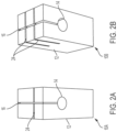
- a single cut 24 perpendicular to the gap 16 results in a second resonance, while a second cut 24 ( Fig. 2B ) parallel to the first cut 24 and perpendicular to the gap 16 results in a third resonance.
- a single perpendicular cut 24 splits the total capacitance in two, resulting in two resonances in the same structure. While the cuts 24 reduce Q, as will be explained in further detail below, the cuts 24 increase the frequency range across which the BLGR is most sensitive to measurements of particular ions for detection.
- the BLGR can be designed to have multiple resonant frequencies by introducing cuts to the structure. While Fig. 2A depicts one cut 24 and Fig. 2B depicts two cuts 24, respectively, it will be recognized that in other various BLGR designs, more cuts may be introduced, including but not limited to, up to six or more cuts.
- the at least one cut 24 may extend into the resonator body 12 from the outer surface 18 of the body 12 across the gap 16 to the aperture 14.
- the gap 16 is aligned with the axis of the aperture 14 through the body 12, and therefore the gap 16 connects to the aperture 14 at the smallest distance from the outer surface 18 to the aperture 14, for a width (w).
- the cuts 24 are exemplarily perpendicular to the gap 16, the cuts 24 may extend into the body 12 at various depths relative to the aperture 14. In an example the cuts 24 extend into the body 12 the same distance (w) as the gap 16. In other examples, the cuts 24 extend through the aperture 14.
- the at least one cut 24 splits the capacitance between the opposing surfaces 22A, 22B into two or more capacitors.
- One cut 24 splits the capacitance into two, while two cuts 24 split the capacitance into three. Additional cuts provide still further capacitances in the BLGR 10.
- Each capacitance results in an additional resonant frequency of the BLGR 10. The lower resonance is dictated by the total capacitance and the higher additional resonant frequenc(ies) are due to the partial capacitance induced by each additional cut 24.
- N is the number of loops, which since the body 12 is a unitary block, a single (1) loop is provided, ⁇ is the permittivity, and aluminum has a conductivity of 3.77 x 10 ⁇ 7 S/m.
- the resonant frequency is independent of the gap length (1). In ion sensing applications, increasing the gap length (1) allows more sample space (and thus improved sensitivity) without modifying the resonant frequency.
- the resonant frequency is inversely proportional to the loop radius (r).
- a dielectric material placed in the gap 16 changes the permittivity as well as the capacitance of the BLGR 10.
- this BLGR 10 As detailed herein, it has been discovered that the electrical properties of this BLGR 10 are dependent upon these physical parameters, therefore, the rest of the resonator body 12 may be designed for other considerations, for example, to provide rigid mounting surfaces, or shape to accommodate other system components or the fluid sample tube 26. This makes the BLGR 10 as described herein convenient for integration of the disclosed sensor system into existing water supply lines for contamination monitoring, as well as a durable construction.
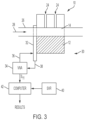
- the VNA 34 supplies an RF energy signal 36 to the coupling loop 32 which transfers such RF energy signal to the BLGR 10 by inductive coupling.
- the BLGR 10 reflects a portion of the RF energy signal 36 back through the coupling loop 32 to the VNA as a reflected RF energy signal 38.
- the VNA compares the provided RF energy signal to the reflected RF energy signal, the ratio of the two being the RF reflection spectrum (S11).
- S11 RF reflection spectrum
- Various ions in solution shift the resonant frequenc(ies) of the BLGR 10. The frequency shift depends upon charge number, concentration, and background of the solution. Solutions with different ions and concentrations of a specific ion (e.g. Pb) result in amplitude and phase variations of the S11 data. Variation can be observed over the entire range of frequency. The variation is more pronounced near the resonances of the BLGR 10.
- VNA vector network analyzer
- the measured portion of the incident signal can be used as a reference for the processor to compute the ratio-based calculations.
- the incident and reflected traveling waves enter the signal -detection block which may use diode detectors and tuned receivers. Conversion of RF signals to proportional DC levels is done with diode detectors.
- local oscillators are used to translate the signal to an intermediate frequency and this signal then passes through bandpass filters.
- the filtered intermediate frequency signal passes through an ADC and DSP to gather magnitude and phase information before the output is transmitted, stored, and/or presented.
- the E8363B vector network analyzer from Agilent Technology with a frequency range of 10MHz - 40 GHz is one example of a VNA that may be used within the present disclosure.
- Z L is the load impedance and Z 0 is the transmission line impedance.
- Z L is not equal to Z 0 , then some of the incident wave will be reflected back and the magnitude of the reflection coefficient will be in the range between 0 and 1.
- the SVR was trained based on error-correcting output codes comprising three binary support vector machine classifiers with 1300 data files from each solution and tested on an additional 200 files of each solution.
- the magnitude and phase vectors corresponding to each sample are normalized to the interval [0,1] and concatenated into a single feature vector. These normalized vectors were used to train and test the SVR algorithm.
- the magnitude and phase vectors correspond to each sample.
- BLGR a BLGR that operates across a frequency of 10 MHz - 10 GHz, or more.
- the BLGR may operate across a frequency range of 10MHz - 7 GHz or 10 MHz - 5 GHz. Still other ranges will be recognized from the present disclosure, in particular in relation to the water exchage rates as discusssed below.
- the BLGR may have an operating frequency range that is larger, the analysis of the S11 measurements may be limited to a frequency band, for example, a 1 GHz frequency band.
- Amplitude changes and frequency shifts are noticeable among different materials and concentrations. Different test materials have different radio frequencies at which they undergo excitation and the responses are identified in S11 measurement. Therefore an algorithm can be trained with appropriate datasets to identify and/or quantify the detected ions across the range of concentrations of 1000 ppm - 400ppb.
- a machine learning algorithm is introduced to analyze the measured S11 data.
- a support vector regressor (SVR) model is trained using the measured data of various salt samples. The training data is constructed by concatenating the 20,000 amplitudes and 20,000 phase values from the measured S11 data. The hyperparameters of the SVR are optimized using 10-fold cross-Validation method.
- a static and non-interfering heavy metal contaminant sensor makes continuous measurements for a heavy metal contaminant (Pb) in water using an AC magnetic field generated by RF resonator.
- Pb heavy metal contaminant
- measurements down to 1 ppb Pb concentration in water may be made.
- the data collected by the RF S11 measurement may be processed by an algorithm trained with machine learning.
- BLGR block loop gap resonator
- Examples of the resonator sensor and measurement technique are described with respect to the detection of various ions in water including, but not limited to, Pb 2+ , Na + , K +, and Mg 2+ .
- the disclosed BLGR is sensitive to different ions and their concentration resulting in S11 amplitude and phase variations in the 10 MHz to 10GHz range. While complex mathematical models may be used to analyze the S11 data, a SVR model as described above may be used. Such analysis may result in the classification of the test ions (Na + , K +, and Mg 2+ ) and to measure Pb 2+ concentrations in water.
- Information of ion concentration and classification may be more pronounced near the resonance(s) of the BLGR.
- a sensing system configured to detect the presence and/or concentration of a plurality of ions, an increased number of resonances in the BLGR has been found to improve detection.
- the BLGR with more cuts 24, e.g. two cuts resulting in three resonances, was found to be the most accurate in quantifying the concentration of Pb ions in the water samples, when the results were analyzed with a general classifier SVR algorithm. Still additional cuts 24 may produce still further resonances which may help to distinguish between ions and lead to improved concentration quantification.
- the BLGR may be tuned, as noted above to be sensitive to detect a particular metal ion in water.
- the BLGR can be tuned by the combination and size of the gap 16 and the one or more cuts 24 in the resonator body to provide a BLGR with a predetermined resonant frequency or frequencies.
- M H 2 O x n + + H 2 O ⁇ ⁇ M H 2 O x ⁇ 1 H 2 O ⁇ n + + H 2 O discovered that a BLGR with a resonant frequency that matches the rate constant for water exchange with a particular metal ion is sensitive to detection of that metal ion.
- the water exchange rate is a unique property of metal ions in water.
- Rate constant values ( k _ w (s -1 )) from three different sources are provided in Table 1, where n/r indicates where a value was not reported in the particular reference.
- Table 1 Rate Constants for Water Exchange with Metal Ions Ion Water Exchange Rate (Morel, Herring 1993) Water Exchange Rate NMR measurements (Margerum 1978) Observation Range (Margerum 1978) Pb 2+ 7 x 10 9 n/r n/r Hg 2+ 2 x 10 9 n/r n/r Cu 2+ 1 x 10 9 1, 5 x 10 9 (.2-5) x 10 9 Ca 2+ 6 x 10 8 n/r (.5-9) x 10 8 Cd 2+ 3 x 10 8 n/r (1-5) x 10 8 La 3+ 1 x 10 8 n/r (.8-2) x 10 8 Zn 2+ 7 x 10 7 n/r (3-50) x 10 7 Mn 2+ 3 x 10 7 2.3 x 10 7 3.1 x
- the water exchange rate can be used in two ways to improve sensitivity of detection and/or quantification of the concentration of a target ion in a water sample.
- the BLGR can be tuned to have a resonant frequency that is the same as, or similar to, the resonant frequency of the target ion.
- differing conditions and quantification techniques result in some differences in the nominal water exchange rate for ions. Therefore further examples of BLGR as disclosed herein may include cuts to produce a BLGR with multiple resonant frequencies to either match the different nominal water exchange rates or to create a resonant frequency band from multiple resonant frequencies that cover the range of nominal water exchange rates.
- the BLGR is configured to produce a resonant frequency at 7GHz, and/or a combination of resonant frequencies to produce a resonant frequency band, for example of 1GHz, centered on the 7GHz frequency.
- the water exchange rates may be used to focus the training and/or implementation of the SVR model to a frequency band that is centered upon or encompasses the frequencies associated with the water exchange rate(s) for the target ion.
- the SVR algorithm uses a 1 GHz band centered on the frequency associated with the water exchange rate, average water exchange rate, weighted average water exchange rate, or water exchange rate observed range to focus the model training and/or focus the application of the SVR model.
- the training is focused on a frequency band including the frequency associated with the water exchange rate of the target ion.
- the training of the SVR model is focused on a 1 GHz frequency band centered on the 7GHz frequency.
- this same 1GHz frequency band of the S11 output signal from the BLGR is analyzed using the SVR model to detect or quantify the target ion in the water sample.
- these techniques that apply the water exchange rate may be used alone or in combination with one another.
- BLGR 10 sensors as disclosed herein may be tuned with a high Q to a narrow frequency range associated with particular ions to produce a highly sensitive sensor to the target ion, or the BLGR 10 sensors may be tuned with a low Q to provide sensing across a wide frequency range with the ability to make robust detection of the presence of a wide range of ions.
Landscapes
- Physics & Mathematics (AREA)
- Health & Medical Sciences (AREA)
- Life Sciences & Earth Sciences (AREA)
- Chemical & Material Sciences (AREA)
- General Physics & Mathematics (AREA)
- Immunology (AREA)
- Biochemistry (AREA)
- General Health & Medical Sciences (AREA)
- Analytical Chemistry (AREA)
- Pathology (AREA)
- Engineering & Computer Science (AREA)
- Food Science & Technology (AREA)
- Medicinal Chemistry (AREA)
- Electromagnetism (AREA)
- Investigating Or Analyzing Materials By The Use Of Electric Means (AREA)
- Investigating Or Analysing Materials By Optical Means (AREA)
Claims (15)
- Resonator (10), umfassend:einen Körper (12), wobei der Körper eine ebene Oberfläche (18) aufweist;eine Öffnung (14) durch den Körper, wobei die Öffnung konfiguriert ist, um einen Schlauch zu empfangen, der für ein zu testendes Fluid konfiguriert ist;einen Spalt (16), der sich von der ebenen Oberfläche bis zur Öffnung in den Körper erstreckt; undmindestens einen Schnitt (24) durch den Körper von der ebenen Oberfläche zur Öffnung, wobei sich der mindestens eine Schnitt über den Spalt erstreckt.
- Resonator nach Anspruch 1, wobei der Körper (12) quaderförmig ist.
- Resonator nach Anspruch 1 oder 2, wobei der Schnitt (24) senkrecht zum Spalt verläuft.
- Resonator nach einem der Ansprüche 1 bis 3, wobei sich der mindestens eine Schnitt (24) von der ebenen Oberfläche (18) zur Öffnung (14) erstreckt.
- Resonator nach einem der Ansprüche 1 bis 4, wobei sich der mindestens eine Schnitt (24) von der ebenen Oberfläche (18) durch die Öffnung (14) erstreckt.
- Resonator nach einem der Ansprüche 1 bis 5, wobei der Körper mindestens zwei Einschnitte (24) umfasst.
- Resonator nach einem der Ansprüche 1 bis 6, wobei der Resonator (10) konfiguriert ist, um eine Resonanzfrequenz zu erzeugen, die einer Wasseraustauschrate eines durch den Resonator zu erfassenden Ions entspricht, und
vorzugsweise das zu detektierende Ion Blei ist und die Resonanzfrequenz 7 Ghz beträgt. - Resonator nach einem der Ansprüche 1 bis 7, wobei der Resonator ferner ein dielektrisches Material in dem Spalt (16) umfasst.
- Resonator nach einem der Ansprüche 1 bis 8, wobei der Resonator eine Resonanzfrequenz für jede Lücke oder jeden Einschnitt im Resonator aufweist.
- System zum Nachweis eines Ions in einem Fluid, das System umfassend:den Resonator (10) nach einem der Ansprüche 1 bis 9;ein Probenrohr (26), das sich durch die Öffnung (14) des Resonators erstreckt, wobei das Probenrohr konfiguriert ist, um eine Probe des Fluids mit dem Ion zu empfangen;eine Kopplungsschleife (32), die eine Drahtspule umfasst, wobei die Drahtspule der Kopplungsschleife koaxial mit der Öffnung (14) des Resonators ausgerichtet ist, wobei sich das Probenrohr durch die Kopplungsschleife erstreckt;einen Vektornetzwerkanalysator (VNA) (34), der mit der Kopplungsschleife verbunden ist, wobei der VNA ein HF-Energiesignal an die Kopplungsschleife liefert, das HF-Energiesignal durch induktive Kopplung an den Resonator übertragen wird und der VNA einen reflektierten Abschnitt des HF-Energiesignals durch die Kopplungsschleife empfängt und einen Reflexionskoeffizienten berechnet; undeinen Prozessor (42), der den Reflexionskoeffizienten empfängt und basierend auf dem Reflexionskoeffizienten bestimmt, ob sich das Ion in dem Fluid befindet.
- System nach Anspruch 10, wobei der Prozessor ein Modell eines Stützvektorregressors (SVR) (40) auf den Reflexionskoeffizienten anwendet, um zu bestimmen, ob sich das Ion in dem Fluid befindet; und
optional der Prozessor ferner eine Konzentration des Ions in dem Fluid bestimmt, indem er das SVR-Modell auf den Reflexionskoeffizienten anwendet. - System nach Anspruch 11, wobei das SVR-Modell von einem maschinellen Lernalgorithmus erzeugt wird, der auf Datensätzen von Reflexionskoeffizientenmessungen von Fluiden mit bekannten Ionenkonzentrationen trainiert wurde.
- System nach Anspruch 12, wobei das SVR-Modell spezifisch für ein Zielion ist und das SR-Modell durch den maschinellen Lernalgorithmus erzeugt wird, der auf Datensätzen von Reflexionskoeffizientenmessungen des Fluids mit bekannten Konzentrationen des Zielionsions erzeugt wurde, und
wobei optional das Analysieren der gemessenen Reflexionskoeffizienten das Analysieren der gemessenen Reflexionskoeffizienten innerhalb eines Durchlassbereichs umfasst, der auf eine Frequenz zentriert ist, die einer Wasseraustauschrate des Zielions entspricht. - Verfahren zum Nachweisen eines Ions in einem Fluid nach einem der Ansprüche 1 bis 13, das Verfahren umfassend:Bereitstellen eines Resonators (10) um ein Rohr (26), das konfiguriert ist, ein zu testendes Fluid zu empfangen;Erzeugen eines Magnetfeldes mit dem Resonator;Messen von Reflexionskoeffizienten als Funktion der Frequenz über einen Frequenzbereich;Analysieren der gemessenen Reflexionskoeffizienten; undBestimmen eines Nachweises des Ions in dem Fluid.
- Verfahren nach Anspruch 14, wobei der Frequenzbereich zwischen 10 MHz und 10 GHz und vorzugsweise zwischen 10 MHz und 5 GHz liegt.
Applications Claiming Priority (3)
| Application Number | Priority Date | Filing Date | Title |
|---|---|---|---|
| US202063067691P | 2020-08-19 | 2020-08-19 | |
| US202063074730P | 2020-09-04 | 2020-09-04 | |
| PCT/US2021/046623 WO2022040385A1 (en) | 2020-08-19 | 2021-08-19 | Continuous heavy metal water contaminant measurement system |
Publications (4)
| Publication Number | Publication Date |
|---|---|
| EP4200600A1 EP4200600A1 (de) | 2023-06-28 |
| EP4200600A4 EP4200600A4 (de) | 2024-09-04 |
| EP4200600C0 EP4200600C0 (de) | 2025-06-25 |
| EP4200600B1 true EP4200600B1 (de) | 2025-06-25 |
Family
ID=80323692
Family Applications (1)
| Application Number | Title | Priority Date | Filing Date |
|---|---|---|---|
| EP21859109.7A Active EP4200600B1 (de) | 2020-08-19 | 2021-08-19 | System zur kontinuierlichen messung von schwermetall-wasserverunreinigungen |
Country Status (5)
| Country | Link |
|---|---|
| US (1) | US20230358718A1 (de) |
| EP (1) | EP4200600B1 (de) |
| CN (1) | CN116391124B (de) |
| CA (1) | CA3189654A1 (de) |
| WO (1) | WO2022040385A1 (de) |
Family Cites Families (17)
| Publication number | Priority date | Publication date | Assignee | Title |
|---|---|---|---|---|
| AT322240B (de) * | 1970-12-18 | 1975-05-12 | Mitsche Roland Dr | Probekörper zur bestimmung der wechselfestigkeit |
| US4480239A (en) * | 1983-02-07 | 1984-10-30 | The Medical College Of Wisconsin Inc. | Loop-gap resonator network |
| DE3412704A1 (de) * | 1983-04-06 | 1984-10-11 | Nippondenso Co., Ltd., Kariya, Aichi | Vorrichtung zum messen des alkoholgehaltes in kraftstoffgemischen |
| JPH03229141A (ja) * | 1990-02-05 | 1991-10-11 | Daipoole:Kk | 糸状材料内の混入導電物質検知装置 |
| FR2661500B1 (fr) * | 1990-04-25 | 1994-01-07 | Aerospatiale Ste Nationale Indle | Cavite hyperfrequence adaptee a la mesure des caracteristiques electromagnetiques d'un materiau filiforme en defilement. |
| JP2004251688A (ja) * | 2003-02-19 | 2004-09-09 | Jeol Ltd | 電子スピン共鳴装置用空胴共振器 |
| US10018613B2 (en) * | 2006-11-16 | 2018-07-10 | General Electric Company | Sensing system and method for analyzing a fluid at an industrial site |
| KR100823931B1 (ko) * | 2007-03-30 | 2008-04-22 | 엘지전자 주식회사 | 원통형 공진기 |
| US8410873B2 (en) * | 2007-09-19 | 2013-04-02 | Ngk Spark Plug Co., Ltd. | Dielectric resonator having a dielectric resonant element with two oppositely located notches for EH mode coupling |
| CN101614681B (zh) * | 2009-06-19 | 2012-11-28 | 周建明 | 谐振腔微扰法微水含量测试系统 |
| GB201209246D0 (en) * | 2012-05-25 | 2012-07-04 | Imp Innovations Ltd | Structures and materials |
| US9410904B2 (en) * | 2013-12-23 | 2016-08-09 | Rosmount Tank Radar Ab | System and method for determining density of a medium in a tank |
| WO2015112688A1 (en) * | 2014-01-22 | 2015-07-30 | Schlumberger Canada Limited | Microwave measurement of water fraction |
| EP3155441A4 (de) * | 2014-06-06 | 2017-12-20 | CTS Corporation | Variables funkfrequenzzustandsmesssystem und -verfahren |
| US10288656B2 (en) * | 2016-11-30 | 2019-05-14 | Nokia Solutions And Networks Oy | Measurement structures for measurements such as frequency and quality factors of resonators and other devices, and apparatus comprising the same |
| KR102319051B1 (ko) * | 2019-01-08 | 2021-11-02 | 주식회사 케이엠더블유 | 도파관 필터 |
| CN210040477U (zh) * | 2019-08-28 | 2020-02-07 | 中兴通讯股份有限公司 | 一种交叉耦合滤波器 |
-
2021
- 2021-08-19 EP EP21859109.7A patent/EP4200600B1/de active Active
- 2021-08-19 WO PCT/US2021/046623 patent/WO2022040385A1/en not_active Ceased
- 2021-08-19 CN CN202180070035.0A patent/CN116391124B/zh active Active
- 2021-08-19 US US18/042,146 patent/US20230358718A1/en active Pending
- 2021-08-19 CA CA3189654A patent/CA3189654A1/en active Pending
Also Published As
| Publication number | Publication date |
|---|---|
| EP4200600C0 (de) | 2025-06-25 |
| EP4200600A4 (de) | 2024-09-04 |
| US20230358718A1 (en) | 2023-11-09 |
| CA3189654A1 (en) | 2022-02-24 |
| CN116391124B (zh) | 2025-12-23 |
| CN116391124A (zh) | 2023-07-04 |
| EP4200600A1 (de) | 2023-06-28 |
| WO2022040385A1 (en) | 2022-02-24 |
Similar Documents
| Publication | Publication Date | Title |
|---|---|---|
| US8618817B2 (en) | Device and method for determining at least one parameter of a medium | |
| US10553926B2 (en) | Coaxial resonant cavity and system and method for measuring dielectric constant of material | |
| Khanna et al. | Dual-Band Microwave Sensor for Investigation of Liquid Impurity Concentration Using a Metamaterial Complementary Split-Ring Resonator: Khanna and Awasthi | |
| US11137359B2 (en) | Nondestructive imaging using a split-ring resonator sensing apparatus | |
| EP2939184B1 (de) | Resonanzsensorbaugruppe zur analyse von flüssigkeiten | |
| US20120001628A1 (en) | Method and apparatus for obtaining spatial information and measuring the dielectric constant of an object | |
| Haddadi et al. | Microwave liquid sensing based on interferometry and microscopy techniques | |
| EP3035039A1 (de) | Messung von zucker in einer lösung | |
| Al-Gburi et al. | Solid characterization utilizing planar microwave resonator sensor | |
| EP4200600B1 (de) | System zur kontinuierlichen messung von schwermetall-wasserverunreinigungen | |
| US20080012578A1 (en) | System for detecting molecular structure and events | |
| EP3308160B1 (de) | Fluidmesssystem | |
| Qi et al. | A quarter-mode substrate integrated waveguide microwave sensor loaded with CCRR for solid material measurement | |
| CN112444681B (zh) | 介电材料测试系统、方法、装置及平台 | |
| Amer et al. | Single-Port Microwave Sensor Using Defected Ground Structure Complementary Split Ring Resonator for Solid Material Characterization | |
| RU2536184C1 (ru) | Концентратомер | |
| RU59239U1 (ru) | Комплекс измерения покомпонентного расхода | |
| Sapuri et al. | Characterization of liquid sample using complementary split ring resonator sensor | |
| Grine et al. | A dual-band HSIW microwave sensor loaded with MCSRR for magnetodielectric material characterization | |
| EP4632315A1 (de) | Einseitiger lithium-ionen-batterie-mikrowellenmessschieber und leitfähigkeitsmessungen | |
| Zheng | Development of Low-Field Pulsed NMR Instrument Probe | |
| Tian et al. | Concentration Measurement of Aqueous Solutions Using Capacitive Coupling between Resonators | |
| CN120352740A (zh) | 一种压电单元与图案化电路联合的超声-特高频一体化传感器 | |
| Yukhanov et al. | Non-Contact Device for Length Measuring and Control of Conductive Objects | |
| RU59813U1 (ru) | Комплекс измерения расхода компонентов потока нефтяных скважин |
Legal Events
| Date | Code | Title | Description |
|---|---|---|---|
| STAA | Information on the status of an ep patent application or granted ep patent |
Free format text: STATUS: THE INTERNATIONAL PUBLICATION HAS BEEN MADE |
|
| PUAI | Public reference made under article 153(3) epc to a published international application that has entered the european phase |
Free format text: ORIGINAL CODE: 0009012 |
|
| STAA | Information on the status of an ep patent application or granted ep patent |
Free format text: STATUS: REQUEST FOR EXAMINATION WAS MADE |
|
| 17P | Request for examination filed |
Effective date: 20230215 |
|
| AK | Designated contracting states |
Kind code of ref document: A1 Designated state(s): AL AT BE BG CH CY CZ DE DK EE ES FI FR GB GR HR HU IE IS IT LI LT LU LV MC MK MT NL NO PL PT RO RS SE SI SK SM TR |
|
| DAV | Request for validation of the european patent (deleted) | ||
| DAX | Request for extension of the european patent (deleted) | ||
| A4 | Supplementary search report drawn up and despatched |
Effective date: 20240805 |
|
| RIC1 | Information provided on ipc code assigned before grant |
Ipc: G01N 33/18 20060101ALI20240730BHEP Ipc: G01N 22/00 20060101AFI20240730BHEP |
|
| GRAP | Despatch of communication of intention to grant a patent |
Free format text: ORIGINAL CODE: EPIDOSNIGR1 |
|
| STAA | Information on the status of an ep patent application or granted ep patent |
Free format text: STATUS: GRANT OF PATENT IS INTENDED |
|
| INTG | Intention to grant announced |
Effective date: 20250115 |
|
| GRAS | Grant fee paid |
Free format text: ORIGINAL CODE: EPIDOSNIGR3 |
|
| GRAA | (expected) grant |
Free format text: ORIGINAL CODE: 0009210 |
|
| STAA | Information on the status of an ep patent application or granted ep patent |
Free format text: STATUS: THE PATENT HAS BEEN GRANTED |
|
| AK | Designated contracting states |
Kind code of ref document: B1 Designated state(s): AL AT BE BG CH CY CZ DE DK EE ES FI FR GB GR HR HU IE IS IT LI LT LU LV MC MK MT NL NO PL PT RO RS SE SI SK SM TR |
|
| REG | Reference to a national code |
Ref country code: GB Ref legal event code: FG4D |
|
| REG | Reference to a national code |
Ref country code: CH Ref legal event code: EP |
|
| REG | Reference to a national code |
Ref country code: CH Ref legal event code: EP |
|
| REG | Reference to a national code |
Ref country code: IE Ref legal event code: FG4D |
|
| REG | Reference to a national code |
Ref country code: DE Ref legal event code: R096 Ref document number: 602021033052 Country of ref document: DE |
|
| U01 | Request for unitary effect filed |
Effective date: 20250723 |
|
| U07 | Unitary effect registered |
Designated state(s): AT BE BG DE DK EE FI FR IT LT LU LV MT NL PT RO SE SI Effective date: 20250730 |
|
| U20 | Renewal fee for the european patent with unitary effect paid |
Year of fee payment: 5 Effective date: 20250806 |
|
| PG25 | Lapsed in a contracting state [announced via postgrant information from national office to epo] |
Ref country code: NO Free format text: LAPSE BECAUSE OF FAILURE TO SUBMIT A TRANSLATION OF THE DESCRIPTION OR TO PAY THE FEE WITHIN THE PRESCRIBED TIME-LIMIT Effective date: 20250925 Ref country code: GR Free format text: LAPSE BECAUSE OF FAILURE TO SUBMIT A TRANSLATION OF THE DESCRIPTION OR TO PAY THE FEE WITHIN THE PRESCRIBED TIME-LIMIT Effective date: 20250926 |
|
| PGFP | Annual fee paid to national office [announced via postgrant information from national office to epo] |
Ref country code: GB Payment date: 20250827 Year of fee payment: 5 |
|
| PG25 | Lapsed in a contracting state [announced via postgrant information from national office to epo] |
Ref country code: HR Free format text: LAPSE BECAUSE OF FAILURE TO SUBMIT A TRANSLATION OF THE DESCRIPTION OR TO PAY THE FEE WITHIN THE PRESCRIBED TIME-LIMIT Effective date: 20250625 |
|
| PG25 | Lapsed in a contracting state [announced via postgrant information from national office to epo] |
Ref country code: RS Free format text: LAPSE BECAUSE OF FAILURE TO SUBMIT A TRANSLATION OF THE DESCRIPTION OR TO PAY THE FEE WITHIN THE PRESCRIBED TIME-LIMIT Effective date: 20250925 |
|
| PG25 | Lapsed in a contracting state [announced via postgrant information from national office to epo] |
Ref country code: IS Free format text: LAPSE BECAUSE OF FAILURE TO SUBMIT A TRANSLATION OF THE DESCRIPTION OR TO PAY THE FEE WITHIN THE PRESCRIBED TIME-LIMIT Effective date: 20251025 |
|
| PG25 | Lapsed in a contracting state [announced via postgrant information from national office to epo] |
Ref country code: SM Free format text: LAPSE BECAUSE OF FAILURE TO SUBMIT A TRANSLATION OF THE DESCRIPTION OR TO PAY THE FEE WITHIN THE PRESCRIBED TIME-LIMIT Effective date: 20250625 |
|
| PG25 | Lapsed in a contracting state [announced via postgrant information from national office to epo] |
Ref country code: CZ Free format text: LAPSE BECAUSE OF FAILURE TO SUBMIT A TRANSLATION OF THE DESCRIPTION OR TO PAY THE FEE WITHIN THE PRESCRIBED TIME-LIMIT Effective date: 20250625 |
|
| PG25 | Lapsed in a contracting state [announced via postgrant information from national office to epo] |
Ref country code: PL Free format text: LAPSE BECAUSE OF FAILURE TO SUBMIT A TRANSLATION OF THE DESCRIPTION OR TO PAY THE FEE WITHIN THE PRESCRIBED TIME-LIMIT Effective date: 20250625 |
|
| PG25 | Lapsed in a contracting state [announced via postgrant information from national office to epo] |
Ref country code: SK Free format text: LAPSE BECAUSE OF FAILURE TO SUBMIT A TRANSLATION OF THE DESCRIPTION OR TO PAY THE FEE WITHIN THE PRESCRIBED TIME-LIMIT Effective date: 20250625 |
|
| PG25 | Lapsed in a contracting state [announced via postgrant information from national office to epo] |
Ref country code: ES Free format text: LAPSE BECAUSE OF FAILURE TO SUBMIT A TRANSLATION OF THE DESCRIPTION OR TO PAY THE FEE WITHIN THE PRESCRIBED TIME-LIMIT Effective date: 20250625 |