EP4200520B1 - Wagen zum zusammenbau und transport eines flugzeugmotors zu einer testzelle - Google Patents
Wagen zum zusammenbau und transport eines flugzeugmotors zu einer testzelle Download PDFInfo
- Publication number
- EP4200520B1 EP4200520B1 EP20767895.4A EP20767895A EP4200520B1 EP 4200520 B1 EP4200520 B1 EP 4200520B1 EP 20767895 A EP20767895 A EP 20767895A EP 4200520 B1 EP4200520 B1 EP 4200520B1
- Authority
- EP
- European Patent Office
- Prior art keywords
- engine
- arms
- cart
- aircraft engine
- adapter
- Prior art date
- Legal status (The legal status is an assumption and is not a legal conclusion. Google has not performed a legal analysis and makes no representation as to the accuracy of the status listed.)
- Active
Links
Images
Classifications
-
- B—PERFORMING OPERATIONS; TRANSPORTING
- B62—LAND VEHICLES FOR TRAVELLING OTHERWISE THAN ON RAILS
- B62B—HAND-PROPELLED VEHICLES, e.g. HAND CARTS OR PERAMBULATORS; SLEDGES
- B62B3/00—Hand carts having more than one axis carrying transport wheels; Steering devices therefor; Equipment therefor
- B62B3/001—Steering devices
-
- B—PERFORMING OPERATIONS; TRANSPORTING
- B62—LAND VEHICLES FOR TRAVELLING OTHERWISE THAN ON RAILS
- B62B—HAND-PROPELLED VEHICLES, e.g. HAND CARTS OR PERAMBULATORS; SLEDGES
- B62B3/00—Hand carts having more than one axis carrying transport wheels; Steering devices therefor; Equipment therefor
- B62B3/02—Hand carts having more than one axis carrying transport wheels; Steering devices therefor; Equipment therefor involving parts being adjustable, collapsible, attachable, detachable or convertible
-
- B—PERFORMING OPERATIONS; TRANSPORTING
- B62—LAND VEHICLES FOR TRAVELLING OTHERWISE THAN ON RAILS
- B62B—HAND-PROPELLED VEHICLES, e.g. HAND CARTS OR PERAMBULATORS; SLEDGES
- B62B3/00—Hand carts having more than one axis carrying transport wheels; Steering devices therefor; Equipment therefor
- B62B3/10—Hand carts having more than one axis carrying transport wheels; Steering devices therefor; Equipment therefor characterised by supports specially adapted to objects of definite shape
-
- B—PERFORMING OPERATIONS; TRANSPORTING
- B62—LAND VEHICLES FOR TRAVELLING OTHERWISE THAN ON RAILS
- B62B—HAND-PROPELLED VEHICLES, e.g. HAND CARTS OR PERAMBULATORS; SLEDGES
- B62B5/00—Accessories or details specially adapted for hand carts
- B62B5/0026—Propulsion aids
-
- B—PERFORMING OPERATIONS; TRANSPORTING
- B64—AIRCRAFT; AVIATION; COSMONAUTICS
- B64F—GROUND OR AIRCRAFT-CARRIER-DECK INSTALLATIONS SPECIALLY ADAPTED FOR USE IN CONNECTION WITH AIRCRAFT; DESIGNING, MANUFACTURING, ASSEMBLING, CLEANING, MAINTAINING OR REPAIRING AIRCRAFT, NOT OTHERWISE PROVIDED FOR; HANDLING, TRANSPORTING, TESTING OR INSPECTING AIRCRAFT COMPONENTS, NOT OTHERWISE PROVIDED FOR
- B64F5/00—Designing, manufacturing, assembling, cleaning, maintaining or repairing aircraft, not otherwise provided for; Handling, transporting, testing or inspecting aircraft components, not otherwise provided for
- B64F5/50—Handling or transporting aircraft components
-
- B—PERFORMING OPERATIONS; TRANSPORTING
- B66—HOISTING; LIFTING; HAULING
- B66C—CRANES; LOAD-ENGAGING ELEMENTS OR DEVICES FOR CRANES, CAPSTANS, WINCHES, OR TACKLES
- B66C1/00—Load-engaging elements or devices attached to lifting or lowering gear of cranes or adapted for connection therewith for transmitting lifting forces to articles or groups of articles
- B66C1/10—Load-engaging elements or devices attached to lifting or lowering gear of cranes or adapted for connection therewith for transmitting lifting forces to articles or groups of articles by mechanical means
- B66C1/62—Load-engaging elements or devices attached to lifting or lowering gear of cranes or adapted for connection therewith for transmitting lifting forces to articles or groups of articles by mechanical means comprising article-engaging members of a shape complementary to that of the articles to be handled
-
- F—MECHANICAL ENGINEERING; LIGHTING; HEATING; WEAPONS; BLASTING
- F01—MACHINES OR ENGINES IN GENERAL; ENGINE PLANTS IN GENERAL; STEAM ENGINES
- F01D—NON-POSITIVE DISPLACEMENT MACHINES OR ENGINES, e.g. STEAM TURBINES
- F01D25/00—Component parts, details, or accessories, not provided for in, or of interest apart from, other groups
- F01D25/28—Supporting or mounting arrangements, e.g. for turbine casing
- F01D25/285—Temporary support structures, e.g. for testing, assembling, installing, repairing; Assembly methods using such structures
-
- F—MECHANICAL ENGINEERING; LIGHTING; HEATING; WEAPONS; BLASTING
- F16—ENGINEERING ELEMENTS AND UNITS; GENERAL MEASURES FOR PRODUCING AND MAINTAINING EFFECTIVE FUNCTIONING OF MACHINES OR INSTALLATIONS; THERMAL INSULATION IN GENERAL
- F16M—FRAMES, CASINGS OR BEDS OF ENGINES, MACHINES OR APPARATUS, NOT SPECIFIC TO ENGINES, MACHINES OR APPARATUS PROVIDED FOR ELSEWHERE; STANDS; SUPPORTS
- F16M1/00—Frames or casings of engines, machines or apparatus; Frames serving as machinery beds
- F16M1/04—Frames or casings of engines, machines or apparatus; Frames serving as machinery beds for rotary engines or similar machines
-
- G—PHYSICS
- G01—MEASURING; TESTING
- G01M—TESTING STATIC OR DYNAMIC BALANCE OF MACHINES OR STRUCTURES; TESTING OF STRUCTURES OR APPARATUS, NOT OTHERWISE PROVIDED FOR
- G01M15/00—Testing of engines
- G01M15/02—Details or accessories of testing apparatus
-
- G—PHYSICS
- G01—MEASURING; TESTING
- G01M—TESTING STATIC OR DYNAMIC BALANCE OF MACHINES OR STRUCTURES; TESTING OF STRUCTURES OR APPARATUS, NOT OTHERWISE PROVIDED FOR
- G01M15/00—Testing of engines
- G01M15/14—Testing gas-turbine engines or jet-propulsion engines
-
- B—PERFORMING OPERATIONS; TRANSPORTING
- B62—LAND VEHICLES FOR TRAVELLING OTHERWISE THAN ON RAILS
- B62B—HAND-PROPELLED VEHICLES, e.g. HAND CARTS OR PERAMBULATORS; SLEDGES
- B62B2202/00—Indexing codes relating to type or characteristics of transported articles
- B62B2202/60—Motors
-
- B—PERFORMING OPERATIONS; TRANSPORTING
- B62—LAND VEHICLES FOR TRAVELLING OTHERWISE THAN ON RAILS
- B62B—HAND-PROPELLED VEHICLES, e.g. HAND CARTS OR PERAMBULATORS; SLEDGES
- B62B2206/00—Adjustable or convertible hand-propelled vehicles or sledges
- B62B2206/003—Adjustable or convertible hand-propelled vehicles or sledges with actuation mechanisms which drive the adjustment or conversion operation
-
- F—MECHANICAL ENGINEERING; LIGHTING; HEATING; WEAPONS; BLASTING
- F05—INDEXING SCHEMES RELATING TO ENGINES OR PUMPS IN VARIOUS SUBCLASSES OF CLASSES F01-F04
- F05D—INDEXING SCHEME FOR ASPECTS RELATING TO NON-POSITIVE-DISPLACEMENT MACHINES OR ENGINES, GAS-TURBINES OR JET-PROPULSION PLANTS
- F05D2230/00—Manufacture
- F05D2230/60—Assembly methods
- F05D2230/68—Assembly methods using auxiliary equipment for lifting or holding
-
- F—MECHANICAL ENGINEERING; LIGHTING; HEATING; WEAPONS; BLASTING
- F05—INDEXING SCHEMES RELATING TO ENGINES OR PUMPS IN VARIOUS SUBCLASSES OF CLASSES F01-F04
- F05D—INDEXING SCHEME FOR ASPECTS RELATING TO NON-POSITIVE-DISPLACEMENT MACHINES OR ENGINES, GAS-TURBINES OR JET-PROPULSION PLANTS
- F05D2260/00—Function
- F05D2260/02—Transport and handling during maintenance and repair
-
- F—MECHANICAL ENGINEERING; LIGHTING; HEATING; WEAPONS; BLASTING
- F05—INDEXING SCHEMES RELATING TO ENGINES OR PUMPS IN VARIOUS SUBCLASSES OF CLASSES F01-F04
- F05D—INDEXING SCHEME FOR ASPECTS RELATING TO NON-POSITIVE-DISPLACEMENT MACHINES OR ENGINES, GAS-TURBINES OR JET-PROPULSION PLANTS
- F05D2260/00—Function
- F05D2260/12—Testing on a test bench
Definitions
- the invention is directed to the field of aircraft engines, in particular of aircraft engine handling like in production assembly line, for repair, inspection and/or testing in a test cell and of transporting an aircraft engine to and from a test cell.
- Test cells are commonly used for testing aircraft engines. Specific test cell equipment is generally used, consisting of a bell-mouth, a cowling or test nacelle, a nozzle and plug, a boat-tail and an adapter.
- the adapter is designed to attach an upper portion of the test nacelle to an upper support in the test cell, so that the aircraft engine and test equipment assembly is properly fastened in the test cell.
- Assembling the aircraft engine and the test equipment requires manipulating the aircraft engine relative to the test equipment, whereas such manipulations are complex, time-consuming and can cause damages to the aircraft engine and the test equipment if done without sufficient care.
- the aircraft engine is usually manipulated by means of a crane or a monorail, i.e. suspended means.
- test equipment sensors, blank-off, starter, harness, fuel pipe
- final assembly of the engine to its adapter and transport of the resulting package assembly to a test cell.
- reverse e.g. once the tests are over, i.e. transporting the assembly out of the test cell and disassembling the aircraft engine from the test equipment.
- Prior art patent document published US 2012/0224944 A1 discloses a cart for handling an aircraft engine during assembly.
- the cart comprises a base frame that can be lifted and towed, and a side frame with rotating carrying means of the core of an aircraft engine.
- This rotating carrying means is configured for receiving the core in a vertical orientation and for pivoting said core to a horizontal orientation for assembly with another module of the aircraft engine.
- That cart is designed for a specific operation in the assembly of an aircraft engine, i.e. is not suitable for assembling a complete aircraft engine with a test equipment.
- Prior art patent document published FR 3 078 058 A1 discloses a cart for transporting an aircraft engine, in particular equipped with thrust reversal, the cart comprising essentially a base frame optionally equipped with wheels, and two side arms pivotally mounted on the base frame with upper ends for engaging with two upper anchoring points of the aircraft engine, located under the outer casing of the nacelle of said engine.
- the cart can also comprise a lower transversal support beam arranged on the base frame, with two lateral ends for engaging with two lower anchoring points of the aircraft engine.
- the purpose and advantage of that cart is to be compact, in particular in width, essentially for facilitating the transport of the aircraft engine. It is not suitable for assembling an aircraft engine to a test equipment and for transporting such an assembly to a test cell.
- Further carts are known from the prior art patent documents US 2017/166331 A1 , FR 2 990 190 A1 , US 6 170 141 B1 and EP 0 868 372 A1 .
- the invention is directed to a cart for transporting an aircraft engine according to claim 1 and to a method of transporting an aircraft engine to a test cell according to claim 11. Further embodiments are defined in the appended dependent claims.
- the adapter is a test equipment adapter, i.e. to secure the aircraft engine to the test cell thrust stand including the test nacelle or cowling.
- the invention is particularly interesting in that it provides an efficient and practical means for assembling an aircraft engine with a test nacelle and also for transporting that assembly to a test cell, and vice versa.
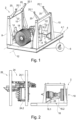
- Figure 1 is a perspective view of a cart for transporting an aircraft engine, according to the invention.
- the cart 2 comprises a base frame 4 that is advantageously generally planar though showing a certain depth, e.g. at least 200mm, equipped with wheels 6 that are for instance hidden in the base frame.
- the wheels 6 are advantageously each steerable and driven in rotation, e.g. by an electric motor.
- the wheels 6 are advantageously structured and designed for allowing the cart to turn on its self, i.e. with a turning radius close or equal to 0.
- the cart 2 comprises also posts 8 and 10 extending vertically from the base frame 4.
- the posts can comprise two front posts 8 and two rear posts 10. Each of them is located adjacent an edge of the base frame 4.
- the two front posts 8 and the two rear posts 10 are located on either sides of a longitudinal axis 12 of the cart 2.
- the cart 2 comprises also engine arms 14 and 16 structured and designed for carrying the aircraft engine 18. These engine arms 14 and 16 extend horizontally and are movable vertically. They are supported by the posts 8 and 10.
- the engine arms comprise for instance two front engine arms 14 carried each by one of the front posts 8.
- the right front engine arm 14 is not visible in figure 1 .
- the engine arms comprise also one rear engine arm 16 carried by one of the rear posts 10, in the present case the right rear post 10.
- Each post 8 and 10 supporting an engine arm 14 or 16 comprises a guiding rail and mechanism for vertically moving the engine arm along the rail. That mechanism can be a thread spindle arranged vertically and engaging with a nut fastened to the corresponding engine arm. Other mechanisms, like a hydraulic cylinder (and not limited to), can be considered.
- the two front engine arms 14 are generally straight and extend perpendicularly to the longitudinal axis 12 of the cart 2 whereas the rear engine arm 16 comprises a first portion 16.1 directly supported by the rear post 10 and extending parallel to the longitudinal axis 12, and a second portion 16.2 pivotally connected to the first portion 16.1, movable between a position where it is essentially in line with the first portion 16.1 and a position where it extends transversally, for instance perpendicularly to the longitudinal axis 12.
- the front and/or rear engine arms 14 and 16 can comprise, each, a distal portion that is removably attached to a main portion of said arm, so as be modular. Each distal removable portion would then be adapted to a particular aircraft engine model or type with a given geometry. The attachment of the distal removable portion to the main portion of the corresponding engine arm can be by self-locking engagement, making use or not of fasteners.
- the engine arms 14 and 16 can be engaged with the corresponding front and rear posts 8 and 10 in a removable manner so as to be easily replaced by others adapted to another type of engine.
- the cart 2 comprises also adapter arms 20 located at higher position than the engine arms 14 and 16 and configured for engaging with an adapter of a test equipment, as this will be detailed below in connection with figures 6 .
- the adapter arms 20 comprise in the present embodiment four adapter arms 20, i.e. two adapter arms 20 on each side of the longitudinal axis 12 of the cart 2.
- the adapter arms 20 are designed for working in unison, i.e. do not need to be movable relative to each other.
- each pair of adapter arms 20, on each side of the longitudinal axis 12 of the cart 2 is rigidly fastened to a common longitudinal beam 22 supported by the corresponding front post 8 and rear post 10.
- the longitudinal beam 22 is advantageously pivotally mounted on the front post 8 and rear post 10, about a longitudinal axis. This pivoting movement is for moving the adapter arms 20 from an active position where they extend essentially horizontally to an inactive position where they free or widen, compared with the active position, a central area of access from above, as illustrated in figure 1 , and vice versa.
- the adapter arms remain fixed in the active position, e.g. by means of appropriate arresting and/or abutting means (not visible or not represented) in the pivoting connection between the longitudinal beams 22 and the corresponding front and rear posts 8 and 10.
- the wheels 6 are mounted on the base frame 4 such that said base frame can be selectively lifted or lowered relative to said wheels 6, so as to selectively lift or lower the adapter arms 20.
- the base frame can comprise integrated jacks configured for being lowered so as to contact the ground and raise said base frame 4 upwardly, similarly to outriggers and stabilizers on mobile cranes.
- the adapter arms 20 can be movable vertically, similarly to the engine arms 14 and 16, in which case the base frame 4 does not need to be vertically movable relative to the wheels 6 or the ground.
- the adapter arms 20 comprise each a free end 20.1 with a recessed upper profile structured and designed for securely engaging with the adapter.
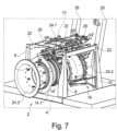
- the engine arms whereas this is not visible in figure 1 but well in figure 7 (see 14.1).
- the base frame 4 advantageously comprises a generally planar floor 4.1 particularly adequate for enabling and facilitating personnel to work on and around the aircraft engine 18 while supported by the engine arms 14 and 16 as illustrated in figure 1 .
- the cart 2 can comprise a control unit of the wheels 6 structured and designed for enabling the cart to move as a self-driven vehicle. It can also comprise guiding means along a track on the floor, e.g. optical and/or magnetic detecting means, laser scanning (but not limited to), for enabling the cart to move in an autonomous way along the track, similarly to carts carrying parts or workpieces in a production factory, from one workstation to a next one in a safe way (personnel and equipment protection).
- guiding means along a track on the floor e.g. optical and/or magnetic detecting means, laser scanning (but not limited to)
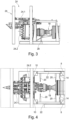
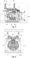
- Figure 1 to 7 illustrate also successive phases of a method of transporting an aircraft engine to a test cell, according to the invention.
- the aircraft engine 18 is placed on the engine arms 14 and 16 by an external means like a crane.
- the adapter arms 20 are advantageously brought in their inactive position freeing or widening, compared with the active position, a central area of access from above, as illustrated in figure 1 .
- the aircraft engine 18 is carried at its front portion by the two front engine arms 14 and at its rear portion by the (right) rear engine arm 16. In that position, at arms' height, the engine can be comfortably further assembled and/or prepared for the test.
- test equipment 24 placed on a support 26.
- the test equipment 24 comprises for instance an adapter 24.1 and a test nacelle 24.2 attached at its upper portion to the adapter 24.1.
- a test equipment 24 is as such known from the skilled person and does not need to be specifically further detailed.
- the rear portion of the aircraft engine 18 is oriented towards the main opening of the test nacelle 24.2 in order to penetrate it.
- a central post 28 is placed below the rear portion of the aircraft engine 18 so as to carry said rear portion.
- the rear engine arm 16 is disengaged from the engine rear portion and pivoted to the inactive position where it extends completely longitudinally, i.e. where the second portion 16.2 is aligned with the first portion 16.1.
- the cart 2 with the aircraft engine 18 is further moved towards the test equipment 24, where the rear portion of the aircraft engine 18 starts to penetrate the test nacelle 24.2.
- the rear engine arm 16 does not interfere with the test nacelle 24.2 for it is brought to the inactive position extending between the corresponding front post 8 and rear post 10.
- the adapter arms 20 are brought in their active position in order to pass below the adapter 24.1 when the cast 2 is further moved towards the test equipment 24.
- test nacelle is essentially made of two half-shells hinged together at an upper portion adjacent to the adapter 24.1 and separated from each other at a lower portion (see figure 6 ), enabling the central post 28 to pass freely through that free lower space.
- the aircraft engine 18 has reached its final position relative to the test nacelle 24.2.
- the rear engine arm 16 can be brought back to its active position, i.e. by bringing the second portion thereof (not visible in figure 5 ) in a transversal position extending towards the rear portion of the aircraft engine 18 so as to engage again with said engine.
- the rear engine arm 16, once engaged back with the aircraft engine 18 can be slightly lifted so as to release the central post 28 which can then be removed.
- the aircraft engine 18 is then carried by the two front engine arms 14 and the rear engine arm 16. Its position relative to the test nacelle 24.2 can be finely adjusted by adjusting the height of the engine arms 14 and 16. Once the position of the aircraft engine 18 is mated with the test nacelle 24.2, said engine is rigidly fastened to the test nacelle 24.2.
- the engine arms 14 and 16 can then be lowered so as to be disengaged from the aircraft engine 18 while the latter and the test nacelle 24.2 are held in position by the adapter 24.1 placed on the support 26.
- the test equipment 24 can comprise a bell-mouth 24.3 simulating the inlet of the real nacelle of the aircraft. That bell-mouth 24.3 can be mounted on the front portion of the aircraft engine 18 once the aircraft engine 18 has reached its final position relative to the test nacelle 24.2.
- the adapter arms 20 are lifted to as to engage with the adapter 24.1 and lift said adapter from the support 26.
- that movement can be achieved by lifting the base frame 4 relative to the wheels (not visible) while the adapter arms 20 remain in a fixed position relative to the base frame 4. Still with reference with the above discussion, this can also be achieved by a relative movement of the adapter arms 20.
- the cart 2 can move away from the support 26 either by a reverse movement or a forward movement.
- the aircraft engine and test nacelle assembly 18+24.2 is then supported exclusively by the adapter arms 20 via the adapter 24.1.
- Figure 7 shows the cart 2 carrying the aircraft engine and test nacelle assembly 18+24.2 after disengagement of the support 26 as mentioned in relation with figure 6 .
- the cart 2 can then transport the aircraft engine and test nacelle assembly 18+24.2 to a test cell.
Landscapes
- Engineering & Computer Science (AREA)
- Transportation (AREA)
- Mechanical Engineering (AREA)
- Chemical & Material Sciences (AREA)
- Combustion & Propulsion (AREA)
- Physics & Mathematics (AREA)
- General Physics & Mathematics (AREA)
- General Engineering & Computer Science (AREA)
- Manufacturing & Machinery (AREA)
- Aviation & Aerospace Engineering (AREA)
- Testing Of Engines (AREA)
Claims (15)
- Wagen (2) zum Transportieren eines Flugzeugtriebwerks (18), der Folgendes umfasst:einen Grundrahmen (4), der mit Rädern (6) zum Fahren auf einem Boden ausgestattet ist;mindestens zwei Triebwerksarme (14, 16), die sich horizontal erstrecken und in Bezug auf den Grundrahmen (4) vertikal beweglich sind, und die so strukturiert und ausgelegt sind, dass sie das Flugzeugtriebwerk (18) tragen; unddadurch gekennzeichnet, dass er außerdem mindestens zwei Adapterarme (20) umfasst, die sich horizontal auf einem höheren Niveau als die mindestens zwei Triebwerksarme (14, 16) erstrecken und die so strukturiert und ausgelegt sind, dass sie einen Adapter (24.1) tragen, der mit einer Testgondel (24.2) an der Oberseite des Flugzeugtriebwerks (18) gekoppelt ist.
- Wagen (2) nach Anspruch 1, wobei die mindestens zwei Triebwerksarme (14, 16) auf zwei gegenüberliegenden Seiten des Grundrahmens (4) angeordnet sind.
- Wagen (2) nach einem der Ansprüche 1 und 2, wobei die mindestens zwei Adapterarme (20) an zwei gegenüberliegenden Seiten des Grundrahmens (4) angeordnet sind, vorzugsweise wobei die mindestens zwei Adapterarme (20) an den zwei gegenüberliegenden Seiten des Grundrahmens (4) angeordnet sind, an denen die mindestens zwei Triebwerksarme (14, 16) angeordnet sind.
- Wagen (2) nach einem der Ansprüche 1 bis 3, wobei jeder der mindestens zwei Triebwerksarme (14, 16) und der mindestens zwei Adapterarme (20) ein freies Ende (20.1) mit einem vertieften oberen Profil aufweist, das für einen sicheren Eingriff mit dem Flugzeugtriebwerk (18) bzw. dem Adapter (24.1) strukturiert und ausgelegt ist.
- Wagen (2) nach einem der Ansprüche 1 bis 4, wobei sich jeder der mindestens zwei Triebwerksarme (14, 16) und Adapterarme (20) in Richtung einer zentralen Längsachse des Wagens erstreckt.
- Wagen (2) nach einem der Ansprüche 1 bis 5, ferner umfassend:
mindestens zwei Pfosten (8, 10), die sich starr vom Grundrahmen (4) aus erstrecken und die mindestens zwei Triebwerksarme (14, 16) und die mindestens zwei Adapterarme (20) tragen, wobei die mindestens zwei Pfosten (8, 10) vorzugsweise mindestens vier der genannten Pfosten umfassen, und wobei die mindestens zwei Pfosten (8, 10) vorzugsweise eine Führungs- und Antriebseinheit für jeden der mindestens zwei Triebwerksarme (14, 16) umfassen. - Wagen (2) nach einem der Ansprüche 1 bis 6, wobei die mindestens zwei Triebwerksarme (14, 16) Folgendes umfassen:zwei vordere Triebwerksarme (14), die sich gegenüberliegen und quer zu einer zentralen Längsachse des Wagens erstrecken; undmindestens einen hinteren Triebwerksarm (16), der so strukturiert und gestaltet ist, dass er horizontal zwischen einer aktiven Position, die sich quer zur zentralen Längsachse des Wagens erstreckt, und einer inaktiven Position, die sich parallel zu dieser zentralen Längsachse erstreckt, schwenken kann.
- Wagen (2) nach einem der Ansprüche 1 bis 7, wobei die mindestens zwei Adapterarme (20) zwischen einer aktiven Position, die sich in Richtung einer zentralen Längsachse des Wagens erstreckt, und einer inaktiven Position, die im Vergleich zur aktiven Position einen zentralen Zugangsbereich von oben freigibt oder verbreitert, beweglich sind.
- Wagen (2) nach einem der Ansprüche 1 bis 8, wobei die Räder (6) so auf dem Grundrahmen (4) montiert sind, dass der Grundrahmen selektiv relativ zu den Rädern (6) angehoben oder abgesenkt werden kann.
- Wagen (2) nach einem der Ansprüche 1 bis 9, wobei jedes der Räder (6) lenkbar ist und/oder wobei mindestens zwei der Räder (6) angetrieben sind.
- Verfahren zum Transportieren eines Flugzeugtriebwerks (18) zu einer Testzelle, dadurch gekennzeichnet, dass es die folgenden Schritte umfasst:Zusammenbau des Flugzeugtriebwerks (18) mit einer Testgondel (24.2), die an einem Adapter (24.1) befestigt ist, der auf einem Träger (26) ruht; undTransportieren des Flugzeugtriebwerks (18) und der Testgondelanordnung (24) zur Testzelle;wobei die Schritte des Zusammenbaus und des Transports unter Verwendung eines Wagens (2) durchgeführt werden, der Folgendes umfasst:einen Grundrahmen (4), der mit Rädern (6) zum Fahren auf einem Boden ausgestattet ist;mindestens zwei Triebwerksarme (14, 16); undmindestens zwei Adapterarme (20);wobei der Zusammenbauschritt die folgenden Teilschritte umfasst: Positionieren und Befestigen des Flugzeugtriebwerks (18) in Bezug auf die Testgondel (24.2), während das Flugzeugtriebwerk (18) von den mindestens zwei Triebwerksarmen (14, 16) getragen wird;Anheben der mindestens zwei Adapterarme (20), so dass sie in den Adapter (24.1) eingreifen und die Baugruppe aus Flugzeugtriebwerk (18) und Testgondel (24) tragen.
- Verfahren nach Anspruch 11, wobei der Teilschritt des Positionierens und Befestigens die folgenden Aktionen umfasst:Tragen eines vorderen Teils des Flugzeugtriebwerks (18) mit zwei vorderen Triebwerksarmen (14) der mindestens zwei Triebwerksarme (14, 16) und Tragen eines hinteren Teils des besagten Flugzeugtriebwerks (18) mit einem zentralen Pfosten (28), der sich auf dem Grundrahmen (4) abstützt, während der besagte hintere Teil in die Testgondel (24.2) eingesetzt ist, die einen geöffneten unteren Teil aufweist;Ausfahren von mindestens einem hinteren Triebwerksarm (16) der mindestens zwei Triebwerksarme (14, 16), um den hinteren Teil des Flugzeugtriebwerks (18) zu tragen;Verbinden des Flugzeugtriebwerks (18) mit der Testgondel (24.2) durch Bewegen der Triebwerksarme (14, 16) relativ zum Grundrahmen (4); undBefestigen des Flugzeugtriebwerks (18) an der Testgondel (24.2):
wobei der Teilschritt des Positionierens und Befestigens vorzugsweise zwischen dem Entfalten und dem Zusammenfügen Folgendes umfasst:
das Entfernen des zentralen Pfostens (28). - Verfahren nach einem der Ansprüche 11 und 12, wobei der Teilschritt Anheben das Anheben des Grundrahmens (4) relativ zum Boden umfasst.
- Verfahren nach einem der Ansprüche 11 bis 13, wobei der Zusammenbauschritt zwischen dem Positionierungs- und Befestigungs-Teilschritt und dem Hebe-Teilschritt den folgenden zusätzlichen Teilschritt umfasst:
das Freigeben der mindestens zwei Triebwerksarme (14, 16). - Verfahren nach einem der Ansprüche 11 bis 14, wobei der Wagen (2) während der Montage- und Transportschritte selbstangetrieben und gelenkt wird.
Applications Claiming Priority (1)
| Application Number | Priority Date | Filing Date | Title |
|---|---|---|---|
| PCT/US2020/046907 WO2022039731A1 (en) | 2020-08-19 | 2020-08-19 | Cart for assembling and transporting an aircraft engine to a test cell |
Publications (2)
| Publication Number | Publication Date |
|---|---|
| EP4200520A1 EP4200520A1 (de) | 2023-06-28 |
| EP4200520B1 true EP4200520B1 (de) | 2024-10-09 |
Family
ID=72381129
Family Applications (1)
| Application Number | Title | Priority Date | Filing Date |
|---|---|---|---|
| EP20767895.4A Active EP4200520B1 (de) | 2020-08-19 | 2020-08-19 | Wagen zum zusammenbau und transport eines flugzeugmotors zu einer testzelle |
Country Status (5)
| Country | Link |
|---|---|
| US (1) | US12459669B2 (de) |
| EP (1) | EP4200520B1 (de) |
| CN (1) | CN116096637B (de) |
| CA (1) | CA3187849A1 (de) |
| WO (1) | WO2022039731A1 (de) |
Families Citing this family (2)
| Publication number | Priority date | Publication date | Assignee | Title |
|---|---|---|---|---|
| CN116952441B (zh) * | 2023-07-21 | 2025-04-25 | 上海交通大学 | 一种航空发动机推力实测评估装置及方法 |
| US20260021896A1 (en) * | 2024-07-22 | 2026-01-22 | Pratt & Whitney Canada Corp. | Aircraft engine assembly stand and method of using the same |
Citations (1)
| Publication number | Priority date | Publication date | Assignee | Title |
|---|---|---|---|---|
| EP0868372B1 (de) * | 1995-11-30 | 2002-03-06 | Stanley Aviation Corporation | Jettriebwerkstransportvorrichtung |
Family Cites Families (9)
| Publication number | Priority date | Publication date | Assignee | Title |
|---|---|---|---|---|
| US5575607A (en) * | 1994-11-02 | 1996-11-19 | United Technologies Corporation | Jet engine transport vehicle lift system and a build cell |
| US6170141B1 (en) * | 1998-09-25 | 2001-01-09 | Stanley Aviation Corporation | Shipping system for jet aircraft engine and method of installing and removing jet aircraft engine |
| FR2952922B1 (fr) | 2009-11-20 | 2012-05-25 | Snecma | Ensemble de manutention d'un module de moteur d'aeronef |
| FR2990190B1 (fr) * | 2012-05-02 | 2015-06-19 | Snecma | Outil de manutention d'un module de moteur d'aeronef |
| FR3017112B1 (fr) * | 2014-02-03 | 2017-09-29 | Snecma | Structure de transport et de hissage pour turbomachine |
| DE102015214669B4 (de) * | 2015-07-31 | 2020-11-19 | MTU Aero Engines AG | Führungswagen für ein Triebwerkbauteil |
| FR3075760B1 (fr) * | 2017-12-21 | 2020-01-31 | Safran Nacelles | Nacelle de moteur d’aeronef |
| FR3078058B1 (fr) | 2018-02-20 | 2022-03-25 | Safran Nacelles | Ensemble de motorisation pour aeronef comportant des points de levage, et chariots pour supporter un tel ensemble |
| US10723485B2 (en) * | 2018-04-18 | 2020-07-28 | The Boeing Company | Apparatus that supports an aircraft fuselage without exterior surface contact |
-
2020
- 2020-08-19 US US18/022,226 patent/US12459669B2/en active Active
- 2020-08-19 WO PCT/US2020/046907 patent/WO2022039731A1/en not_active Ceased
- 2020-08-19 CN CN202080103183.3A patent/CN116096637B/zh active Active
- 2020-08-19 CA CA3187849A patent/CA3187849A1/en active Pending
- 2020-08-19 EP EP20767895.4A patent/EP4200520B1/de active Active
Patent Citations (1)
| Publication number | Priority date | Publication date | Assignee | Title |
|---|---|---|---|---|
| EP0868372B1 (de) * | 1995-11-30 | 2002-03-06 | Stanley Aviation Corporation | Jettriebwerkstransportvorrichtung |
Also Published As
| Publication number | Publication date |
|---|---|
| WO2022039731A1 (en) | 2022-02-24 |
| CA3187849A1 (en) | 2022-02-24 |
| CN116096637B (zh) | 2026-03-06 |
| US20230322411A1 (en) | 2023-10-12 |
| US12459669B2 (en) | 2025-11-04 |
| EP4200520A1 (de) | 2023-06-28 |
| CN116096637A (zh) | 2023-05-09 |
Similar Documents
| Publication | Publication Date | Title |
|---|---|---|
| US5645389A (en) | Shipping frame from fan section of aircraft engine | |
| US5575607A (en) | Jet engine transport vehicle lift system and a build cell | |
| EP4200520B1 (de) | Wagen zum zusammenbau und transport eines flugzeugmotors zu einer testzelle | |
| US8573921B2 (en) | Method and a device for lifting and rotating a massive container | |
| JP4891871B2 (ja) | 変圧器輸送組立方法およびu字形鉄心組立装置 | |
| CN117226498B (zh) | 一种用于航空发动机大部件对接的装配系统 | |
| US20130145770A1 (en) | Substitution device for aircraft engine | |
| CN210049214U (zh) | 一种检修小车 | |
| JPS6033188A (ja) | 船底部の改造工法 | |
| US12280892B2 (en) | Cradle for an aircraft landing gear assembly | |
| CN218518547U (zh) | 燃料电池发动机旋转式装配工装 | |
| CN109250649A (zh) | 便携式车辆举升机及使用该举升机进行车辆举升的方法 | |
| CN117183999A (zh) | 换电站及换电方法 | |
| CN113322837A (zh) | 一种跨座式单轨的检修车 | |
| KR101022460B1 (ko) | 항공기 엔진 장착장치 | |
| CN220180751U (zh) | 一种漏斗车底门开闭减速器检修装置 | |
| CN118809114B (zh) | 伸缩支腿的自动化装配系统、装配设备及装配方法 | |
| CN223328883U (zh) | 一种大型水轮发电机组调速器检修专用工装 | |
| CN120117344B (zh) | 大型精密设备厂房内水平自动化运输装置及使用方法 | |
| CN121735130A (zh) | 一种极限工况辅助吊装装置及方法 | |
| CN215728807U (zh) | 一种四维精准调节的声呐换能器试验用定位装置 | |
| CN116765776A (zh) | 一种横向竖向混合的设备入舱装置及方法 | |
| JPH0511161B2 (de) | ||
| KR102063588B1 (ko) | 피니언 기어 수직 고정 이동차 및 이를 이용한 피니언 기어 수직 고정 방법 | |
| CN118776892A (zh) | 一种叶栅式反推力装置在试车台的安装方法 |
Legal Events
| Date | Code | Title | Description |
|---|---|---|---|
| STAA | Information on the status of an ep patent application or granted ep patent |
Free format text: STATUS: UNKNOWN |
|
| STAA | Information on the status of an ep patent application or granted ep patent |
Free format text: STATUS: THE INTERNATIONAL PUBLICATION HAS BEEN MADE |
|
| PUAI | Public reference made under article 153(3) epc to a published international application that has entered the european phase |
Free format text: ORIGINAL CODE: 0009012 |
|
| STAA | Information on the status of an ep patent application or granted ep patent |
Free format text: STATUS: REQUEST FOR EXAMINATION WAS MADE |
|
| 17P | Request for examination filed |
Effective date: 20230320 |
|
| AK | Designated contracting states |
Kind code of ref document: A1 Designated state(s): AL AT BE BG CH CY CZ DE DK EE ES FI FR GB GR HR HU IE IS IT LI LT LU LV MC MK MT NL NO PL PT RO RS SE SI SK SM TR |
|
| DAV | Request for validation of the european patent (deleted) | ||
| DAX | Request for extension of the european patent (deleted) | ||
| RIC1 | Information provided on ipc code assigned before grant |
Ipc: G01M 15/14 20060101ALI20240624BHEP Ipc: G01M 15/02 20060101ALI20240624BHEP Ipc: F16M 1/04 20060101ALI20240624BHEP Ipc: B66C 1/62 20060101ALI20240624BHEP Ipc: B64F 5/50 20170101ALI20240624BHEP Ipc: F01D 25/28 20060101AFI20240624BHEP |
|
| GRAP | Despatch of communication of intention to grant a patent |
Free format text: ORIGINAL CODE: EPIDOSNIGR1 |
|
| STAA | Information on the status of an ep patent application or granted ep patent |
Free format text: STATUS: GRANT OF PATENT IS INTENDED |
|
| GRAS | Grant fee paid |
Free format text: ORIGINAL CODE: EPIDOSNIGR3 |
|
| INTG | Intention to grant announced |
Effective date: 20240806 |
|
| GRAA | (expected) grant |
Free format text: ORIGINAL CODE: 0009210 |
|
| STAA | Information on the status of an ep patent application or granted ep patent |
Free format text: STATUS: THE PATENT HAS BEEN GRANTED |
|
| AK | Designated contracting states |
Kind code of ref document: B1 Designated state(s): AL AT BE BG CH CY CZ DE DK EE ES FI FR GB GR HR HU IE IS IT LI LT LU LV MC MK MT NL NO PL PT RO RS SE SI SK SM TR |
|
| REG | Reference to a national code |
Ref country code: CH Ref legal event code: EP |
|
| REG | Reference to a national code |
Ref country code: DE Ref legal event code: R096 Ref document number: 602020039153 Country of ref document: DE |
|
| REG | Reference to a national code |
Ref country code: IE Ref legal event code: FG4D |
|
| REG | Reference to a national code |
Ref country code: LT Ref legal event code: MG9D |
|
| REG | Reference to a national code |
Ref country code: NL Ref legal event code: MP Effective date: 20241009 |
|
| REG | Reference to a national code |
Ref country code: AT Ref legal event code: MK05 Ref document number: 1730802 Country of ref document: AT Kind code of ref document: T Effective date: 20241009 |
|
| PG25 | Lapsed in a contracting state [announced via postgrant information from national office to epo] |
Ref country code: NL Free format text: LAPSE BECAUSE OF FAILURE TO SUBMIT A TRANSLATION OF THE DESCRIPTION OR TO PAY THE FEE WITHIN THE PRESCRIBED TIME-LIMIT Effective date: 20241009 |
|
| PG25 | Lapsed in a contracting state [announced via postgrant information from national office to epo] |
Ref country code: NL Free format text: LAPSE BECAUSE OF FAILURE TO SUBMIT A TRANSLATION OF THE DESCRIPTION OR TO PAY THE FEE WITHIN THE PRESCRIBED TIME-LIMIT Effective date: 20241009 |
|
| PG25 | Lapsed in a contracting state [announced via postgrant information from national office to epo] |
Ref country code: IS Free format text: LAPSE BECAUSE OF FAILURE TO SUBMIT A TRANSLATION OF THE DESCRIPTION OR TO PAY THE FEE WITHIN THE PRESCRIBED TIME-LIMIT Effective date: 20250209 Ref country code: PT Free format text: LAPSE BECAUSE OF FAILURE TO SUBMIT A TRANSLATION OF THE DESCRIPTION OR TO PAY THE FEE WITHIN THE PRESCRIBED TIME-LIMIT Effective date: 20250210 Ref country code: HR Free format text: LAPSE BECAUSE OF FAILURE TO SUBMIT A TRANSLATION OF THE DESCRIPTION OR TO PAY THE FEE WITHIN THE PRESCRIBED TIME-LIMIT Effective date: 20241009 |
|
| PG25 | Lapsed in a contracting state [announced via postgrant information from national office to epo] |
Ref country code: FI Free format text: LAPSE BECAUSE OF FAILURE TO SUBMIT A TRANSLATION OF THE DESCRIPTION OR TO PAY THE FEE WITHIN THE PRESCRIBED TIME-LIMIT Effective date: 20241009 |
|
| PG25 | Lapsed in a contracting state [announced via postgrant information from national office to epo] |
Ref country code: BG Free format text: LAPSE BECAUSE OF FAILURE TO SUBMIT A TRANSLATION OF THE DESCRIPTION OR TO PAY THE FEE WITHIN THE PRESCRIBED TIME-LIMIT Effective date: 20241009 |
|
| PG25 | Lapsed in a contracting state [announced via postgrant information from national office to epo] |
Ref country code: ES Free format text: LAPSE BECAUSE OF FAILURE TO SUBMIT A TRANSLATION OF THE DESCRIPTION OR TO PAY THE FEE WITHIN THE PRESCRIBED TIME-LIMIT Effective date: 20241009 |
|
| PG25 | Lapsed in a contracting state [announced via postgrant information from national office to epo] |
Ref country code: NO Free format text: LAPSE BECAUSE OF FAILURE TO SUBMIT A TRANSLATION OF THE DESCRIPTION OR TO PAY THE FEE WITHIN THE PRESCRIBED TIME-LIMIT Effective date: 20250109 |
|
| PG25 | Lapsed in a contracting state [announced via postgrant information from national office to epo] |
Ref country code: LV Free format text: LAPSE BECAUSE OF FAILURE TO SUBMIT A TRANSLATION OF THE DESCRIPTION OR TO PAY THE FEE WITHIN THE PRESCRIBED TIME-LIMIT Effective date: 20241009 Ref country code: GR Free format text: LAPSE BECAUSE OF FAILURE TO SUBMIT A TRANSLATION OF THE DESCRIPTION OR TO PAY THE FEE WITHIN THE PRESCRIBED TIME-LIMIT Effective date: 20250110 Ref country code: AT Free format text: LAPSE BECAUSE OF FAILURE TO SUBMIT A TRANSLATION OF THE DESCRIPTION OR TO PAY THE FEE WITHIN THE PRESCRIBED TIME-LIMIT Effective date: 20241009 |
|
| PG25 | Lapsed in a contracting state [announced via postgrant information from national office to epo] |
Ref country code: PL Free format text: LAPSE BECAUSE OF FAILURE TO SUBMIT A TRANSLATION OF THE DESCRIPTION OR TO PAY THE FEE WITHIN THE PRESCRIBED TIME-LIMIT Effective date: 20241009 |
|
| PG25 | Lapsed in a contracting state [announced via postgrant information from national office to epo] |
Ref country code: RS Free format text: LAPSE BECAUSE OF FAILURE TO SUBMIT A TRANSLATION OF THE DESCRIPTION OR TO PAY THE FEE WITHIN THE PRESCRIBED TIME-LIMIT Effective date: 20250109 |
|
| PG25 | Lapsed in a contracting state [announced via postgrant information from national office to epo] |
Ref country code: SM Free format text: LAPSE BECAUSE OF FAILURE TO SUBMIT A TRANSLATION OF THE DESCRIPTION OR TO PAY THE FEE WITHIN THE PRESCRIBED TIME-LIMIT Effective date: 20241009 |
|
| PG25 | Lapsed in a contracting state [announced via postgrant information from national office to epo] |
Ref country code: DK Free format text: LAPSE BECAUSE OF FAILURE TO SUBMIT A TRANSLATION OF THE DESCRIPTION OR TO PAY THE FEE WITHIN THE PRESCRIBED TIME-LIMIT Effective date: 20241009 |
|
| REG | Reference to a national code |
Ref country code: DE Ref legal event code: R097 Ref document number: 602020039153 Country of ref document: DE |
|
| PG25 | Lapsed in a contracting state [announced via postgrant information from national office to epo] |
Ref country code: EE Free format text: LAPSE BECAUSE OF FAILURE TO SUBMIT A TRANSLATION OF THE DESCRIPTION OR TO PAY THE FEE WITHIN THE PRESCRIBED TIME-LIMIT Effective date: 20241009 |
|
| PG25 | Lapsed in a contracting state [announced via postgrant information from national office to epo] |
Ref country code: RO Free format text: LAPSE BECAUSE OF FAILURE TO SUBMIT A TRANSLATION OF THE DESCRIPTION OR TO PAY THE FEE WITHIN THE PRESCRIBED TIME-LIMIT Effective date: 20241009 |
|
| PG25 | Lapsed in a contracting state [announced via postgrant information from national office to epo] |
Ref country code: SK Free format text: LAPSE BECAUSE OF FAILURE TO SUBMIT A TRANSLATION OF THE DESCRIPTION OR TO PAY THE FEE WITHIN THE PRESCRIBED TIME-LIMIT Effective date: 20241009 |
|
| PG25 | Lapsed in a contracting state [announced via postgrant information from national office to epo] |
Ref country code: CZ Free format text: LAPSE BECAUSE OF FAILURE TO SUBMIT A TRANSLATION OF THE DESCRIPTION OR TO PAY THE FEE WITHIN THE PRESCRIBED TIME-LIMIT Effective date: 20241009 |
|
| PG25 | Lapsed in a contracting state [announced via postgrant information from national office to epo] |
Ref country code: IT Free format text: LAPSE BECAUSE OF FAILURE TO SUBMIT A TRANSLATION OF THE DESCRIPTION OR TO PAY THE FEE WITHIN THE PRESCRIBED TIME-LIMIT Effective date: 20241009 |
|
| PLBE | No opposition filed within time limit |
Free format text: ORIGINAL CODE: 0009261 |
|
| STAA | Information on the status of an ep patent application or granted ep patent |
Free format text: STATUS: NO OPPOSITION FILED WITHIN TIME LIMIT |
|
| PG25 | Lapsed in a contracting state [announced via postgrant information from national office to epo] |
Ref country code: SE Free format text: LAPSE BECAUSE OF FAILURE TO SUBMIT A TRANSLATION OF THE DESCRIPTION OR TO PAY THE FEE WITHIN THE PRESCRIBED TIME-LIMIT Effective date: 20241009 |
|
| 26N | No opposition filed |
Effective date: 20250710 |
|
| PGFP | Annual fee paid to national office [announced via postgrant information from national office to epo] |
Ref country code: DE Payment date: 20250819 Year of fee payment: 6 |
|
| PGFP | Annual fee paid to national office [announced via postgrant information from national office to epo] |
Ref country code: BE Payment date: 20250825 Year of fee payment: 6 Ref country code: GB Payment date: 20250825 Year of fee payment: 6 |
|
| PGFP | Annual fee paid to national office [announced via postgrant information from national office to epo] |
Ref country code: FR Payment date: 20250821 Year of fee payment: 6 |
|
| REG | Reference to a national code |
Ref country code: CH Ref legal event code: H13 Free format text: ST27 STATUS EVENT CODE: U-0-0-H10-H13 (AS PROVIDED BY THE NATIONAL OFFICE) Effective date: 20260324 |
|
| PG25 | Lapsed in a contracting state [announced via postgrant information from national office to epo] |
Ref country code: MC Free format text: LAPSE BECAUSE OF FAILURE TO SUBMIT A TRANSLATION OF THE DESCRIPTION OR TO PAY THE FEE WITHIN THE PRESCRIBED TIME-LIMIT Effective date: 20241009 |
|
| PG25 | Lapsed in a contracting state [announced via postgrant information from national office to epo] |
Ref country code: LU Free format text: LAPSE BECAUSE OF NON-PAYMENT OF DUE FEES Effective date: 20250819 |
|
| PG25 | Lapsed in a contracting state [announced via postgrant information from national office to epo] |
Ref country code: CH Free format text: LAPSE BECAUSE OF NON-PAYMENT OF DUE FEES Effective date: 20250831 |