EP4200224B1 - Récipient de distribution inversé - Google Patents
Récipient de distribution inversé Download PDFInfo
- Publication number
- EP4200224B1 EP4200224B1 EP22711418.8A EP22711418A EP4200224B1 EP 4200224 B1 EP4200224 B1 EP 4200224B1 EP 22711418 A EP22711418 A EP 22711418A EP 4200224 B1 EP4200224 B1 EP 4200224B1
- Authority
- EP
- European Patent Office
- Prior art keywords
- container
- shoulder
- nozzle
- container body
- product
- Prior art date
- Legal status (The legal status is an assumption and is not a legal conclusion. Google has not performed a legal analysis and makes no representation as to the accuracy of the status listed.)
- Active
Links
Images


Classifications
-
- B—PERFORMING OPERATIONS; TRANSPORTING
- B65—CONVEYING; PACKING; STORING; HANDLING THIN OR FILAMENTARY MATERIAL
- B65D—CONTAINERS FOR STORAGE OR TRANSPORT OF ARTICLES OR MATERIALS, e.g. BAGS, BARRELS, BOTTLES, BOXES, CANS, CARTONS, CRATES, DRUMS, JARS, TANKS, HOPPERS, FORWARDING CONTAINERS; ACCESSORIES, CLOSURES, OR FITTINGS THEREFOR; PACKAGING ELEMENTS; PACKAGES
- B65D25/00—Details of other kinds or types of rigid or semi-rigid containers
- B65D25/38—Devices for discharging contents
- B65D25/40—Nozzles or spouts
- B65D25/48—Separable nozzles or spouts
-
- B—PERFORMING OPERATIONS; TRANSPORTING
- B65—CONVEYING; PACKING; STORING; HANDLING THIN OR FILAMENTARY MATERIAL
- B65D—CONTAINERS FOR STORAGE OR TRANSPORT OF ARTICLES OR MATERIALS, e.g. BAGS, BARRELS, BOTTLES, BOXES, CANS, CARTONS, CRATES, DRUMS, JARS, TANKS, HOPPERS, FORWARDING CONTAINERS; ACCESSORIES, CLOSURES, OR FITTINGS THEREFOR; PACKAGING ELEMENTS; PACKAGES
- B65D35/00—Pliable tubular containers adapted to be permanently or temporarily deformed to expel contents, e.g. collapsible tubes for toothpaste or other plastic or semi-liquid material; Holders therefor
- B65D35/02—Body construction
- B65D35/10—Body construction made by uniting or interconnecting two or more components
-
- B—PERFORMING OPERATIONS; TRANSPORTING
- B65—CONVEYING; PACKING; STORING; HANDLING THIN OR FILAMENTARY MATERIAL
- B65D—CONTAINERS FOR STORAGE OR TRANSPORT OF ARTICLES OR MATERIALS, e.g. BAGS, BARRELS, BOTTLES, BOXES, CANS, CARTONS, CRATES, DRUMS, JARS, TANKS, HOPPERS, FORWARDING CONTAINERS; ACCESSORIES, CLOSURES, OR FITTINGS THEREFOR; PACKAGING ELEMENTS; PACKAGES
- B65D47/00—Closures with filling and discharging, or with discharging, devices
- B65D47/04—Closures with discharging devices other than pumps
- B65D47/06—Closures with discharging devices other than pumps with pouring spouts or tubes; with discharge nozzles or passages
- B65D47/12—Closures with discharging devices other than pumps with pouring spouts or tubes; with discharge nozzles or passages having removable closures
- B65D47/122—Threaded caps
- B65D47/123—Threaded caps with internal parts
Definitions
- Containers and other types of packaging are known for the retention and exhibition of fluids or gels such as cleaning products, fabric care products, oral care products, etc.
- Such containers are typically formed with a primary packaging container having a cap attached thereto, the cap having a dispensing opening. To dispense the product from the container, the container is typically squeezed to force a quantity of the product out of the opening.
- dispensing results in a deformation of the container, thus making it more difficult to apply further pressure to dispense additional quantities of the product.
- WO 2015/002110 A1 an ophthalmic preparation container including a container body having a liquid-accommodating part and a cylindrical neck part connected to the liquid-accommodating part; a cover member having a nozzle part for liquid pouring and an engaging part capable of engaging with the container body, the cover member being engaged with the container body so as to cover the cylindrical neck part; and a cap for opening and closing a pouring mouth of the nozzle part.
- a cylindrical plug portion projects from the lower surface of the cover wall portion of the cap. The plug portion is connected to the nozzle portion of the cover member and inserted into the spout of the nozzle portion.
- a container for dispensing a composition is set forth in claim 1.
- the present invention may be directed, in one aspect, to a container designed to hold and/or transfer one or more substances.
- the container comprises a container body extending along a longitudinal axis from a bottom end to a top end, the container body defining an internal cavity for holding the composition.
- the container body further comprises a neck having a container opening open to the internal cavity, a front wall, a rear wall and a pair of side walls extending between the front and rear wall and a shoulder comprising a pair of first shoulder walls extending between the neck and a respective side wall of the container body, the first shoulder walls extending at a first non-perpendicular angle with respect to the longitudinal axis.
- the container further comprises a shoulder fitting attached to the neck, the shoulder fitting extending over the first and second shoulders of the container body and including a nozzle extending therethrough, the nozzle open to the opening.
- the container includes a cap removably received over the container body, the cap being transparent.
- the cap is fitted with a shroud received therein, the shroud having a size and shape complementary to a size and shape of the shoulder fitting.
- the shroud may be formed of an opaque material so as to be visible through the cap.
- the shroud of the cap may threadedly engage the shoulder fitting. An end wall of the shroud may abut against the nozzle opening in a closed configuration when the cap is positioned over the container body.
- the present invention is directed to a container for dispensing a composition
- the container comprising a container body extending along a longitudinal axis from a bottom end to a top end, the container body defining an internal cavity for holding the composition.
- the container body further comprises a neck having a container opening open to the internal cavity, a front wall, a rear wall and a pair of side walls extending between the front and rear wall, and a shoulder comprising a pair of first shoulder walls extending between the neck and a respective side wall of the container body, the first shoulder walls extending at a first non-perpendicular angle with respect to the longitudinal axis.
- the container further comprises a shoulder fitting attached to the neck, the shoulder fitting extending over the first and second shoulders of the container body and including a nozzle extending therethrough, the nozzle open to the opening.
- the container further comprises a cap removably received over the container body and a shroud attached to an inner surface of the cap, the shroud having a size and shape complementary to a size and shape of the shoulder fitting.
- the present invention is directed to a container for dispensing a composition
- the container comprising a container body extending along a longitudinal axis from a bottom end to a top end, the container body defining an internal cavity for holding the composition.
- the container body comprises a neck having a container opening open to the internal cavity, a front wall, a rear wall and a pair of side walls extending between the front and rear wall and a shoulder comprising a pair of first shoulder walls extending between the neck and a respective side wall of the container body and a pair of second shoulder walls extending between the neck and a respective one of the front wall and real wall, the first shoulder walls extending at a first non-perpendicular angle with respect to the longitudinal axis, the second shoulder wall forming a second non-perpendicular angle with respect to the longitudinal axis, the second angle being different from the first angle.
- the container further comprises a shoulder fitting attached to the neck, the shoulder fitting including a nozzle extending therethrough, the nozzle open to the opening, wherein each of the first shoulder walls extends at an angle of 65 degrees with respect to the longitudinal axis wherein the shoulder further comprises a pair of second shoulder walls extending between the neck and a respective one of the front wall and real wall, wherein the second shoulder wall forms a second non-perpendicular angle with respect to the longitudinal axis, the second angle being different from the first angle.
- the proposed container described herein is configured for inverted storage, wherein a cap of the container rests on a table, counter or other flat or substantially flat surface.
- the container is configured with a geometry selected to aid in a flow of a composition out of the container at a predetermined flow rate.
- the container and components thereof, including but not limited to, the nozzle dimensions and container shoulder and opening are configured to control the flow rate of the composition out of the container to a predetermined flow rate. This flow rate is selected to permit dispensing of a quantity of the composition while preventing excess flow which can lead to waste or cause a buildup of the composition in the cap.
- the exemplary container minimizes the amount of physical effort required to dispense said quantity of composition.
- a dispensing force applied to the container may instead force the air bubble out of the container, which may cause the composition to sputter or spray out of the container.
- the exemplary container described herein is configured so as to guide air in through a dispensing nozzle during and/or after dispensing, wherein the construction of the container guides said air along a path that is not congruent with a flow path of the composition itself, as will be described in greater detail later on.
- This exemplary configuration also utilizes a nozzle configured to permit flow thereoutof only when a compressive force is applied to the container, thus preventing unwanted leakage thereoutof.
- a nozzle diameter and a length of a channel extending through the nozzle have been selected to ensure that flow remains within a predetermined desirable range.
- the exemplary nozzle forgoes the need for a membrane or unidirectional valve therein, thus reducing manufacturing cost and time.
- the exemplary container described herein is formed with components that are fully recyclable and acceptable into the current recycling stream.
- the exemplary container described herein is configured so as to allow for evacuation of a greater quantity of the product stored therein as compared to standard containers. That is, the exemplary shoulder and nozzle configuration of the container described herein permits the evacuation of a greater quantity of the product so that, when a consumer or other user has finished using the product, there is little to no product remaining in the container.
- the exemplary container described herein is not only formed of recyclable materials, but is also formed with a design which aids in evacuation of all or nearly all of the contents thereoutof so that the container can be accepted into the recycling stream.
- the exemplary container 100 described herein comprises a shoulder fitting 154 received over an entirety of an end portion of the container body, including an opening and shoulders thereof.
- the exemplary shoulder fitting is configured to mate with a respectively formed shroud in a cap to stably seat the container body on the cap in the inverted configuration.
- the exemplary container 100 is able to incorporate more intricate features that allow for greater control of the flow path therethrough than with a standard blow-molded bottle. That is, the shoulder fitting is configured for attachment onto the container body after filling of said container body with a desired product, thus allowing for faster filling of the container during a manufacturing step.
- the exemplary shoulder fitting 154 may be formed with a nozzle provided over only an opening in the container body, the exemplary shoulder fitting comprises a shoulder fitting that extends over both the opening of the container body as well as the shoulders thereof.
- Container 100 may include a container body 102 having a top end 104, a bottom end 106 having an opening 103 formed therein, and a middle portion 108. The middle portion 108 may be located between the top end 104 and the bottom end 106.
- Container body 102 may extend along a longitudinal axis L from bottom end 104 to top end 106.
- An outer surface of the container body 102 may include a curved dip or depression at the middle portion108.
- the container body 102 may include a linear tapered outer geometry.
- Container body 102 may define an internal cavity, such as internal cavity 110 housing a store of a product, such as one or more fluidic substances, gels, solids ⁇ e.g., powder and/or tablets), gases, combinations of one or more of the substances, or the like.
- a product 112 stored in the internal cavity 110 may be an oral care composition having a paste or gel consistency.
- the product 112 may be a liquid or solid.
- a cap 200 may be removably coupled to the container body 102, as will be discussed in greater detail later on.
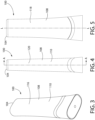
- the container body 102 is discussed in greater detail with respect to Figures 6-9 .
- the container body 102 comprises an elongated body extending from the top end 104 to the bottom end 106, and having a front surface 116, rear surface 118 and a pair of lateral side surfaces 120 extending between each of the front and rear surfaces 116, 118.
- the bottom end 106 further comprises a shoulder portion 122 and a reduced diameter neck 124.
- An outer surface of the shoulder portion 120 is defined by a first curvilinear cutout 126 formed on the front surface 116, an upper edge 128 of the cutout 126 following a U-shaped curvature with an apex or peak 130 aligned with the central longitudinal axis L on each of the front and rear surfaces 116, 118.
- the upper edge 128 forms valleys 132 along each of the side surfaces 120, wherein each of the two valleys 132 of the upper edge 128 are closer to the top end 104 than the respective peaks 130, only one of which is shown
- Container 100 may be formed of one or more of polyolefins (polypropylenes, low, medium and high density polyethylenes).
- Container 100 may be formed of one or more of polyethylene terephthalate (“PET') (e.g., made via injection stretch blow molding) and/or elastomeric materials.
- PET' polyethylene terephthalate
- Container 100 may be formed via one or more combinations of the above. In other examples, container 100 may be formed of one or more other materials.
- the shoulder portion 122 further comprises a pair of shoulders 134, 136 which, due to the cutout 126, have a reduced outer profile as compared to the adjacent portion of the container body 102 above the cutout 126.
- Each of the shoulders 134, 136 comprises a first wall 138 extending in alignment with the longitudinal axis L of the container body 102 and a second wall 140 connected to the first wall 138 along a shoulder edge 142.
- the shoulder edge 142 may be formed as a beveled surface having a predetermined surface area.
- the first wall 138 may extend at an angle to the longitudinal axis L of the container body 102. For example, as shown in greater detail in Fig.
- the first wall 138 may enclose an angle ⁇ of between 0 and 45° relative to the longitudinal axis L.
- the angle ⁇ is selected to ensure a secure fit (e.g. a friction fit) with a shoulder fitting 154 received over the shoulder portion 122.
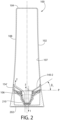
- the second wall 140 is formed with a predetermined and precisely calculated angle to control the flow of both the product 112 and air therepast. Specifically, a first portion 140-1 of the second wall 140 located on each of the front surface 116 and rear surface 118 is angled so as to enclose an angle ⁇ 1 with a plane P extending perpendicular to the longitudinal axis L.
- the angle ⁇ 1 may range from 20-60°, and more specifically from 40-50°, and more specifically 47-50°. Described another way, the first portion 140-1 may be angled at an angle of 65° or approximately 65° with respect to the longitudinal axis L.
- a portion 140-2 of the second wall extending along the side surfaces 120 encloses an angle ⁇ 2 with the plane P intersecting the longitudinal axis L, the plane P extending parallel to a surface upon which the container 100 rests ( i.e., the plane extending parallel to a plane housing a planar surface 202 of the cap 200. That is, the exemplary container 100 has found that an angle ⁇ 2 of 25° provides a flow passageway promoting flow of the product 112 out of the container 100.
- the exemplary angle ⁇ 2 of the invention has been selected to allow for air flow into the container 100 along a desired flow path. That is, with reference to Fig. 2 , as product 112 exits the container in direction 1 ( i.e., upon application of a compressive force to an outside of the container body 102), air is permitted to enter the container body 102 in direction 2.
- the angle ⁇ 2 guides air into the container body 102 along a path indicated by directional arrow 2 toward side walls of the container.
- presently available devices guide air into a container in a direction 3 directly into a product housed in the container.
- the product is not a liquid, such as in the present case, any air flowing into the container in the direction 3 becomes trapped in the container body as air bubbles.
- air bubbles hinder further dispensing of the product, requiring an excessive force (i.e., a force greater than a force required for an initial dispensing) to dispense further quantities of the product).
- the trapped air bubble gets pushed back out of the nozzle, thus resulting in a spurting of the product.
- the exemplary angled shoulder of the container 100 is configured so that any air flowing into the container 100 is guided away from the central longitudinal axis L of the container so that subsequent dispensing results in the same flow rate as the initial dispensing and prevents a sputtering of the product out of the nozzle, thus minimizing/avoiding a wastage of the product, preventing the product from splattering onto unwanted surfaces, and avoiding the need to apply excessive force when dispensing subsequent quantities of the product.
- the exemplary angle ⁇ 2 permits a flow of the product 112 out of the container 100 at a controlled rate, the flow terminating upon release of a compressive force on the outer surface of the container body 102.
- angle ⁇ 2 is 25° when measured with respect to the plane P.
- the angle ⁇ 2 may alternatively range from 20-90° with respect to the plane P, and more specifically 25-55° with respect to the plane P and, more specifically 25-40 with respect to the plane P.
- the wall 140-2 may be angled at an angle of 0-70° relative to the longitudinal axis L, and more specifically 35-65° with respect to the longitudinal axis L and, more specifically 50-65° with respect to the longitudinal axis L and, more specifically 65° with respect to the longitudinal axis L.
- a diameter of the opening 103 may be increased when the angle is reduced and the diameter may be decreased when the angle is increased, so as to provide a controlled rate of flow thereoutof.
- the diameter of the opening 103 may remain the same.
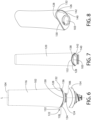
- the neck 124 of the container body 102 is formed with an upwardly tapered beveled lip 144 extending from an elongated shaft 146, wherein an outer diameter of the tapered beveled lip 144 is greater than an outer diameter of the elongated shaft 146.
- a planar wall 148 is provided on the tapered beveled lip 144 opposite the bottom end 106, the combination of the tapered beveled lip 144 and planar wall 148 permitting shoulder fitting 154 to be lockingly fitted over the shoulder portion 122.
- the tapered beveled lip 144 further comprises one or more cutout tab 150 extending at least partially thereinto, the cutout tab 150 allowing for a partial deformation of the lip 144 as the shoulder fitting 154 is slid thereonto.
- any plurality of tabs are envisioned (e . g ., two tabs 150 separated from one another by 180 degrees across the outer circumference of the lip 144, three tabs 150, each tab 150 separated from an adjacent tab by 120 degrees, four tabs 150, each tab 150 separated from an adjacent tab by 90 degrees, etc.).
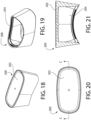
- the shoulder fitting 154 is configured and adapted to be received over the shoulder portion 122 of the container body 102.
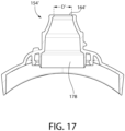
- the shoulder fitting 154 extends from a first end 156 comprising a nozzle 158 to a second end 160 comprising a base 162.
- the nozzle 158 comprises an opening 164, which when the shoulder fitting 154 is in position on the container body 102, is open to the product 112 stored therein.
- a diameter of the opening 164 is selected to permit a predetermined flow rate out of the container 100. That is, extensive testing has been undertaken to determine a nozzle opening diameter which permits flow thereoutof at a desired flow rate while minimizing and/or preventing the buildup of negative pressure within the container 100 as the product 112 is being dispensed, as will be described in greater detail later on.
- the nozzle 158 comprises a first portion 157 having a substantially conical shape terminating in a slightly enlarged lip 161 and a second portion 159 having a cylindrical shape and having one or more screw threads 163 formed on an outer surface thereof, the screw threads 163 being sized, configured and arranged to engage respectively formed groove(s) 222 formed in the cap 200, as will be discussed in greater detail later on.
- the shoulder fitting 154 further comprises one or more thread starters 166 configured to aid in alignment of screw threads 163 with respective groove(s) 222 formed in the cap 200.
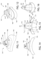
- the base 162 comprises a domed region 168 centered about the longitudinal axis L.
- An outer surface of the domed region 168 is configured to rest within a respective groove 230 formed in shroud 210 of cap 200, as will be discussed in greater detail later on.
- An inner surface 169 of the domed region 168 comprises a first circular rib 170 extending in alignment with the longitudinal axis L, a first surface 171 of the first circular rib 170 including a protuberance 172.
- a circular groove 173 is defined between the first surface 171 of the first circular rib 170 and a second surface 175 of a second circular rib 174, the circular groove 173 receiving the neck 124 of the container body 102 therein.
- the shoulder fitting 154 is positioned in place over the bottom end 106 of the container body 102 and pressed thereonto such that the tapered lip 144 is received within the circular groove 173.
- engagement of the tapered wall of lip 144 with the protuberance 172 may cause one or both of a radially outward deflection of the first circular rib 170 and a radially inward deflection of the lip 144.
- engagement of the planar wall 148 with the protuberance 172 lock the shoulder fitting 154 in place over the container body 102.
- the base 162 further comprises a band 176, the band 176 having an outer profile substantially matching a cross-sectional shape of the container body 102 such that, when the shoulder fitting 154is lockingly fitted over the container body 102, the band 176 is seated flush with the outer surface of the container body 102.
- An inner surface 177 of the band 176 is configure d and dimensioned to come into contact with the first and second walls 138, 140 of the shoulders 134, 136.
- the opening 164 is open to a channel 178 extending through the shoulder fitting 154.
- the channel 178 may include an orifice restrictor 179 limiting a flow of the product 112 therepast.
- the orifice restrictor may be formed of any of a silicone, polyethylene or other known material.
- the orifice restrictor 179 may be formed of the same material as the shoulder fitting 154 or a different material.
- the orifice restrictor 179 is separated from the opening 164 at the end of the shoulder fitting nozzle 158 by a predetermined distance of 1-5 mm, preferably 2-3 mm. In one example, the orifice restrictor 179 may be separated from the opening 164 by 2.3 mm.
- the exemplary orifice restrictor 179 is merely a narrowed portion of the channel 178 and permits two-way flow therepast to allow for flow of the product 112 out of the container 100 while also allowing for airflow thereinto to maintain a pressure equilibrium in the container.
- the construction of the container 100 is specifically formulated so that a one-way valve is not necessary at the nozzle, the container 100 allowing for a predetermined rate of flow thereoutof without the problem of excess flow and/or leakage.
- the orifice restrictor 179 is separated from the nozzle opening by a minimum non-zero distance L 2 , as depicted in Figure 15 .
- the distance L 2 may be selected to provide a relief to allow for ease of removal of the shoulder fitting 154 from a mold during a formation process.
- the separation distance L 2 allows for some flexing of the nozzle during both manufacturing and use.
- a shoulder fitting 154' may be formed substantially similar to shoulder fitting 154, with the exception that no orifice restrictor 179 is included in the channel 178.
- a diameter D' of opening 164' may be smaller than diameter D of opening 164. That is, whereas diameter D may be in the range of 5-10 mm, preferably 7 -8 mm, and more preferably 7.2 mm, the diameter D' may be in the range of 5-10 mm, preferably 6 -7 mm, and more preferably 6.6 mm.
- a diameter DV of opening 180 of the orifice restrictor 179 may be approximately 2-3 mm, preferable 2.8 mm.
- a spout length SL of the channel 178 of the shoulder fitting 154 is selected to ensure a predetermined flow rate out of the container 100 as well as minimizing entrapment of the product within the nozzle. That is, through extensive testing, it has been determined that a longer spout length SL results in an undesirable effect of the product (i.e., an oral care composition) sticking to the inner surface of the nozzle. For example, a spout length SL of 12.7 mm was determined to be preferable over a spout length SL of 15.3 mm, as will be described hereinafter.
- spout lengths ranging from 12.7mm - 21.4 mm have been tested; a spout length of 12.7 mm - 18.8 mm is preferable for optimizing flow of the product thereoutof and flow of air thereinto while also providing a good line of sight to a user when dispensing the product 112.
- the exemplary nozzle 158 is configured and dimensioned with a preselected inner surface area.
- the inner surface area of the nozzle 158 is defined as the portion of the inner surface of the nozzle 158 coinciding with channel 178, as depicted for example in Figs. 15-16 .
- the inner surface area is the portion of the inner surface of the nozzle 158 that comes into contact with the product 112 as the product 112 is being dispensed.
- the exemplary nozzle 158 is dimensioned with a length SL and nozzle diameter D selected to yield a desired inner surface area. In a preferred embodiment where the nozzle diameter D is 7.2 mm and the length SL is 12.7 mm, the inner surface area is 468-470 mm 2 .
- the diameter DV may be 2.8 mm and the inner surface area may be 456 mm 2 .
- the exemplary nozzle 158 is configured to minimize the spout length SL and increase the nozzle diameter D so as to reduce the volume of product 112 that comes into physical contact with the inner surface of the nozzle, so as to prevent the product 112 from adhering to the inner surface of the nozzle. This configuration foregoes the need to apply a coating (e . g ., LiquiGlide, etc.) to the inner surface of the nozzle and instead, facilitates flow of the product 112 past the nozzle.
- a coating e . g ., LiquiGlide, etc.
- present containers are formed with an enlarged inner surface area which often causes a product to become trapped within the nozzle, thus impeding the dispensing of said product.
- the nozzle was formed with a smaller diameter D of 6 mm and a longer length SL of 15.3mm, resulting in an inner surface area of 1426 mm 2 .
- this nozzle resulted in a product being trapped within the nozzle or otherwise becoming adhered to the inner surface of the nozzle, thus hindering dispensing of the product or inadvertently causing an excess of the product to be dispensed due to the added compressive pressure required to dispense the product past the nozzle.
- testing has found that a correlative variation in the diameter D of the opening 164 affects the flow rate.
- testing was performed wherein a diameter D of 6.0mm was found to yield too low of a flow rate while an increase in diameter D to, for example, 7.2mm, yields a more desirable flow rate.
- the preferred flow rate in the exemplary configuration allows for a controlled dispensing of the product 112 from the nozzle 158 while also permitting air to enter the nozzle 158 ( i.e., via the opening 164) to prevent a buildup of negative air pressure within the container 100 during and after dispensing.
- the exemplary nozzle 158 is formed so as to provide a desired line of sight LS aiding in visualization of the product within the nozzle 158 so as to aid in dispensing thereof.
- the line of sight LS defines an angle at which a user orients the container 100 when dispensing the product 112 onto, for example, an oral care implement.
- the exemplary nozzle diameter D, spout length SL, conically shaped nozzle and width of the band 176 together provide a line of sight LS of 29°, said angle LS enabling a user to view at least a portion of the product 112 as the product exits the opening164.
- the line of sight is an angle formed between the longitudinal axis L of the container body and shoulder fitting and a tangential plane TP extending tangentially to the shoulder fitting 154 and intersecting said shoulder fitting at the This exemplary angle aids in dispensing of the product 112 and provides a greater degree of user control of the dispensing as opposed to a container configured with a line of sight which does not enable visualization of the product as it is being dispensed from the container.
- the angle LS may be any angle under 30°.
- the angle LS may be 29° or 17°. It is noted that these values are exemplary only and other values of less than 30° are envisioned within the scope of the invention.
- R D SA
- R 0.0100
- D is 5 mm and SA is 385mm 2 , yielding an R value of 0.0129. This configuration yields a preferred flow which aids in guiding air into the nozzle as the product is dispensed thereoutof, while also directing air along the side of the nozzle.
- This exemplary configuration allows for the dispensing of a viscous product 112 such as a gel or paste-like composition (i.e., a non-liquid product) without encountering the problem of air pockets becoming entrapped within the product.
- a viscous product 112 such as a gel or paste-like composition (i.e., a non-liquid product)
- the gel /paste-like product 112 has a higher viscosity than a liquid such as water which does not encounter the problem of air pockets becoming trapped therewithin as it is being dispensed.
- the exemplary nozzle and container described herein allows for the dispensing of a higher viscosity product without encountering the problem or air pockets becoming entrapped within the product, which impedes proper dispensing of the product.
- a nozzle 158 was tested with an inner surface area of 830mm 2 and an orifice diameter D of 6.5mm.
- Figs. 18-21 depict the cap 200 without a shroud 210 received therein.
- the cap 200 comprises a planar surface 202 upon which the container 100 rests in an operative configuration.
- the cap 200 is hollow, having an opening 204 formed therein, the opening 204 sized and shaped to lockingly receive the shroud 210 therein.
- the cap 200 may be formed of polyethylene and, one embodiment, may be formed of polyethylene terephthalate (PET) having a glossy surface finish.
- PET polyethylene terephthalate
- the cap 200 is transparent, although an opaque material is also envisioned.
- the shroud 210 is opaque.
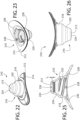
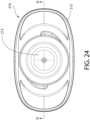
- the shroud 210 is described in greater detail with respect to Figs. 22-26 .
- An outer periphery 212 of a first end 214 of the shroud 210 is configured to be seated flush within the cap 200 so that no portion of the shroud 210 extends out of the cap 200, as seen for example in Fig. 2 .
- a nozzle receiving portion 216 of the shroud is configured to seat the first and second portions 157, 159 of the nozzle 158 therein, a shape of the nozzle receiving portion 216 substantially matching the substantially matching the shape of the nozzle 158 ( i.e., having a cylindrical component 218 and a substantially conical portion 220).
- An inner surface of the nozzle receiving portion 216 included one or more threaded grooves 222 configured to threadedly engage screw threads 163.
- a second end 213 of the shroud 210 is closed via a wall 224.
- An inner surface of the wall 224 comprises a job 226, a diameter of which is one of equal to, substantially equal to or smaller than a diameter of the opening 164.
- the job 226 is housed within the opening 164, thus sealing or plugging the channel 178, prevented any unwanted flow thereoutof when the container 100 is in the closed, inverted configuration.
- the inner surface of the shroud 216 further comprises at least one groove 228 sized and shaped to receive thread starters 166 therein and a curved groove 230 sized and shaped to receive domed region 168 therein.
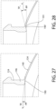
- the container body 102 is formed with an exemplary internal geometry designed to provide a transitional wall 190 between the elongated shaft 146 of neck 124 and the second wall 140 of the shoulder 134.
- the transitional wall 190 is formed so as to minimize protrusion thereof into the internal cavity 110 of the container body 102. That is, the transitional wall 190 is configured such that a first tangential plane TP 1 extending tangentially to the transitional wall 190 is substantially aligned with a perpendicular plane PP extending perpendicular to the longitudinal axis and parallel to a surface upon which the container 100 may rest.
- Fig. 28 depicts a non-preferred transitional wall 190' having a bump 191 formed thereon, the transitional wall 190' configured such that a second tangential plane TP 2 extending tangentially to the transitional wall 190' is not substantially aligned with the perpendicular plane PP.
- an angle ⁇ 1 enclosed between planes TP 1 and PP is a negative angle while an angle ⁇ 2 enclosed between planes TP 2 and PP is a positive angle.
- the transitional wall 190' leads to formation of the bump 191 within the container 102, which inhibits flow of the product 112 out of the container 100 while also altering the path of flow of air into the container.
- the exemplary container body 102 is formed with a predetermined quantity of materials so that no bumps are formed at the transitional wall 190 during a blow molding process.
- the exemplary container body 102 is formed and an inner surface thereof is coated with a predetermined quantity of a coating 107.
- a coefficient of friction between the product 112 and the coating 107 may be less than a coefficient of friction between the product 112 and an inner surface of the body 102.
- the coating 107 may prevent the product 112 from sticking to the inner surface of the body 102, thereby allowing the product 112 to slide or slosh or otherwise move around within the internal volume of the body 102 when the user rotates the container 100.
- the coating 107 may be or include a liquid-impregnated surface, as described in U.S. Pat. No. 8,940,361 .
- the coating 107 may include a matrix of solid features spaced sufficiently close to stably contain a liquid therebetween or therewithin.
- the coating 107 may be or include LiquiGlide ®TM manufactured by LiquiGlide Inc. of Cambridge, Massachusetts.
- the container body 102 may be filled with the product 112.
- the shoulder fitting 154 is then positioned over the container body 102 and locked thereto via a snap-fit or friction fit lock.
- Cap 200 is separately assembled with shroud 210 lockingly received therein. Cap 200 is then threadedly screwed onto the container body 102/shoulder fitting 154 assembly.
- the container body 102, shoulder fitting 154, cap 200 and shroud 210 may be formed of one or more of polyolefins (polypropylenes, low, medium and high density polyethylenes), PET, and/or elastomeric materials or one or more combinations of the above.
- the cap 200 is formed of a transparent material while the shroud is opaque, such that the shroud 210 is visible through the cap 200.
- the shoulder fitting 154 may also be opaque, with at least the band 176 being coated with a metallic layer to enhance the appearance of the container 100.
Landscapes
- Engineering & Computer Science (AREA)
- Mechanical Engineering (AREA)
- Closures For Containers (AREA)
- Control And Other Processes For Unpacking Of Materials (AREA)
Claims (7)
- Récipient (100) destiné à la distribution d'une composition, comprenant:un corps de récipient (102) s'étendant le long d'un axe longitudinal (L) d'une extrémité inférieure (106) à une extrémité supérieure (104), le corps de récipient (102) définissant une cavité interne (110) destinée à contenir la composition, le corps de récipient (102) comprenant:
un goulot (124) ayant une ouverture de récipient (103) ouverte sur la cavité interne (110);une paroi avant (116), une paroi arrière (118) et une paire de parois latérales (120) s'étendant entre la paroi avant et la paroi arrière; etun épaulement (120) comprenant une paire de premières parois d'épaulement (138) s'étendant entre le goulot (124) et une paroi latérale respective du corps du récipient (102), les premières parois d'épaulement (138) s'étendant à un premier angle non perpendiculaire (α) par rapport à l'axe longitudinal (L);un raccord d'épaulement (154) fixé au goulot (124), le raccord d'épaulement (154) s'étendant sur les première et seconde parois d'épaulement (138, 140) du corps du récipient (102) et comprenant une buse (158) s'étendant à travers lui, la buse (158) s'ouvrant sur l'ouverture du récipient (103);un capuchon (200) reçu de manière amovible sur le corps du récipient (102); etcaractérisé par
une protection (210) fixée à une surface intérieure du capuchon (200), la protection (210) ayant une taille et une forme complémentaires à la taille et à la forme du raccord d'épaulement (154). - Récipient (100) selon la revendication 1, dans lequel le capuchon (200) est transparent et la protection (210) est opaque.
- Récipient (100) selon la revendication 1, dans lequel chacune des premières parois d'épaulement (138) s'étend à un angle de 65 degrés par rapport à l'axe longitudinal (L).
- Récipient (100) selon la revendication 1, dans lequel les secondes parois d'épaule (140) s'étendent entre le goulot (124) et l'une des paroi avant (116) et paroi arrière (118), les secondes parois d'épaule (140) formant un second angle non perpendiculaire par rapport à l'axe longitudinal (L), le second angle étant différent du premier angle (α).
- Récipient (100) selon la revendication 1, dans lequel un canal (178) s'étend à travers la buse (158) et est ouvert à une ouverture de buse (164), l'ouverture de buse (164) ayant un diamètre inférieur au diamètre de l'ouverture du récipient (103).
- Récipient (100) selon la revendication 5, dans lequel la longueur du canal (178) est de 12,7 mm, le diamètre de l'ouverture de la buse (164) est compris entre 5 et 10 mm et la surface intérieure du canal (178) est comprise entre 385 et 470 mm2.
- Récipient (100) selon la revendication 1, dans lequel une paroi d'extrémité de la protection (210) vient en butée contre l'ouverture de la buse (164) dans une configuration fermée lorsque le capuchon (200) est positionné sur le corps du récipient (102).
Applications Claiming Priority (2)
| Application Number | Priority Date | Filing Date | Title |
|---|---|---|---|
| US17/194,741 US11731810B2 (en) | 2021-03-08 | 2021-03-08 | Inverted dispensing container |
| PCT/US2022/070829 WO2022192835A1 (fr) | 2021-03-08 | 2022-02-25 | Récipient de distribution inversé |
Publications (2)
| Publication Number | Publication Date |
|---|---|
| EP4200224A1 EP4200224A1 (fr) | 2023-06-28 |
| EP4200224B1 true EP4200224B1 (fr) | 2024-08-14 |
Family
ID=80787525
Family Applications (1)
| Application Number | Title | Priority Date | Filing Date |
|---|---|---|---|
| EP22711418.8A Active EP4200224B1 (fr) | 2021-03-08 | 2022-02-25 | Récipient de distribution inversé |
Country Status (6)
| Country | Link |
|---|---|
| US (1) | US11731810B2 (fr) |
| EP (1) | EP4200224B1 (fr) |
| CN (1) | CN117062757A (fr) |
| AU (1) | AU2022234795B2 (fr) |
| MX (1) | MX2023010098A (fr) |
| WO (1) | WO2022192835A1 (fr) |
Families Citing this family (1)
| Publication number | Priority date | Publication date | Assignee | Title |
|---|---|---|---|---|
| USD985394S1 (en) * | 2021-03-08 | 2023-05-09 | Colgate-Palmolive Company | Container |
Family Cites Families (19)
| Publication number | Priority date | Publication date | Assignee | Title |
|---|---|---|---|---|
| USD263807S (en) | 1980-03-10 | 1982-04-13 | Plough, Inc. | Cosmetic container |
| US6305577B1 (en) * | 1991-09-13 | 2001-10-23 | Owens-Illinois Closure Inc. | Squeeze dispenser package for viscous products |
| DE4332885A1 (de) * | 1992-09-28 | 1994-03-31 | Colgate Palmolive Co | Eindrückbarer Abgabebehälter für fließfähige Stoffe |
| US6039197A (en) * | 1996-06-24 | 2000-03-21 | Kenall Manufacturing Co. | Method and apparatus for securing the same hinged lid assembly to each of a plurality of different containers |
| DE19824714A1 (de) | 1997-10-28 | 1999-04-29 | Alpla Design Lehner Gmbh | Mit einem Flaschenbehältnis zusammenwirkende Verschlußkappe |
| US5996850A (en) * | 1997-12-04 | 1999-12-07 | Chesebrough-Pond's Usa Co | Package for dispensing flowable cosmetics |
| USD438785S1 (en) | 1999-09-28 | 2001-03-13 | L'oreal S.A. | Bottle |
| USD471820S1 (en) | 2001-10-10 | 2003-03-18 | Estee Lauder Snc | Container for a cosmetic product |
| US7044333B2 (en) * | 2004-01-22 | 2006-05-16 | Church & Dwight Co., Inc. | Toothpaste tube |
| CH698540B1 (de) | 2006-07-25 | 2009-08-31 | Alpla Werke | Kunststoffflasche mit einem Ausgiessaufsatz. |
| US8006709B1 (en) | 2008-09-08 | 2011-08-30 | Kamran Ebnayamin | Combined toothpaste container with dental floss dispensing cap and associated method |
| US20130254136A1 (en) | 2012-03-22 | 2013-09-26 | Gojo Industries, Inc. | Customizable dispensing systems and dispensing systems delivering a dose of fragrance upon actuation |
| CA2866829C (fr) | 2012-03-23 | 2022-03-15 | Massachusetts Institute Of Technology | Surfaces autolubrifiantes pour conditionnement alimentaire et equipement de transformation de produits alimentaires |
| JP6542665B2 (ja) | 2013-07-05 | 2019-07-10 | ロート製薬株式会社 | 点眼薬容器 |
| USD757564S1 (en) | 2014-08-07 | 2016-05-31 | Natura Cosmeticos S.A. | Perfume bottle |
| WO2017014787A1 (fr) * | 2015-07-23 | 2017-01-26 | Colgate-Palmolive Company | Préforme et fermeture de récipient |
| USD807182S1 (en) | 2015-11-04 | 2018-01-09 | Henkel Ag & Co. Kgaa | Bottle and lid |
| USD790973S1 (en) | 2016-01-12 | 2017-07-04 | L'oreal Usa Creative, Inc. | Mascara bottle |
| CA173437S (en) | 2016-09-12 | 2017-10-03 | Unilever Plc | Bottle |
-
2021
- 2021-03-08 US US17/194,741 patent/US11731810B2/en active Active
-
2022
- 2022-02-25 WO PCT/US2022/070829 patent/WO2022192835A1/fr not_active Ceased
- 2022-02-25 EP EP22711418.8A patent/EP4200224B1/fr active Active
- 2022-02-25 MX MX2023010098A patent/MX2023010098A/es unknown
- 2022-02-25 AU AU2022234795A patent/AU2022234795B2/en active Active
- 2022-02-25 CN CN202280019937.6A patent/CN117062757A/zh active Pending
Also Published As
| Publication number | Publication date |
|---|---|
| WO2022192835A1 (fr) | 2022-09-15 |
| MX2023010098A (es) | 2023-09-11 |
| US20220281645A1 (en) | 2022-09-08 |
| CN117062757A (zh) | 2023-11-14 |
| EP4200224A1 (fr) | 2023-06-28 |
| AU2022234795A1 (en) | 2023-09-14 |
| AU2022234795B2 (en) | 2025-01-23 |
| US11731810B2 (en) | 2023-08-22 |
Similar Documents
| Publication | Publication Date | Title |
|---|---|---|
| EP0395754B1 (fr) | Couvercle doseur | |
| EP2074053B1 (fr) | Fermeture de distribution | |
| US5868323A (en) | Dispensing orifice for liquid condiments | |
| EP2091859B1 (fr) | Bouchon verseur anti-goutte | |
| CN1144745C (zh) | 端部计量组件和装有这种端部计量组件的容器 | |
| EP1052180B1 (fr) | Nouveau récipient pour adhésif à prise instantanée | |
| US4564129A (en) | Dosage dispensing unit | |
| US10695216B2 (en) | Assembly and method for delivery of micro-volume droplets from a squeeze bottle | |
| EP3600687B1 (fr) | Ressort plastomère à soupape captive | |
| US20150028063A1 (en) | Auto-refill single dose dispenser | |
| EP3411299B1 (fr) | Systèmes de distribution | |
| US7222755B2 (en) | Metered dose squeeze dispenser with flexible-T dip tube | |
| WO2004069679A1 (fr) | Distributeur goutte a goutte a insert pour optimiser la precision de dosage de liquides | |
| EP4200224B1 (fr) | Récipient de distribution inversé | |
| AU2015218380B2 (en) | Dispensing valve incorporating a metering valve | |
| EP1995181A1 (fr) | Dispositif de distribution de produit liquide | |
| EP2523867B1 (fr) | Fermeture de délivrance pour une ouverture de contenant | |
| JP4165639B2 (ja) | 液体注出容器 | |
| EP2597044A1 (fr) | Insert compte-gouttes et récipient avec insert compte-gouttes | |
| EP0552043A1 (fr) | Dispositif de dosage | |
| JP7757409B2 (ja) | ガラス製シリンジドロッパ | |
| US6422433B2 (en) | Dispensing cap with flexible sealing post | |
| JP2025168617A (ja) | 吐出キャップ | |
| JPH1024951A (ja) | 液体注出容器 | |
| CA2087402A1 (fr) | Dispositif de distribution |
Legal Events
| Date | Code | Title | Description |
|---|---|---|---|
| STAA | Information on the status of an ep patent application or granted ep patent |
Free format text: STATUS: UNKNOWN |
|
| STAA | Information on the status of an ep patent application or granted ep patent |
Free format text: STATUS: THE INTERNATIONAL PUBLICATION HAS BEEN MADE |
|
| PUAI | Public reference made under article 153(3) epc to a published international application that has entered the european phase |
Free format text: ORIGINAL CODE: 0009012 |
|
| STAA | Information on the status of an ep patent application or granted ep patent |
Free format text: STATUS: REQUEST FOR EXAMINATION WAS MADE |
|
| 17P | Request for examination filed |
Effective date: 20230324 |
|
| AK | Designated contracting states |
Kind code of ref document: A1 Designated state(s): AL AT BE BG CH CY CZ DE DK EE ES FI FR GB GR HR HU IE IS IT LI LT LU LV MC MK MT NL NO PL PT RO RS SE SI SK SM TR |
|
| GRAP | Despatch of communication of intention to grant a patent |
Free format text: ORIGINAL CODE: EPIDOSNIGR1 |
|
| STAA | Information on the status of an ep patent application or granted ep patent |
Free format text: STATUS: GRANT OF PATENT IS INTENDED |
|
| DAV | Request for validation of the european patent (deleted) | ||
| DAX | Request for extension of the european patent (deleted) | ||
| INTG | Intention to grant announced |
Effective date: 20240304 |
|
| GRAS | Grant fee paid |
Free format text: ORIGINAL CODE: EPIDOSNIGR3 |
|
| GRAA | (expected) grant |
Free format text: ORIGINAL CODE: 0009210 |
|
| STAA | Information on the status of an ep patent application or granted ep patent |
Free format text: STATUS: THE PATENT HAS BEEN GRANTED |
|
| AK | Designated contracting states |
Kind code of ref document: B1 Designated state(s): AL AT BE BG CH CY CZ DE DK EE ES FI FR GB GR HR HU IE IS IT LI LT LU LV MC MK MT NL NO PL PT RO RS SE SI SK SM TR |
|
| P01 | Opt-out of the competence of the unified patent court (upc) registered |
Free format text: CASE NUMBER: APP_39828/2024 Effective date: 20240704 |
|
| REG | Reference to a national code |
Ref country code: GB Ref legal event code: FG4D |
|
| REG | Reference to a national code |
Ref country code: CH Ref legal event code: EP |
|
| REG | Reference to a national code |
Ref country code: DE Ref legal event code: R096 Ref document number: 602022005354 Country of ref document: DE |
|
| REG | Reference to a national code |
Ref country code: IE Ref legal event code: FG4D |
|
| REG | Reference to a national code |
Ref country code: LT Ref legal event code: MG9D |
|
| REG | Reference to a national code |
Ref country code: NL Ref legal event code: MP Effective date: 20240814 |
|
| PG25 | Lapsed in a contracting state [announced via postgrant information from national office to epo] |
Ref country code: NO Free format text: LAPSE BECAUSE OF FAILURE TO SUBMIT A TRANSLATION OF THE DESCRIPTION OR TO PAY THE FEE WITHIN THE PRESCRIBED TIME-LIMIT Effective date: 20241114 |
|
| REG | Reference to a national code |
Ref country code: AT Ref legal event code: MK05 Ref document number: 1713123 Country of ref document: AT Kind code of ref document: T Effective date: 20240814 |
|
| PG25 | Lapsed in a contracting state [announced via postgrant information from national office to epo] |
Ref country code: GR Free format text: LAPSE BECAUSE OF FAILURE TO SUBMIT A TRANSLATION OF THE DESCRIPTION OR TO PAY THE FEE WITHIN THE PRESCRIBED TIME-LIMIT Effective date: 20241115 Ref country code: NL Free format text: LAPSE BECAUSE OF FAILURE TO SUBMIT A TRANSLATION OF THE DESCRIPTION OR TO PAY THE FEE WITHIN THE PRESCRIBED TIME-LIMIT Effective date: 20240814 Ref country code: PL Free format text: LAPSE BECAUSE OF FAILURE TO SUBMIT A TRANSLATION OF THE DESCRIPTION OR TO PAY THE FEE WITHIN THE PRESCRIBED TIME-LIMIT Effective date: 20240814 Ref country code: FI Free format text: LAPSE BECAUSE OF FAILURE TO SUBMIT A TRANSLATION OF THE DESCRIPTION OR TO PAY THE FEE WITHIN THE PRESCRIBED TIME-LIMIT Effective date: 20240814 Ref country code: PT Free format text: LAPSE BECAUSE OF FAILURE TO SUBMIT A TRANSLATION OF THE DESCRIPTION OR TO PAY THE FEE WITHIN THE PRESCRIBED TIME-LIMIT Effective date: 20241216 |
|
| PG25 | Lapsed in a contracting state [announced via postgrant information from national office to epo] |
Ref country code: BG Free format text: LAPSE BECAUSE OF FAILURE TO SUBMIT A TRANSLATION OF THE DESCRIPTION OR TO PAY THE FEE WITHIN THE PRESCRIBED TIME-LIMIT Effective date: 20240814 |
|
| PG25 | Lapsed in a contracting state [announced via postgrant information from national office to epo] |
Ref country code: LV Free format text: LAPSE BECAUSE OF FAILURE TO SUBMIT A TRANSLATION OF THE DESCRIPTION OR TO PAY THE FEE WITHIN THE PRESCRIBED TIME-LIMIT Effective date: 20240814 |
|
| PG25 | Lapsed in a contracting state [announced via postgrant information from national office to epo] |
Ref country code: AT Free format text: LAPSE BECAUSE OF FAILURE TO SUBMIT A TRANSLATION OF THE DESCRIPTION OR TO PAY THE FEE WITHIN THE PRESCRIBED TIME-LIMIT Effective date: 20240814 Ref country code: IS Free format text: LAPSE BECAUSE OF FAILURE TO SUBMIT A TRANSLATION OF THE DESCRIPTION OR TO PAY THE FEE WITHIN THE PRESCRIBED TIME-LIMIT Effective date: 20241214 |
|
| PG25 | Lapsed in a contracting state [announced via postgrant information from national office to epo] |
Ref country code: HR Free format text: LAPSE BECAUSE OF FAILURE TO SUBMIT A TRANSLATION OF THE DESCRIPTION OR TO PAY THE FEE WITHIN THE PRESCRIBED TIME-LIMIT Effective date: 20240814 |
|
| PG25 | Lapsed in a contracting state [announced via postgrant information from national office to epo] |
Ref country code: RS Free format text: LAPSE BECAUSE OF FAILURE TO SUBMIT A TRANSLATION OF THE DESCRIPTION OR TO PAY THE FEE WITHIN THE PRESCRIBED TIME-LIMIT Effective date: 20241114 Ref country code: ES Free format text: LAPSE BECAUSE OF FAILURE TO SUBMIT A TRANSLATION OF THE DESCRIPTION OR TO PAY THE FEE WITHIN THE PRESCRIBED TIME-LIMIT Effective date: 20240814 |
|
| PG25 | Lapsed in a contracting state [announced via postgrant information from national office to epo] |
Ref country code: RS Free format text: LAPSE BECAUSE OF FAILURE TO SUBMIT A TRANSLATION OF THE DESCRIPTION OR TO PAY THE FEE WITHIN THE PRESCRIBED TIME-LIMIT Effective date: 20241114 Ref country code: PT Free format text: LAPSE BECAUSE OF FAILURE TO SUBMIT A TRANSLATION OF THE DESCRIPTION OR TO PAY THE FEE WITHIN THE PRESCRIBED TIME-LIMIT Effective date: 20241216 Ref country code: FI Free format text: LAPSE BECAUSE OF FAILURE TO SUBMIT A TRANSLATION OF THE DESCRIPTION OR TO PAY THE FEE WITHIN THE PRESCRIBED TIME-LIMIT Effective date: 20240814 Ref country code: ES Free format text: LAPSE BECAUSE OF FAILURE TO SUBMIT A TRANSLATION OF THE DESCRIPTION OR TO PAY THE FEE WITHIN THE PRESCRIBED TIME-LIMIT Effective date: 20240814 Ref country code: BG Free format text: LAPSE BECAUSE OF FAILURE TO SUBMIT A TRANSLATION OF THE DESCRIPTION OR TO PAY THE FEE WITHIN THE PRESCRIBED TIME-LIMIT Effective date: 20240814 Ref country code: AT Free format text: LAPSE BECAUSE OF FAILURE TO SUBMIT A TRANSLATION OF THE DESCRIPTION OR TO PAY THE FEE WITHIN THE PRESCRIBED TIME-LIMIT Effective date: 20240814 Ref country code: PL Free format text: LAPSE BECAUSE OF FAILURE TO SUBMIT A TRANSLATION OF THE DESCRIPTION OR TO PAY THE FEE WITHIN THE PRESCRIBED TIME-LIMIT Effective date: 20240814 Ref country code: NO Free format text: LAPSE BECAUSE OF FAILURE TO SUBMIT A TRANSLATION OF THE DESCRIPTION OR TO PAY THE FEE WITHIN THE PRESCRIBED TIME-LIMIT Effective date: 20241114 Ref country code: NL Free format text: LAPSE BECAUSE OF FAILURE TO SUBMIT A TRANSLATION OF THE DESCRIPTION OR TO PAY THE FEE WITHIN THE PRESCRIBED TIME-LIMIT Effective date: 20240814 Ref country code: LV Free format text: LAPSE BECAUSE OF FAILURE TO SUBMIT A TRANSLATION OF THE DESCRIPTION OR TO PAY THE FEE WITHIN THE PRESCRIBED TIME-LIMIT Effective date: 20240814 Ref country code: IS Free format text: LAPSE BECAUSE OF FAILURE TO SUBMIT A TRANSLATION OF THE DESCRIPTION OR TO PAY THE FEE WITHIN THE PRESCRIBED TIME-LIMIT Effective date: 20241214 Ref country code: HR Free format text: LAPSE BECAUSE OF FAILURE TO SUBMIT A TRANSLATION OF THE DESCRIPTION OR TO PAY THE FEE WITHIN THE PRESCRIBED TIME-LIMIT Effective date: 20240814 Ref country code: GR Free format text: LAPSE BECAUSE OF FAILURE TO SUBMIT A TRANSLATION OF THE DESCRIPTION OR TO PAY THE FEE WITHIN THE PRESCRIBED TIME-LIMIT Effective date: 20241115 |
|
| PGFP | Annual fee paid to national office [announced via postgrant information from national office to epo] |
Ref country code: DE Payment date: 20250227 Year of fee payment: 4 |
|
| PG25 | Lapsed in a contracting state [announced via postgrant information from national office to epo] |
Ref country code: RO Free format text: LAPSE BECAUSE OF FAILURE TO SUBMIT A TRANSLATION OF THE DESCRIPTION OR TO PAY THE FEE WITHIN THE PRESCRIBED TIME-LIMIT Effective date: 20240814 Ref country code: SM Free format text: LAPSE BECAUSE OF FAILURE TO SUBMIT A TRANSLATION OF THE DESCRIPTION OR TO PAY THE FEE WITHIN THE PRESCRIBED TIME-LIMIT Effective date: 20240814 Ref country code: DK Free format text: LAPSE BECAUSE OF FAILURE TO SUBMIT A TRANSLATION OF THE DESCRIPTION OR TO PAY THE FEE WITHIN THE PRESCRIBED TIME-LIMIT Effective date: 20240814 |
|
| PG25 | Lapsed in a contracting state [announced via postgrant information from national office to epo] |
Ref country code: EE Free format text: LAPSE BECAUSE OF FAILURE TO SUBMIT A TRANSLATION OF THE DESCRIPTION OR TO PAY THE FEE WITHIN THE PRESCRIBED TIME-LIMIT Effective date: 20240814 |
|
| PG25 | Lapsed in a contracting state [announced via postgrant information from national office to epo] |
Ref country code: CZ Free format text: LAPSE BECAUSE OF FAILURE TO SUBMIT A TRANSLATION OF THE DESCRIPTION OR TO PAY THE FEE WITHIN THE PRESCRIBED TIME-LIMIT Effective date: 20240814 |
|
| PGFP | Annual fee paid to national office [announced via postgrant information from national office to epo] |
Ref country code: FR Payment date: 20250225 Year of fee payment: 4 |
|
| PG25 | Lapsed in a contracting state [announced via postgrant information from national office to epo] |
Ref country code: SK Free format text: LAPSE BECAUSE OF FAILURE TO SUBMIT A TRANSLATION OF THE DESCRIPTION OR TO PAY THE FEE WITHIN THE PRESCRIBED TIME-LIMIT Effective date: 20240814 Ref country code: IT Free format text: LAPSE BECAUSE OF FAILURE TO SUBMIT A TRANSLATION OF THE DESCRIPTION OR TO PAY THE FEE WITHIN THE PRESCRIBED TIME-LIMIT Effective date: 20240814 |
|
| REG | Reference to a national code |
Ref country code: DE Ref legal event code: R097 Ref document number: 602022005354 Country of ref document: DE |
|
| PLBE | No opposition filed within time limit |
Free format text: ORIGINAL CODE: 0009261 |
|
| STAA | Information on the status of an ep patent application or granted ep patent |
Free format text: STATUS: NO OPPOSITION FILED WITHIN TIME LIMIT |
|
| 26N | No opposition filed |
Effective date: 20250515 |
|
| PG25 | Lapsed in a contracting state [announced via postgrant information from national office to epo] |
Ref country code: SE Free format text: LAPSE BECAUSE OF FAILURE TO SUBMIT A TRANSLATION OF THE DESCRIPTION OR TO PAY THE FEE WITHIN THE PRESCRIBED TIME-LIMIT Effective date: 20240814 |
|
| PG25 | Lapsed in a contracting state [announced via postgrant information from national office to epo] |
Ref country code: MC Free format text: LAPSE BECAUSE OF FAILURE TO SUBMIT A TRANSLATION OF THE DESCRIPTION OR TO PAY THE FEE WITHIN THE PRESCRIBED TIME-LIMIT Effective date: 20240814 |
|
| REG | Reference to a national code |
Ref country code: CH Ref legal event code: PL |
|
| PG25 | Lapsed in a contracting state [announced via postgrant information from national office to epo] |
Ref country code: LU Free format text: LAPSE BECAUSE OF NON-PAYMENT OF DUE FEES Effective date: 20250225 |
|
| PG25 | Lapsed in a contracting state [announced via postgrant information from national office to epo] |
Ref country code: CH Free format text: LAPSE BECAUSE OF NON-PAYMENT OF DUE FEES Effective date: 20250228 |
|
| REG | Reference to a national code |
Ref country code: BE Ref legal event code: MM Effective date: 20250228 |
|
| PG25 | Lapsed in a contracting state [announced via postgrant information from national office to epo] |
Ref country code: BE Free format text: LAPSE BECAUSE OF NON-PAYMENT OF DUE FEES Effective date: 20250228 |
|
| PG25 | Lapsed in a contracting state [announced via postgrant information from national office to epo] |
Ref country code: IE Free format text: LAPSE BECAUSE OF NON-PAYMENT OF DUE FEES Effective date: 20250225 |