EP4199643B1 - Drahtloskommunikationsverfahren und endgerät - Google Patents
Drahtloskommunikationsverfahren und endgerät Download PDFInfo
- Publication number
- EP4199643B1 EP4199643B1 EP20949170.3A EP20949170A EP4199643B1 EP 4199643 B1 EP4199643 B1 EP 4199643B1 EP 20949170 A EP20949170 A EP 20949170A EP 4199643 B1 EP4199643 B1 EP 4199643B1
- Authority
- EP
- European Patent Office
- Prior art keywords
- message
- present disclosure
- service mode
- terminal
- relay
- Prior art date
- Legal status (The legal status is an assumption and is not a legal conclusion. Google has not performed a legal analysis and makes no representation as to the accuracy of the status listed.)
- Active
Links
Images
Classifications
-
- H—ELECTRICITY
- H04—ELECTRIC COMMUNICATION TECHNIQUE
- H04W—WIRELESS COMMUNICATION NETWORKS
- H04W76/00—Connection management
- H04W76/10—Connection setup
- H04W76/14—Direct-mode setup
-
- H—ELECTRICITY
- H04—ELECTRIC COMMUNICATION TECHNIQUE
- H04W—WIRELESS COMMUNICATION NETWORKS
- H04W68/00—User notification, e.g. alerting and paging, for incoming communication, change of service or the like
- H04W68/005—Transmission of information for alerting of incoming communication
-
- H—ELECTRICITY
- H04—ELECTRIC COMMUNICATION TECHNIQUE
- H04W—WIRELESS COMMUNICATION NETWORKS
- H04W88/00—Devices specially adapted for wireless communication networks, e.g. terminals, base stations or access point devices
- H04W88/02—Terminal devices
- H04W88/04—Terminal devices adapted for relaying to or from another terminal or user
Definitions
- the embodiments of the present disclosure relate to communication technology, and more particularly, to wireless communication methods, to a remote terminal and to a relay terminal.
- the 3rd Generation Partnership Project introduced a terminal-to-network relay function based on Layer 3 relay. Specifically, a relay terminal with the Layer 3 relay function transfers data between a remote terminal and a network, and the remote terminal and the relay terminal are connected via a sidelink.
- Rel-15 Wearable Device the 3GPP has studied a terminal-to-network relay function based on Layer 2 relay. Similar to the Rel-13 ProSe, a relay terminal with the Layer 2 relay function transfers data between a remote terminal and a network, and the remote terminal and the relay terminal are connected via a sidelink.
- CN110098858A discloses a relay working mode configuration method and terminal.
- the document by HUAWEI “Procedures for remote or relay UE in dle mode", publication date 09.10.2016, R2-166914, XP51151348A discloses procedures for remote or relay UE in idle mode.
- WO2017039735A1 discloses user equipment, and evolved node BS supporting layer-2 relaying and route switching.
- a wireless communication Wireless communication methods, a remote terminal and a relay terminal as set out in the appended claims are provided, capable of not only enabling a remote terminal to access a network via a relay terminal, but also improving the operation efficiency and processing capability of the relay terminal without wasting resources of the relay terminal.
- a wireless communication method performed by a remote terminal includes: transmitting, by the remote terminal to a relay terminal, a first message indicating that a relay service mode required by the remote terminal is a first service mode and/or a second service mode; and receiving, by the remote terminal from the relay terminal, a second message as a response to the first message.
- the first service mode includes a service mode requiring forwarding of uplink data.
- the second service mode includes a service mode only used for forwarding a first downlink message.
- the first downlink message includes a paging message.
- the second message is a first PC5-Radio Resource Control (RRC) message.
- the first PC5-RRC message includes a response message for responding to signaling for requesting a downlink message.
- a wireless communication method performed by a relay terminal includes: receiving, by the relay terminal from a remote terminal, a first message indicating that a relay service mode required by the remote terminal is a first service mode and/or a second service mode; determining, by the relay terminal based on the first message, whether a communication connection is successfully established or whether a downlink message is successfully received; and transmitting, by the relay terminal to the remote terminal, a second message as a response to the first message.
- the first service mode includes a service mode requiring forwarding of uplink data.
- the second service mode includes a service mode only used for forwarding a first downlink message.
- the first downlink message includes a paging message.
- the second message is a first PC5-Radio Resource Control (RRC) message.
- the first PC5-RRC message includes a response message for responding to signaling for requesting a downlink message.
- a remote terminal in a third aspect, includes a processor and a memory.
- the memory is configured to store a computer program
- the processor is configured to invoke and execute the computer program stored in the memory to perform the method according to the above first aspect or any implementation thereof.
- a relay terminal in a fourth aspect, includes a processor and a memory.
- the memory is configured to store a computer program
- the processor is configured to invoke and execute the computer program stored in the memory to perform the method according to the above second aspect or any implementation thereof.
- a relay terminal based on the first message, a relay terminal is enabled to determine the relay service mode required by the remote terminal, such that the relay terminal can provide a relay service for the remote terminal based on the first service mode or the second service mode indicated in the first message and the remote terminal can access a network via the relay terminal.
- the service mode of the relay terminal can be managed according to the service requirements of the remote terminal, such that the operation efficiency and processing capability of the relay terminal can be improved without wasting the resources of the relay terminal.
- GSM Global System of Mobile Communication
- CDMA Code Division Multiple Access
- WCDMA Wideband Code Division Multiple Access
- GPRS General Packet Radio Service
- LTE Long Term Evolution
- LTE-A Advanced Long Term Evolution
- NR New Radio
- UMTS Universal Mobile Telecommunication System
- WLAN Wireless Local Area Networks
- WiFi Wireless Fidelity
- the present disclosure can also be applied to Device to Device (D2D) communication, Machine to Machine (M2M) communication, and Machine Type Communication (MTC), Vehicle to Vehicle (V2V) communication, etc.
- D2D Device to Device
- M2M Machine to Machine
- MTC Machine Type Communication
- V2V Vehicle to Vehicle
- the communication system of an embodiment of the present disclosure may be applied to a Carrier Aggregation (CA) scenario, a Dual Connectivity (DC) scenario, a Standalone (SA) network deployment scenario, and the like.
- CA Carrier Aggregation
- DC Dual Connectivity
- SA Standalone
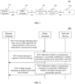
- FIG. 1 shows an example of a system framework according to the present disclosure.
- the system framework 100 may include a remote terminal 110, a relay terminal 120, an access network device 130, a core network device 140, and an Application Server (AS) 150.
- AS Application Server
- the remote terminal 110 and the relay terminal 120 may be terminal devices that have been authenticated via a network when in the coverage of the network.
- the remote terminal 110 may be a terminal device that is authenticated as being able to access the wireless network via a relay terminal.
- the remote terminal 110 may be authorized to serve as a remote User Equipment (Remote UE).
- the relay terminal 120 may be a terminal device authenticated being able to serve as a relay node. Both the remote terminal 110 and the relay terminal 120 may be authorized to transmit and receive relay discovery related messages, which may include a discovery message and a discovery request message.
- the remote terminal 110 and the relay terminal 120 may be any device or apparatus configured with a physical layer and a media access control layer.
- the terminal device may also be referred to as an access terminal, e.g., User Equipment (UE), subscriber unit, subscriber station, mobile, mobile station, remote station, remote terminal, mobile device, user terminal, terminal, wireless communication device, user agent, or user device.
- the access terminal may be a cellular phone, a cordless phone, a Session Initiation Protocol (SIP) phone, a Wireless Local Loop (WLL) station, a Personal Digital Assistant (PDA), a wireless communication-enabled handheld device or computing device, or any other linear processing device connected to a wireless modem, a vehicle mounted device, a wearable device, etc.
- SIP Session Initiation Protocol
- WLL Wireless Local Loop
- PDA Personal Digital Assistant
- the remote terminal 110 may support an end-to-end protocol stack, which may include a Packet Data Convergence Protocol (PDCP) layer of a 3GPP PC5 interface and upper protocol layers above the PDCP layer, including user plane protocol layers and control plane protocol layers.
- PDCP Packet Data Convergence Protocol
- the user plane protocol layers include, but not limited to, a Service Data Adaptation Protocol (SDAP) layer and an Internet Protocol (IP) layer
- the control plane protocol layers include, but not limited to, a Radio Resource Control (RRC) layer and a Non-Access Stratum (NAS).
- SDAP Service Data Adaptation Protocol
- IP Internet Protocol
- RRC Radio Resource Control
- NAS Non-Access Stratum
- the remote terminal 110 and the relay terminal 120 may support a point-to-point protocol stack, which may include Layer 2 (L2) and Layer 1 (L1) of the 3GPP PC5 interface.
- L2 and L2 protocol stack includes, but not limited to, a Radio Link Control (RLC) layer, a Media Access Control (MAC) layer and a physical (PHY) layer.
- RLC Radio Link Control
- MAC Media Access Control
- PHY physical
- the relay terminal 120 may be provided with a relay protocol layer.
- the functions of the relay protocol layer can be used to transmit data packets and related control information between remote terminals via the relay terminal.
- the relay protocol layer may be a terminal-to-network relay function based on Layer 3 relay, and Layer 3 is used to transfer control messages, including e.g., the Internet Protocol (IP) layer, the Radio Resource Control (RRC) layer, and the Non-Access Stratum (NAS). That is, a remote terminal accesses a network via a relay terminal with the Layer 3 relay function.
- the relay terminal has the function of IP layer relay.
- the relay terminal with the Layer 3 relay function can transmit data between the remote terminal and the network, and the remote terminal and the relay terminal can be connected via a sidelink.
- the relay protocol layer may be a terminal-to-network relay function based on Layer 3 relay, and Layer 2 is used to provide correct transmission and reception of signaling messages, including partial duplication detection.
- Layer 2 may include Media Access Control (MAC), Radio Link Control (RLC) and Physical (PHY) layers. That is, a remote terminal accesses a network via a relay terminal with the Layer 2 relay function.
- the relay terminal has the functions of the Access Stratum (AS) and the layers below the RLC layer. Similar to Rel-13 ProSe, the relay terminal with the Layer 2 relay function can transfer data between the remote terminal and the network, and the remote terminal and the relay terminal can be connected via a sidelink.
- AS Access Stratum
- the relay terminal with the Layer 2 relay function can transfer data between the remote terminal and the network, and the remote terminal and the relay terminal can be connected via a sidelink.
- the remote terminal (Remote UE) 110 can access the network device 130 via the relay terminal 120.
- the remote terminal 110 and the relay terminal 120 may be connected or communicated via a PC5 interface of the 3GPP system.
- the end-to-end connection or communication between the relay terminal 120 and the network device 130 may also be performed via a Uu interface of the 3GPP system.
- the remote terminal 110 or the relay terminal 120 may be referred to as a User Equipment (UE), an access terminal, a user unit, a user station, a mobile station, a remote station, a remote terminal, a mobile device, a user terminal, a terminal, a wireless communication device, a user agent, or a user device.
- UE User Equipment
- the terminal device may be a station (ST) in a WLAN, a cellular phone, a cordless phone, a Session Initiation Protocol (SIP) phone, a Wireless Local Loop (WLL) station, a Personal Digital Assistant (PDA) device, a handheld device or a computing device having a wireless communication function, another processing device connected to a wireless modem, a vehicle-mounted device, a wearable device, a terminal device in the next generation communication system (e.g., NR network), or a terminal device in a future evolved Public Land Mobile Network (PLMN), etc.
- ST station
- WLAN Wireless Local Loop
- PDA Personal Digital Assistant
- the remote terminal 110 or the relay terminal 120 may also be a wearable device.
- the wearable device also known as wearable smart device, is a general term for wearable devices that are intelligently designed and developed from everyday wear, such as glasses, gloves, watches, clothes, and shoes, by applying wearable technologies.
- a wearable device is a portable device that can be directly worn on or integrated into a user's clothes or accessories.
- a wearable device is not only a kind of hardware device, but can also provide powerful functions based on software support, data interaction, and cloud interaction.
- wearable smart devices may include full-featured, large-sized devices that can provide full or partial functions without relying on smart phones, such as smart watches or smart glasses, and devices that only focus on a certain type of application function and need to cooperate with other devices such as smart phones for use, such as various smart bracelets and smart jewelries for physical sign monitoring.
- the access network device may be a base station such as Evolutional Node (eNB or eNodeB) in an LTE system, a Next Generation Radio Access Network (NG RAN) device, a base station such as gNB in the NR system, or a radio controller in a Cloud Radio Access Network (CRAN), or the network device 120 may be a relay station, an access point, a vehicle-mounted device, a wearable device, a hub, a switch, a bridge, a router or a network device in a future evolved Public Land Mobile Network (PLMN).
- eNB Evolutional Node
- NG RAN Next Generation Radio Access Network
- CRAN Cloud Radio Access Network
- PLMN Public Land Mobile Network
- the core network device 140 may be a 5G Core (5GC) device, for example, Access and Mobility Management Function (AMF), Authentication Server Function (AUSF), User Plane Function (UPF), or Session Management Function (SMF).
- the core network device 130 may alternatively be an Evolved Packet Core (EPC) device of the LTE network, for example, a Session Management Function + Core Packet Gateway (SMF+PGW-C) device.
- EPC Evolved Packet Core
- SMF+PGW-C Session Management Function + Core Packet Gateway
- the SMF+PGW-C can implement the functions of both SMF and PGW-C.
- the above core network device may have other names, or a new network entity may be formed due to division of the functions of the core network, and the embodiment of the present disclosure is not limited to any of these examples.
- the remote terminal 110 can be connected to the relay terminal 120 via the PC5 interface, and the relay terminal 120 can be connected to the access network device 130 via the Uu interface, thereby being connected to the core network device 140, which is connected to the AS 150 via an N6 interface.
- the framework 100 may also be applicable to other 3GPP communication systems, such as the 4G communication system, or a future 3GPP communication system, and the present disclosure is not limited to this.
- the Application Server (AS) in FIG. 1 may also be another terminal device or an external public safety internet.
- a device having a communication function in a network/system may be referred to as a communication device.
- the communication devices may include the network device 120 and the terminal devices 110 with communication functions.
- the network device 120 and the terminal devices 110 may be the devices described above, and details thereof will be omitted here.
- the communication devices may also include other devices in the communication system 100, e.g., other network entities such as a network controller, an MME, etc., and the embodiment of the present disclosure is not limited to any of these examples.
- system and “network” may often be used interchangeably herein.
- the term “and/or” as used herein only represents a relationship between correlated objects, including three relationships.
- a and/or B may mean A only, B only, or both A and B.
- the symbol “/” as used herein represents an “or” relationship between the correlated objects preceding and succeeding the symbol.
- a specific relay function or relay service for the relay protocol layer of the relay terminal 120 i.e., the specific operation of the relay terminal, is designed. Accordingly, the operation efficiency and processing capability of the relay terminal can be improved without wasting the resources of the relay terminal.
- FIG. 2 is a schematic flowchart illustrating a wireless communication method 200 according to an embodiment of the present disclosure.
- the method 200 may be interactively executed by a remote terminal and a relay terminal.
- the remote terminal shown in FIG. 2 may be the remote terminal 110 shown in FIG. 1
- the relay terminal shown in FIG. 2 may be the relay terminal 120 shown in FIG. 1 .
- the method 200 may include the following.
- a remote terminal transmits to a relay terminal a first message indicating that a relay service mode required by the remote terminal is a first service mode and/or a second service mode.
- a relay terminal is enabled to determine the relay service mode required by the remote terminal, such that the relay terminal can provide a relay service for the remote terminal based on the first service mode or the second service mode indicated in the first message and the remote terminal can access a network via the relay terminal.
- the service mode of the relay terminal can be managed according to the service requirements of the remote terminal, such that the operation efficiency and processing capability of the relay terminal can be improved without wasting the resources of the relay terminal.
- the first service mode and the second service mode will be described below.
- the first service mode includes a service mode requiring forwarding of uplink data.
- the first service mode may include a service mode requiring forwarding of uplink data and downlink data.
- the first service mode may include a service mode requiring forwarding of uplink data but not downlink data.
- the first service mode may indicate that the remote terminal has been or is to be in a connected state.
- the first service mode may indicate that the remote terminal needs to establish a communication connection.
- the second service mode includes a service mode only used for forwarding a first downlink message.
- the second service mode may indicate that the remote terminal has been or is to be in an inactive state or an idle state.
- the first downlink message may include at least one of: a system message change message, an Earthquake and Tsunami Early Alert System (ETWS) message, a Commercial Mobile Alert Service (CMAS) message, or a paging message.
- a system message change message an Earthquake and Tsunami Early Alert System (ETWS) message, a Commercial Mobile Alert Service (CMAS) message, or a paging message.
- ETWS Earthquake and Tsunami Early Alert System
- CMAS Commercial Mobile Alert Service
- the second transceiving mode may include at least one of: information indicating that the remote terminal needs to receive second downlink message, identity information of the remote terminal, or information on a paging cycle of the remote terminal.
- the second downlink message may include at least one of: a system message change message, an ETWS message, a CMAS message, or a paging message.
- the second service mode may include at least one of:
- the method 200 may further include the following.
- the relay terminal determines whether a communication connection is successfully established or whether a downlink message can be successfully received.
- the relay terminal if it does not establish a communication connection with the network device, it is checked whether the attempt to establish the communication connection is successful.
- the communication connection may include, but not limited to, a radio bearer core network bearer, and/or a PDU session/connection, or the like.
- the relay terminal checks whether the required downlink message can be successfully received, for example, whether a common search space is configured on an active BWP, or whether the relay terminal is restrained from receiving the downlink message due to sidelink and/or downlink interference on relevant time resources.
- the method 200 may further include the following.
- the remote terminal receives a second message transmitted by the relay terminal in response to the first message.
- the first message may indicate that the relay service mode required by the remote terminal is the first service mode
- the second message may indicate whether a communication connection is successfully established between the relay terminal and a network device.
- the first message may indicate that the relay service mode required by the remote terminal is the first service mode
- the second message may be transmitted after a communication connection is successfully established between the relay terminal and a network device.
- the communication connection may include at least one of: a radio bearer connection, a core network bearer connection, or a Protocol Data Unit (PDU) session connection.
- PDU Protocol Data Unit
- the first message may indicate that the relay service mode required by the remote terminal is the second service mode, and the second message may indicate whether the relay terminal is capable of successfully receiving a downlink message.
- the first message may indicate that the relay service mode required by the remote terminal is the second service mode, and the second message may be transmitted when the relay terminal is capable of successfully receiving a downlink message.
- the relay terminal being capable of successfully receiving the downlink message may include at least one of: the relay terminal being configured with a common search space on an active Bandwidth Part (BWP), or the relay terminal not being restrained from receiving the downlink message due to sidelink and/or downlink interference.
- BWP Bandwidth Part
- the second message may indicate that the relay terminal is not capable of successfully receiving a downlink message.
- the second message may further instruct the remote terminal to disconnect or update a connection.
- the second message may only indicate that the relay terminal is not capable of successfully receiving the downlink message.
- the second message may indicate that the relay terminal is not capable of successfully receiving the downlink message, and instruct the remote terminal to disconnect or update the connection.
- the second message may be a first PC5-S message.
- the first PC5-S message may be a connection establishment/modification success message; or the first PC5-S message may be a connection establishment/modification rejection message.
- the second message may be a first PC5-Radio Resource Control (RRC) message.
- the first PC5-RRC message may include at least one of: a response message for a message requesting a relay service, a response message for configuration signaling of a sidelink bearer for Uu data, or a response message for signaling for requesting a downlink message.
- the sidelink bearer for Uu data may be Uu SRB 0/1/2.
- the downlink message requested by the signaling for requesting the downlink message may include, but not limited to, a system message change message, an ETWS message, a CMAS message, or a paging message.
- the downlink message requested by the signaling for requesting the downlink message may be a Paging Control Channel (PCCH) or a Broadcast Control Channel (BCCH).
- PCCH Paging Control Channel
- BCCH Broadcast Control Channel
- the method 200 may further include the following.
- the remote terminal receives an update message transmitted by the relay terminal, and the update message indicates an updated state of the relay terminal.
- the update message may include a cause for interruption of a communication connection between the relay terminal and a network device, or information on a cell to which the communication connection is restored.
- the information on the cell may be information on a cell identity.
- the cause for the interruption of the communication connection may include at least one of: a link failure, the relay terminal configured with no common search space in an active Bandwidth Part (BWP), or the relay terminal restrained from receiving a downlink message due to sidelink and/or downlink interference.
- BWP Bandwidth Part
- the method 200 may further include the following.
- the relay terminal determines whether the communication connection is successfully established or whether the downlink message can be successfully received.
- a communication connection has been established between the relay terminal and the network device, but a link failure scenario may occur, such as T304, T312, T310, or T307, multiple access failures, or a maximum number of Radio Link Control (RLC) retransmissions may be reached, etc.
- RLC Radio Link Control
- the relay terminal can transmit the update message to the remote terminal.
- the communication connection may include, but not limited to, a radio bearer, a core network bearer, and/or a PDU session/connection.
- the update message may include the cause for the interruption of the communication connection between the relay terminal and the network device, such as a scenario of link failure, such as T304, T312, T310, or T307, multiple access failures, or a maximum number of Radio Link Control (RLC) retransmissions may be reached, etc.
- a scenario of link failure such as T304, T312, T310, or T307
- multiple access failures such as multiple access failures
- RLC Radio Link Control
- the relay terminal may check whether the required downlink message can be successfully received, for example, whether a common search space is configured on an active BWP, or whether the relay terminal is restrained from receiving the downlink message due to sidelink and/or downlink interference on relevant time resources.
- the relay terminal may also transmit the update message to the remote terminal to indicate the restoration of the communication connection and/or information on the cell for which the communication connection is restored.
- the update message may be a second PC5-S message.
- the second PC5-S message may be a connection interruption/modification message.
- the update message may be a second PC5-RRC message.
- the second PC5-RRC message may include at least one of: a response message for a message requesting a relay service, a response message for configuration signaling of a sidelink bearer for Uu data, or a response message for signaling for requesting a downlink message.
- the sidelink bearer for Uu data may be Uu SRB 0/1/2.
- the downlink message requested by the signaling for requesting the downlink message may include, but not limited to, a system message change message, an ETWS message, a CMAS message, or a paging message.
- the downlink message requested by the signaling for requesting the downlink message may be a Paging Control Channel (PCCH) or a Broadcast Control Channel (BCCH).
- PCCH Paging Control Channel
- BCCH Broadcast Control Channel
- the first message may be a third PC5-S message.
- the third PC5-S message may be a connection establishment request/modification message.
- the remote terminal can indicate the relay service required by the relay terminal via the connection establishment request/modification information, for example, whether to provide a communication connection or to receive a paging message.
- the first message may be a third PC5-RRC message or a Uu-RRC message.
- the third PC5-RRC message may include at least one of: a message for requesting a relay service, configuration signaling of a sidelink bearer for Uu data, or signaling for requesting a downlink message.
- the first message may include at least one of: an RRC connection establishment/restoration/reestablishment message, a Protocol Data Unit (PDU) / Service Data Unit (SDU) on a sidelink bearer for Uu data, or a PDU/SDU on a sidelink bearer for a downlink message.
- PDU Protocol Data Unit
- SDU Service Data Unit
- the sidelink bearer for Uu data may be Uu SRB 0/1/2.
- the downlink message requested by the signaling for requesting the downlink message may include, but not limited to, a system message change message, an ETWS message, a CMAS message, or a paging message.
- the downlink message requested by the signaling for requesting the downlink message may be a Paging Control Channel (PCCH) or a Broadcast Control Channel (BCCH).
- PCCH Paging Control Channel
- BCCH Broadcast Control Channel
- the relay terminal can decide whether to establish a radio bearer with a network device based on the relay service required by the remote terminal. For example, when a communication connection is required, if the relay terminal successfully establishes the connection with the network device, it will reply with a connection establishment/modification success message, otherwise it will reply with a connection establishment/modification rejection message. In another example, if the network connection of the relay terminal is interrupted during the communication process, the relay terminal may notify the remote terminal to disconnect or modify the connection. In the case where a paging message needs to be received, if the relay terminal can successfully receive the paging message, it will reply with a connection establishment/modification success message, otherwise it will reply with a connection establishment/modification rejection message.
- the relay terminal can notify the remote terminal to disconnect or update the connection.
- the service mode of the relay terminal can be managed according to the service requirements of the remote terminal, and accordingly, the operation efficiency and processing capability of the relay terminal can be improved without wasting the resources of the relay terminal.
- the PC5-S message as used in the present disclosure may be a sidelink message transmitted via the PC5 interface
- the PC5-RRC message may be an RRC message transmitted via the PC5 interface
- the various types of interfaces as used in the present disclosure may be the interfaces specified in the 3GPP.
- the PC5 interface can be used to transmit data between the terminals
- the Uu interface can be used to transmit data between the terminal and the access network device.
- the terms “downlink” and “uplink” are used to indicate the transmission direction of signals or data.
- “downlink” is used to indicate that the transmission direction of signals or data is a first direction from a station to a user equipment of a cell
- “uplink” is used to indicate that the transmission direction of signals or data is a second direction from a user equipment in a cell to a station.
- a "downlink signal” indicates that the transmission direction of the signal is the first direction.
- the term “and/or” as used herein only represents a relationship between correlated objects, including three relationships.
- “A and/or B” may mean A only, B only, or both A and B.
- the symbol “/” as used herein represents an “or” relationship between the correlated objects preceding and succeeding the symbol.
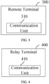
- FIG. 3 is a schematic block diagram of a remote terminal 300 according to an embodiment of the present disclosure.
- the remote terminal 300 may include: a communication unit 310 configured to transmit a first message indicating that a relay service mode required by the remote terminal is a first service mode and/or a second service mode.
- the first service includes service mode requiring forwarding of uplink data.
- the first service mode may indicate that the remote terminal has been or is to be in a connected state.
- the second service mode includes a service mode only used for forwarding a first downlink message.
- the second service mode may indicate that the remote terminal has been or is to be in an inactive state or an idle state.
- the first downlink message may include at least one of: a system message change message, an Earthquake and Tsunami Early Alert System (ETWS) message, a Commercial Mobile Alert Service (CMAS) message, or a paging message.
- a system message change message an Earthquake and Tsunami Early Alert System (ETWS) message, a Commercial Mobile Alert Service (CMAS) message, or a paging message.
- ETWS Earthquake and Tsunami Early Alert System
- CMAS Commercial Mobile Alert Service
- the second transceiving mode may include at least one of: information indicating that the remote terminal needs to receive second downlink message, identity information of the remote terminal, or information on a paging cycle of the remote terminal.
- the second downlink message may include at least one of: a system message change message, an Earthquake and Tsunami Early Alert System (ETWS) message, a Commercial Mobile Alert Service (CMAS) message, or a paging message.
- a system message change message an Earthquake and Tsunami Early Alert System (ETWS) message, a Commercial Mobile Alert Service (CMAS) message, or a paging message.
- ETWS Earthquake and Tsunami Early Alert System
- CMAS Commercial Mobile Alert Service
- the communication unit 310 may be further configured to: receive a second message as a response to the first message.
- the first message may indicate that the relay service mode required by the remote terminal is the first service mode
- the second message may indicate whether a communication connection is successfully established between the relay terminal and a network device.
- the first message may indicate that the relay service mode required by the remote terminal is the first service mode
- the second message may be transmitted after a communication connection is successfully established between the relay terminal and a network device.
- the communication connection may include at least one of: a radio bearer connection, a core network bearer connection, or a Protocol Data Unit (PDU) session connection.
- a radio bearer connection may include at least one of: a radio bearer connection, a core network bearer connection, or a Protocol Data Unit (PDU) session connection.
- PDU Protocol Data Unit
- the first message may indicate that the relay service mode required by the remote terminal is the second service mode
- the second message may indicate whether the relay terminal is capable of successfully receiving a downlink message
- the first message may indicate that the relay service mode required by the remote terminal is the second service mode, and the second message may be transmitted when the relay terminal is capable of successfully receiving a downlink message.
- the relay terminal being capable of successfully receiving the downlink message may include at least one of: the relay terminal being configured with a common search space on an active Bandwidth Part (BWP), or the relay terminal not being restrained from receiving the downlink message due to sidelink and/or downlink interference.
- BWP Bandwidth Part
- the second message may indicate that the relay terminal is not capable of successfully receiving a downlink message.
- the second message may further instruct the remote terminal to disconnect or update a connection.
- the second message may be a first PC5-S message.
- the first PC5-S message may be a connection establishment/modification success message; or the first PC5-S message may be a connection establishment/modification rejection message.
- the second message may be a first PC5-Radio Resource Control (RRC) message.
- RRC Radio Resource Control
- the first PC5-RRC message may include at least one of: a response message for a message requesting a relay service, a response message for configuration signaling of a sidelink bearer for Uu data, or a response message for signaling for requesting a downlink message.
- the communication unit 310 may be further configured to: receive an update message indicating an updated state of the relay terminal.
- the update message may include a cause for interruption of a communication connection between the relay terminal and a network device, or information on a cell to which the communication connection is restored.
- the cause for the interruption of the communication connection may include at least one of: a link failure, the relay terminal configured with no common search space in an active Bandwidth Part (BWP), or the relay terminal restrained from receiving a downlink message due to sidelink and/or downlink interference.
- BWP Bandwidth Part
- the update message may be a second PC5-S message.
- the second PC5-S message may be a connection interruption/modification message.
- the update message may be a second PC5-Radio Resource Control (RRC) message.
- RRC Radio Resource Control
- the second PC5-RRC message may include at least one of: a response message for a message requesting a relay service, a response message for configuration signaling of a sidelink bearer for Uu data, or a response message for signaling for requesting a downlink message.
- the first message may be a third PC5-S message.
- the third PC5-S message may be a connection establishment request/modification message.
- the first message may be a third PC5-RRC message or a Uu-RRC message.
- the third PC5-RRC message may include at least one of: a message for requesting a relay service, configuration signaling of a sidelink bearer for Uu data, or signaling for requesting a downlink message.
- the first message may include at least one of: an RRC connection establishment/restoration/reestablishment message, a Protocol Data Unit (PDU) / Service Data Unit (SDU) on a sidelink bearer for Uu data, or a PDU/SDU on a sidelink bearer for a downlink message.
- PDU Protocol Data Unit
- SDU Service Data Unit
- the apparatus embodiments and the method embodiments may correspond to each other, and for similar descriptions, reference can be made to the method embodiments.
- the remote terminal 300 as shown in FIG. 3 may corresponding to the corresponding entity for performing the method 200 according to the embodiment of the present disclosure, and the above and other operations and/or functions of the respective units in the remote terminal 300 are provided for implementing the corresponding processes in the respective methods in FIG. 2 .
- details thereof will be omitted here.
- FIG. 4 is a schematic block diagram of a relay terminal 400 according to an embodiment of the present disclosure.
- the relay terminal 400 may include: a communication unit 410 configured to receive a first message indicating that a relay service mode required by a remote terminal is a first service mode and/or a second service mode.
- the first service mode may include a service mode for communication connection and/or a service mode requiring forwarding of uplink data.
- the first service mode may indicate that the remote terminal has been or is to be in a connected state.
- the second service mode may include a service mode not used for communication connection and/or a service mode only used for forwarding a first downlink message.
- the second service mode may indicate that the remote terminal has been or is to be in an inactive state or an idle state.
- the first downlink message may include at least one of: a system message change message, an Earthquake and Tsunami Early Alert System (ETWS) message, a Commercial Mobile Alert Service (CMAS) message, or a paging message.
- a system message change message an Earthquake and Tsunami Early Alert System (ETWS) message, a Commercial Mobile Alert Service (CMAS) message, or a paging message.
- ETWS Earthquake and Tsunami Early Alert System
- CMAS Commercial Mobile Alert Service
- the second transceiving mode may include at least one of: information indicating that the remote terminal needs to receive second downlink message, identity information of the remote terminal, or information on a paging cycle of the remote terminal.
- the second downlink message may include at least one of: a system message change message, an Earthquake and Tsunami Early Alert System (ETWS) message, a Commercial Mobile Alert Service (CMAS) message, or a paging message.
- a system message change message an Earthquake and Tsunami Early Alert System (ETWS) message, a Commercial Mobile Alert Service (CMAS) message, or a paging message.
- ETWS Earthquake and Tsunami Early Alert System
- CMAS Commercial Mobile Alert Service
- the communication unit 410 may be further configured to: transmit a second message in response to the first message.
- the first message may indicate that the relay service mode required by the remote terminal is the first service mode
- the second message may indicate whether a communication connection is successfully established between the relay terminal and a network device.
- the first message may indicate that the relay service mode required by the remote terminal is the first service mode
- the second message may be transmitted after a communication connection is successfully established between the relay terminal and a network device.
- the communication connection may include at least one of: a radio bearer connection, a core network bearer connection, or a Protocol Data Unit (PDU) session connection.
- a radio bearer connection may include at least one of: a radio bearer connection, a core network bearer connection, or a Protocol Data Unit (PDU) session connection.
- PDU Protocol Data Unit
- the first message may indicate that the relay service mode required by the remote terminal is the second service mode
- the second message may indicate whether the relay terminal is capable of successfully receiving a downlink message
- the first message may indicate that the relay service mode required by the remote terminal is the second service mode, and the second message may be transmitted when the relay terminal is capable of successfully receiving a downlink message.
- the relay terminal being capable of successfully receiving the downlink message may include at least one of: the relay terminal being configured with a common search space on an active Bandwidth Part (BWP), or the relay terminal not being restrained from receiving the downlink message due to sidelink and/or downlink interference.
- BWP Bandwidth Part
- the second message may indicate that the relay terminal is not capable of successfully receiving a downlink message.
- the second message may further instruct the remote terminal to disconnect or update a connection.
- the second message may be a first PC5-S message.
- the first PC5-S message may be a connection establishment/modification success message; or, the first PC5-S message may be a connection establishment/modification rejection message.
- the second message may be a first PC5-Radio Resource Control (RRC) message.
- RRC Radio Resource Control
- the first PC5-RRC message may include at least one of: a response message for a message requesting a relay service, a response message for configuration signaling of a sidelink bearer for Uu data, or a response message for signaling for requesting a downlink message.
- the communication unit 410 may be further configured to: transmit an update message indicating an updated state of the relay terminal.
- the update message may include a cause for interruption of a communication connection between the relay terminal and a network device, or information on a cell to which the communication connection is restored.
- the cause for the interruption of the communication connection may include at least one of: a link failure, the relay terminal configured with no common search space in an active Bandwidth Part (BWP), or the relay terminal restrained from receiving a downlink message due to sidelink and/or downlink interference.
- BWP Bandwidth Part
- the update message may be a second PC5-S message.
- the second PC5-S message may be a connection interruption/modification message.
- the update message may be a second PC5-Radio Resource Control (RRC) message.
- RRC Radio Resource Control
- the second PC5-RRC message may include at least one of: a response message for a message requesting a relay service, a response message for configuration signaling of a sidelink bearer for Uu data, or a response message for signaling for requesting a downlink message.
- the first message may be a third PC5-S message.
- the third PC5-S message may be a connection establishment request/modification message.
- the first message may be a third PC5-RRC message or a Uu-RRC message.
- the third PC5-RRC message may include at least one of: a message for requesting a relay service, configuration signaling of a sidelink bearer for Uu data, or signaling for requesting a downlink message.
- the first message may include at least one of: an RRC connection establishment/restoration/reestablishment message, a Protocol Data Unit (PDU) / Service Data Unit (SDU) on a sidelink bearer for Uu data, or a PDU/SDU on a sidelink bearer for a downlink message.
- PDU Protocol Data Unit
- SDU Service Data Unit
- the apparatus embodiments and the method embodiments may correspond to each other, and for similar descriptions, reference can be made to the method embodiments.
- the relay terminal 400 as shown in FIG. 4 may corresponding to the corresponding entity for performing the method 200 according to the embodiment of the present disclosure, and the above and other operations and/or functions of the respective units in the relay terminal 400 are provided for implementing the corresponding processes in the respective methods in FIG. 2 .
- details thereof will be omitted here.
- the steps of the method embodiments in the embodiments of the present disclosure may be implemented by hardware integrated logic circuits in the processor and/or software instructions, and the steps of the methods disclosed in conjunction with the embodiments of the present disclosure may be directly embodied as implemented by a hardware decoding processor or a combination of hardware and software modules in a decoding processor.
- the software modules may be located in a random access memory, a flash memory, a read-only memory, a programmable read-only memory, an electrically erasable programmable memory, a register, and other storage media known in the art.
- the storage medium is located in the memory, and the processor reads the information in the memory, and performs the steps in the above method embodiments in combination with its hardware.
- processing unit and the communication unit above may be implemented by a processor and a transceiver, respectively.
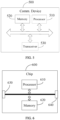
- FIG. 5 is a schematic diagram showing a structure of a communication device 500 according to an embodiment of the present disclosure.
- the communication device 500 includes a processor 510.
- the processor 510 can invoke and execute a computer program from a memory to implement the method according to the embodiment of the present disclosure.
- the communication device 500 may further include a memory 520.
- the memory 520 may be configured to store indication information, and may further be configured to store codes, instructions, etc. to be executed by the processor 510.
- the processor 510 can invoke and execute a computer program from the memory 520 to implement the method according to the embodiment of the present disclosure.
- the memory 520 may be a separate device independent from the processor 510, or may be integrated in the processor 810.
- the communication device 500 may further include a transceiver 530.
- the processor 510 may control the transceiver 530 to communicate with other devices, and in particular, transmit information or data to other devices, or receive information or data transmitted by other devices.
- the transceiver 530 may include a transmitter and a receiver.
- the transceiver 530 may further include one or more antennas.
- the components in the communication device 500 may be connected via a bus system.
- the bus system may include a power bus, a control bus and a status signal bus, in addition to a data bus.
- the communication device 500 may be the terminal device according to the embodiment of the present disclosure, and the communication device 500 may implement the corresponding processes implemented by the remote terminal in any of the methods according to the embodiments of the present disclosure. That is, the communication device 500 in the embodiment of the present disclosure may correspond to the remote terminal in the embodiment of the present disclosure, and may correspond to the corresponding entity that performs the method 200 according to the embodiment of the present disclosure. For the sake of brevity, details thereof will be omitted here. Similarly, the communication device 500 may be the network device according to the embodiment of the present disclosure, and the communication device 500 may implement the corresponding processes implemented by the relay terminal in any of the methods according to the embodiments of the present disclosure.
- the communication device 500 in the embodiment of the present disclosure may correspond to the relay terminal in the embodiment of the present disclosure, and may correspond to the corresponding entity that performs the method 200 according to the embodiment of the present disclosure.
- the communication device 500 in the embodiment of the present disclosure may correspond to the relay terminal in the embodiment of the present disclosure, and may correspond to the corresponding entity that performs the method 200 according to the embodiment of the present disclosure.
- details thereof will be omitted here.
- an embodiment of the present disclosure also provides a chip.
- the chip may be an integrated circuit chip, which has a signal processing capability, and can implement or perform any of the methods, steps, and logic block diagrams disclosed in the embodiments of the present disclosure.
- the chip may also be referred to as a system level chip, a system chip, a chip system, a system-on-a-chip, or the like.
- the chip can be applied in various communication devices, such that the communication device installed with the chip can perform the methods, steps and logic block diagrams disclosed in the embodiments of the present disclosure.
- FIG. 6 is a schematic diagram showing a structure of a chip 600 according to an embodiment of the present disclosure.
- the chip 600 includes a processor 610.
- the processor 610 can invoke and execute a computer program from a memory to implement the method according to the embodiment of the present disclosure.
- the chip 600 may further include a memory 620.
- the processor 610 can invoke and execute a computer program from the memory 620 to implement the method according to the embodiment of the present disclosure.
- the memory 620 may be configured to store indication information, and may further be configured to store codes, instructions, etc. to be executed by the processor 610.
- the memory 620 may be a separate device independent from the processor 610, or may be integrated in the processor 910.
- the chip 600 may further include an input interface 630.
- the processor 610 can control the input interface 630 to communicate with other devices or chips, and in particular, obtain information or data transmitted by other devices or chips.
- the chip 600 may further include an output interface 640.
- the processor 610 can control the output interface 640 to communicate with other devices or chips, and in particular, output information or data to other devices or chips.
- the chip 600 may be applied in the remote terminal according to the embodiment of the present disclosure, and the chip 600 may implement the corresponding processes implemented by the relay terminal in any of the methods according to the embodiments of the present disclosure, or the corresponding processes implemented by the relay terminal in any of the methods according to the embodiments of the present disclosure.
- the chip 600 may be applied in the remote terminal according to the embodiment of the present disclosure, and the chip 600 may implement the corresponding processes implemented by the relay terminal in any of the methods according to the embodiments of the present disclosure, or the corresponding processes implemented by the relay terminal in any of the methods according to the embodiments of the present disclosure.
- details thereof will be omitted here.
- the components in the chip 600 may be connected via a bus system.
- the bus system may include a power bus, a control bus and a status signal bus, in addition to a data bus.
- the above processor may include, but not limited to, a general purpose processor, a Digital Signal Processor (DSP), an Application Specific Integrated Circuit (ASIC), a Field Programmable Gate Array (FPGA) or another programmable logic device, a discrete gate or transistor logic device, or a discrete hardware component.
- DSP Digital Signal Processor
- ASIC Application Specific Integrated Circuit
- FPGA Field Programmable Gate Array
- the methods, steps, and logical block diagrams disclosed in the embodiments of the present disclosure can be implemented or performed by the processor.
- the general purpose processor may be a microprocessor or any conventional processor.
- the steps of the methods disclosed in the embodiments of the present disclosure may be directly embodied as being performed and completed by a hardware decoding processor, or by a combination of hardware and software modules in the decoding processor.
- the software modules can be located in a known storage medium in the related art, such as random access memory, flash memory, read-only memory, programmable read-only memory, erasable programmable memory, or register.
- the storage medium can be located in the memory, and the processor can read information from the memory and perform the steps of the above methods in combination with its hardware.
- the above memory may include, but not limited to, a volatile memory and/or a non-volatile memory.
- the non-volatile memory may be a Read-Only Memory (ROM), a Programmable ROM (PROM), an Erasable PROM (EPROM), an Electrically EPROM (EEPROM), or a flash memory.
- the volatile memory may be a Random Access Memory (RAM), which is used as an external cache.
- RAM Random Access Memory
- many forms of RAMs are available, including Static RAM (SRAM), Dynamic RAM (DRAM), Synchronous DRAM (SDRAM), Double Data Rate SDRAM (DDR SDRAM), Enhanced SDRAM (ESDRAM), Synchlink DRAM (SLDRAM)), and Direct Rambus RAM (DR RAM).
- An embodiment of the present disclosure also provides a computer readable storage medium for storing a computer program.
- the computer readable storage medium stores one or more programs including instructions which, when executed by a portable electronic device including a plurality of application programs, enable the portable electronic device to perform the method 200 according to any of the method embodiments.
- the computer readable storage medium can be applied to the network device in the embodiment of the present disclosure, and the computer program can cause a computer to perform corresponding procedures implemented by the network device in the method according to any of the embodiments of the present disclosure. Details thereof will be omitted here for simplicity.
- the computer readable storage medium can be applied to the mobile terminal/terminal device in the embodiment of the present disclosure, and the computer program can cause a computer to perform corresponding procedures implemented by the mobile terminal/terminal device in the method according to any of the embodiments of the present disclosure. Details thereof will be omitted here for simplicity.
- An embodiment of the present disclosure also provides a computer program product including a computer program.
- the computer program product can be applied to the network device in the embodiment of the present disclosure, and the computer program can cause a computer to perform corresponding procedures implemented by the network device in the method according to any of the embodiments of the present disclosure. Details thereof will be omitted here for simplicity.
- the computer program product can be applied to the mobile terminal/terminal device in the embodiment of the present disclosure, and the computer program can cause a computer to perform corresponding procedures implemented by the mobile terminal/terminal device in the method according to any of the embodiments of the present disclosure. Details thereof will be omitted here for simplicity.
- An embodiment of the present disclosure also provides a computer program which, when executed by a computer, causes the computer to perform the method 200 according to any of the method embodiments.
- the computer program can be applied to the network device in the embodiment of the present disclosure.
- the computer program when executed on a computer, can cause the computer to perform corresponding procedures implemented by the network device in the method according to any of the embodiments of the present disclosure. Details thereof will be omitted here for simplicity.
- an embodiment of the present disclosure further provides a communication system, which may include the above terminal device and network device to form the communication system 100 as shown in FIG. 1 . Details thereof will be omitted here for simplicity. It should be noted that the term “system” and the like as used herein may also be referred to as “network management architecture” or “network system” or the like.
- the computer software product may be stored in a storage medium and contain instructions to enable a computer device, such as a personal computer, a server, or a network device, etc., to perform all or part of the steps of the method described in the embodiments of the present disclosure.
- the storage medium may include a Universal Serial Bus flash drive, a mobile hard disk, a Read-Only Memory (ROM), a Random Access Memory (RAM), a magnetic disk, an optical disc, or any other medium capable of storing program codes.
- the divisions of the units or modules or components in the apparatus embodiments as described above are only divisions based on logical functions, and there may be other divisions in actual implementations.
- more than one unit or module or component may be combined or integrated into another system, or some units or modules or components can be ignored or omitted.
- the units/modules/components described above as separate/explicit components may or may not be physically separated, that is, they may be co-located or distributed across a number of network elements. Some or all of the units/modules/components may be selected according to actual needs to achieve the objects of the embodiments of the present disclosure.
- mutual coupling or direct coupling or communicative connection as shown or discussed above may be indirect coupling or communicative connection between devices or units via some interfaces which may be electrical, mechanical, or in any other forms.
Landscapes
- Engineering & Computer Science (AREA)
- Computer Networks & Wireless Communication (AREA)
- Signal Processing (AREA)
- Mobile Radio Communication Systems (AREA)
Claims (10)
- Drahtloskommunikationsverfahren, das von einem entfernten Endgerät durchgeführt wird, umfassend:Senden (S210), durch das entfernte Endgerät an ein Relais-Endgerät, einer ersten Nachricht, die anzeigt, dass ein vom entfernten Endgerät angeforderter Relais-Dienstmodus ein erster Dienstmodus und/oder ein zweiter Dienstmodus ist; undEmpfangen (S230), durch das entfernte Endgerät vom Relais-Endgerät, einer zweiten Nachricht als Antwort auf die erste Nachricht,wobeider erste Dienstmodus einen Dienstmodus umfasst, der das Weiterleiten von Uplink-Daten erfordert,der zweite Dienstmodus einen Dienstmodus umfasst, der nur zum Weiterleiten einer ersten Downlink-Nachricht verwendet wird,die erste Downlink-Nachricht eine Paging-Nachricht umfasst,wobei die zweite Nachricht eine erste PC5-"Radio Resource Control"-, -RRC-, Nachricht ist,die erste PC5-RRC-Nachricht eine Antwortnachricht zur Beantwortung einer Signalisierung zur Anforderung einer Downlink-Nachricht umfasst.
- Verfahren nach Anspruch 1, wobei der zweite Dienstmodus mindestens eines von Identitätsinformationen des entfernten Endgeräts oder Informationen über einen Paging-Zyklus des entfernten Endgeräts umfasst.
- Verfahren nach einem der Ansprüche 1 bis 2, ferner umfassend:
Empfangen (S250), durch das entfernte Endgerät, einer Aktualisierungsnachricht, die einen aktualisierten Zustand des Relais-Endgeräts anzeigt. - Verfahren nach Anspruch 3, wobei die Aktualisierungsnachricht eine Ursache für die Unterbrechung einer Kommunikationsverbindung zwischen dem Relais-Endgerät und einer Netzvorrichtung beinhaltet,
die Ursache für die Unterbrechung der Kommunikationsverbindung einen Verbindungsausfall umfasst. - Verfahren nach Anspruch 3 oder 4, wobei die Aktualisierungsnachricht eine zweite PC5-"Radio Resource Control"-, -RRC-, Nachricht ist.
- Verfahren nach einem der Ansprüche 1 bis 5, wobei die erste Nachricht eine dritte PC5-RRC-Nachricht ist, die dritte PC5-RRC-Nachricht eine Signalisierung zur Anforderung einer Downlink-Nachricht umfasst.
- Verfahren nach einem der Ansprüche 1 bis 4, wobei die erste Nachricht eine "Protocol Data Unit", PDU, / "Service Data Unit", SDU, auf einem Sidelink-Träger für Uu-Daten umfasst, wobei der Sidelink-Träger für Uu-Daten Uu SRB 0/1/2 ist.
- Drahtloskommunikationsverfahren, das von einem Relais-Endgerät durchgeführt wird, umfassend: Empfangen, durch das Relais-Endgerät von einem entfernten Endgerät, einer ersten Nachricht, die anzeigt, dass ein vom entfernten Endgerät angeforderter Relais-Dienstmodus ein erster Dienstmodus und/oder ein zweiter Dienstmodus ist; Bestimmen, durch das Relais-Endgerät auf der Grundlage der ersten Nachricht, ob eine Kommunikationsverbindung erfolgreich aufgebaut wurde oder ob eine Downlink-Nachricht erfolgreich empfangen wurde; undSenden, durch das Relais-Endgerät an das entfernte Endgerät, einer zweiten Nachricht als Antwort auf die erste Nachricht,wobeider erste Dienstmodus einen Dienstmodus umfasst, der das Weiterleiten von Uplink-Daten erfordert,der zweite Dienstmodus einen Dienstmodus umfasst, der nur zum Weiterleiten einer ersten Downlink-Nachricht verwendet wird,die erste Downlink-Nachricht eine Paging-Nachricht umfasst,wobei die zweite Nachricht eine erste PC5-"Radio Resource Control"-, -RRC-, Nachricht ist,die erste PC5-RRC-Nachricht eine Antwortnachricht zur Beantwortung einer Signalisierung zur Anforderung einer Downlink-Nachricht umfasst.
- Entferntes Endgerät, umfassend einen Prozessor (510), einen Speicher (520) und einen Sender-Empfänger (530), wobei der Speicher (520) dafür ausgelegt ist, ein Computerprogramm zu speichern, und der Prozessor (510) dafür ausgelegt ist, zum Durchführen des Verfahrens nach einem der Ansprüche 1 bis 7 das im Speicher (520) gespeicherte Computerprogramm aufzurufen und auszuführen.
- Relais-Endgerät, umfassend einen Prozessor (510), einen Speicher (520) und einen Sender-Empfänger (530), wobei der Speicher (520) dafür ausgelegt ist, ein Computerprogramm zu speichern, und der Prozessor (510) dafür ausgelegt ist, zum Durchführen des Verfahrens nach Anspruch 8 das im Speicher (520) gespeicherte Computerprogramm aufzurufen und auszuführen.
Applications Claiming Priority (1)
| Application Number | Priority Date | Filing Date | Title |
|---|---|---|---|
| PCT/CN2020/109330 WO2022032672A1 (zh) | 2020-08-14 | 2020-08-14 | 无线通信方法和终端 |
Publications (3)
| Publication Number | Publication Date |
|---|---|
| EP4199643A1 EP4199643A1 (de) | 2023-06-21 |
| EP4199643A4 EP4199643A4 (de) | 2023-08-16 |
| EP4199643B1 true EP4199643B1 (de) | 2025-05-14 |
Family
ID=80247570
Family Applications (1)
| Application Number | Title | Priority Date | Filing Date |
|---|---|---|---|
| EP20949170.3A Active EP4199643B1 (de) | 2020-08-14 | 2020-08-14 | Drahtloskommunikationsverfahren und endgerät |
Country Status (4)
| Country | Link |
|---|---|
| US (1) | US20230199712A1 (de) |
| EP (1) | EP4199643B1 (de) |
| CN (2) | CN115918255A (de) |
| WO (1) | WO2022032672A1 (de) |
Families Citing this family (2)
| Publication number | Priority date | Publication date | Assignee | Title |
|---|---|---|---|---|
| EP4233427A4 (de) * | 2020-10-22 | 2024-07-17 | Qualcomm Incorporated | Durch empfängerbenutzerausrüstung (ue) aktivierte sidelink-übertragungen |
| US12200788B1 (en) * | 2023-07-13 | 2025-01-14 | Asus Technology Licensing Inc. | Method and apparatus for relay UE adding source end UE for UE-to-UE relay communication in a wireless communication system |
Family Cites Families (17)
| Publication number | Priority date | Publication date | Assignee | Title |
|---|---|---|---|---|
| US8769023B2 (en) * | 2011-08-03 | 2014-07-01 | Juniper Networks, Inc. | Disaster response system |
| CN106162929B (zh) * | 2015-04-07 | 2021-08-06 | 中兴通讯股份有限公司 | 在设备直通系统中用户终端与中继节点的通信方法和装置 |
| WO2017039735A1 (en) * | 2015-09-03 | 2017-03-09 | Intel IP Corporation | User equipment, and evolved node bs supporting layer-2 relaying and route switching |
| US10609744B2 (en) * | 2015-10-22 | 2020-03-31 | Lg Electronics Inc. | Method for direct communication between terminals in wireless communication system and apparatus for method |
| JP6907221B2 (ja) * | 2016-02-05 | 2021-07-21 | 華為技術有限公司Huawei Technologies Co.,Ltd. | 通信リソース割当方法および装置、端末装置、基地局、ならびに通信システム |
| AR110030A1 (es) * | 2016-11-02 | 2019-02-13 | Ericsson Telefon Ab L M | Gestión de la movilidad para retransmisión |
| CN108377564B (zh) * | 2016-11-14 | 2023-05-30 | 中兴通讯股份有限公司 | 终端接入网络的方法及装置、下行数据投递方法及装置 |
| CN108207017B (zh) * | 2016-12-20 | 2019-09-17 | 电信科学技术研究院 | 一种处理寻呼的方法和装置 |
| WO2018143758A1 (ko) * | 2017-02-06 | 2018-08-09 | 엘지전자 주식회사 | 무선 통신 시스템에서 제1 ue와 연결을 가진 제2 ue의 페이징 관련 동작을 수행하는 방법 및 이를 위한 장치 |
| CN110393026B (zh) * | 2017-03-10 | 2023-05-12 | 索尼移动通讯有限公司 | 与无线通信网络建立连接的方法和与终端建立连接的方法 |
| CN110999397B (zh) * | 2017-08-11 | 2022-04-29 | 华为技术有限公司 | 一种设备发现方法及相关设备 |
| CN110098858A (zh) * | 2018-01-30 | 2019-08-06 | 电信科学技术研究院有限公司 | 一种中继工作模式配置方法及终端 |
| US11272526B2 (en) * | 2018-05-09 | 2022-03-08 | Qualcomm Incorporated | Efficient operation with unlicensed downlink (DL) and licensed uplink (UL) by transmission of selective DL messages using licensed UL |
| CN110557184B (zh) * | 2018-05-31 | 2021-11-16 | 阿里巴巴集团控股有限公司 | 一种基于中继设备的通信、终端与基站的通信方法和装置 |
| CN115190531B (zh) * | 2019-04-30 | 2025-10-03 | 华为技术有限公司 | 数据传输的方法和装置 |
| WO2021232362A1 (en) * | 2020-05-21 | 2021-11-25 | Mediatek Singapore Pte. Ltd. | Methods and apparatus of sidelink relay based data communication |
| CN113973284B (zh) * | 2020-07-24 | 2023-12-08 | 华为技术有限公司 | 侧行链路信令无线承载配置的方法和通信装置 |
-
2020
- 2020-08-14 WO PCT/CN2020/109330 patent/WO2022032672A1/zh not_active Ceased
- 2020-08-14 CN CN202080102476.XA patent/CN115918255A/zh active Pending
- 2020-08-14 EP EP20949170.3A patent/EP4199643B1/de active Active
- 2020-08-14 CN CN202311408455.2A patent/CN117412403A/zh active Pending
-
2022
- 2022-12-28 US US18/090,147 patent/US20230199712A1/en active Pending
Also Published As
| Publication number | Publication date |
|---|---|
| US20230199712A1 (en) | 2023-06-22 |
| EP4199643A4 (de) | 2023-08-16 |
| CN117412403A (zh) | 2024-01-16 |
| WO2022032672A1 (zh) | 2022-02-17 |
| EP4199643A1 (de) | 2023-06-21 |
| CN115918255A (zh) | 2023-04-04 |
Similar Documents
| Publication | Publication Date | Title |
|---|---|---|
| CN111787525A (zh) | 一种信息传输方法及装置、通信设备 | |
| CN115065988B (zh) | 中继传输的方法、中继终端和远端终端 | |
| CN116321489B (zh) | 中继发现方法和终端 | |
| CN113853809B (zh) | 用于处置ue类别信息的ue、网络节点 | |
| EP3952596A1 (de) | Informationsübertragungsverfahren und -einrichtung und netzwerkvorrichtung | |
| JP7213950B2 (ja) | 情報構成方法および装置、端末、ネットワーク機器 | |
| EP4145924B1 (de) | Funkrufoptimierungsverfahren und netzwerkvorrichtungen | |
| US20230199712A1 (en) | Wireless communication method and terminal | |
| CN116114315B (zh) | 无线通信的方法、终端设备和网络设备 | |
| CN115004848B (zh) | 无线通信方法和终端设备 | |
| EP4013184B1 (de) | Freigabe einer dedizierten funkverbindungskonfiguration in einer d2d-kommunikation | |
| CN116250290B (zh) | 无线通信方法、终端设备、第一接入网设备以及网元 | |
| CN116074847A (zh) | 一种信号传输方法及装置、终端设备 | |
| CN116114366B (zh) | 用于终端间通信的方法、终端设备和网络设备 | |
| CN114600552B (zh) | 一种通信方法、装置及设备 | |
| CN116261887B (zh) | 无线通信的方法、终端设备和网络设备 | |
| US20240137833A1 (en) | Wireless communication method, first terminal, and communication device | |
| KR20230049646A (ko) | 중계 통신 방법 및 디바이스 | |
| US12376170B2 (en) | Configuration reset method and apparatus, and terminal device | |
| CN114930971A (zh) | 一种配置信息的协商方法及装置、终端设备 | |
| CN116134912B (zh) | 一种通信方法及装置、网络设备、终端设备 | |
| CN116321490B (zh) | 数据传输方法、网络设备和终端设备 | |
| CN118044333A (zh) | 无线通信方法、第一终端以及网络设备 | |
| CN119096689A (zh) | 无线通信的方法、终端设备和网络设备 | |
| WO2025065633A1 (zh) | 信息接收和发送方法及其装置、通信系统 |
Legal Events
| Date | Code | Title | Description |
|---|---|---|---|
| STAA | Information on the status of an ep patent application or granted ep patent |
Free format text: STATUS: THE INTERNATIONAL PUBLICATION HAS BEEN MADE |
|
| PUAI | Public reference made under article 153(3) epc to a published international application that has entered the european phase |
Free format text: ORIGINAL CODE: 0009012 |
|
| STAA | Information on the status of an ep patent application or granted ep patent |
Free format text: STATUS: REQUEST FOR EXAMINATION WAS MADE |
|
| 17P | Request for examination filed |
Effective date: 20221228 |
|
| AK | Designated contracting states |
Kind code of ref document: A1 Designated state(s): AL AT BE BG CH CY CZ DE DK EE ES FI FR GB GR HR HU IE IS IT LI LT LU LV MC MK MT NL NO PL PT RO RS SE SI SK SM TR |
|
| A4 | Supplementary search report drawn up and despatched |
Effective date: 20230717 |
|
| RIC1 | Information provided on ipc code assigned before grant |
Ipc: H04W 88/04 20090101AFI20230711BHEP |
|
| DAV | Request for validation of the european patent (deleted) | ||
| DAX | Request for extension of the european patent (deleted) | ||
| STAA | Information on the status of an ep patent application or granted ep patent |
Free format text: STATUS: EXAMINATION IS IN PROGRESS |
|
| 17Q | First examination report despatched |
Effective date: 20240422 |
|
| REG | Reference to a national code |
Ref country code: DE Ref legal event code: R079 Free format text: PREVIOUS MAIN CLASS: H04W0088040000 Ipc: H04W0076140000 Ref country code: DE Ref legal event code: R079 Ref document number: 602020051460 Country of ref document: DE Free format text: PREVIOUS MAIN CLASS: H04W0088040000 Ipc: H04W0076140000 |
|
| GRAP | Despatch of communication of intention to grant a patent |
Free format text: ORIGINAL CODE: EPIDOSNIGR1 |
|
| RIC1 | Information provided on ipc code assigned before grant |
Ipc: H04W 88/04 20090101ALN20241114BHEP Ipc: H04W 76/14 20180101AFI20241114BHEP |
|
| STAA | Information on the status of an ep patent application or granted ep patent |
Free format text: STATUS: GRANT OF PATENT IS INTENDED |
|
| RIC1 | Information provided on ipc code assigned before grant |
Ipc: H04W 88/04 20090101ALN20241119BHEP Ipc: H04W 76/14 20180101AFI20241119BHEP |
|
| RIC1 | Information provided on ipc code assigned before grant |
Ipc: H04W 88/04 20090101ALN20241204BHEP Ipc: H04W 76/14 20180101AFI20241204BHEP |
|
| RIC1 | Information provided on ipc code assigned before grant |
Ipc: H04W 88/04 20090101ALN20241210BHEP Ipc: H04W 76/14 20180101AFI20241210BHEP |
|
| INTG | Intention to grant announced |
Effective date: 20241219 |
|
| GRAS | Grant fee paid |
Free format text: ORIGINAL CODE: EPIDOSNIGR3 |
|
| GRAA | (expected) grant |
Free format text: ORIGINAL CODE: 0009210 |
|
| STAA | Information on the status of an ep patent application or granted ep patent |
Free format text: STATUS: THE PATENT HAS BEEN GRANTED |
|
| AK | Designated contracting states |
Kind code of ref document: B1 Designated state(s): AL AT BE BG CH CY CZ DE DK EE ES FI FR GB GR HR HU IE IS IT LI LT LU LV MC MK MT NL NO PL PT RO RS SE SI SK SM TR |
|
| REG | Reference to a national code |
Ref country code: GB Ref legal event code: FG4D |
|
| REG | Reference to a national code |
Ref country code: CH Ref legal event code: EP |
|
| REG | Reference to a national code |
Ref country code: DE Ref legal event code: R096 Ref document number: 602020051460 Country of ref document: DE |
|
| REG | Reference to a national code |
Ref country code: IE Ref legal event code: FG4D |
|
| REG | Reference to a national code |
Ref country code: NL Ref legal event code: MP Effective date: 20250514 |
|
| P01 | Opt-out of the competence of the unified patent court (upc) registered |
Free format text: CASE NUMBER: UPC_APP_5346_4199643/2025 Effective date: 20250829 |
|
| PG25 | Lapsed in a contracting state [announced via postgrant information from national office to epo] |
Ref country code: PT Free format text: LAPSE BECAUSE OF FAILURE TO SUBMIT A TRANSLATION OF THE DESCRIPTION OR TO PAY THE FEE WITHIN THE PRESCRIBED TIME-LIMIT Effective date: 20250915 Ref country code: FI Free format text: LAPSE BECAUSE OF FAILURE TO SUBMIT A TRANSLATION OF THE DESCRIPTION OR TO PAY THE FEE WITHIN THE PRESCRIBED TIME-LIMIT Effective date: 20250514 Ref country code: ES Free format text: LAPSE BECAUSE OF FAILURE TO SUBMIT A TRANSLATION OF THE DESCRIPTION OR TO PAY THE FEE WITHIN THE PRESCRIBED TIME-LIMIT Effective date: 20250514 |
|
| PGFP | Annual fee paid to national office [announced via postgrant information from national office to epo] |
Ref country code: DE Payment date: 20250827 Year of fee payment: 6 |
|
| REG | Reference to a national code |
Ref country code: LT Ref legal event code: MG9D |
|
| PG25 | Lapsed in a contracting state [announced via postgrant information from national office to epo] |
Ref country code: NO Free format text: LAPSE BECAUSE OF FAILURE TO SUBMIT A TRANSLATION OF THE DESCRIPTION OR TO PAY THE FEE WITHIN THE PRESCRIBED TIME-LIMIT Effective date: 20250814 Ref country code: GR Free format text: LAPSE BECAUSE OF FAILURE TO SUBMIT A TRANSLATION OF THE DESCRIPTION OR TO PAY THE FEE WITHIN THE PRESCRIBED TIME-LIMIT Effective date: 20250815 |
|
| PG25 | Lapsed in a contracting state [announced via postgrant information from national office to epo] |
Ref country code: NL Free format text: LAPSE BECAUSE OF FAILURE TO SUBMIT A TRANSLATION OF THE DESCRIPTION OR TO PAY THE FEE WITHIN THE PRESCRIBED TIME-LIMIT Effective date: 20250514 Ref country code: PL Free format text: LAPSE BECAUSE OF FAILURE TO SUBMIT A TRANSLATION OF THE DESCRIPTION OR TO PAY THE FEE WITHIN THE PRESCRIBED TIME-LIMIT Effective date: 20250514 |
|
| REG | Reference to a national code |
Ref country code: AT Ref legal event code: MK05 Ref document number: 1795900 Country of ref document: AT Kind code of ref document: T Effective date: 20250514 |
|
| PG25 | Lapsed in a contracting state [announced via postgrant information from national office to epo] |
Ref country code: BG Free format text: LAPSE BECAUSE OF FAILURE TO SUBMIT A TRANSLATION OF THE DESCRIPTION OR TO PAY THE FEE WITHIN THE PRESCRIBED TIME-LIMIT Effective date: 20250514 |
|
| PGFP | Annual fee paid to national office [announced via postgrant information from national office to epo] |
Ref country code: GB Payment date: 20250826 Year of fee payment: 6 |
|
| PG25 | Lapsed in a contracting state [announced via postgrant information from national office to epo] |
Ref country code: HR Free format text: LAPSE BECAUSE OF FAILURE TO SUBMIT A TRANSLATION OF THE DESCRIPTION OR TO PAY THE FEE WITHIN THE PRESCRIBED TIME-LIMIT Effective date: 20250514 |
|
| PG25 | Lapsed in a contracting state [announced via postgrant information from national office to epo] |
Ref country code: AT Free format text: LAPSE BECAUSE OF FAILURE TO SUBMIT A TRANSLATION OF THE DESCRIPTION OR TO PAY THE FEE WITHIN THE PRESCRIBED TIME-LIMIT Effective date: 20250514 |
|
| PGFP | Annual fee paid to national office [announced via postgrant information from national office to epo] |
Ref country code: FR Payment date: 20250826 Year of fee payment: 6 |
|
| PG25 | Lapsed in a contracting state [announced via postgrant information from national office to epo] |
Ref country code: RS Free format text: LAPSE BECAUSE OF FAILURE TO SUBMIT A TRANSLATION OF THE DESCRIPTION OR TO PAY THE FEE WITHIN THE PRESCRIBED TIME-LIMIT Effective date: 20250814 |
|
| PG25 | Lapsed in a contracting state [announced via postgrant information from national office to epo] |
Ref country code: IS Free format text: LAPSE BECAUSE OF FAILURE TO SUBMIT A TRANSLATION OF THE DESCRIPTION OR TO PAY THE FEE WITHIN THE PRESCRIBED TIME-LIMIT Effective date: 20250914 |
|
| PG25 | Lapsed in a contracting state [announced via postgrant information from national office to epo] |
Ref country code: LV Free format text: LAPSE BECAUSE OF FAILURE TO SUBMIT A TRANSLATION OF THE DESCRIPTION OR TO PAY THE FEE WITHIN THE PRESCRIBED TIME-LIMIT Effective date: 20250514 |
|
| PG25 | Lapsed in a contracting state [announced via postgrant information from national office to epo] |
Ref country code: SM Free format text: LAPSE BECAUSE OF FAILURE TO SUBMIT A TRANSLATION OF THE DESCRIPTION OR TO PAY THE FEE WITHIN THE PRESCRIBED TIME-LIMIT Effective date: 20250514 Ref country code: DK Free format text: LAPSE BECAUSE OF FAILURE TO SUBMIT A TRANSLATION OF THE DESCRIPTION OR TO PAY THE FEE WITHIN THE PRESCRIBED TIME-LIMIT Effective date: 20250514 |
|
| PG25 | Lapsed in a contracting state [announced via postgrant information from national office to epo] |
Ref country code: CZ Free format text: LAPSE BECAUSE OF FAILURE TO SUBMIT A TRANSLATION OF THE DESCRIPTION OR TO PAY THE FEE WITHIN THE PRESCRIBED TIME-LIMIT Effective date: 20250514 |
|
| PG25 | Lapsed in a contracting state [announced via postgrant information from national office to epo] |
Ref country code: EE Free format text: LAPSE BECAUSE OF FAILURE TO SUBMIT A TRANSLATION OF THE DESCRIPTION OR TO PAY THE FEE WITHIN THE PRESCRIBED TIME-LIMIT Effective date: 20250514 |
|
| PG25 | Lapsed in a contracting state [announced via postgrant information from national office to epo] |
Ref country code: SK Free format text: LAPSE BECAUSE OF FAILURE TO SUBMIT A TRANSLATION OF THE DESCRIPTION OR TO PAY THE FEE WITHIN THE PRESCRIBED TIME-LIMIT Effective date: 20250514 |
|
| PG25 | Lapsed in a contracting state [announced via postgrant information from national office to epo] |
Ref country code: IT Free format text: LAPSE BECAUSE OF FAILURE TO SUBMIT A TRANSLATION OF THE DESCRIPTION OR TO PAY THE FEE WITHIN THE PRESCRIBED TIME-LIMIT Effective date: 20250514 |
|
| REG | Reference to a national code |
Ref country code: DE Ref legal event code: R097 Ref document number: 602020051460 Country of ref document: DE |
|
| PG25 | Lapsed in a contracting state [announced via postgrant information from national office to epo] |
Ref country code: RO Free format text: LAPSE BECAUSE OF FAILURE TO SUBMIT A TRANSLATION OF THE DESCRIPTION OR TO PAY THE FEE WITHIN THE PRESCRIBED TIME-LIMIT Effective date: 20250514 |
|
| PLBE | No opposition filed within time limit |
Free format text: ORIGINAL CODE: 0009261 |
|
| STAA | Information on the status of an ep patent application or granted ep patent |
Free format text: STATUS: NO OPPOSITION FILED WITHIN TIME LIMIT |
|
| REG | Reference to a national code |
Ref country code: CH Ref legal event code: H13 Free format text: ST27 STATUS EVENT CODE: U-0-0-H10-H13 (AS PROVIDED BY THE NATIONAL OFFICE) Effective date: 20260324 |
|
| REG | Reference to a national code |
Ref country code: CH Ref legal event code: L10 Free format text: ST27 STATUS EVENT CODE: U-0-0-L10-L00 (AS PROVIDED BY THE NATIONAL OFFICE) Effective date: 20260325 |
|
| PG25 | Lapsed in a contracting state [announced via postgrant information from national office to epo] |
Ref country code: MC Free format text: LAPSE BECAUSE OF FAILURE TO SUBMIT A TRANSLATION OF THE DESCRIPTION OR TO PAY THE FEE WITHIN THE PRESCRIBED TIME-LIMIT Effective date: 20250514 |
|
| PG25 | Lapsed in a contracting state [announced via postgrant information from national office to epo] |
Ref country code: LU Free format text: LAPSE BECAUSE OF NON-PAYMENT OF DUE FEES Effective date: 20250814 |
|
| 26N | No opposition filed |
Effective date: 20260217 |