EP4198372B1 - Zu einem ring verschliessbarer kunststoffstrang für kabel oder leitungen - Google Patents
Zu einem ring verschliessbarer kunststoffstrang für kabel oder leitungen Download PDFInfo
- Publication number
- EP4198372B1 EP4198372B1 EP22212753.2A EP22212753A EP4198372B1 EP 4198372 B1 EP4198372 B1 EP 4198372B1 EP 22212753 A EP22212753 A EP 22212753A EP 4198372 B1 EP4198372 B1 EP 4198372B1
- Authority
- EP
- European Patent Office
- Prior art keywords
- elastomer
- strand
- elastomer layer
- receiving opening
- layer
- Prior art date
- Legal status (The legal status is an assumption and is not a legal conclusion. Google has not performed a legal analysis and makes no representation as to the accuracy of the status listed.)
- Active
Links
Images

Classifications
-
- F—MECHANICAL ENGINEERING; LIGHTING; HEATING; WEAPONS; BLASTING
- F16—ENGINEERING ELEMENTS AND UNITS; GENERAL MEASURES FOR PRODUCING AND MAINTAINING EFFECTIVE FUNCTIONING OF MACHINES OR INSTALLATIONS; THERMAL INSULATION IN GENERAL
- F16L—PIPES; JOINTS OR FITTINGS FOR PIPES; SUPPORTS FOR PIPES, CABLES OR PROTECTIVE TUBING; MEANS FOR THERMAL INSULATION IN GENERAL
- F16L55/00—Devices or appurtenances for use in, or in connection with, pipes or pipe systems
- F16L55/02—Energy absorbers; Noise absorbers
- F16L55/033—Noise absorbers
- F16L55/035—Noise absorbers in the form of specially adapted hangers or supports
-
- F—MECHANICAL ENGINEERING; LIGHTING; HEATING; WEAPONS; BLASTING
- F16—ENGINEERING ELEMENTS AND UNITS; GENERAL MEASURES FOR PRODUCING AND MAINTAINING EFFECTIVE FUNCTIONING OF MACHINES OR INSTALLATIONS; THERMAL INSULATION IN GENERAL
- F16L—PIPES; JOINTS OR FITTINGS FOR PIPES; SUPPORTS FOR PIPES, CABLES OR PROTECTIVE TUBING; MEANS FOR THERMAL INSULATION IN GENERAL
- F16L55/00—Devices or appurtenances for use in, or in connection with, pipes or pipe systems
- F16L55/02—Energy absorbers; Noise absorbers
- F16L55/033—Noise absorbers
- F16L55/0335—Noise absorbers by means of external rings
-
- F—MECHANICAL ENGINEERING; LIGHTING; HEATING; WEAPONS; BLASTING
- F16—ENGINEERING ELEMENTS AND UNITS; GENERAL MEASURES FOR PRODUCING AND MAINTAINING EFFECTIVE FUNCTIONING OF MACHINES OR INSTALLATIONS; THERMAL INSULATION IN GENERAL
- F16L—PIPES; JOINTS OR FITTINGS FOR PIPES; SUPPORTS FOR PIPES, CABLES OR PROTECTIVE TUBING; MEANS FOR THERMAL INSULATION IN GENERAL
- F16L55/00—Devices or appurtenances for use in, or in connection with, pipes or pipe systems
- F16L55/02—Energy absorbers; Noise absorbers
- F16L55/033—Noise absorbers
- F16L55/0336—Noise absorbers by means of sound-absorbing materials
-
- H—ELECTRICITY
- H02—GENERATION; CONVERSION OR DISTRIBUTION OF ELECTRIC POWER
- H02G—INSTALLATION OF ELECTRIC CABLES OR LINES, OR OF COMBINED OPTICAL AND ELECTRIC CABLES OR LINES
- H02G3/00—Installations of electric cables or lines or protective tubing therefor in or on buildings, equivalent structures or vehicles
- H02G3/30—Installations of cables or lines on walls, floors or ceilings
- H02G3/32—Installations of cables or lines on walls, floors or ceilings using mounting clamps
-
- F—MECHANICAL ENGINEERING; LIGHTING; HEATING; WEAPONS; BLASTING
- F16—ENGINEERING ELEMENTS AND UNITS; GENERAL MEASURES FOR PRODUCING AND MAINTAINING EFFECTIVE FUNCTIONING OF MACHINES OR INSTALLATIONS; THERMAL INSULATION IN GENERAL
- F16L—PIPES; JOINTS OR FITTINGS FOR PIPES; SUPPORTS FOR PIPES, CABLES OR PROTECTIVE TUBING; MEANS FOR THERMAL INSULATION IN GENERAL
- F16L57/00—Protection of pipes or objects of similar shape against external or internal damage or wear
- F16L57/06—Protection of pipes or objects of similar shape against external or internal damage or wear against wear
Definitions
- the invention relates to a plastic strand with a first and second end that can be connected to one another to form a ring.
- the ring is intended to enclose one or more cables or one or more lines.
- the ring serves to prevent noise that can arise from cables or lines vibrating and generating noise when they come into contact with an adjacent component.
- the ring can also be used to bundle several cables or lines.
- a rubber hose is known that can be pulled over a pipe or hose line and has a large number of ribs extending in the longitudinal direction.
- the hose serves to protect the line against damage and to insulate it against vibrations.
- the hose is formed from a strand that is closed to form the hose by means of the ribs.
- hose for holding pipelines is known.
- This hose consists of a composite material of at least two elastomers and is formed from a strand by pressing a barb at one end of the strand into an undercut recess at another end of the strand.
- the elastomer of the recess and barb areas is harder than the rest of the elastomer of the hose.
- the hose has a large number of ribs inside.
- the line damper is designed according to the EP 1 099 899 B1 Made of elastomeric solid material
- the line damper has the following properties: EP 2 878 874 B1 a peripheral section made of a first porous elastomer material and the ribs or spikes are made of a second porous elastomer material. The pore size of the elastomer material in the spikes is larger than the pore size in the peripheral section.
- the line damper has a closure section made of uniform solid material, which has a receiving opening and a corresponding barb. This increases the strength of the closure section.
- An elastomeric line damper for enclosing a pipeline is also known from US 2002/0070316 A1
- This line damper has an outer, thermoplastic layer and an inner, foamed layer.
- the line damper is made from a strand into the shape of a pipe clamp by pressing a protrusion delimited by the thermoplastic layer into a recess also delimited by this layer.
- a vibration-isolating pipe clamp arrangement which has three layers.
- the middle layer is made of an elastic material, while the two outer layers are made of a firmer material.
- the EN 10 2016 116 231 A1 and the EN 10 2016 238A1 each disclose an elastic spacer for dampening vibrations and for spacing a line, in particular of a vehicle, wherein the spacer can be attached to a vehicle component by means of a fastening pin or a fastening foot with elastic retaining lips.
- the invention is based on the object of providing a plastic strand of the type mentioned at the outset which, as a closed ring, has good noise reduction properties on both an inner and an outer side and also has high strength and good stability of the connection between the two strand ends.
- the plastic strand has a first, inner elastomer layer across its thickness or in cross-section and a second elastomer layer on top of it.
- the elastomer of the first layer is softer than the elastomer of the second layer.
- the inner elastomer layer has ribs or knobs on an inner side that faces inwards when a ring is formed.
- the strand also has a third, outer elastomer layer across its thickness, the elastomer of which is also softer than the elastomer of the second layer.
- the strand has a first elastomeric connecting portion at the first end and a second elastomeric connecting portion at the second end.
- the first connecting portion has a receiving opening and the second connecting portion has a plug-in area that can be inserted into the receiving opening. By such engagement of the plug-in area with the receiving opening, the strand is formed into a ring.
- An inner surface of the receiving opening has at least partially an elastomer coating that is harder than the remaining part of the first connecting portion.
- An outer surface of the plug-in area also has at least partially has an elastomer coating which is harder than the remaining part of the second connecting section.
- the plastic strand and thus the ring formed from it has at least three elastomer layers, with an inner and an outer layer made of a softer elastomer than an elastomer layer in between, it is achieved on the one hand that noise is effectively avoided when the ring surrounds one or more cables or at least one line and vibrates in the process, as can be the case in particular when used in a motor vehicle. On the other hand, however, a high level of strength of the ring is also ensured due to the harder elastomer of the second elastomer layer.
- the closure of the ring which is provided by the plug-in area and the removal opening engaging with one another, has a high level of stability and security. This is due to the relatively high degree of hardness of the two elastomer coatings and the fact that a certain resistance must be overcome when connecting the two connecting sections so that it can be said that they lock together.
- the closure can also be referred to as a clip closure and the two connecting sections as clip sections.
- the softness of the first and third elastomer layers is particularly beneficial for electrically powered vehicles, as their drive system means they generate a relatively low noise level compared to a vehicle with a combustion engine.
- the receiving opening and the plug-in area are designed in such a way that an audible noise is produced when the plug-in area is inserted into the receiving opening.
- This advantageously represents an acoustic feedback that the plug-in area has locked into the receiving opening when the two ends of the plastic strand are joined together.
- the relative differences in softness or hardness according to the invention can be measured or given in particular according to Shore-A.
- the elastomer coating of the receiving opening is preferably made of thermoplastic vulcanizate (TPV).
- TPV thermoplastic vulcanizate
- the lower deformation rate of thermoplastic vulcanizate ensures that increased resistance has to be overcome when the plug-in area and receiving opening are brought together. This ensures a secure connection and the generation of an acoustic signal at the end of the closing process.
- Other thermoplastic elastomers are also possible as materials for the elastomer coatings.
- the thickness of the elastomer coatings can in particular be between 0.15 and 0.25 mm, preferably it is approximately 0.2 mm. Such a thickness ensures a favorable degree of flexibility of the coatings.
- the inner and outer elastomer layers are made of porous rubber.
- the porous or cellular structure of this rubber provides a softness that can promote vibration damping and effectively prevent rattling noises.
- the porous rubber can be foam rubber in particular. It is also advantageous to use Foam rubber.
- the inner and outer elastomer layers are made of the same material.
- the second elastomer layer which lies between the first or inner and the third or outer elastomer layer, is preferably made of soft rubber.
- the soft rubber preferably has a hardness of 60 to 90 Shore-A.
- the hardness can in particular be 80 to 90 Shore-A. In this way, a high level of strength is achieved for the plastic strand and the ring formed from it.
- the two connecting sections - apart from the two elastomer coatings - are made of the same material as the second elastomer layer. This simplifies the production of the plastic strand and also ensures good strength of the two connecting sections.
- the receiving opening has an undercut edge and the plug-in area is a barb that complements it.
- the receiving opening and the plug-in area each have a neck area and a triangular area, the neck areas and the triangular areas being complementary to each other. This enables a secure connection of the two ends of the plastic strand. Such a connection is particularly resistant to tensile stress.
- the elastomer coating of the first connecting section is preferably located in the neck area of the receiving opening and the elastomer coating of the second connecting section is located in the triangular area of the barb.
- the plastic strand can have exactly three elastomer layers, so that the second elastomer layer is a middle layer, which borders on the first elastomer layer with an inner side and on the third elastomer layer with an outer side.
- the outer elastomer layer also preferably has ribs or knobs on an outer side. In this way, the ability of the outer circumference of a ring to deform when pressure is applied is increased, which contributes to particularly good damping properties.
- the plastic strand can have a fastening element which is intended to fasten a ring formed from it to an object. This can be particularly useful if cables or lines are to be fastened by means of the ring.
- the plastic strand can also be colored, in particular have a colored stripe, which can indicate a specific intended use.
- the ring formed from the plastic strand can also have a relatively large length in the longitudinal direction, for example up to 50 cm, so that one could then also speak of a hose.
- the first and third elastomer layers have a hardness of 15 to 40 Shore A, whereby the two elastomer layers can have different hardnesses.
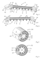
- the plastic strand of the Fig.1 is designated by the reference numeral 1 and has a first, inner elastomer layer 2, a second, overlying elastomer layer 3 and a third, outer elastomer layer 4.
- the plastic strand 1 has a first, elastomeric connecting section 6 and at a second end a second connecting section 7.
- the inner elastomer layer 2 has a plurality of jagged ribs 9.
- the outer elastomer layer 4 also has a series of ribs 10 on an outer side.
- the first connecting section 6 has a receiving opening 12, which has an undercut edge 13 and a neck region 14.
- the second connecting section 7 has a plug-in region in the form of a barb 16, which is shaped complementarily to the receiving opening 12 and also has a neck region 17. Furthermore, the barb 16 has a triangular region 18.
- An elastomer coating 20 made of thermoplastic vulcanizate is arranged in the neck region 14 of the receiving opening 12 and forms an inner surface of the neck region 14. Furthermore, the barb 16 has an elastomer coating 21 made of thermoplastic vulcanizate in its triangular region 18, which forms an outer surface of the triangular region 18.
- the two connecting sections 6 and 7 are made of the same elastomer material as the second and middle elastomer layers 3, respectively.
- the inner elastomer layer 2 is made of the same elastomer material as the outer elastomer layer 4.
- the ribs 9 are made of the same material as the rest of the inner elastomer layer 2.
- the elastomer of the inner elastomer layer 2 and the outer elastomer layer 4 is foam rubber, while the elastomer of the middle elastomer layer 3 is soft rubber, which has a hardness of 80 to 90 Shore-A, whereby a hardness of the soft rubber of 60 to 90 Shore-A would also be possible.
- the foam rubber can, for example, have a hardness of 15 to 40 Shore-A.
- the ring of the Fig.3 is designated by the reference number 24.
- the ring 24 has a cavity 25 in which cables or one or more lines (not shown) can be arranged. Due to the softness of the foam rubber of the inner elastomer layer 2 and its design with ribs 9, a flexible adaptation of the cavity 25 to the cables or lines is possible by appropriate deformation of the ribs 9, so that vibrations and associated noises are largely prevented. The same applies to the outer elastomer layer 4 if it comes into contact with another component.
- the barb 16 with its elastomer coating 21 must be guided along the elastomer coating 20, which occurs against a relatively high resistance due to the increased hardness of the thermoplastic vulcanizate of the two coatings 20, 21 compared to the soft rubber.
- a sound which can serve as acoustic feedback for the locking of the barb 16 in the receiving opening 12.
- the plastic strand 1' of the Fig.5 differs from the plastic strand 1 of the Fig.1 in that it additionally has a fastening element 30.
- This consists of a base 31, which is an integral part of a first connecting section 6', and a pin 32.
- the base 31 has a cavity 34 in which a head 35 of the pin 32 is held. While the base 31 is made of the same elastomer material as the rest of the first connecting section 6' (apart from the elastomer coating 20), the pin 32 is made of a thermoplastic material.
- the pin 32 is pressed into a corresponding opening, which can be provided, for example, by a bushing (not shown).
- a fastening option can be desired in particular in a shell, in a housing or in vehicle construction.
- plastic strand 1' The other features of the plastic strand 1' are the same as those of the plastic strand 1 of the Fig. 1 and 2 .
Landscapes
- Engineering & Computer Science (AREA)
- General Engineering & Computer Science (AREA)
- Mechanical Engineering (AREA)
- Architecture (AREA)
- Civil Engineering (AREA)
- Structural Engineering (AREA)
- Flexible Shafts (AREA)
Description
- Die Erfindung bezieht sich auf einen Kunststoffstrang mit einem ersten und zweiten Ende, die so miteinander verbunden werden können, dass ein Ring gebildet ist. Der Ring ist zum Umschließen von einem oder mehreren Kabeln bzw. einer oder mehreren Leitungen vorgesehen. Der Ring dient dazu, Geräusche zu vermeiden, die dadurch entstehen können, dass Kabel oder Leitungen vibrieren und bei Kontakt mit einem benachbarten Bauteil Geräusche erzeugen. Ferner kann der Ring auch dazu dienen, mehrere Kabel oder Leitungen zu bündeln.
- Aus der
US-A-3 161 210 ist ein Schlauch aus Gummi bekannt, der über eine Rohr- oder Schlauchleitung gezogen werden kann und eine Vielzahl von sich in Längsrichtung erstreckenden Rippen aufweist. Der Schlauch dient dazu, die Leitung gegen Beschädigungen zu schützen und gegen Schwingungen zu isolieren. Der Schlauch wird aus einem Strang gebildet, der mittels der Rippen zu dem Schlauch verschlossen wird. - Auch aus der
EP 1 099 899 A2 ist ein Schlauch zur Halterung von Rohrleitungen bekannt. Dieser Schlauch besteht aus einem Verbundwerkstoff aus zumindest zwei Elastomeren, und er wird aus einem Strang dadurch gebildet, dass ein Widerhaken an einem Ende des Strangs in eine hinterschnittene Ausnehmung an einem anderen Ende des Strangs gedrückt wird. Das Elastomer der Bereiche der Ausnehmung und des Widerhakens ist härter als das übrige Elastomer des Schlauches. Im Inneren weist der Schlauch eine Vielzahl von Rippen auf. - Eine Weiterbildung eines solchen Schlauches bzw. elastomeren Leitungsdämpfers ist in der
EP 2 878 874 B1 beschrieben. Während der Leitungsdämpfer gemäß derEP 1 099 899 B1 aus elatomerem Vollmaterial hergestellt ist, weist der Leitungsdämpfer gemäß derEP 2 878 874 B1 einen Umfangsabschnitt aus einem ersten porösen Elastomermaterial auf und die Rippen bzw. Zacken sind aus einem zweiten porösen Elastomermaterial gebildet. Dabei ist die Porengröße des Elastomermaterials in den Zacken größer als die Porengröße in dem Umfangsabschnitt. Der Leitungsdämpfer weist einen aus einheitlichem Vollmaterial hergestellten Verschlussabschnitt auf, der eine Aufnahmeöffnung und einen korrespondierenden Widerhaken besitzt. Dadurch wird eine erhöhte Festigkeit des Verschlussabschnittes erreicht. - Ein elastomerer Leitungsdämpfer zum Umschließen einer Rohrleitung ist auch aus der
US 2002/0070316 A1 bekannt. Dieser Leitungsdämpfer weist eine äußere, thermoplastische Schicht und eine innere, geschäumte Schicht auf. Der Leitungsdämpfer wird aus einem Strang in die Form einer Rohrklemme geführt, indem eine durch die thermoplastische Schicht begrenzte Vorwölbung in eine ebenfalls durch diese Schicht begrenzte Ausnehmung gedrückt wird. - Aus der
EP 1 106 900 A1 ist eine vibrationsisolierende Rohrschellenanordnung bekannt, die drei Schichten aufweist. Dabei ist die mittlere Schicht aus einem elastischen Material, während die beiden äußeren Schichten aus einem festeren Material sind. - Die
DE 10 2016 116 231 A1 und dieDE 10 2016 238A1 offenbaren jeweils einen elastischen Abstandshalter zum Dämpfen von Vibrationen und zur Abstandshaltung einer Leitung, insbesondere eines Fahrzeugs, wobei der Abstandshalter an einem Fahrzeugbauteil mittels eines Befestigungsstifts bzw. eines Befestigungsfußes mit elastischen Haltelippen befestigt werden kann. - Weiterhin ist aus der
US 5 013 166 A eine Halterung für einen Torsionsstab bekannt, die unterschiedlich elastische Schichten aufweist. - Der Erfindung liegt die Aufgabe zugrunde, einen Kunststoffstrang der eingangs genannten Art zur Verfügung zu stellen, der als geschlossener Ring sowohl auf einer Innenseite als auch auf einer Außenseite gute Geräuschminderungseigenschaften hat und ferner eine hohe Festigkeit sowie eine gute Stabilität der Verbindung der beiden Strangenden aufweist.
- Diese Aufgabe wird durch die Merkmale des Anspruchs 1 gelöst. Zusätzlich zu den oben genannten Merkmalen weist der Kunststoffstrang über seine Dicke bzw. im Querschnitt eine erste, innere Elastomerschicht und darüberliegend eine zweite Elastomerschicht auf. Das Elastomer der ersten Schicht ist weicher als das Elastomer der zweiten Schicht. Die innere Elastomerschicht besitzt auf einer Innenseite, die bei der Bildung eines Ringes nach innen weist, Rippen oder Noppen auf. Ferner besitzt der Strang über seine Dicke eine dritte, äußere Elastomerschicht deren Elastomer ebenfalls weicher ist als das Elastomer der zweiten Schicht.
- Der Strang hat an dem ersten Ende einen ersten, elastomeren Verbindungsabschnitt und an dem zweiten Ende einen zweiten, elastomeren Verbindungsabschnitt. Der erste Verbindungsabschnitt besitzt eine Aufnahmeöffnung, und der zweite Verbindungsabschnitt einen Steckbereich, der in die Aufnahmeöffnung eingeführt werden kann. Durch einen solchen Eingriff des Steckbereichs mit der Aufnahmeöffnung wird der Strang zu einem Ring geformt. Eine Innenfläche der Aufnahmeöffnung weist zumindest teilweise eine Elastomerbeschichtung auf, die härter ist als der restliche Teil des ersten Verbindungsabschnitts. Eine Außenfläche des Steckbereichs weist ebenfalls zumindest teilweise eine Elastomerbeschichtung auf, die härter ist als der restliche Teil des zweiten Verbindungsabschnitts.
- Dadurch, dass der Kunststoffstrang und somit der aus diesem gebildete Ring zumindest drei Elastomerschichten aufweist, wobei eine innere und eine äußere Schicht aus einem weicheren Elastomer hergestellt sind als eine dazwischen liegende Elastomerschicht, ist zum einen erreicht, dass eine effektive Vermeidung von Geräuschen stattfindet, wenn der Ring ein oder mehrere Kabel oder zumindest eine Leitung umgibt und dabei vibriert, wie dies insbesondere bei Verwendung in einem Kraftfahrzeug der Fall sein kann. Zum anderen ist aber auch eine hohe Festigkeit des Ringes aufgrund des härteren Elastomers der zweiten Elastomerschicht gewährleistet. Dadurch, dass zumindest ein Teil der Innenfläche der Aufnahmeöffnung und zumindest ein Teil der Außenfläche des Steckbereichs mit einer Elastomerbeschichtung versehen sind, die härter ist, als der jeweils restliche Teil des Verbindungsabschnitts, weist der Verschluss des Ringes, der dadurch gegeben ist, dass der Steckbereich und die Ausnahmeöffnung miteinander in Eingriff sind, eine hohe Stabilität bzw. Sicherheit auf. Dies ergibt sich aus dem relativ hohen Härtegrad der beiden Elastomerbeschichtungen und daraus, dass somit beim Verbinden der beiden Verbindungsabschnitte ein gewisser Widerstand überwunden werden muss, so dass von einem Verrasten gesprochen werden kann. Der Verschluss kann auch als Clip-Verschluss bezeichnet werden, und die beiden Verbindungsabschnitte als Clip-Abschnitte.
- Die Weichheit der ersten und der dritten Elastomerschicht wirken sich insbesondere günstig bei elektrisch angetriebenen Kraftfahrzeugen aus, da diese aufgrund ihres Antriebs im Vergleich zu einem Fahrzeug mit einem Verbrennungsmotor einen relativ geringen Geräuschpegel erzeugen.
- Vorzugsweise sind die Aufnahmeöffnung und der Steckbereich, insbesondere die beiden Elastomerbeschichtungen, so geartet, dass beim Einführen des Steckbereichs in die Aufnahmeöffnung ein hörbares Geräusch entsteht. Dieses stellt vorteilhafterweise eine akustische Rückmeldung dahingehend dar, dass beim Zusammenfügen der beiden Enden des Kunststoffstrangs ein Verrasten des Steckbereichs mit der Aufnahmeöffnung stattgefunden hat.
- Die erfindungsgemäßen relativen Unterschiede in der Weichheit bzw. Härte können insbesondere nach Shore-A gemessen werden bzw. gegeben sein.
- Vorzugsweise ist die Elastomerbeschichtung der Aufnahmeöffnung aus thermoplastischem Vulkanisat (TPV) hergestellt. Gleiches gilt für die Elastomerbeschichtung des Steckbereichs. Die mindere Deformationsrate von thermoplastischem Vulkanisat sorgt dafür, dass beim Zusammenführen von Steckbereich und Aufnahmeöffnung ein erhöhter Widerstand zu überwinden ist. Dies sorgt für eine sichere Verbindung und die Erzeugung eines akustischen Signals am Ende des Verschließvorgangs. Möglich sind als Material für die Elastomerbeschichtungen aber auch andere thermoplastische Elastomere.
- Die Dicke der Elastomerbeschichtungen kann insbesondere zwischen 0,15 bis 0,25 mm liegen, vorzugsweise beträgt sie ca. 0,2 mm. Eine solche Dicke sorgt für ein günstiges Maß an Flexibilität der Beschichtungen.
- Vorzugsweise sind die innere und die äußere Elastomerschicht aus Porengummi hergestellt. Durch die poröse bzw. zellige Struktur dieses Gummis ist eine Weichheit gegeben, die eine Vibrationsdämpfung fördern und Klappergeräusche effektiv verhindern kann. Bei dem Porengummi kann es sich insbesondere um Moosgummi handeln. Vorteilhaft ist auch die Verwendung von Schaumgummi. Vorzugsweise sind die innere und die äußere Elastomerschicht aus demselben Material hergestellt.
- Die zweite Elastomerschicht, die zwischen der ersten bzw. inneren und der dritten bzw. äußeren Elastomerschicht liegt, ist vorzugsweise aus Weichgummi hergestellt. Das Weichgummi besitzt vorzugsweise eine Härte von 60 bis 90 Shore-A. Die Härte kann insbesondere 80 bis 90 Shore-A betragen. Auf diese Weise wird eine hohe Festigkeit des Kunststoffstrangs und des daraus gebildeten Ringes erreicht.
- Es ist auch vorteilhaft, wenn die beiden Verbindungsabschnitte - abgesehen von den beiden Elastomerbeschichtungen - aus demselben Material hergestellt sind wie die zweite Elastomerschicht. Dies vereinfacht die Herstellung des Kunststoffstrangs und bewirkt auch eine gute Festigkeit der beiden Verbindungsabschnitte.
- Es ist vorteilhaft, wenn die Aufnahmeöffnung einen hinterschnittenen Rand aufweist und es sich bei dem Steckbereich um einen dazu komplementären Widerhaken handelt. Dabei besitzen die Aufnahmeöffnung und der Steckbereich jeweils einen Halsbereich und einen Dreiecksbereich, wobei die Halsbereiche und die Dreiecksbereiche jeweils zueinander komplementär sind. Auf diese Weise wird eine sichere Verbindung der beiden Enden des Kunststoffstrangs ermöglicht. Eine solche Verbindung ist gegenüber einer Zugbeanspruchung besonders widerstandsfähig. Bei einer solchen Ausgestaltung der Verbindungsabschnitte befindet sich die Elastomerbeschichtung des ersten Verbindungsabschnitts vorzugsweise in dem Halsbereich der Aufnahmeöffnung und die Elastomerbeschichtung des zweiten Verbindungsabschnitts in dem Dreiecksbereich des Widerhakens. Dies bedeutet, dass beim Verknüpfen der beiden Verbindungsabschnitte, die Elastomerschicht des Widerhakens entlang der Elastomerschicht der Aufnahmeöffnung geführt wird, wodurch ein erhöhter Widerstand überwunden werden muss, bis der Dreiecksbereich des Widerhakens sich vollständig in dem Dreiecksbereich der Aufnahmeöffnung befindet, also eine Verrastung stattfindet. Zum Zeitpunkt der Verrastung kann wie oben beschrieben ein Geräusch entstehen, das als akustische Rückmeldung für ein erfolgreiches Verrasten genutzt werden kann.
- Insbesondere kann der Kunststoffstrang genau drei Elastomerschichten aufweisen, so dass es sich bei der zweiten Elastomerschicht um eine mittlere Schicht handelt, die mit einer Innenseite an die erste Elastomerschicht und mit einer Außenseite an die dritte Elastomerschicht angrenzt. Auch die äußere Elastomerschicht weist vorzugsweise auf einer Außenseite Rippen oder Noppen auf. Auf diese Weise wird die Fähigkeit einer Verformung des äußeren Umfangs eines Ringes bei Druckausübung erhöht, was zu besonders guten Dämpfungseigenschaften beiträgt.
- Der Kunststoffstrang kann ein Befestigungselement aufweisen, das dazu vorgesehen ist, einen aus ihm gebildeten Ring an einem Gegenstand zu befestigen. Dies kann insbesondere nützlich sein, wenn Kabel oder Leitungen mittels des Ringes befestigt werden sollen.
- Der Kunststoffstrang kann auch farbig ausgestaltet sein, insbesondere auch einen Farbstreifen aufweisen, wodurch auf eine bestimmte vorgesehene Verwendung hinwiesen werden kann.
- Der aus dem Kunststoffstrang gebildete Ring kann in Längsrichtung auch eine relativ große Ausdehnung aufweisen, von beispielsweise bis zu 50 cm, so dass man dann auch von einem Schlauch sprechen könnte.
- Vorzugsweise besitzen die erste und die dritte Elastomerschicht eine Härte von 15 bis 40 Shore-A, wobei die beiden Elastomerschichten unterschiedlich hart sein können.
- Im Folgenden wird die Erfindung anhand zweier Ausführungsbeispiele näher erläutert, wobei auf die Figuren Bezug genommen wird. Es zeigen:
-
Fig. 1 eine perspektivische, seitliche Ansicht auf einen erfindungsgemäßen Kunststoffstrang, -
Fig. 2 eine seitliche Draufsicht auf den Kunststoffstrang derFig. 1 , -
Fig. 3 eine perspektivische Ansicht eines aus dem Kunststoffstrang derFig. 1 gebildeten Ringes, -
Fig. 4 eine seitliche Draufsicht auf den Ring derFig. 3 , -
Fig. 5 eine perspektivische seitliche Ansicht auf einen anderen, erfindungsgemäßen Kunststoffstrang, der ein Element zur Befestigung an einem Gegenstand aufweist, -
Fig. 6 eine seitliche Draufsicht auf den Kunststoffstrang derFig. 5 , -
Fig. 7 eine perspektivische Ansicht eines aus dem Kunststoffstrang derFig. 5 gebildeten Ringes, -
Fig. 8 eine seitliche Draufsicht auf den Ring derFig. 7 . - Der Kunststoffstrang der
Fig. 1 ist mit dem Bezugszeichen 1 bezeichnet und weist eine erste, innere Elastomerschicht 2, eine zweite, darüberliegende Elastomerschicht 3 und eine dritte, äußere Elastomerschicht 4 auf. - An einem ersten Ende hat der Kunststoffstrang 1 einen ersten, elastomeren Verbindungsabschnitt 6 und an einem zweiten Ende einen zweiten Verbindungsabschnitt 7.
- Die innere Elastomerschicht 2 weist eine Vielzahl von zackenartigen Rippen 9 auf. Die äußere Elastomerschicht 4 besitzt auf einer Außenseite ebenfalls eine Reihe von Rippen 10.
- Der erste Verbindungsabschnitt 6 besitzt eine Aufnahmeöffnung 12, die einen hinterschnittenen Rand 13 und einen Halsbereich 14 aufweist. Der zweite Verbindungsabschnitt 7 besitzt einen Steckbereich in Form eines Widerhakens 16, der komplementär zu der Aufnahmeöffnung 12 geformt ist und ebenfalls einen Halsbereich 17 aufweist. Ferner besitzt der Widerhaken 16 einen Dreiecksbereich 18.
- In dem Halsbereich 14 der Aufnahmeöffnung 12 ist eine Elastomerbeschichtung 20 aus thermoplastischem Vulkanisat angeordnet, die eine Innenfläche des Halsbereiches 14 bildet. Ferner weist der Widerhaken 16 in seinem Dreiecksbereich 18 eine Elastomerbeschichtung 21 aus thermoplastischem Vulkanisat auf, die eine Außenfläche des Dreiecksbereichs 18 bildet.
- Von den Elastomerbeschichtungen 20 und 21 abgesehen, sind die beiden Verbindungsabschnitte 6 und 7 aus demselben Elastomermaterial hergestellt wie die zweite bzw. mittlere Elastomerschicht 3. Ferner ist die innere Elastomerschicht 2 aus demselben Elastomermaterial hergestellt wie die äußere Elastomerschicht 4. Der Klarheit halber sei auch darauf hingewiesen, dass die Rippen 9 aus demselben Material bestehen wie die restliche innere Elastomerschicht 2. Bei dem Elastomer der inneren Elastomerschicht 2 und der äußeren Elastomerschicht 4 handelt es sich um Moosgummi, während es sich bei dem Elastomer der mittleren Elastomerschicht 3 um Weichgummi, das eine Härte von 80 bis 90 Shore-A aufweist, handelt, wobei insbesondere auch eine Härte des Weichgummis von 60 bis 90 Shore-A möglich wäre. Das Moosgummi kann z. B. eine Härte von 15 bis 40 Shore-A aufweisen.
- Der durch Verbinden der beiden Verbindungsabschnitte 6 und 7 entstandene Ring der
Fig. 3 ist mit dem Bezugszeichen 24 bezeichnet. Der Ring 24 besitzt einen Hohlraum 25, in dem Kabel oder eine bzw. mehrere Leitungen (nicht gezeigt) angeordnet sein können. Aufgrund der Weichheit des Moosgummis der inneren Elastomerschicht 2 und deren Ausgestaltung mit Rippen 9 ist eine flexible Anpassung des Hohlraums 25 an die Kabel bzw. Leitungen durch eine entsprechende Deformation der Rippen 9 möglich, so dass Vibrationen und damit verbundene Geräusche weitestgehend verhindert sind. Entsprechendes gilt auch für die äußere Elastomerschicht 4, wenn diese in Kontakt mit einem anderen Bauteil gelangt. - Zum Verbinden der beiden Enden des Kunststoffstrangs 1 muss der Widerhaken 16 mit seiner Elastomerbeschichtung 21 entlang der Elastomerbeschichtung 20 geführt werden, was aufgrund der gegenüber dem Weichgummi erhöhten Härte des thermoplastischen Vulkanisats der beiden Beschichtungen 20, 21 gegen einen relativ hohen Widerstand geschieht. Infolge dieses erhöhten Widerstandes entsteht dann, wenn der Dreiecksbereich 18 vollständig in einen komplementären Dreiecksbereich 26 der Aufnahmeöffnung 12 gelangt ist, ein Geräusch, das als akustische Rückmeldung für das Verrasten der Widerhakens 16 in der Aufnahmeöffnung 12 dienen kann.
- In den Figuren sind gleiche Merkmale mit gleichen Bezugszeichen bezeichnet. Der Kunststoffstrang 1' der
Fig. 5 unterscheidet sich von dem Kunststoffstrang 1 derFig. 1 dadurch, dass er zusätzlich ein Befestigungselement 30 aufweist. Dieses besteht aus einem Sockel 31, der integraler Bestandteil eines ersten Verbindungsabschnitts 6' ist, und einem Stift 32. Der Sockel 31 weist einen Hohlraum 34 auf, in dem ein Kopf 35 des Stiftes 32 gehalten ist. Während der Sockel 31 aus demselben Elastomermaterial hergestellt ist wie der restliche Teil des ersten Verbindungsabschnitts 6` (abgesehen von der Elastomerbeschichtung 20), ist der Stift 32 aus einem thermoplastischen Material hergestellt. Zur Befestigung des aus dem Kunststoffstrang 1' durch Verknüpfen der beiden Verbindungsabschnitte 6' und 7 hergestellten Ringes 24' (sieheFig. 7 und 8 ) an einem Bauteil wird der Stift 32 in eine korrespondierende Öffnung, die beispielsweise durch eine Buchse (nicht gezeigt) gegeben sein kann, gedrückt. Eine solche Befestigungsmöglichkeit kann insbesondere bei einem Rohbau, in einem Gehäuse oder im Fahrzeugbau gewünscht sein. - Die weiteren Merkmale des Kunststoffstrangs 1' sind dieselben wie bei dem Kunststoffstrang 1 der
Fig. 1 und 2 . -
- 1, 1'
- Kunststoffstrang
- 2
- erste Elastomerschicht
- 3
- zweite Elastomerschicht
- 4
- dritte Elastomerschicht
- 6, 6'
- erster Verbindungsabschnitt
- 7
- zweiter Verbindungsabschnitt
- 9
- Rippen
- 10
- Rippen
- 12
- Aufnahmeöffnung
- 13
- hinterschnittener Rand von 12
- 14
- Halsbereich von 12
- 16
- Widerhaken
- 17
- Halsbereich von 16
- 18
- Dreiecksbereich von 16
- 20
- Elastomerbeschichtung von 12
- 21
- Elastomerbeschichtung von 16
- 24, 24'
- Ring
- 25
- Hohlraum
- 26
- Dreiecksbereich von 12
- 30
- Befestigungselement
- 31
- Sockel
- 32
- Stift
- 34
- Hohlraum
- 35
- Kopf von 32
Claims (15)
- Kunststoffstrang (1) mit einem ersten und einem zweiten Ende, wobei die beiden Enden so miteinander verbindbar sind, dass ein zum Umschließen von Kabeln oder Leitungen dienender Ring (24) gebildet ist,wobei der Strang (1) über seine Dicke eine erste, innere Elastomerschicht (2) und eine zweite, darüberliegende Elastomerschicht (3) aufweist, wobei das Elastomer der ersten Elastomerschicht (2) weicher ist als das Elastomer der zweiten Elastomerschicht (3),wobei die erste Elastomerschicht (2) auf einer Innenseite Rippen (9) oder Noppen aufweist,wobei der Strang (1) über seine Dicke eine dritte, äußere Elastomerschicht (4) aufweist, deren Elastomer weicher ist als das Elastomer der zweiten Elastomerschicht (3),wobei der Strang (1) zum Verbinden der Enden an dem ersten Ende einen ersten, elastomeren Verbindungsabschnitt (6), der eine Aufnahmeöffnung (12) besitzt, und an dem zweiten Ende einen zweiten, elastomeren Verbindungsabschnitt (7), der einen in die Aufnahmeöffnung (12) einführbaren Steckbereich (16) besitzt, aufweistund wobei eine Innenfläche der Aufnahmeöffnung (12) zumindest teilweise durch eine verglichen mit dem restlichen ersten Verbindungsabschnitt (6) härtere Elastomerbeschichtung (20) gegeben ist und eine Außenfläche des Steckbereichs (16) zumindest teilweise durch eine verglichen mit dem restlichen zweiten Verbindungsabschnitt (7) härtere Elastomerbeschichtung (21) gegeben ist.
- Strang (1) nach Anspruch 1,
dadurch gekennzeichnet, dass die Aufnahmeöffnung (12) und der Steckbereich (16) so beschaffen sind, dass beim Einführen des Steckbereichs (16) des zweiten Verbindungsabschnitts (7) in die Aufnahmeöffnung (12) des ersten Verbindungsabschnitts (6) ein hörbares Geräusch entsteht. - Strang (1) nach Anspruch 1 oder 2,
dadurch gekennzeichnet, dass die Elastomerbeschichtung (20) der Aufnahmeöffnung (12) und/oder die Elastomerbeschichtung (21) des Steckbereichs (16) aus thermoplastischem Vulkanisat besteht (TPV). - Strang (1) nach einem der vorhergehenden Ansprüche,
dadurch gekennzeichnet, dass die Elastomerbeschichtungen (20, 21) des ersten und des zweiten Verbindungsabschnitts (6, 7) eine Dicke von 0,15 bis 0,25 mm, vorzugsweise von 0,2 mm, aufweisen. - Strang (1) nach einem der vorhergehenden Ansprüche,
dadurch gekennzeichnet, dass die erste Elastomerschicht (2) und die dritte Elastomerschicht (4) aus Porengummi, vorzugsweise aus Moosgummi oder Schaumgummi, hergestellt sind. - Strang (1) nach einem der vorhergehenden Ansprüche,
dadurch gekennzeichnet, dass die erste Elastomerschicht (2) und die dritte Elastomerschicht (4) aus demselben Material hergestellt sind. - Strang (1) nach einem der vorhergehenden Ansprüche,
dadurch gekennzeichnet, dass die zweite Elastomerschicht (3) aus Weichgummi, vorzugsweise mit einer Härte von 60-90 Shore-A, hergestellt ist. - Strang (1) nach einem der vorhergehenden Ansprüche,
dadurch gekennzeichnet, dass die zweite Elastomerschicht (3) und die beiden Verbindungsabschnitte (6, 7), abgesehen von den beiden Elastomerbeschichtungen (20, 21), aus demselben Material hergestellt sind. - Strang (1) nach einem der vorhergehenden Ansprüche,
dadurch gekennzeichnet, dass die Aufnahmeöffnung (12) einen hinterschnittenen Rand (13) aufweist und der Steckbereich ein dazu komplementärer Widerhaken (16) ist, wobei die Aufnahmeöffnung (12) und der Widerhaken (16) jeweils zueinander komplementäre Halsbereiche (14, 17) und Dreiecksbereiche (26, 18) haben. - Strang (1) nach Anspruch 9,
dadurch gekennzeichnet, dass die Elastomerbeschichtung (20) des ersten Verbindungsabschnitts (6) in dem Halsbereich (14) der Aufnahmeöffnung (12) und die Elastomerbeschichtung (21) des zweiten Verbindungsabschnitts (7) in dem Dreiecksbereich (18) des Widerhakens (16) gegeben ist. - Strang (1) nach einem der vorhergehenden Ansprüche,
dadurch gekennzeichnet, dass er (1), abgesehen von den beiden Verbindungsabschnitten (6, 7), über seine Dicke genau drei Elastomerschichten (2, 3, 4) aufweist, so dass die zweite Elastomerschicht (3) eine mittlere Schicht ist, die mit einer Innenseite an die erste Elastomerschicht (2) und mit einer Außenseite an die dritte Elastomerschicht (4) angrenzt. - Strang (1) nach einem der vorhergehenden Ansprüche,
dadurch gekennzeichnet, dass die dritte Elastomerschicht (4) auf einer Außenseite Rippen (10) oder Noppen aufweist. - Strang (1') nach einem der vorhergehenden Ansprüche,
dadurch gekennzeichnet, dass er (1') ein Befestigungselement (30) aufweist, das, wenn er (1') zu einem Ring (24') geschlossen ist, zu dessen Befestigung an einem Gegenstand dient. - Strang (1, 1') nach einem der vorhergehenden Ansprüche,
dadurch gekennzeichnet, dass das erste und das zweite Ende miteinander verbunden sind und der Strang (1, 1') somit einen Ring (24, 24') bildet. - Strang (1, 1') nach einem der vorhergehenden Ansprüche,
dadurch gekennzeichnet, dass die erste Elastomerschicht (2) und die dritte Elastomerschicht (4) eine Härte von 15-40 Shore-A aufweisen.
Applications Claiming Priority (1)
| Application Number | Priority Date | Filing Date | Title |
|---|---|---|---|
| DE102021133241.9A DE102021133241A1 (de) | 2021-12-15 | 2021-12-15 | Zu einem Ring verschließbarer Kunststoffstrang für Kabel oder Leitungen |
Publications (2)
| Publication Number | Publication Date |
|---|---|
| EP4198372A1 EP4198372A1 (de) | 2023-06-21 |
| EP4198372B1 true EP4198372B1 (de) | 2024-08-21 |
Family
ID=84488131
Family Applications (1)
| Application Number | Title | Priority Date | Filing Date |
|---|---|---|---|
| EP22212753.2A Active EP4198372B1 (de) | 2021-12-15 | 2022-12-12 | Zu einem ring verschliessbarer kunststoffstrang für kabel oder leitungen |
Country Status (2)
| Country | Link |
|---|---|
| EP (1) | EP4198372B1 (de) |
| DE (1) | DE102021133241A1 (de) |
Families Citing this family (1)
| Publication number | Priority date | Publication date | Assignee | Title |
|---|---|---|---|---|
| EP4647640A1 (de) * | 2024-05-06 | 2025-11-12 | Poppe Elastomertechnik GmbH | Elastisches dämpfungs- und befestigungselement |
Family Cites Families (10)
| Publication number | Priority date | Publication date | Assignee | Title |
|---|---|---|---|---|
| US3161210A (en) | 1961-06-19 | 1964-12-15 | Loof Nils Oskar Tore | Plastic strips |
| FR2642487B1 (fr) | 1989-01-31 | 1991-05-10 | Hutchinson | Palier de barre de torsion |
| DE29919710U1 (de) | 1999-11-11 | 2000-03-02 | Poppe + Co. Gießener Gummiwarenfabrik GmbH & Co. KG, 35392 Gießen | Schlauch |
| NL1013700C2 (nl) | 1999-11-30 | 2001-06-01 | Walraven J Van Bv | Trillingisolerend pijpbeugelsamenstel. |
| US6601802B1 (en) * | 1999-12-30 | 2003-08-05 | Lsp Products Group Inc | Method for making extruded acoustic pipe support |
| FR2888166B1 (fr) * | 2005-07-08 | 2007-10-12 | Allevard Rejna Autosuspensions | Bague d'arret destinee a etre montee sur une barre stabilisatrice d'une suspension de vehicule automobile |
| DE102013113224A1 (de) | 2013-11-29 | 2015-06-03 | Poppe GmbH | Elastomerer Leitungsdämpfer |
| DE102016116247A1 (de) * | 2016-08-31 | 2018-03-01 | Poppe GmbH | Elastischer vibrationsdämpfer |
| DE102016116238A1 (de) | 2016-08-31 | 2018-03-01 | Poppe GmbH | Elastischer abstandshalter |
| DE102016116231A1 (de) | 2016-08-31 | 2018-03-01 | Poppe GmbH | Elastischer Abstandshalter |
-
2021
- 2021-12-15 DE DE102021133241.9A patent/DE102021133241A1/de not_active Withdrawn
-
2022
- 2022-12-12 EP EP22212753.2A patent/EP4198372B1/de active Active
Also Published As
| Publication number | Publication date |
|---|---|
| DE102021133241A1 (de) | 2023-06-15 |
| EP4198372A1 (de) | 2023-06-21 |
Similar Documents
| Publication | Publication Date | Title |
|---|---|---|
| DE602004002123T3 (de) | Halteelement | |
| EP1729388B1 (de) | Befestigungsvorrichtung für mehrere Leitungen | |
| DE602004002139T2 (de) | Schwingungsisolierende Klammer für langgestreckte Gegenstände | |
| DE112010005160B4 (de) | Durchgangstülle mit Schalldämpfer | |
| DE69910175T2 (de) | Schalldämmatte mit angeformtem befestigungselement | |
| DE102018217222B4 (de) | Durchführungshülse | |
| DE102016005012A1 (de) | Interdentalreiniger | |
| DE10244813A1 (de) | Tülle | |
| DE3737987A1 (de) | Aufhaengeoese fuer eine abgasanlage eines kraftfahrzeugs | |
| EP1515862A1 (de) | Pendelstütze aus einem strangpressprofil | |
| EP1487632B1 (de) | Verformbares bauteil, insbesondere ausstattungsteil für ein kraftfahrzeug, und verfahren zu seiner herstellung | |
| DE29618513U1 (de) | Halter für rohrförmige Bauteile | |
| DE112018001913T5 (de) | Verbindungsvorrichtung, Clippatrize, Sitzbezug und Sitz | |
| EP3152469A1 (de) | Vorrichtung zum einstellen einer bewegung eines bedienelements für ein automatikgetriebe eines fahrzeugs, verfahren zum herstellen derselben und schaltvorrichtung zum schalten eines automatikgetriebes eines fahrzeugs | |
| EP1749061B1 (de) | Schallisolierendes bauteil aus hochgefülltem thermoplastischen elastomer auf basis von styrol | |
| DE102007061641A1 (de) | Ablenkeinrichtung | |
| DE3024091C2 (de) | Hydraulisch dämpfendes Einkammerlager | |
| EP4198372A1 (de) | Zu einem ring verschliessbarer kunststoffstrang für kabel oder leitungen | |
| DE102024106473A1 (de) | Schalldämmabdeckung | |
| DE102008021206B4 (de) | Schwingungsdämpfendes elastisches Lager mit einem Formkörper aus Elastomerwerkstoff | |
| DE202005007646U1 (de) | Schallisolierende Verkleidung, insbesondere innenseitige Stirnwandverkleidung für Kraftfahrzeuge | |
| DE69931581T2 (de) | Kabeldurchführungsanordnung | |
| EP1591292A1 (de) | Verstärkungsträger, Dichtung mit einem solchen Verstärkungsträger und Verfahren zum Herstellen einer solchen Dichtung | |
| DE60302267T2 (de) | Verfahren zur Herstellung eines mit einem Halter verbundenen Gelenks | |
| WO2008135258A2 (de) | Zahnbürste mit bürstenkopf und trägerkörper aus verschiedenen kunststoffen |
Legal Events
| Date | Code | Title | Description |
|---|---|---|---|
| PUAI | Public reference made under article 153(3) epc to a published international application that has entered the european phase |
Free format text: ORIGINAL CODE: 0009012 |
|
| STAA | Information on the status of an ep patent application or granted ep patent |
Free format text: STATUS: THE APPLICATION HAS BEEN PUBLISHED |
|
| AK | Designated contracting states |
Kind code of ref document: A1 Designated state(s): AL AT BE BG CH CY CZ DE DK EE ES FI FR GB GR HR HU IE IS IT LI LT LU LV MC ME MK MT NL NO PL PT RO RS SE SI SK SM TR |
|
| STAA | Information on the status of an ep patent application or granted ep patent |
Free format text: STATUS: REQUEST FOR EXAMINATION WAS MADE |
|
| 17P | Request for examination filed |
Effective date: 20231121 |
|
| RBV | Designated contracting states (corrected) |
Designated state(s): AL AT BE BG CH CY CZ DE DK EE ES FI FR GB GR HR HU IE IS IT LI LT LU LV MC ME MK MT NL NO PL PT RO RS SE SI SK SM TR |
|
| GRAP | Despatch of communication of intention to grant a patent |
Free format text: ORIGINAL CODE: EPIDOSNIGR1 |
|
| STAA | Information on the status of an ep patent application or granted ep patent |
Free format text: STATUS: GRANT OF PATENT IS INTENDED |
|
| RIC1 | Information provided on ipc code assigned before grant |
Ipc: H02G 3/32 20060101ALI20240301BHEP Ipc: F16L 57/06 20060101ALI20240301BHEP Ipc: F16L 55/035 20060101ALI20240301BHEP Ipc: F16L 55/033 20060101AFI20240301BHEP |
|
| INTG | Intention to grant announced |
Effective date: 20240320 |
|
| GRAS | Grant fee paid |
Free format text: ORIGINAL CODE: EPIDOSNIGR3 |
|
| GRAA | (expected) grant |
Free format text: ORIGINAL CODE: 0009210 |
|
| STAA | Information on the status of an ep patent application or granted ep patent |
Free format text: STATUS: THE PATENT HAS BEEN GRANTED |
|
| AK | Designated contracting states |
Kind code of ref document: B1 Designated state(s): AL AT BE BG CH CY CZ DE DK EE ES FI FR GB GR HR HU IE IS IT LI LT LU LV MC ME MK MT NL NO PL PT RO RS SE SI SK SM TR |
|
| REG | Reference to a national code |
Ref country code: GB Ref legal event code: FG4D Free format text: NOT ENGLISH |
|
| REG | Reference to a national code |
Ref country code: CH Ref legal event code: EP |
|
| REG | Reference to a national code |
Ref country code: DE Ref legal event code: R096 Ref document number: 502022001515 Country of ref document: DE |
|
| REG | Reference to a national code |
Ref country code: IE Ref legal event code: FG4D Free format text: LANGUAGE OF EP DOCUMENT: GERMAN |
|
| REG | Reference to a national code |
Ref country code: LT Ref legal event code: MG9D |
|
| REG | Reference to a national code |
Ref country code: NL Ref legal event code: MP Effective date: 20240821 |
|
| PG25 | Lapsed in a contracting state [announced via postgrant information from national office to epo] |
Ref country code: NO Free format text: LAPSE BECAUSE OF FAILURE TO SUBMIT A TRANSLATION OF THE DESCRIPTION OR TO PAY THE FEE WITHIN THE PRESCRIBED TIME-LIMIT Effective date: 20241121 |
|
| PG25 | Lapsed in a contracting state [announced via postgrant information from national office to epo] |
Ref country code: NL Free format text: LAPSE BECAUSE OF FAILURE TO SUBMIT A TRANSLATION OF THE DESCRIPTION OR TO PAY THE FEE WITHIN THE PRESCRIBED TIME-LIMIT Effective date: 20240821 Ref country code: PL Free format text: LAPSE BECAUSE OF FAILURE TO SUBMIT A TRANSLATION OF THE DESCRIPTION OR TO PAY THE FEE WITHIN THE PRESCRIBED TIME-LIMIT Effective date: 20240821 Ref country code: GR Free format text: LAPSE BECAUSE OF FAILURE TO SUBMIT A TRANSLATION OF THE DESCRIPTION OR TO PAY THE FEE WITHIN THE PRESCRIBED TIME-LIMIT Effective date: 20241122 Ref country code: FI Free format text: LAPSE BECAUSE OF FAILURE TO SUBMIT A TRANSLATION OF THE DESCRIPTION OR TO PAY THE FEE WITHIN THE PRESCRIBED TIME-LIMIT Effective date: 20240821 Ref country code: PT Free format text: LAPSE BECAUSE OF FAILURE TO SUBMIT A TRANSLATION OF THE DESCRIPTION OR TO PAY THE FEE WITHIN THE PRESCRIBED TIME-LIMIT Effective date: 20241223 |
|
| PG25 | Lapsed in a contracting state [announced via postgrant information from national office to epo] |
Ref country code: BG Free format text: LAPSE BECAUSE OF FAILURE TO SUBMIT A TRANSLATION OF THE DESCRIPTION OR TO PAY THE FEE WITHIN THE PRESCRIBED TIME-LIMIT Effective date: 20240821 |
|
| PG25 | Lapsed in a contracting state [announced via postgrant information from national office to epo] |
Ref country code: LV Free format text: LAPSE BECAUSE OF FAILURE TO SUBMIT A TRANSLATION OF THE DESCRIPTION OR TO PAY THE FEE WITHIN THE PRESCRIBED TIME-LIMIT Effective date: 20240821 |
|
| PG25 | Lapsed in a contracting state [announced via postgrant information from national office to epo] |
Ref country code: IS Free format text: LAPSE BECAUSE OF FAILURE TO SUBMIT A TRANSLATION OF THE DESCRIPTION OR TO PAY THE FEE WITHIN THE PRESCRIBED TIME-LIMIT Effective date: 20241221 |
|
| PG25 | Lapsed in a contracting state [announced via postgrant information from national office to epo] |
Ref country code: HR Free format text: LAPSE BECAUSE OF FAILURE TO SUBMIT A TRANSLATION OF THE DESCRIPTION OR TO PAY THE FEE WITHIN THE PRESCRIBED TIME-LIMIT Effective date: 20240821 |
|
| PG25 | Lapsed in a contracting state [announced via postgrant information from national office to epo] |
Ref country code: ES Free format text: LAPSE BECAUSE OF FAILURE TO SUBMIT A TRANSLATION OF THE DESCRIPTION OR TO PAY THE FEE WITHIN THE PRESCRIBED TIME-LIMIT Effective date: 20240821 Ref country code: RS Free format text: LAPSE BECAUSE OF FAILURE TO SUBMIT A TRANSLATION OF THE DESCRIPTION OR TO PAY THE FEE WITHIN THE PRESCRIBED TIME-LIMIT Effective date: 20241121 |
|
| PG25 | Lapsed in a contracting state [announced via postgrant information from national office to epo] |
Ref country code: RS Free format text: LAPSE BECAUSE OF FAILURE TO SUBMIT A TRANSLATION OF THE DESCRIPTION OR TO PAY THE FEE WITHIN THE PRESCRIBED TIME-LIMIT Effective date: 20241121 Ref country code: PT Free format text: LAPSE BECAUSE OF FAILURE TO SUBMIT A TRANSLATION OF THE DESCRIPTION OR TO PAY THE FEE WITHIN THE PRESCRIBED TIME-LIMIT Effective date: 20241223 Ref country code: PL Free format text: LAPSE BECAUSE OF FAILURE TO SUBMIT A TRANSLATION OF THE DESCRIPTION OR TO PAY THE FEE WITHIN THE PRESCRIBED TIME-LIMIT Effective date: 20240821 Ref country code: NO Free format text: LAPSE BECAUSE OF FAILURE TO SUBMIT A TRANSLATION OF THE DESCRIPTION OR TO PAY THE FEE WITHIN THE PRESCRIBED TIME-LIMIT Effective date: 20241121 Ref country code: NL Free format text: LAPSE BECAUSE OF FAILURE TO SUBMIT A TRANSLATION OF THE DESCRIPTION OR TO PAY THE FEE WITHIN THE PRESCRIBED TIME-LIMIT Effective date: 20240821 Ref country code: LV Free format text: LAPSE BECAUSE OF FAILURE TO SUBMIT A TRANSLATION OF THE DESCRIPTION OR TO PAY THE FEE WITHIN THE PRESCRIBED TIME-LIMIT Effective date: 20240821 Ref country code: IS Free format text: LAPSE BECAUSE OF FAILURE TO SUBMIT A TRANSLATION OF THE DESCRIPTION OR TO PAY THE FEE WITHIN THE PRESCRIBED TIME-LIMIT Effective date: 20241221 Ref country code: HR Free format text: LAPSE BECAUSE OF FAILURE TO SUBMIT A TRANSLATION OF THE DESCRIPTION OR TO PAY THE FEE WITHIN THE PRESCRIBED TIME-LIMIT Effective date: 20240821 Ref country code: GR Free format text: LAPSE BECAUSE OF FAILURE TO SUBMIT A TRANSLATION OF THE DESCRIPTION OR TO PAY THE FEE WITHIN THE PRESCRIBED TIME-LIMIT Effective date: 20241122 Ref country code: FI Free format text: LAPSE BECAUSE OF FAILURE TO SUBMIT A TRANSLATION OF THE DESCRIPTION OR TO PAY THE FEE WITHIN THE PRESCRIBED TIME-LIMIT Effective date: 20240821 Ref country code: ES Free format text: LAPSE BECAUSE OF FAILURE TO SUBMIT A TRANSLATION OF THE DESCRIPTION OR TO PAY THE FEE WITHIN THE PRESCRIBED TIME-LIMIT Effective date: 20240821 Ref country code: BG Free format text: LAPSE BECAUSE OF FAILURE TO SUBMIT A TRANSLATION OF THE DESCRIPTION OR TO PAY THE FEE WITHIN THE PRESCRIBED TIME-LIMIT Effective date: 20240821 |
|
| PG25 | Lapsed in a contracting state [announced via postgrant information from national office to epo] |
Ref country code: RO Free format text: LAPSE BECAUSE OF FAILURE TO SUBMIT A TRANSLATION OF THE DESCRIPTION OR TO PAY THE FEE WITHIN THE PRESCRIBED TIME-LIMIT Effective date: 20240821 Ref country code: DK Free format text: LAPSE BECAUSE OF FAILURE TO SUBMIT A TRANSLATION OF THE DESCRIPTION OR TO PAY THE FEE WITHIN THE PRESCRIBED TIME-LIMIT Effective date: 20240821 Ref country code: SM Free format text: LAPSE BECAUSE OF FAILURE TO SUBMIT A TRANSLATION OF THE DESCRIPTION OR TO PAY THE FEE WITHIN THE PRESCRIBED TIME-LIMIT Effective date: 20240821 |
|
| PG25 | Lapsed in a contracting state [announced via postgrant information from national office to epo] |
Ref country code: EE Free format text: LAPSE BECAUSE OF FAILURE TO SUBMIT A TRANSLATION OF THE DESCRIPTION OR TO PAY THE FEE WITHIN THE PRESCRIBED TIME-LIMIT Effective date: 20240821 |
|
| PG25 | Lapsed in a contracting state [announced via postgrant information from national office to epo] |
Ref country code: CZ Free format text: LAPSE BECAUSE OF FAILURE TO SUBMIT A TRANSLATION OF THE DESCRIPTION OR TO PAY THE FEE WITHIN THE PRESCRIBED TIME-LIMIT Effective date: 20240821 |
|
| PG25 | Lapsed in a contracting state [announced via postgrant information from national office to epo] |
Ref country code: SK Free format text: LAPSE BECAUSE OF FAILURE TO SUBMIT A TRANSLATION OF THE DESCRIPTION OR TO PAY THE FEE WITHIN THE PRESCRIBED TIME-LIMIT Effective date: 20240821 Ref country code: IT Free format text: LAPSE BECAUSE OF FAILURE TO SUBMIT A TRANSLATION OF THE DESCRIPTION OR TO PAY THE FEE WITHIN THE PRESCRIBED TIME-LIMIT Effective date: 20240821 |
|
| REG | Reference to a national code |
Ref country code: DE Ref legal event code: R097 Ref document number: 502022001515 Country of ref document: DE |
|
| PLBE | No opposition filed within time limit |
Free format text: ORIGINAL CODE: 0009261 |
|
| STAA | Information on the status of an ep patent application or granted ep patent |
Free format text: STATUS: NO OPPOSITION FILED WITHIN TIME LIMIT |
|
| PG25 | Lapsed in a contracting state [announced via postgrant information from national office to epo] |
Ref country code: MC Free format text: LAPSE BECAUSE OF FAILURE TO SUBMIT A TRANSLATION OF THE DESCRIPTION OR TO PAY THE FEE WITHIN THE PRESCRIBED TIME-LIMIT Effective date: 20240821 |
|
| 26N | No opposition filed |
Effective date: 20250522 |
|
| PG25 | Lapsed in a contracting state [announced via postgrant information from national office to epo] |
Ref country code: LU Free format text: LAPSE BECAUSE OF NON-PAYMENT OF DUE FEES Effective date: 20241212 |
|
| PG25 | Lapsed in a contracting state [announced via postgrant information from national office to epo] |
Ref country code: SE Free format text: LAPSE BECAUSE OF FAILURE TO SUBMIT A TRANSLATION OF THE DESCRIPTION OR TO PAY THE FEE WITHIN THE PRESCRIBED TIME-LIMIT Effective date: 20240821 |
|
| REG | Reference to a national code |
Ref country code: BE Ref legal event code: MM Effective date: 20241231 |
|
| PG25 | Lapsed in a contracting state [announced via postgrant information from national office to epo] |
Ref country code: BE Free format text: LAPSE BECAUSE OF NON-PAYMENT OF DUE FEES Effective date: 20241231 |
|
| PG25 | Lapsed in a contracting state [announced via postgrant information from national office to epo] |
Ref country code: FR Free format text: LAPSE BECAUSE OF NON-PAYMENT OF DUE FEES Effective date: 20241231 |
|
| PG25 | Lapsed in a contracting state [announced via postgrant information from national office to epo] |
Ref country code: IE Free format text: LAPSE BECAUSE OF NON-PAYMENT OF DUE FEES Effective date: 20241212 |
|
| PGFP | Annual fee paid to national office [announced via postgrant information from national office to epo] |
Ref country code: AT Payment date: 20260113 Year of fee payment: 4 |
|
| PGFP | Annual fee paid to national office [announced via postgrant information from national office to epo] |
Ref country code: DE Payment date: 20260223 Year of fee payment: 4 |