EP4198370B1 - Fluidanschluss mit zwei schweissnähten - Google Patents
Fluidanschluss mit zwei schweissnähten Download PDFInfo
- Publication number
- EP4198370B1 EP4198370B1 EP22212718.5A EP22212718A EP4198370B1 EP 4198370 B1 EP4198370 B1 EP 4198370B1 EP 22212718 A EP22212718 A EP 22212718A EP 4198370 B1 EP4198370 B1 EP 4198370B1
- Authority
- EP
- European Patent Office
- Prior art keywords
- pipe
- connector
- closing element
- connection according
- fluid
- Prior art date
- Legal status (The legal status is an assumption and is not a legal conclusion. Google has not performed a legal analysis and makes no representation as to the accuracy of the status listed.)
- Active
Links
Images

Classifications
-
- F—MECHANICAL ENGINEERING; LIGHTING; HEATING; WEAPONS; BLASTING
- F16—ENGINEERING ELEMENTS AND UNITS; GENERAL MEASURES FOR PRODUCING AND MAINTAINING EFFECTIVE FUNCTIONING OF MACHINES OR INSTALLATIONS; THERMAL INSULATION IN GENERAL
- F16L—PIPES; JOINTS OR FITTINGS FOR PIPES; SUPPORTS FOR PIPES, CABLES OR PROTECTIVE TUBING; MEANS FOR THERMAL INSULATION IN GENERAL
- F16L47/00—Connecting arrangements or other fittings specially adapted to be made of plastics or to be used with pipes made of plastics
- F16L47/02—Welded joints; Adhesive joints
Definitions
- the present invention relates to a connection for a fluid, in particular for use in the automotive industry.
- the connection is intended for creating a fluid line, e.g. for liquids.
- connection for a fluid comprising: a pipe, a connector in which a fluid is intended to flow and including a housing in which the pipe is at least partially inserted, wherein the pipe and the connector are in fluidic communication.
- the pipe and the connector are made of polymeric material and are joined together by laser welding, which creates a cylindrical welding surface that prevents any leakage of fluid.Hydraulic tightness is entirely entrusted to the weld.
- connection 1 for a fluid which comprises:
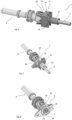
- Fig. 1 shows a connection for a fluid according to the prior art, which comprises: a pipe T, a connector C in which a fluid is intended to flow and including a housing in which pipe T is at least partially inserted, wherein pipe T and connector C are in fluidic communication.
- Pipe T and connector C are made of polymeric material and are joined together by laser welding S, which creates a cylindrical welding surface that prevents any leakage of fluid. Hydraulic tightness is entirely entrusted to weld S.
- connection 1 may be a liquid or a gas.
- Pipe 2 and connector 4 have each a respective cavity 11, 13 defining a duct in which the fluid can flow, as shown in the example of Fig. 2 .
- the cavities have a circular cross-section.
- welds 7, 9 have a continuous perimetric (annular in the example) profile.
- welds 7, 9 are arranged in a ring-like fashion around connector 4 and around pipe 2, respectively.
- the welds have a cylindrical profile.
- welds 7, 9 are made by laser welding.
- welds 7, 9 are offset relative to an axis of insertion (which is horizontal in Fig. 3 ) of pipe 2 into connector 4.
- pipe 2, connector 4 and closing element 8 are made of polymeric material.
- pipe 2 is made of polyamide.
- the areas where welds 7, 9 are made are preferably made of polymeric material.
- gasket 6 is preferably made of polymeric material.
- closing element 8 comprises a first perimetric portion 10 radially interposed between pipe 2 and connector 4.
- the first perimetric portion 10 surrounds, and optionally may be in contact with, pipe 2.
- perimetric portion 10 has a continuous or tubular profile.
- perimetric portion 10 has an annular or cylindrical shape.
- Housing 5 is a hollow portion in which a part of pipe 2 is inserted.
- housing 5 is defined by a first wall 12 with a greater internal dimension, in particular a greater inside diameter, and by a second wall 14 having a smaller internal dimension, in particular a smaller inside diameter.
- the first wall 12 is adapted to envelop the first perimetric portion 10, and the second wall 14 is adapted to envelop pipe 2.
- the first and second walls 12, 14 are concentric.
- the first and second walls 12, 14 are cylindrical.
- the first and second walls 12, 14 are in contact with the first perimetric portion 10 and, respectively, pipe 2.
- the first and second walls 12, 14 have a shape which is complementary to that of the first perimetric portion 10 and, respectively, that of pipe 2.
- gasket 6 is interposed by contact between pipe 2 and the first wall 12.
- gasket 6 is in contact with pipe 2 and with connector 4 (in particular, with housing 5).
- the first and second walls 12, 14 belong to connector 4.
- Pipe 2 may also be a tubular portion of a particular element.
- pipe 2 is straight.
- pipe 2 has a circular cross-section.
- housing 5 includes an abutment portion 16 whereon an end of pipe 2 is intended to abut, and which permits the fluid to flow through pipe 2 and connector 4 (in particular, towards a cavity 13 of connector 4).
- abutment portion 16 is a terminal part of housing 5 facing towards the inside of connector 4.
- abutment portion 16 defines a hole having a smaller diameter than housing 5, particularly than the second part 14. Abutment portion 16 acts as a stopper when pipe 2 is inserted into connector 4 during the assembly process, allowing pipe 2 to be correctly positioned relative to connector 4.
- closing element 8 comprises a second perimetric portion 18 which is radially external to connector 4, wherein the second perimetric portion 18 and connector 4 are welded together.
- a radially internal surface of the second perimetric portion 18 is welded to a radially external surface of connector 4.
- first and/or the second perimetric portions 10, 18 have a tubular, in particular cylindrical, shape.
- pipe 2 is elongated.
- connector 4 is elongated too.
- connector 4 has a tubular, in particular cylindrical, wall 20 which is radially interposed between the first and second perimetric portions 10, 18.
- the first weld 7 is made on an external face of tubular wall 20.
- Tubular wall 20 shown herein defines housing 5.
- tubular wall 20 is interposed between, and in contact with, the first and second perimetric portions 10, 18.
- Pipe 2 is inserted in a through hole of closing element 8.
- the hole is defined by surfaces whose shape is complementary to the external surface of pipe 2.
- the surfaces of the hole have a tubular, in particular cylindrical, shape.
- the through hole of closing element 8 thus defines a cylindrical cavity in which pipe 2 is inserted.
- pipe 2 partially protrudes from connector 4 and from the closing element 8.
- a first tract of pipe 2 is in contact with closing element 8
- a second tract of pipe 2 is in contact with connector 4 (in particular, with the second part 14).
- the second weld 9 is external to connector 4 with reference to the axis of insertion.
- the second weld 9 is external to housing 5.
- closing element 8 comprises a tubular, in particular cylindrical, neck 22 which is external to housing 5.
- the second weld 9 is made on such neck 22.
- Neck 22 shown herein has a shape which is complementary to pipe 2, and pipe 2 is inserted in neck 22.
- Neck 22 defines, at least partly, the through hole in which pipe 2 is inserted.
- closing element 8 and connector 4 comprise quick coupling means for mounting closing element 8 to connector 4.
- the quick coupling means include a clip-type or snap-type mechanism.
- connector 4 comprises a tooth 24 adapted to fit into an aperture 26 or recess of closing element 8.
- Tooth 24 and the aperture are configured to prevent closing element 8 from sliding off connector 4.
- aperture 26 is formed on the second perimetric portion 18, and tooth 24 is formed on a radially external portion of connector 4, in particular on tubular wall 20.
- closing element 8 and connector 4 comprise respective threaded surfaces, so that they 4, 8 can be screwed to each other. In such a case, no quick coupling means are provided.
- closing element 8 includes a stopper portion 28 whereon an end of connector 4 is intended to abut, so as to limit the mutual insertion of closing element 8 and connector 4.
- stopper portion 28 is an annular wall.
- stopper portion 28 is a wall that connects the first and second perimetric portions 10, 18.
- stopper portion 28 and the first and second perimetric portions 10, 18 form, in a longitudinal sectional view, a recess in which an end of connector 4, particularly an end of tubular wall 20, is inserted.
- connector 4 has a flare 32 at one end thereof to facilitate the insertion of closing element 8.
- closing element 8 has a flare 34 at one end thereof to facilitate the insertion of pipe 2. Flare 32 may also be useful to facilitate the insertion of pipe 2 into connector 4.
- connection 1 may optionally include a non-straight pipe 2 or a non-straight connector 4.
- Pipe 2, closing element 8 and connector 4 may have shapes and cross-sections other than those illustrated and described herein, without however departing from the scope of the present invention.
- one or more of such elements may have a polygonal, rectangular or square cross-section. Therefore, also the portions or elements identified by numerals 6, 10, 12, 14, 16, 18, 20, 22, 28 may have such shapes.
- closing element 8 has a square second perimetric portion 18.
- the various elements may also have different shapes.
- each element may have, in a sectional view, an inner surface having a shape which is different from that of the outer surface.
- connection 1 Inserting pipe 2 through closing element 8 (particularly through the through hole) so that a portion of pipe 2 protrudes from closing element 8; making weld 9 between pipe 2 and closing element 8; inserting gasket 6 into housing 5; inserting the end of pipe 2 that protrudes from closing element 8 into housing 5, through gasket 6, until the end of pipe 2 abuts on abutment portion 16 and, particularly, until tooth 24 fits into aperture 26; making weld 7 between closing element 8 and connector 4.
- connection 1 Inserting gasket 6 into housing 5; fitting closing element 8 to connector 4, particularly until tooth 24 fits into aperture 26; inserting pipe 2 into the through hole of closing element 8, until it crosses gasket 6 and abuts on abutment portion 16 of connector 4; making welds 7, 9, in particular simultaneously.
- This second assembly process offers the advantage that both welds 7, 9 can be made at the same time.
Landscapes
- Engineering & Computer Science (AREA)
- General Engineering & Computer Science (AREA)
- Mechanical Engineering (AREA)
- Branch Pipes, Bends, And The Like (AREA)
- Quick-Acting Or Multi-Walled Pipe Joints (AREA)
- Lining Or Joining Of Plastics Or The Like (AREA)
Claims (12)
- Verbindung (1) für ein Fluid, aufweisend:- ein Rohr (2),- ein Verbindungsstück (4), in dem ein Fluid fließen soll, und ein Gehäuse (5) aufweisend, in das das Rohr (2) zumindest teilweise eingesetzt ist, wobei das Rohr (2) und das Verbindungsstück (4) in Fluidverbindung stehen,- eine Dichtung (6), die in dem Gehäuse (5) angeordnet und radial zwischen dem Rohr (2) und dem Verbindungsstück (4) eingefügt ist, um jegliches Austreten von Fluid zwischen dem Rohr (2) und dem Verbindungsstück (4) zu verhindern,- ein Verschlusselement (8), in das das Rohr (2) zumindest teilweise eingesetzt ist, dadurch gekennzeichnet, dass das Verschlusselement (8) sowohl an dem Rohr (2) als auch an dem Verbindungsstück (4) mittels zweier jeweiliger Schweißnähte (9, 7) angebracht ist, die die Fluiddichtigkeit sicherstellen.
- Verbindung nach Anspruch 1, wobei die Schweißnähte (9, 7) ein kontinuierliches Umfangsprofil aufweisen.
- Verbindung nach Anspruch 1 oder 2, wobei das Rohr (2), das Verbindungsstück (4) und das Verschlusselement (8) aus einem Polymermaterial bestehen.
- Verbindung nach einem der vorhergehenden Ansprüche, wobei das Verschlusselement (8) einen ersten Umfangsabschnitt (10) aufweist, der radial zwischen dem Rohr (2) und dem Verbindungsstück (4) angeordnet ist.
- Verbindung nach Anspruch 4, wobei die Schweißnaht (9) zwischen dem Verschlusselement (8) und dem Rohr (2) an dem ersten Umfangsabschnitt (10) ausgeführt ist.
- Verbindung nach einem der Ansprüche 1 bis 4, wobei das Verschlusselement (8) einen rohrförmigen Hals (22) außerhalb des Gehäuses (5) aufweist und die Schweißnaht (9) zwischen dem Verschlusselement (8) und dem Rohr (2) an diesem Hals (22) ausgeführt ist.
- Verbindung nach einem der vorhergehenden Ansprüche, wobei das Verschlusselement (8) einen zweiten Umfangsabschnitt (18) radial außerhalb des Verbindungsstücks (4) aufweist, wobei der zweite Umfangsabschnitt (18) und das Verbindungsstück (4) miteinander verschweißt sind.
- Verbindung nach einem der vorhergehenden Ansprüche, wobei das Gehäuse (5) einen Anschlagteil (16) aufweist, an dem ein Ende des Rohrs (2) anliegen soll und der es dem Fluid ermöglicht, durch das Rohr (2) und das Verbindungsstück (4) zu fließen.
- Verbindung nach Anspruch 4, wobei das Gehäuse (5) durch eine erste Wand (12) mit einem größeren Innenmaß und eine zweite Wand (14) mit einem kleineren Innenmaß definiert ist; wobei die erste Wand (12) dazu ausgeführt ist, den ersten Umfangsabschnitt (10) zu umschließen, und die zweite Wand (14) dazu ausgeführt ist, das Rohr (2) zu umschließen.
- Verbindung nach einem der vorhergehenden Ansprüche, wobei das Verschlusselement (8) und das Verbindungsstück (4) Schnellkupplungsmittel zur Befestigung des Verschlusselements (8) an dem Verbindungsstück (4) aufweisen.
- Verbindung nach einem der vorhergehenden Ansprüche, wobei das Verbindungsstück (4) an einem Ende eine Aufweitung (32) aufweist, um das Einführen des Verschlusselements (8) in ein solches Verbindungsstück (4) zu erleichtern.
- Verbindung nach einem der vorhergehenden Ansprüche, wobei das Verschlusselement (8) an einem Ende eine Aufweitung (34) aufweist, um das Einführen des Rohrs (2) in das Verschlusselement (8) zu erleichtern.
Applications Claiming Priority (1)
| Application Number | Priority Date | Filing Date | Title |
|---|---|---|---|
| IT102021000031232A IT202100031232A1 (it) | 2021-12-14 | 2021-12-14 | Connessione per fluido con due saldature |
Publications (2)
| Publication Number | Publication Date |
|---|---|
| EP4198370A1 EP4198370A1 (de) | 2023-06-21 |
| EP4198370B1 true EP4198370B1 (de) | 2024-07-31 |
Family
ID=80461417
Family Applications (1)
| Application Number | Title | Priority Date | Filing Date |
|---|---|---|---|
| EP22212718.5A Active EP4198370B1 (de) | 2021-12-14 | 2022-12-12 | Fluidanschluss mit zwei schweissnähten |
Country Status (4)
| Country | Link |
|---|---|
| US (1) | US12013068B2 (de) |
| EP (1) | EP4198370B1 (de) |
| CN (1) | CN219169894U (de) |
| IT (1) | IT202100031232A1 (de) |
Family Cites Families (29)
| Publication number | Priority date | Publication date | Assignee | Title |
|---|---|---|---|---|
| US2933428A (en) * | 1956-03-21 | 1960-04-19 | Mueller Co | Plastic welding |
| JPS61152428A (ja) * | 1984-12-26 | 1986-07-11 | Sekisui Chem Co Ltd | 合成樹脂管の接合方法 |
| US5143407A (en) * | 1991-02-25 | 1992-09-01 | Emmet Cokeh | Pipe coupling with copper sleeve engaging copper lined pipe |
| DE9310685U1 (de) * | 1993-07-16 | 1993-09-23 | Ems-Inventa AG, Zürich | Zweiteiliger rohrverschluss aus polymeren sowie leitungssysteme aus diesem rohrverschluss und rohren aus den gleichen polymeren |
| FI102635B1 (fi) * | 1997-03-18 | 1999-01-15 | Uponor Bv | Menetelmä putkiliitoksen tekemiseksi ja putkiliitos |
| US6857670B2 (en) * | 2001-12-05 | 2005-02-22 | Cuno Incorporated | Plastic tube joint |
| DE10245355A1 (de) * | 2002-09-27 | 2004-04-08 | Degussa Ag | Rohrverbindung |
| EP1698446B1 (de) * | 2003-12-26 | 2014-09-17 | Kuraray Co., Ltd., Kurashiki Plant | Verfahren zur herstellung eines röhrenförmigen artikels |
| JP4477888B2 (ja) * | 2004-02-05 | 2010-06-09 | 本田技研工業株式会社 | 燃料タンクのチューブ接続部 |
| FR2892491B1 (fr) * | 2005-10-26 | 2009-01-16 | Legris Sa | Dispositif de raccordement a corps soude |
| US8349122B2 (en) * | 2006-05-24 | 2013-01-08 | Heateflex Corporation | Fusion welding fittings with weld bead cover |
| US7618070B2 (en) * | 2006-06-30 | 2009-11-17 | Jiffy-Tite Co, Inc. | Fluid coupling assembly |
| WO2008138709A2 (de) * | 2007-05-11 | 2008-11-20 | Voss Automotive Gmbh | Verbindungsvorrichtung für strömungsmedien |
| DE202007010502U1 (de) * | 2007-07-26 | 2008-11-27 | Voss Automotive Gmbh | Konfektionierte Medienleitung |
| JP4937236B2 (ja) * | 2008-11-26 | 2012-05-23 | 株式会社ニフコ | 燃料タンク用コネクタ、及び逆止弁 |
| WO2014205453A1 (en) * | 2013-06-22 | 2014-12-24 | Jones Mark L | Connection fitting for connecting thermoplastic pipes |
| US10006417B2 (en) * | 2014-08-06 | 2018-06-26 | Toledo Molding 7 Die, Inc. | Adaptive air intake sealing joint |
| US10794523B2 (en) * | 2015-12-14 | 2020-10-06 | Wilmarc Holdings, Llc | Laser induced sealing of concentrically layered materials |
| US10221973B2 (en) * | 2016-05-27 | 2019-03-05 | John O. Roper | Rotatable pipe adapter |
| CA3021102C (en) * | 2016-08-23 | 2021-12-14 | Rene Eduardo SIDGMAN SAITUA | Device for welded joints in pipelines |
| DE102016118578A1 (de) * | 2016-09-30 | 2018-04-05 | Veritas Ag | Fluidverbinder |
| DE102017120305A1 (de) * | 2017-09-04 | 2019-03-07 | Norma Germany Gmbh | Rohrvorrichtung mit stoffschlüssiger Verbindung |
| US11143336B1 (en) * | 2017-11-13 | 2021-10-12 | Tbl Performance Plastics, Llc | Connector, method of making connector and tubing assembly method |
| US11415257B2 (en) * | 2017-12-22 | 2022-08-16 | S & B Technical Products, Inc. | Apparatus and method for joining molecularly oriented pipe |
| US20190290896A1 (en) * | 2018-03-23 | 2019-09-26 | Flowonix Medical Incorporated | Two-stage locking catheter splice assembly |
| KR102620420B1 (ko) * | 2019-09-24 | 2024-01-03 | 다이킨 고교 가부시키가이샤 | 용착체 |
| JP7628690B2 (ja) * | 2019-10-02 | 2025-02-12 | サーパス工業株式会社 | 継手ユニットおよび継手ユニットの組立方法 |
| KR20210125669A (ko) * | 2020-04-09 | 2021-10-19 | 현대자동차주식회사 | 에어컨 배관 시스템 |
| JP2023525794A (ja) * | 2020-05-14 | 2023-06-19 | スウェージロック カンパニー | 通気口を備える2層ホース |
-
2021
- 2021-12-14 IT IT102021000031232A patent/IT202100031232A1/it unknown
-
2022
- 2022-11-29 CN CN202223217337.7U patent/CN219169894U/zh active Active
- 2022-12-07 US US18/063,049 patent/US12013068B2/en active Active
- 2022-12-12 EP EP22212718.5A patent/EP4198370B1/de active Active
Also Published As
| Publication number | Publication date |
|---|---|
| EP4198370A1 (de) | 2023-06-21 |
| CN219169894U (zh) | 2023-06-13 |
| US20230184365A1 (en) | 2023-06-15 |
| IT202100031232A1 (it) | 2023-06-14 |
| US12013068B2 (en) | 2024-06-18 |
Similar Documents
| Publication | Publication Date | Title |
|---|---|---|
| US5046765A (en) | Tubular fitting for connection of a branch pipe | |
| US4844512A (en) | Freely rotatable snap-fit connector for pipes | |
| US7404581B2 (en) | Plug-in coupling | |
| US5395140A (en) | Secondary latch and indicator for fluid coupling | |
| KR100757005B1 (ko) | 파이프 조인트 | |
| EP1909016A2 (de) | Schnellverbindungskupplung | |
| KR19990083642A (ko) | 관형 결합체 | |
| EP0971163B1 (de) | Schnellkupplungseinheit und aufnehmendes Element einer Schnellkupplungseinheit | |
| KR20210111849A (ko) | 유체 연결 장치 | |
| CN107588256A (zh) | 塑料密封配件 | |
| EP4198370B1 (de) | Fluidanschluss mit zwei schweissnähten | |
| US4809870A (en) | Inserts for fixing into openings | |
| US20200256494A1 (en) | Method of assembling a female connector of a plug-in connector | |
| US10590828B2 (en) | Exhaust gas outlet system for a motor vehicle, motor vehicle having such an exhaust gas outlet system, and method for producing an exhaust gas outlet system | |
| JPH0642685A (ja) | 流体導管結合用のプラグイン継手 | |
| US11988314B2 (en) | Male element of a fluidic coupling, fluidic coupling comprising such a male element and method for assembling such a male element | |
| US20050285392A1 (en) | Tube to hose coupling | |
| US10488119B2 (en) | Heat exchanger unit | |
| JP4588933B2 (ja) | 樹脂製パイプとタンクとの接続構造 | |
| RU2735046C1 (ru) | Система соединения поточного трубопровода | |
| NL1014716C2 (nl) | Gaspijpverbinding. | |
| IT202100031238A1 (it) | Connessione per fluido con recesso sul tubo | |
| IT202100031235A1 (it) | Connessione per fluido con una saldatura | |
| RU2773858C1 (ru) | Соединительное гнездо, соединительный узел и система охлаждения, содержащая соединительное гнездо | |
| JP2006183866A (ja) | アダプターを有する流体用クイックコネクタ |
Legal Events
| Date | Code | Title | Description |
|---|---|---|---|
| PUAI | Public reference made under article 153(3) epc to a published international application that has entered the european phase |
Free format text: ORIGINAL CODE: 0009012 |
|
| STAA | Information on the status of an ep patent application or granted ep patent |
Free format text: STATUS: THE APPLICATION HAS BEEN PUBLISHED |
|
| AK | Designated contracting states |
Kind code of ref document: A1 Designated state(s): AL AT BE BG CH CY CZ DE DK EE ES FI FR GB GR HR HU IE IS IT LI LT LU LV MC ME MK MT NL NO PL PT RO RS SE SI SK SM TR |
|
| P01 | Opt-out of the competence of the unified patent court (upc) registered |
Effective date: 20230623 |
|
| STAA | Information on the status of an ep patent application or granted ep patent |
Free format text: STATUS: REQUEST FOR EXAMINATION WAS MADE |
|
| 17P | Request for examination filed |
Effective date: 20231204 |
|
| RBV | Designated contracting states (corrected) |
Designated state(s): AL AT BE BG CH CY CZ DE DK EE ES FI FR GB GR HR HU IE IS IT LI LT LU LV MC ME MK MT NL NO PL PT RO RS SE SI SK SM TR |
|
| GRAP | Despatch of communication of intention to grant a patent |
Free format text: ORIGINAL CODE: EPIDOSNIGR1 |
|
| STAA | Information on the status of an ep patent application or granted ep patent |
Free format text: STATUS: GRANT OF PATENT IS INTENDED |
|
| RIC1 | Information provided on ipc code assigned before grant |
Ipc: F16L 47/02 20060101AFI20240311BHEP |
|
| INTG | Intention to grant announced |
Effective date: 20240327 |
|
| GRAS | Grant fee paid |
Free format text: ORIGINAL CODE: EPIDOSNIGR3 |
|
| GRAA | (expected) grant |
Free format text: ORIGINAL CODE: 0009210 |
|
| STAA | Information on the status of an ep patent application or granted ep patent |
Free format text: STATUS: THE PATENT HAS BEEN GRANTED |
|
| AK | Designated contracting states |
Kind code of ref document: B1 Designated state(s): AL AT BE BG CH CY CZ DE DK EE ES FI FR GB GR HR HU IE IS IT LI LT LU LV MC ME MK MT NL NO PL PT RO RS SE SI SK SM TR |
|
| REG | Reference to a national code |
Ref country code: CH Ref legal event code: EP Ref country code: GB Ref legal event code: FG4D |
|
| REG | Reference to a national code |
Ref country code: DE Ref legal event code: R096 Ref document number: 602022004985 Country of ref document: DE |
|
| REG | Reference to a national code |
Ref country code: IE Ref legal event code: FG4D |
|
| REG | Reference to a national code |
Ref country code: LT Ref legal event code: MG9D |
|
| REG | Reference to a national code |
Ref country code: NL Ref legal event code: MP Effective date: 20240731 |
|
| PG25 | Lapsed in a contracting state [announced via postgrant information from national office to epo] |
Ref country code: PT Free format text: LAPSE BECAUSE OF FAILURE TO SUBMIT A TRANSLATION OF THE DESCRIPTION OR TO PAY THE FEE WITHIN THE PRESCRIBED TIME-LIMIT Effective date: 20241202 |
|
| REG | Reference to a national code |
Ref country code: AT Ref legal event code: MK05 Ref document number: 1708752 Country of ref document: AT Kind code of ref document: T Effective date: 20240731 |
|
| PG25 | Lapsed in a contracting state [announced via postgrant information from national office to epo] |
Ref country code: PT Free format text: LAPSE BECAUSE OF FAILURE TO SUBMIT A TRANSLATION OF THE DESCRIPTION OR TO PAY THE FEE WITHIN THE PRESCRIBED TIME-LIMIT Effective date: 20241202 |
|
| PG25 | Lapsed in a contracting state [announced via postgrant information from national office to epo] |
Ref country code: NO Free format text: LAPSE BECAUSE OF FAILURE TO SUBMIT A TRANSLATION OF THE DESCRIPTION OR TO PAY THE FEE WITHIN THE PRESCRIBED TIME-LIMIT Effective date: 20241031 |
|
| PG25 | Lapsed in a contracting state [announced via postgrant information from national office to epo] |
Ref country code: GR Free format text: LAPSE BECAUSE OF FAILURE TO SUBMIT A TRANSLATION OF THE DESCRIPTION OR TO PAY THE FEE WITHIN THE PRESCRIBED TIME-LIMIT Effective date: 20241101 Ref country code: NL Free format text: LAPSE BECAUSE OF FAILURE TO SUBMIT A TRANSLATION OF THE DESCRIPTION OR TO PAY THE FEE WITHIN THE PRESCRIBED TIME-LIMIT Effective date: 20240731 Ref country code: FI Free format text: LAPSE BECAUSE OF FAILURE TO SUBMIT A TRANSLATION OF THE DESCRIPTION OR TO PAY THE FEE WITHIN THE PRESCRIBED TIME-LIMIT Effective date: 20240731 Ref country code: PL Free format text: LAPSE BECAUSE OF FAILURE TO SUBMIT A TRANSLATION OF THE DESCRIPTION OR TO PAY THE FEE WITHIN THE PRESCRIBED TIME-LIMIT Effective date: 20240731 |
|
| PG25 | Lapsed in a contracting state [announced via postgrant information from national office to epo] |
Ref country code: BG Free format text: LAPSE BECAUSE OF FAILURE TO SUBMIT A TRANSLATION OF THE DESCRIPTION OR TO PAY THE FEE WITHIN THE PRESCRIBED TIME-LIMIT Effective date: 20240731 |
|
| PG25 | Lapsed in a contracting state [announced via postgrant information from national office to epo] |
Ref country code: LV Free format text: LAPSE BECAUSE OF FAILURE TO SUBMIT A TRANSLATION OF THE DESCRIPTION OR TO PAY THE FEE WITHIN THE PRESCRIBED TIME-LIMIT Effective date: 20240731 |
|
| PG25 | Lapsed in a contracting state [announced via postgrant information from national office to epo] |
Ref country code: AT Free format text: LAPSE BECAUSE OF FAILURE TO SUBMIT A TRANSLATION OF THE DESCRIPTION OR TO PAY THE FEE WITHIN THE PRESCRIBED TIME-LIMIT Effective date: 20240731 Ref country code: IS Free format text: LAPSE BECAUSE OF FAILURE TO SUBMIT A TRANSLATION OF THE DESCRIPTION OR TO PAY THE FEE WITHIN THE PRESCRIBED TIME-LIMIT Effective date: 20241130 |
|
| PG25 | Lapsed in a contracting state [announced via postgrant information from national office to epo] |
Ref country code: HR Free format text: LAPSE BECAUSE OF FAILURE TO SUBMIT A TRANSLATION OF THE DESCRIPTION OR TO PAY THE FEE WITHIN THE PRESCRIBED TIME-LIMIT Effective date: 20240731 |
|
| PG25 | Lapsed in a contracting state [announced via postgrant information from national office to epo] |
Ref country code: ES Free format text: LAPSE BECAUSE OF FAILURE TO SUBMIT A TRANSLATION OF THE DESCRIPTION OR TO PAY THE FEE WITHIN THE PRESCRIBED TIME-LIMIT Effective date: 20240731 Ref country code: RS Free format text: LAPSE BECAUSE OF FAILURE TO SUBMIT A TRANSLATION OF THE DESCRIPTION OR TO PAY THE FEE WITHIN THE PRESCRIBED TIME-LIMIT Effective date: 20241031 |
|
| PG25 | Lapsed in a contracting state [announced via postgrant information from national office to epo] |
Ref country code: RS Free format text: LAPSE BECAUSE OF FAILURE TO SUBMIT A TRANSLATION OF THE DESCRIPTION OR TO PAY THE FEE WITHIN THE PRESCRIBED TIME-LIMIT Effective date: 20241031 Ref country code: PL Free format text: LAPSE BECAUSE OF FAILURE TO SUBMIT A TRANSLATION OF THE DESCRIPTION OR TO PAY THE FEE WITHIN THE PRESCRIBED TIME-LIMIT Effective date: 20240731 Ref country code: NO Free format text: LAPSE BECAUSE OF FAILURE TO SUBMIT A TRANSLATION OF THE DESCRIPTION OR TO PAY THE FEE WITHIN THE PRESCRIBED TIME-LIMIT Effective date: 20241031 Ref country code: NL Free format text: LAPSE BECAUSE OF FAILURE TO SUBMIT A TRANSLATION OF THE DESCRIPTION OR TO PAY THE FEE WITHIN THE PRESCRIBED TIME-LIMIT Effective date: 20240731 Ref country code: LV Free format text: LAPSE BECAUSE OF FAILURE TO SUBMIT A TRANSLATION OF THE DESCRIPTION OR TO PAY THE FEE WITHIN THE PRESCRIBED TIME-LIMIT Effective date: 20240731 Ref country code: IS Free format text: LAPSE BECAUSE OF FAILURE TO SUBMIT A TRANSLATION OF THE DESCRIPTION OR TO PAY THE FEE WITHIN THE PRESCRIBED TIME-LIMIT Effective date: 20241130 Ref country code: HR Free format text: LAPSE BECAUSE OF FAILURE TO SUBMIT A TRANSLATION OF THE DESCRIPTION OR TO PAY THE FEE WITHIN THE PRESCRIBED TIME-LIMIT Effective date: 20240731 Ref country code: GR Free format text: LAPSE BECAUSE OF FAILURE TO SUBMIT A TRANSLATION OF THE DESCRIPTION OR TO PAY THE FEE WITHIN THE PRESCRIBED TIME-LIMIT Effective date: 20241101 Ref country code: FI Free format text: LAPSE BECAUSE OF FAILURE TO SUBMIT A TRANSLATION OF THE DESCRIPTION OR TO PAY THE FEE WITHIN THE PRESCRIBED TIME-LIMIT Effective date: 20240731 Ref country code: ES Free format text: LAPSE BECAUSE OF FAILURE TO SUBMIT A TRANSLATION OF THE DESCRIPTION OR TO PAY THE FEE WITHIN THE PRESCRIBED TIME-LIMIT Effective date: 20240731 Ref country code: BG Free format text: LAPSE BECAUSE OF FAILURE TO SUBMIT A TRANSLATION OF THE DESCRIPTION OR TO PAY THE FEE WITHIN THE PRESCRIBED TIME-LIMIT Effective date: 20240731 Ref country code: AT Free format text: LAPSE BECAUSE OF FAILURE TO SUBMIT A TRANSLATION OF THE DESCRIPTION OR TO PAY THE FEE WITHIN THE PRESCRIBED TIME-LIMIT Effective date: 20240731 |
|
| PG25 | Lapsed in a contracting state [announced via postgrant information from national office to epo] |
Ref country code: RO Free format text: LAPSE BECAUSE OF FAILURE TO SUBMIT A TRANSLATION OF THE DESCRIPTION OR TO PAY THE FEE WITHIN THE PRESCRIBED TIME-LIMIT Effective date: 20240731 Ref country code: SM Free format text: LAPSE BECAUSE OF FAILURE TO SUBMIT A TRANSLATION OF THE DESCRIPTION OR TO PAY THE FEE WITHIN THE PRESCRIBED TIME-LIMIT Effective date: 20240731 Ref country code: DK Free format text: LAPSE BECAUSE OF FAILURE TO SUBMIT A TRANSLATION OF THE DESCRIPTION OR TO PAY THE FEE WITHIN THE PRESCRIBED TIME-LIMIT Effective date: 20240731 |
|
| PG25 | Lapsed in a contracting state [announced via postgrant information from national office to epo] |
Ref country code: EE Free format text: LAPSE BECAUSE OF FAILURE TO SUBMIT A TRANSLATION OF THE DESCRIPTION OR TO PAY THE FEE WITHIN THE PRESCRIBED TIME-LIMIT Effective date: 20240731 |
|
| PG25 | Lapsed in a contracting state [announced via postgrant information from national office to epo] |
Ref country code: CZ Free format text: LAPSE BECAUSE OF FAILURE TO SUBMIT A TRANSLATION OF THE DESCRIPTION OR TO PAY THE FEE WITHIN THE PRESCRIBED TIME-LIMIT Effective date: 20240731 |
|
| PG25 | Lapsed in a contracting state [announced via postgrant information from national office to epo] |
Ref country code: SK Free format text: LAPSE BECAUSE OF FAILURE TO SUBMIT A TRANSLATION OF THE DESCRIPTION OR TO PAY THE FEE WITHIN THE PRESCRIBED TIME-LIMIT Effective date: 20240731 |
|
| PGFP | Annual fee paid to national office [announced via postgrant information from national office to epo] |
Ref country code: IT Payment date: 20241231 Year of fee payment: 3 |
|
| REG | Reference to a national code |
Ref country code: DE Ref legal event code: R097 Ref document number: 602022004985 Country of ref document: DE |
|
| PLBE | No opposition filed within time limit |
Free format text: ORIGINAL CODE: 0009261 |
|
| STAA | Information on the status of an ep patent application or granted ep patent |
Free format text: STATUS: NO OPPOSITION FILED WITHIN TIME LIMIT |
|
| PG25 | Lapsed in a contracting state [announced via postgrant information from national office to epo] |
Ref country code: MC Free format text: LAPSE BECAUSE OF FAILURE TO SUBMIT A TRANSLATION OF THE DESCRIPTION OR TO PAY THE FEE WITHIN THE PRESCRIBED TIME-LIMIT Effective date: 20240731 |
|
| 26N | No opposition filed |
Effective date: 20250501 |
|
| PG25 | Lapsed in a contracting state [announced via postgrant information from national office to epo] |
Ref country code: LU Free format text: LAPSE BECAUSE OF NON-PAYMENT OF DUE FEES Effective date: 20241212 |
|
| PG25 | Lapsed in a contracting state [announced via postgrant information from national office to epo] |
Ref country code: SE Free format text: LAPSE BECAUSE OF FAILURE TO SUBMIT A TRANSLATION OF THE DESCRIPTION OR TO PAY THE FEE WITHIN THE PRESCRIBED TIME-LIMIT Effective date: 20240731 |
|
| REG | Reference to a national code |
Ref country code: BE Ref legal event code: MM Effective date: 20241231 |
|
| PG25 | Lapsed in a contracting state [announced via postgrant information from national office to epo] |
Ref country code: BE Free format text: LAPSE BECAUSE OF NON-PAYMENT OF DUE FEES Effective date: 20241231 |
|
| PGFP | Annual fee paid to national office [announced via postgrant information from national office to epo] |
Ref country code: FR Payment date: 20250930 Year of fee payment: 4 |
|
| PG25 | Lapsed in a contracting state [announced via postgrant information from national office to epo] |
Ref country code: IE Free format text: LAPSE BECAUSE OF NON-PAYMENT OF DUE FEES Effective date: 20241212 |
|
| PGFP | Annual fee paid to national office [announced via postgrant information from national office to epo] |
Ref country code: DE Payment date: 20250930 Year of fee payment: 4 |