EP4198366B1 - Rohrverbindungsteil zum verbinden der spitzenden zweier rohre - Google Patents
Rohrverbindungsteil zum verbinden der spitzenden zweier rohre Download PDFInfo
- Publication number
- EP4198366B1 EP4198366B1 EP22213670.7A EP22213670A EP4198366B1 EP 4198366 B1 EP4198366 B1 EP 4198366B1 EP 22213670 A EP22213670 A EP 22213670A EP 4198366 B1 EP4198366 B1 EP 4198366B1
- Authority
- EP
- European Patent Office
- Prior art keywords
- connection part
- pipe connection
- pipe
- annular
- pipes
- Prior art date
- Legal status (The legal status is an assumption and is not a legal conclusion. Google has not performed a legal analysis and makes no representation as to the accuracy of the status listed.)
- Active
Links
Images


Classifications
-
- F—MECHANICAL ENGINEERING; LIGHTING; HEATING; WEAPONS; BLASTING
- F16—ENGINEERING ELEMENTS AND UNITS; GENERAL MEASURES FOR PRODUCING AND MAINTAINING EFFECTIVE FUNCTIONING OF MACHINES OR INSTALLATIONS; THERMAL INSULATION IN GENERAL
- F16L—PIPES; JOINTS OR FITTINGS FOR PIPES; SUPPORTS FOR PIPES, CABLES OR PROTECTIVE TUBING; MEANS FOR THERMAL INSULATION IN GENERAL
- F16L21/00—Joints with sleeve or socket
- F16L21/02—Joints with sleeve or socket with elastic sealing rings between pipe and sleeve or between pipe and socket, e.g. with rolling or other prefabricated profiled rings
- F16L21/03—Joints with sleeve or socket with elastic sealing rings between pipe and sleeve or between pipe and socket, e.g. with rolling or other prefabricated profiled rings placed in the socket before connection
Definitions
- the invention relates to a pipe connection part for connecting the spigot ends of two pipes, wherein the pipe connection part has two socket areas, wherein each socket area is designed to receive a pipe spigot end and has an insertion opening for inserting the pipe spigot ends, wherein between the socket areas of the pipe connection part an annular web is arranged which runs along the inner wall transversely to the longitudinal extent of the pipe connection part.
- Double sockets can, for example, be essentially hollow cylindrical and have insertion openings on both sides into which the spigot ends of two pipes can be inserted.
- the inner diameter of the double socket is adapted to the outer diameter of the pipes to be connected.
- annular web extending radially from the inner wall of the double socket can be arranged inside a double socket.
- the two side walls of the annular web can serve as a lateral stop for the pipes to be connected, preventing one pipe from being pushed too far into the double socket and causing the other pipe to be pushed out of the double socket.
- Such a ring web can be disadvantageous when the pipes are subjected to lateral loading, for example when laying the pipes in a In a bend, the pipes are pressed together on the inside of the bend, while the pipe spigots are pulled apart on the outside. This creates a gap between the ring web and the pipe spigots. Dirt particles or similar can accumulate in this gap. Furthermore, the tightness of the pipe connection can no longer be fully guaranteed. Furthermore, lateral loading creates significant stress, which can damage the coupling.
- a two-ended splicer includes an outer sleeve having an inwardly directed bar between its ends.
- An inner bracket for each pile end is supported by the bar and is spaced from the outer sleeve to receive the end of the pile therebetween.
- the DE 197 18 282 A1 shows an arrangement for connecting two pipes with a socket that is double-walled at both ends and has a smooth inner surface.
- the pipe ends are inserted with their front edges into the gaps between the outer and inner walls. This connection allows for length compensation due to temperature fluctuations and avoids disruptive annular spaces on the inside of the connection point.
- the EP 2 085 673 A1 refers to a pipe connection structure comprising a socket member having an end edge adapted to receive a spigot end of a pipe, the socket member having a wall in which a circumferential seal ring groove is provided. A seal ring is disposed in the seal ring groove and, when the spigot end is received in the socket member, is in a compressed sealing state to seal the connection between the socket member and the spigot end.
- the invention is based on the object of proposing a pipe connection part for connecting two pipes in which no open gap is created between the pipes even under lateral load and a high load capacity is ensured when laying bends.
- a pipe connection part for connecting the spigot ends of two pipes
- the pipe connection part has two socket areas, wherein each socket area is designed to receive a pipe spigot end and has an insertion opening for inserting the pipe spigot ends
- an annular web is arranged between the socket areas of the pipe connection part, which runs circumferentially along the inner wall transversely to the longitudinal extent of the pipe connection part, wherein the circumferential annular web has an inner sleeve extending on both sides in the direction of the insertion openings, wherein between the inner sleeve, the side walls of the annular web and sections of the inner wall of the pipe connection part on both sides of the annular web there is formed a circumferential receiving space for at least partially receiving the respective pipe spigot ends
- the socket areas each have at least one circumferential annular bead for receiving at least one annular seal, wherein the outer sides of the annular bead, in particular the outer side of the bead base, at least in sections form a circumferential annul
- the pipe connection part for connecting the spigot ends of two pipes is designed in the form of a double socket, i.e. for receiving pipe ends on both sides.
- the pipe connection part has a substantially hollow-cylindrical interior into which the spigot ends of the pipes can be inserted from both sides.
- the pipe connection part is designed such that two pipes can be connected such that their longitudinal axes of symmetry essentially coincide.
- the pipe connection part has two socket areas that extend on both sides from a central area and each have an insertion opening through which the pipes to be connected can be inserted from both sides.
- the insertion openings of the two adjacent socket areas are preferably radially symmetrical, and the central axes of symmetry of the two insertion openings essentially coincide.
- An annular web is arranged on the inner wall of the pipe connection part and extends radially from the inner wall towards the interior of the pipe connection part.
- the annular web thus preferably has the shape of a circular ring.
- the pipe connection part can be mirror-symmetrical and rotationally symmetrical.
- the annular web is arranged in the region of the central axis of symmetry, which runs perpendicular to the longitudinal extent of the pipe connection part.
- the side surfaces of the annular web each face an insertion opening and are substantially parallel to the axis defined by the radius of the inner wall of the
- the inner radius of the annular web is arranged rotationally symmetrically around the cylinder axis, around which the interior of the pipe connection part is rotationally symmetrical.
- the cylinder axis corresponds to the longitudinal axis of the pipe connection part.
- An inner sleeve is arranged on the inner radius of the annular web, extending on both sides in the direction of the insertion openings.
- the sleeve is thus arranged transversely to the annular plane spanned by the annular web.
- the sleeve is therefore arranged on the web in the form of a belt, like a T-beam.
- the inner sleeve thus forms a projection that projects beyond the side walls of the annular web on both sides, i.e. in the direction of the insertion openings.
- the width of the inner sleeve i.e.
- the dimension of the inner sleeve in the longitudinal extension of the pipe connection part is preferably approximately one sixth of the diameter of the pipes to be connected.
- a receiving space is formed along the annular web to accommodate the pipe spigot ends of the pipes to be connected.
- the receiving spaces are each open in the direction of the insertion openings so that the pipe spigot ends can be inserted.
- the gap between the pipe spigot ends and the annular web is covered or bridged by the inner sleeve.
- the inner diameter of the sleeve can correspond to the inner diameter of the pipes to be joined.
- the spigot ends of the pipes to be joined can be tapered accordingly.
- the pipe connection piece is preferably made of a single piece of plastic.
- the socket areas each have a circumferential annular bead for receiving at least one annular seal.
- the socket areas each have at least one annular bead, into which a ring seal can be inserted.
- a seal received in the annular bead is provided in particular for sealing the connection between the pipes.
- the annular beads can each be arranged adjacent to the respective socket neck.
- An annular bead is designed in particular as a recess in the inner wall of the pipe connection part.
- the imaginary plane spanned by an annular bead is arranged parallel to a plane spanned by the diameter of the pipe connection part.
- the annular beads are thus arranged transversely to the longitudinal extent, i.e. to the cylinder axis of the pipe connection part.
- the annular beads for receiving the ring seals are essentially groove-like.
- the groove base or the bead base has an outer wall which forms a circumferential rib on the outside of the pipe connection part.
- the rib is arranged parallel to the reinforcing ribs formed on the outside.
- the rib formed by the bead base can be wider than the reinforcing ribs.
- the rib formed by the outer side of the annular bead has a smaller outer diameter than the adjacent reinforcing rib located further toward the receiving opening, and the rib formed by the outer side of the annular bead has a larger outer diameter than the adjacent reinforcing rib located further toward the center of the pipe connection piece.
- the outer diameters of the ribs formed by the annular beads on the outer side of the pipe connection piece thus fit into the outer diameters of the reinforcing ribs, which decrease from the outside to the inside. This enables favorable force distribution, particularly when installing in curves.
- the inner sleeve extending on both sides is arranged circumferentially along the inner radius of the annular web, and a circumferential undercut is formed on both sides of the annular web by the inner sleeve arranged on the annular web.
- the inner sleeve is arranged circumferentially in the form of a projection along the inner radius of the annular web.
- the inner diameter of the inner sleeve corresponds to the inner diameter of the pipes to be connected.
- the pipes to be connected can have their spigot ends chamfered or tapered on both sides.
- the tapered areas can be accommodated between the sleeve and the inner wall of the pipe connection piece, while the front edges of the pipes can be brought into contact with the side walls of the annular web.
- the pipe spigot ends and their tapered sections can be adapted to the receiving spaces between the inner sleeve and the inner wall of the pipe connection piece, so that when two pipes are joined, the inner surface between the pipes and the sleeve is as flat as possible, with the inner wall of the pipes merging into the inside of the sleeve.
- the inner diameter of the inner sleeve therefore corresponds to the nominal inner diameter of the pipes to be connected.
- the inner sleeve is bevelled at the edges facing the insertion openings, wherein the bevel is formed on the side of the projection facing away from the inner wall of the pipe connection part, and wherein the material thickness of the inner sleeve decreases, at least in sections, towards the outer edges of the inner sleeve.
- the inner sleeve i.e. the projection on both sides arranged on the annular web, has a bevel on its side facing away from the inner wall of the pipe connection part, i.e. on the side facing the interior, i.e. the longitudinal axis.
- the material thickness i.e.
- the thickness of the inner sleeve is less on the outer edges facing the insertion openings than in the area at the annular web.
- the material thickness of the inner sleeve decreases towards its outer edges, with a bevel being formed in the direction of the inner wall of the pipe connection part. This results in improved joining of the pipes to be connected and an improved formation of an inner surface between the pipes and the inner sleeve with a surface line that is as straight as possible.
- the bevel at the outer edges of the inner sleeve transitions into a curve.
- the inner sleeve which is beveled at the outer areas, transitions into a curve at its outer edges, so that the outer edges facing the insertion openings form a radius. This facilitates the joining of the pipe spigot ends to be connected.
- At least one reinforcing element is formed between the side walls of the annular web and the inner sleeve.
- a reinforcing element in the form of a thickened portion of the annular web is formed between the sides of the inner sleeve facing the inner wall of the pipe connection part and the side walls of the annular web.
- the thickened portion of the annular web can be adapted, in particular, to the bevels, in particular the inner bevels, of the pipe spigot ends to be joined.
- the reinforcement element is designed to correspond to the bevels of the pipe spigots to be inserted.
- the pipe spigots of the pipes to be joined each have an outer and inner bevel on their outer and inner edges.
- the reinforcement elements between the side walls of the annular web and the respective projecting area of the inner sleeve can be adapted to the inner bevel of the pipe spigots, thus enabling easy joining of the pipe spigots.
- the sections of the inner wall of the pipe connection part that define the receiving space correspond to the outer diameters of the pipes to be accommodated.
- a receiving space is formed on both sides of the annular web to accommodate the spigot ends of the pipes to be joined.
- the outer diameter of a The receiving space provided by the inner wall of the pipe connection part in this area corresponds to the outer diameter of the spigot ends of the pipes to be connected.
- the pipe spigot ends can be pressed into the receiving spaces. This ensures that the pipe spigot ends are securely held between the inside of the inner sleeve and the outer wall of the pipe connection part.
- the pipe spigot ends can have inner tapers.
- the inner diameter of the receiving spaces which is formed by the side of the inner sleeve facing the inner wall of the pipe connection part, can correspond to the inner diameter of the pipe spigot ends in the area of the inner tapers.
- the outer diameter of the pipe spigot ends can correspond to the inner diameter of the inner wall of the pipe connection part in this area.
- the inner diameter of the pipe connection part is larger at the openings of the receiving spaces than in the areas of the receiving spaces adjacent to the annular web.
- the receiving spaces extending on both sides of the annular web each have a receiving opening which is aligned towards the insertion openings.
- the pipe connection part In a first area, which is arranged adjacent to the openings of the insertion spaces, i.e. in the area opposite the outer edges of the inner sleeve, the pipe connection part has a larger inner diameter than in a second area of the receiving space which is arranged directly adjacent to the annular web.
- the pipe connection part has external ribs, the ribs extend in the radial direction from the outer wall of the pipe connection part and the ribs are arranged parallel to each other.
- the pipe connection part has external ribs, which are designed in particular as reinforcing ribs.
- the ribs serve to stiffen and reinforce the pipe connection part during the deformation of the socket areas after joining the pipes and subsequent bending, when the pipes are laid in curves.
- the ribs extend in a radial direction on the outside, for example the outer surface of the pipe connection part.
- the imaginary planes spanned by the ribs are arranged parallel to one another and parallel to the plane spanned by the inner diameter of the pipe connection part.
- the ribs thus run transversely to the longitudinal extent of the pipe connection part.
- the ribs are preferably formed in one piece with the pipe connection part, in particular from a plastic.
- the ribs and the pipe connection part can be formed in two parts or in multiple parts.
- the ribs on the outer socket areas can be formed on a sleeve-like component, which can be arranged around the socket areas.
- the ribs can be formed on an outer sleeve part, the inner wall of which is essentially hollow-cylindrical.
- the outer regions of the socket regions can also be essentially cylindrical, so that the outer sleeves with the ribs are pushed, in particular pressed, over the socket regions.
- the socket regions can have undercuts, so that a secure fixation of the outer sleeves in the longitudinal direction of the pipe connection part is possible.
- the outer sleeves with ribs can be made of a different material than the pipe connection part, for example, of a metallic material such as aluminum, but they can also be made of the same material as the pipe connection part.
- the ribs on the outer sleeves also extend in the radial direction to the outer surface of the pipe connection part when assembled. The reinforcing ribs on the outer side enable a significant increase in the stability of the pipe connection part, particularly during Deformations may occur due to curved pipe layouts.
- the ribs in the area of the outer wall of the insertion openings have a larger outer diameter than the ribs in the middle area of the connecting part.
- the outer ribs i.e. the ribs in the area of the insertion openings, have the largest outer diameters.
- the outer diameters of the adjacent ribs decrease towards the center, i.e. in the direction of the mirror symmetry axis in which the annular web is arranged.
- the ribs with the largest outer diameters are arranged in the area of the insertion openings, while the ribs with the smallest outer diameters are arranged adjacent to the center, i.e. to the annular web.
- the different outer diameters ensure improved force distribution when inserting the pipes to be connected.
- the outer diameters of the parallel ribs decrease from the insertion openings toward the center of the pipe connection piece.
- the contour of the outer diameters ensures a good distribution of the forces occurring when laying the pipes around curves and when inserting the pipes into the pipe connection piece.
- the socket areas each have a socket neck, and the socket necks each have a length of approximately one-third of the diameter of the pipe to be accommodated.
- the socket necks are the entry areas, starting from the respective insertion opening and extending towards the center of the pipe connection part.
- the socket necks are essentially hollow-cylindrical and have an inner surface with a straight surface line.
- the socket necks are particularly used to guide the pipes to be connected and to stabilize the
- the pipe connection part is designed to fit the connected pipes when bending.
- the inner diameter of the inner wall of the socket necks approximately corresponds to the outer diameter of the pipes to be connected.
- the inner sleeve has an inclination on both sides of the annular web toward the nearest inner wall of the pipe connection piece.
- the lateral projections of the annular web forming an inner sleeve are each slightly inclined toward the nearest inner wall of the pipe connection piece, i.e., the inner wall that also defines the respective receiving space. This ensures a secure hold when inserting the pipe spigot ends.
- the annular bead is designed to be flexible, at least in sections. Due to the formation of a rib on the outer wall and the resulting relatively thin wall thickness of the bead and the bead base, the annular beads are designed to be flexible, allowing the bead base to be stretched and compressed. The wall thickness is less than in the case where the bead is a recess in a solid component.
- the distance in the longitudinal extension of the pipe connection part between the outer side of the annular bead facing the insertion end and the center of the annular web corresponds approximately to one-third of the pipe diameter of the pipes to be accommodated.
- the distance between the annular bead and the annular web, i.e., the axis of symmetry of the pipe connection part ensures secure pipe accommodation and force distribution when laying the pipes in curves.
- the pipe connection part is constructed with mirror symmetry and/or rotational symmetry.
- the pipe connection part is constructed with mirror symmetry to the axis of symmetry, which preferably coincides with the web, and rotational symmetry about a cylinder axis.
- FIG. 1 A pipe connection part 1 with two socket areas 2, 3 is shown.
- the socket areas 2, 3 each have insertion openings 4, 5 for inserting pipe spigots.
- a circumferential annular web 6 is arranged, which runs along the inner wall 7 of the pipe connection part 1 and extends radially from the inner wall 7.
- the annular web 6 has an inner sleeve 8 on its outer radius, which is designed in the form of projections extending in the direction of the insertion openings 4, 5.
- receiving spaces 11, 12 are formed for receiving pipe spigot ends of the pipes to be inserted.
- the annular web 6 is aligned along a mirror symmetry axis 13.
- the pipe connection part 1 is essentially cylindrical and radially symmetrical about a longitudinal axis 14.
- the inner sleeve 8 has bevels 15, 16 on its outer edges facing the insertion openings 4, 5, which taper to a radius 17, 18, forming a rounded edge of the inner sleeve 8.
- the socket areas 2, 3 each have an annular bead 19, 20, into which an annular seal can be accommodated.
- Reinforcing elements 21, 22 are formed between the side walls 9, 10 of the annular web 6. The reinforcing elements 21, 22 can be adapted, in particular, to the inner bevel of a pipe spigot end.
- the receiving spaces 11, 12 for receiving the pipe spigot ends each have a first region 23, 24 in which the inner radius of the inner wall 7 is larger than in a second region 25, 26.
- the width of the second region 25, 26 is approximately 3 ⁇ 4 of the width of the respective receiving space 11, 12 and serves to center the respective pipe spigot end to be accommodated.
- the inner edges 27, 28 of the insertion openings 4, 5 are rounded to ensure easy insertion of the pipes to be accommodated.
- Reinforcing ribs 30 are arranged on the outer side 29 of the pipe connecting part 1, wherein the outer diameters of the reinforcing ribs and thus the height of the ribs relative to their base decrease from the insertion openings 4, 5 in the direction of the mirror symmetry axis 13.
- the outer sides 31, 32 of the annular beads 19, 20 each form a rib 33, 34.
- the distance defining the socket neck 51, 52 between an insertion opening 4, 5 and an annular bead 19, 20 is approximately 1 ⁇ 3 of the nominal diameter of the pipes to be connected.
- Fig. 2 is a pipe connection part 1 according to Fig. 1 with inserted pipes 35, 36. Identical components are provided with the same reference numerals.
- the pipes 35, 36 are received in the receiving spaces 11, 12.
- the pipe spigot ends 37, 38 each have an inner bevel 39, 40.
- the pipe spigot ends 37, 38 have a tapered area 41, 42 in which the inner radius of the pipe is larger than the nominal diameter.
- the area 41, 42 is adapted to the dimensions of the receiving space 11, 12.
- the inner diameter 43 of the pipes 35, 36 corresponds to the inner diameter 44 of the circumferential inner sleeve 8.
- Fig. 3 is a pipe connection part 1 according to the Fig. 1 and 2 when laying the pipes 35, 36 in a curve. Identical components are provided with the same reference numerals.
- the outer wall 29 of the pipe connection part 1 is stretched.
- the outer sides 31, 32 of the annular beads 19, 20 are also stretched. Because the annular beads 19, 20 are designed as ribs 33, 34, the outer sides of the annular beads 31, 32 can be stretched so that the pipe connection part 1 is not damaged by the curved laying of the pipes 35, 36 is damaged. On the inside of the curve 47, the annular beads 31, 32 are compressed accordingly, whereby the acting forces can be absorbed.
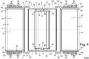
- Fig. 4 1 shows a pipe connection part 1 with outer sleeves 53, 54 having ribs 30.
- the outer sleeves 53, 54 have a hollow cylindrical inner wall that is pushed over the outer areas of the socket necks 51, 52.
- the outer sleeves 53, 54 can be pressed over the socket necks 51, 52.
- the socket necks 51, 52 can have undercuts 55, 56 that enable secure assembly of the outer sleeves 53, 54.
- the undercuts 55, 56 can be designed such that slipping of the outer sleeves 53, 54 in the longitudinal direction of the pipe connection part 1 is prevented.
- the outer sleeves 53, 54 can be made of a metallic material, such as aluminum, or of a plastic.
- the plastic can be the same plastic from which the pipe connection part 1 is made, but other materials can also be used.
Landscapes
- Engineering & Computer Science (AREA)
- General Engineering & Computer Science (AREA)
- Mechanical Engineering (AREA)
- Quick-Acting Or Multi-Walled Pipe Joints (AREA)
- Joints With Sleeves (AREA)
- Mutual Connection Of Rods And Tubes (AREA)
- Rigid Pipes And Flexible Pipes (AREA)
Priority Applications (1)
| Application Number | Priority Date | Filing Date | Title |
|---|---|---|---|
| RS20250961A RS67255B1 (sr) | 2021-12-17 | 2022-12-15 | Spojni deo cevi za spajanje krajeva dveju cevi |
Applications Claiming Priority (1)
| Application Number | Priority Date | Filing Date | Title |
|---|---|---|---|
| DE202021106891.4U DE202021106891U1 (de) | 2021-12-17 | 2021-12-17 | Rohrverbindungsteil zum Verbinden der Spitzenden zweier Rohre |
Publications (3)
| Publication Number | Publication Date |
|---|---|
| EP4198366A1 EP4198366A1 (de) | 2023-06-21 |
| EP4198366C0 EP4198366C0 (de) | 2025-06-25 |
| EP4198366B1 true EP4198366B1 (de) | 2025-06-25 |
Family
ID=80221176
Family Applications (1)
| Application Number | Title | Priority Date | Filing Date |
|---|---|---|---|
| EP22213670.7A Active EP4198366B1 (de) | 2021-12-17 | 2022-12-15 | Rohrverbindungsteil zum verbinden der spitzenden zweier rohre |
Country Status (5)
| Country | Link |
|---|---|
| EP (1) | EP4198366B1 (pl) |
| DE (1) | DE202021106891U1 (pl) |
| ES (1) | ES3042408T3 (pl) |
| PL (1) | PL4198366T4 (pl) |
| RS (1) | RS67255B1 (pl) |
Family Cites Families (5)
| Publication number | Priority date | Publication date | Assignee | Title |
|---|---|---|---|---|
| DE1937176A1 (de) * | 1969-07-22 | 1971-02-04 | Specht Kg J | Verbindungsstueck fuer duennwandige,gewindelose Rohre |
| US3796057A (en) * | 1972-05-15 | 1974-03-12 | Apf Corp | Pile splicer with retaining means |
| DE19718282A1 (de) * | 1997-05-01 | 1998-11-05 | Johann Russ | Anordnung zur Verbindung von Rohren |
| DE602008003663D1 (de) * | 2008-01-30 | 2011-01-05 | Wavin Bv | Rohrverbindungsstruktur |
| ITMI20090088A1 (it) * | 2009-01-27 | 2010-07-28 | Coes S P A | Giunzione per il collegamento a tenuta idraulica di tubi o raccordi in impianti idraulici a bassa pressione, particolarmente per condutture di smaltimento delle acque di scarico di edifici civili o industriali. |
-
2021
- 2021-12-17 DE DE202021106891.4U patent/DE202021106891U1/de active Active
-
2022
- 2022-12-15 PL PL22213670.7T patent/PL4198366T4/pl unknown
- 2022-12-15 RS RS20250961A patent/RS67255B1/sr unknown
- 2022-12-15 ES ES22213670T patent/ES3042408T3/es active Active
- 2022-12-15 EP EP22213670.7A patent/EP4198366B1/de active Active
Also Published As
| Publication number | Publication date |
|---|---|
| PL4198366T4 (pl) | 2026-01-26 |
| EP4198366C0 (de) | 2025-06-25 |
| DE202021106891U1 (de) | 2022-01-25 |
| PL4198366T3 (pl) | 2025-11-12 |
| RS67255B1 (sr) | 2025-10-31 |
| ES3042408T3 (en) | 2025-11-20 |
| EP4198366A1 (de) | 2023-06-21 |
Similar Documents
| Publication | Publication Date | Title |
|---|---|---|
| EP1939514B1 (de) | Verbindungsanordnung mit Rohrstutzen zum Verbinden von Fluidaufnahmeteilen | |
| EP2035736B1 (de) | Muffenverbindung | |
| EP2757299B1 (de) | Rohrklemme | |
| DE3903355C2 (pl) | ||
| DE102012108759B4 (de) | Anschlussvorrichtung für Medienleitungen | |
| DE3404739C1 (de) | Steckkupplung zum Verbinden der Enden zweier Rohre | |
| CH664612A5 (de) | Steckkupplung zum verbinden der enden zweier rohre. | |
| WO2006018384A1 (de) | Steckverbindung für fluid-leitungen | |
| EP1662630A2 (de) | Verbindungsmuffe | |
| WO2019002323A1 (de) | Presshülse | |
| DE102006029645B4 (de) | Kältemittelleitung, insbesondere für mit CO2 betriebene Kraftfahrzeugklimaanlagen | |
| EP4198366B1 (de) | Rohrverbindungsteil zum verbinden der spitzenden zweier rohre | |
| EP1847752A1 (de) | Wellrohr aus thermoplastischem Kunststoff | |
| DE3525502A1 (de) | Dichtende rohrsteckverbindung | |
| DE3104518A1 (de) | Anschlussarmatur | |
| EP3667144B1 (de) | Bausatz zur herstellung einer verbindung zwischen zwei verbundrohren für klima- und lüftungstechnik | |
| EP2157352B1 (de) | Kupplung, insbesondere Rohrkupplung | |
| WO2023247071A1 (de) | Schutzsegment und schutzvorrichtung für leitungen | |
| EP3584487B1 (de) | Abgassystem mit rohrbride | |
| EP0617221B1 (de) | Rohrverbindung | |
| EP4477935A1 (de) | Manschette mit tüllenverband, manschettenanordnung sowie deren verwendung | |
| DD283451A5 (de) | Rohrklemmverbindung | |
| DE102007013560B4 (de) | Einstellbarer Segmentbogen | |
| DE3011470C2 (de) | Reparaturkupplung | |
| DE2147925C (de) | Rohrverbindung |
Legal Events
| Date | Code | Title | Description |
|---|---|---|---|
| PUAI | Public reference made under article 153(3) epc to a published international application that has entered the european phase |
Free format text: ORIGINAL CODE: 0009012 |
|
| STAA | Information on the status of an ep patent application or granted ep patent |
Free format text: STATUS: THE APPLICATION HAS BEEN PUBLISHED |
|
| AK | Designated contracting states |
Kind code of ref document: A1 Designated state(s): AL AT BE BG CH CY CZ DE DK EE ES FI FR GB GR HR HU IE IS IT LI LT LU LV MC ME MK MT NL NO PL PT RO RS SE SI SK SM TR |
|
| STAA | Information on the status of an ep patent application or granted ep patent |
Free format text: STATUS: REQUEST FOR EXAMINATION WAS MADE |
|
| 17P | Request for examination filed |
Effective date: 20231220 |
|
| RBV | Designated contracting states (corrected) |
Designated state(s): AL AT BE BG CH CY CZ DE DK EE ES FI FR GB GR HR HU IE IS IT LI LT LU LV MC ME MK MT NL NO PL PT RO RS SE SI SK SM TR |
|
| GRAP | Despatch of communication of intention to grant a patent |
Free format text: ORIGINAL CODE: EPIDOSNIGR1 |
|
| STAA | Information on the status of an ep patent application or granted ep patent |
Free format text: STATUS: GRANT OF PATENT IS INTENDED |
|
| INTG | Intention to grant announced |
Effective date: 20250120 |
|
| GRAS | Grant fee paid |
Free format text: ORIGINAL CODE: EPIDOSNIGR3 |
|
| GRAA | (expected) grant |
Free format text: ORIGINAL CODE: 0009210 |
|
| STAA | Information on the status of an ep patent application or granted ep patent |
Free format text: STATUS: THE PATENT HAS BEEN GRANTED |
|
| AK | Designated contracting states |
Kind code of ref document: B1 Designated state(s): AL AT BE BG CH CY CZ DE DK EE ES FI FR GB GR HR HU IE IS IT LI LT LU LV MC ME MK MT NL NO PL PT RO RS SE SI SK SM TR |
|
| REG | Reference to a national code |
Ref country code: GB Ref legal event code: FG4D Free format text: NOT ENGLISH |
|
| REG | Reference to a national code |
Ref country code: CH Ref legal event code: EP |
|
| REG | Reference to a national code |
Ref country code: DE Ref legal event code: R096 Ref document number: 502022004400 Country of ref document: DE |
|
| REG | Reference to a national code |
Ref country code: CH Ref legal event code: EP |
|
| REG | Reference to a national code |
Ref country code: IE Ref legal event code: FG4D Free format text: LANGUAGE OF EP DOCUMENT: GERMAN |
|
| U01 | Request for unitary effect filed |
Effective date: 20250722 |
|
| U07 | Unitary effect registered |
Designated state(s): AT BE BG DE DK EE FI FR IT LT LU LV MT NL PT RO SE SI Effective date: 20250728 |
|
| PG25 | Lapsed in a contracting state [announced via postgrant information from national office to epo] |
Ref country code: NO Free format text: LAPSE BECAUSE OF FAILURE TO SUBMIT A TRANSLATION OF THE DESCRIPTION OR TO PAY THE FEE WITHIN THE PRESCRIBED TIME-LIMIT Effective date: 20250925 Ref country code: GR Free format text: LAPSE BECAUSE OF FAILURE TO SUBMIT A TRANSLATION OF THE DESCRIPTION OR TO PAY THE FEE WITHIN THE PRESCRIBED TIME-LIMIT Effective date: 20250926 |
|
| PG25 | Lapsed in a contracting state [announced via postgrant information from national office to epo] |
Ref country code: HR Free format text: LAPSE BECAUSE OF FAILURE TO SUBMIT A TRANSLATION OF THE DESCRIPTION OR TO PAY THE FEE WITHIN THE PRESCRIBED TIME-LIMIT Effective date: 20250625 |
|
| PGFP | Annual fee paid to national office [announced via postgrant information from national office to epo] |
Ref country code: RS Payment date: 20250926 Year of fee payment: 4 |
|
| REG | Reference to a national code |
Ref country code: ES Ref legal event code: FG2A Ref document number: 3042408 Country of ref document: ES Kind code of ref document: T3 Effective date: 20251120 |
|
| U20 | Renewal fee for the european patent with unitary effect paid |
Year of fee payment: 4 Effective date: 20251112 |
|
| REG | Reference to a national code |
Ref country code: CH Ref legal event code: U11 Free format text: ST27 STATUS EVENT CODE: U-0-0-U10-U11 (AS PROVIDED BY THE NATIONAL OFFICE) Effective date: 20260101 |
|
| PG25 | Lapsed in a contracting state [announced via postgrant information from national office to epo] |
Ref country code: IS Free format text: LAPSE BECAUSE OF FAILURE TO SUBMIT A TRANSLATION OF THE DESCRIPTION OR TO PAY THE FEE WITHIN THE PRESCRIBED TIME-LIMIT Effective date: 20251025 |
|
| PG25 | Lapsed in a contracting state [announced via postgrant information from national office to epo] |
Ref country code: SM Free format text: LAPSE BECAUSE OF FAILURE TO SUBMIT A TRANSLATION OF THE DESCRIPTION OR TO PAY THE FEE WITHIN THE PRESCRIBED TIME-LIMIT Effective date: 20250625 |
|
| PG25 | Lapsed in a contracting state [announced via postgrant information from national office to epo] |
Ref country code: CZ Free format text: LAPSE BECAUSE OF FAILURE TO SUBMIT A TRANSLATION OF THE DESCRIPTION OR TO PAY THE FEE WITHIN THE PRESCRIBED TIME-LIMIT Effective date: 20250625 |
|
| PGFP | Annual fee paid to national office [announced via postgrant information from national office to epo] |
Ref country code: PL Payment date: 20251006 Year of fee payment: 4 |
|
| PG25 | Lapsed in a contracting state [announced via postgrant information from national office to epo] |
Ref country code: SK Free format text: LAPSE BECAUSE OF FAILURE TO SUBMIT A TRANSLATION OF THE DESCRIPTION OR TO PAY THE FEE WITHIN THE PRESCRIBED TIME-LIMIT Effective date: 20250625 |