EP4198260B1 - Schraubenspindelpumpe - Google Patents
Schraubenspindelpumpe Download PDFInfo
- Publication number
- EP4198260B1 EP4198260B1 EP22209990.5A EP22209990A EP4198260B1 EP 4198260 B1 EP4198260 B1 EP 4198260B1 EP 22209990 A EP22209990 A EP 22209990A EP 4198260 B1 EP4198260 B1 EP 4198260B1
- Authority
- EP
- European Patent Office
- Prior art keywords
- spindle
- housing
- screw
- fluid
- pump according
- Prior art date
- Legal status (The legal status is an assumption and is not a legal conclusion. Google has not performed a legal analysis and makes no representation as to the accuracy of the status listed.)
- Active
Links
Images


Classifications
-
- F—MECHANICAL ENGINEERING; LIGHTING; HEATING; WEAPONS; BLASTING
- F04—POSITIVE - DISPLACEMENT MACHINES FOR LIQUIDS; PUMPS FOR LIQUIDS OR ELASTIC FLUIDS
- F04C—ROTARY-PISTON, OR OSCILLATING-PISTON, POSITIVE-DISPLACEMENT MACHINES FOR LIQUIDS; ROTARY-PISTON, OR OSCILLATING-PISTON, POSITIVE-DISPLACEMENT PUMPS
- F04C2/00—Rotary-piston machines or pumps
- F04C2/08—Rotary-piston machines or pumps of intermeshing-engagement type, i.e. with engagement of co-operating members similar to that of toothed gearing
- F04C2/12—Rotary-piston machines or pumps of intermeshing-engagement type, i.e. with engagement of co-operating members similar to that of toothed gearing of other than internal-axis type
- F04C2/14—Rotary-piston machines or pumps of intermeshing-engagement type, i.e. with engagement of co-operating members similar to that of toothed gearing of other than internal-axis type with toothed rotary pistons
- F04C2/16—Rotary-piston machines or pumps of intermeshing-engagement type, i.e. with engagement of co-operating members similar to that of toothed gearing of other than internal-axis type with toothed rotary pistons with helical teeth, e.g. chevron-shaped, screw type
-
- F—MECHANICAL ENGINEERING; LIGHTING; HEATING; WEAPONS; BLASTING
- F04—POSITIVE - DISPLACEMENT MACHINES FOR LIQUIDS; PUMPS FOR LIQUIDS OR ELASTIC FLUIDS
- F04C—ROTARY-PISTON, OR OSCILLATING-PISTON, POSITIVE-DISPLACEMENT MACHINES FOR LIQUIDS; ROTARY-PISTON, OR OSCILLATING-PISTON, POSITIVE-DISPLACEMENT PUMPS
- F04C2/00—Rotary-piston machines or pumps
- F04C2/08—Rotary-piston machines or pumps of intermeshing-engagement type, i.e. with engagement of co-operating members similar to that of toothed gearing
- F04C2/10—Rotary-piston machines or pumps of intermeshing-engagement type, i.e. with engagement of co-operating members similar to that of toothed gearing of internal-axis type with the outer member having more teeth or tooth-equivalents, e.g. rollers, than the inner member
- F04C2/107—Rotary-piston machines or pumps of intermeshing-engagement type, i.e. with engagement of co-operating members similar to that of toothed gearing of internal-axis type with the outer member having more teeth or tooth-equivalents, e.g. rollers, than the inner member with helical teeth
-
- F—MECHANICAL ENGINEERING; LIGHTING; HEATING; WEAPONS; BLASTING
- F01—MACHINES OR ENGINES IN GENERAL; ENGINE PLANTS IN GENERAL; STEAM ENGINES
- F01C—ROTARY-PISTON OR OSCILLATING-PISTON MACHINES OR ENGINES
- F01C1/00—Rotary-piston machines or engines
- F01C1/08—Rotary-piston machines or engines of intermeshing engagement type, i.e. with engagement of co- operating members similar to that of toothed gearing
- F01C1/12—Rotary-piston machines or engines of intermeshing engagement type, i.e. with engagement of co- operating members similar to that of toothed gearing of other than internal-axis type
- F01C1/14—Rotary-piston machines or engines of intermeshing engagement type, i.e. with engagement of co- operating members similar to that of toothed gearing of other than internal-axis type with toothed rotary pistons
- F01C1/16—Rotary-piston machines or engines of intermeshing engagement type, i.e. with engagement of co- operating members similar to that of toothed gearing of other than internal-axis type with toothed rotary pistons with helical teeth, e.g. chevron-shaped, screw type
-
- F—MECHANICAL ENGINEERING; LIGHTING; HEATING; WEAPONS; BLASTING
- F04—POSITIVE - DISPLACEMENT MACHINES FOR LIQUIDS; PUMPS FOR LIQUIDS OR ELASTIC FLUIDS
- F04C—ROTARY-PISTON, OR OSCILLATING-PISTON, POSITIVE-DISPLACEMENT MACHINES FOR LIQUIDS; ROTARY-PISTON, OR OSCILLATING-PISTON, POSITIVE-DISPLACEMENT PUMPS
- F04C15/00—Component parts, details or accessories of machines, pumps or pumping installations, not provided for in groups F04C2/00 - F04C14/00
- F04C15/0057—Driving elements, brakes, couplings, transmission specially adapted for machines or pumps
- F04C15/008—Prime movers
-
- F—MECHANICAL ENGINEERING; LIGHTING; HEATING; WEAPONS; BLASTING
- F04—POSITIVE - DISPLACEMENT MACHINES FOR LIQUIDS; PUMPS FOR LIQUIDS OR ELASTIC FLUIDS
- F04C—ROTARY-PISTON, OR OSCILLATING-PISTON, POSITIVE-DISPLACEMENT MACHINES FOR LIQUIDS; ROTARY-PISTON, OR OSCILLATING-PISTON, POSITIVE-DISPLACEMENT PUMPS
- F04C15/00—Component parts, details or accessories of machines, pumps or pumping installations, not provided for in groups F04C2/00 - F04C14/00
- F04C15/06—Arrangements for admission or discharge of the working fluid, e.g. constructional features of the inlet or outlet
-
- B—PERFORMING OPERATIONS; TRANSPORTING
- B60—VEHICLES IN GENERAL
- B60H—ARRANGEMENTS OF HEATING, COOLING, VENTILATING OR OTHER AIR-TREATING DEVICES SPECIALLY ADAPTED FOR PASSENGER OR GOODS SPACES OF VEHICLES
- B60H1/00—Heating, cooling or ventilating [HVAC] devices
- B60H1/00271—HVAC devices specially adapted for particular vehicle parts or components and being connected to the vehicle HVAC unit
- B60H1/00278—HVAC devices specially adapted for particular vehicle parts or components and being connected to the vehicle HVAC unit for the battery
-
- F—MECHANICAL ENGINEERING; LIGHTING; HEATING; WEAPONS; BLASTING
- F04—POSITIVE - DISPLACEMENT MACHINES FOR LIQUIDS; PUMPS FOR LIQUIDS OR ELASTIC FLUIDS
- F04C—ROTARY-PISTON, OR OSCILLATING-PISTON, POSITIVE-DISPLACEMENT MACHINES FOR LIQUIDS; ROTARY-PISTON, OR OSCILLATING-PISTON, POSITIVE-DISPLACEMENT PUMPS
- F04C2240/00—Components
- F04C2240/10—Stators
-
- F—MECHANICAL ENGINEERING; LIGHTING; HEATING; WEAPONS; BLASTING
- F04—POSITIVE - DISPLACEMENT MACHINES FOR LIQUIDS; PUMPS FOR LIQUIDS OR ELASTIC FLUIDS
- F04C—ROTARY-PISTON, OR OSCILLATING-PISTON, POSITIVE-DISPLACEMENT MACHINES FOR LIQUIDS; ROTARY-PISTON, OR OSCILLATING-PISTON, POSITIVE-DISPLACEMENT PUMPS
- F04C2240/00—Components
- F04C2240/20—Rotors
-
- F—MECHANICAL ENGINEERING; LIGHTING; HEATING; WEAPONS; BLASTING
- F04—POSITIVE - DISPLACEMENT MACHINES FOR LIQUIDS; PUMPS FOR LIQUIDS OR ELASTIC FLUIDS
- F04C—ROTARY-PISTON, OR OSCILLATING-PISTON, POSITIVE-DISPLACEMENT MACHINES FOR LIQUIDS; ROTARY-PISTON, OR OSCILLATING-PISTON, POSITIVE-DISPLACEMENT PUMPS
- F04C2240/00—Components
- F04C2240/30—Casings or housings
-
- F—MECHANICAL ENGINEERING; LIGHTING; HEATING; WEAPONS; BLASTING
- F04—POSITIVE - DISPLACEMENT MACHINES FOR LIQUIDS; PUMPS FOR LIQUIDS OR ELASTIC FLUIDS
- F04C—ROTARY-PISTON, OR OSCILLATING-PISTON, POSITIVE-DISPLACEMENT MACHINES FOR LIQUIDS; ROTARY-PISTON, OR OSCILLATING-PISTON, POSITIVE-DISPLACEMENT PUMPS
- F04C2240/00—Components
- F04C2240/40—Electric motor
-
- F—MECHANICAL ENGINEERING; LIGHTING; HEATING; WEAPONS; BLASTING
- F04—POSITIVE - DISPLACEMENT MACHINES FOR LIQUIDS; PUMPS FOR LIQUIDS OR ELASTIC FLUIDS
- F04C—ROTARY-PISTON, OR OSCILLATING-PISTON, POSITIVE-DISPLACEMENT MACHINES FOR LIQUIDS; ROTARY-PISTON, OR OSCILLATING-PISTON, POSITIVE-DISPLACEMENT PUMPS
- F04C2240/00—Components
- F04C2240/50—Bearings
-
- F—MECHANICAL ENGINEERING; LIGHTING; HEATING; WEAPONS; BLASTING
- F04—POSITIVE - DISPLACEMENT MACHINES FOR LIQUIDS; PUMPS FOR LIQUIDS OR ELASTIC FLUIDS
- F04C—ROTARY-PISTON, OR OSCILLATING-PISTON, POSITIVE-DISPLACEMENT MACHINES FOR LIQUIDS; ROTARY-PISTON, OR OSCILLATING-PISTON, POSITIVE-DISPLACEMENT PUMPS
- F04C2240/00—Components
- F04C2240/60—Shafts
-
- F—MECHANICAL ENGINEERING; LIGHTING; HEATING; WEAPONS; BLASTING
- F04—POSITIVE - DISPLACEMENT MACHINES FOR LIQUIDS; PUMPS FOR LIQUIDS OR ELASTIC FLUIDS
- F04C—ROTARY-PISTON, OR OSCILLATING-PISTON, POSITIVE-DISPLACEMENT MACHINES FOR LIQUIDS; ROTARY-PISTON, OR OSCILLATING-PISTON, POSITIVE-DISPLACEMENT PUMPS
- F04C2240/00—Components
- F04C2240/80—Other components
Definitions
- the invention relates to a screw spindle pump, with a spindle housing in which a drive spindle and at least one running spindle meshing with the latter are accommodated in spindle bores and which has an axial fluid inlet and an axial fluid outlet, as well as an outer housing encased in the spindle housing.
- Such a screw spindle pump is used to convey a fluid and is used in a wide variety of areas.
- An example is the conveyance of a fuel or other operating or supply fluid, for example a coolant or cleaning agent, of a motor vehicle.
- Such screw spindle pumps can also be used in other land or air vehicles such as airplanes or drones, although the possible uses are not limited to this.
- Such a screw spindle pump has a spindle housing, which can also be referred to as an inner housing, in which at least two spindles, namely a drive spindle and a running spindle, are accommodated in respective spindle bores which, however, intersect each other.
- the drive and running spindles each have a spindle profile, with the two spindle profiles meshing with each other.
- the drive spindle is connected to a drive motor and can be actively rotated, which also leads to a rotation of the meshing running spindle.
- the spindle rotation continuously shifts a delivery volume in the direction of the spindle's longitudinal axis in which the fluid is conveyed.
- the spindle housing is accommodated in an outer housing, which can be pot-shaped, for example, and can be closed off on one side by an axial wall, while the drive motor is flanged on the other side.
- the outer housing is made up of several parts and has a cylindrical base part, which is closed off on one side by a cover, while the drive motor is flanged on the other side.
- the outer housing has an inlet connection to which a supply line can be connected, which defines the suction side. It also has an outlet connection to which a line and which defines the pressure side.
- the pumped fluid exits there with the pressure that can be generated by the pump.
- a pump is used, for example, in EN 10 2018 131 587 A1 described.
- the spindle housing itself has an axial fluid inlet on the suction side, through which the fluid to be pumped flows from the connection piece into the spindle housing, through which it is then pumped via the interacting spindles and which it leaves via an axial fluid outlet, from where it then flows to the outlet piece, where it is discharged.
- the drive spindle In order to convey the fluid, the drive spindle must be rotated in a defined direction so that the delivery volume is shifted from the suction side to the pressure side. Due to the given pressure conditions, it is known to axially support the two spindles or, in the case of a 3-spindle pump, the drive spindle and the two running spindles on the suction side using a support element such as a key, against which support element the spindles can run with their front sides. Reversing the direction of rotation, which would sometimes be useful for a short time, turns out to be difficult.
- the drive spindle is axially supported on the pressure side because the drive shaft of the motor engages it, which essentially has a supporting function.
- the running spindle however, is not axially supported, which is why such a reversal of the direction of rotation can lead to an unwanted spindle displacement.
- the invention is based on the problem of specifying a screw spindle pump which is improved compared to the prior art.
- the invention provides that either a support device comprising an axially projecting support pin is provided on the spindle housing made of plastic in the area of the fluid outlet, axially supporting the at least one running spindle, or that a support device comprising an axially projecting support pin is provided on a housing plate made of plastic, which is placed on the outer housing, axially closes the outer housing and is made of plastic, which axially supports the at least one running spindle.
- supporting support device comprising an axially projecting support pin is provided.
- a defined axial support of the running spindle is also provided on the pressure side via a support device provided there, which is implemented in the form of an axially projecting axial support pin that is shorter or longer depending on the given installation space situation.
- this support device can be provided in two fundamental, different designs.
- the support device can be provided as a one-piece part on the spindle housing made of plastic or can be molded onto it.
- the one-piece or one-material spindle housing not only accommodates the spindles in the spindle bores, but also has the axial support bearing for one or, in the case of two running spindles, for both running spindles. Since the spindle housing is made of plastic, the formation or molding of a corresponding support device is easily possible using a suitable plastic injection mold.
- the drive motor is placed directly on the outer housing and closes it axially with a corresponding motor plate.
- the support device is provided on a housing plate that is placed axially on the outer housing, closes the outer housing on this side and is also made of plastic, which can also be referred to as an intermediate plate or mounting plate.
- the drive motor is placed on this housing plate and flanged to it. Since in the second alternative the outer housing is closed by the housing plate, it is therefore advisable in this variant to form the support device as a single piece on the housing plate.
- the axially projecting support pin is formed as a single piece or from a single material on the housing plate, which is also possible here without any problems, since the housing plate is a plastic component. so that the corresponding shaping in a suitable plastic injection mold is easily possible.
- a 2-spindle pump only has one drive spindle and one running spindle, so that ultimately only one support pin associated with the running spindle needs to be provided.
- the screw spindle pump can also be designed as a 3-spindle pump, in which case two running spindles are provided on either side of the drive spindle and the support device comprises two support pins or two support devices are provided, each with one support pin.
- the spindle housing has the corresponding spindle bores as described.
- a drive spindle bore and a bearing spindle bore are provided; in the case of a 3-spindle pump, a central drive spindle bore and two lateral spindle bores are provided.
- the or each support pin should support the spindle centrally, i.e. axially in the spindle's longitudinal axis.
- a support device formed on the spindle housing has at least one or at least two webs, with the or each web overlapping a spindle bore that accommodates the spindle and with a support pin being provided on the or each web. This web arrangement enables the or each support pin to be easily formed and positioned in the center of the spindle bore. This is because the web extends from a lateral housing position across the barrel spindle bore, with the support pin then formed in the center of the bore.
- the or each support pin expediently has a round cross-section, which is particularly useful from a manufacturing point of view.
- the pin diameter itself is of course much smaller than the core diameter of the spindle core of the running spindle, so that the contact or friction surface is as small as possible.
- the cross-section can also be oval or polygonal.
- the pin tip is preferably crowned, so that there is point contact with the spindle face. Instead of crowning, the spindle face can also be slightly crowned, while the pin surface is flat.
- the support device is provided on the pressure side, i.e. the side where the drive motor is provided.
- the support device has a bearing bore through which the drive shaft of a drive motor passes and which supports the drive shaft.
- the support device also has a bearing function for the drive shaft, so that no additional bearing means are to be provided elsewhere outside the drive motor itself.
- the drive shaft of the drive motor which is placed directly on the spindle housing, extends from the motor or the motor plate to a coupling device, via which the drive spindle is coupled to the drive shaft.
- the drive shaft is guided at an axial position in the bearing bore of the support device, so that on the one hand there is an exact alignment of the drive shaft to the drive spindle, and on the other hand there is also a permanent shaft guide that prevents the formation of any imbalances and the like.
- the support device can have a central ring section on which the bearing bore is provided, from which ring section the webs extend to the side.
- a quasi-open, basket-like or grid-like structure is formed at the end of the spindle housing.
- this allows a corresponding fluid passage
- the webs also ensure a correspondingly stable design, just as the corresponding support pins can be formed on the webs, and finally the corresponding shaft bearing is also possible without any problems.
- the support device or devices can also be provided on the housing plate as described.
- the housing plate can have a pot-like recess into which the fluid flowing from the fluid outlet of the spindle housing flows, with one or both support devices being provided at the bottom of the recess, extending axially.
- the recess on the housing plate is useful on the one hand to create a sufficiently large outlet space in the area of the fluid outlet of the spindle housing, into which the pressurized fluid initially flows before it then flows to the actual outlet nozzle, which usually protrudes radially from the outer housing.
- This recess which is rounded in cross-section in the area of the outer circumference, for example, and has no corners or edges, enables the fluid to be guided radially outwards in a flow-technically appropriate manner, from where the fluid then flows to the outlet nozzle. In addition, this also makes it possible to achieve very quiet pump operation.
- the support device(s) or the support pin(s) are now molded onto the bottom of the recess, which is easily possible, whereby with this variant the corresponding positioning of the support pins in relation to the position of the running spindle's longitudinal axis is easily possible, any web-shaped brackets etc. are not necessary here.
- the or each support device can have a base formed on the bottom, from which the support pin, which is narrower than the base, protrudes.
- the bottom of the housing plate is axially spaced a certain distance from the front face of the respective spindle. This means that the support device must bridge a certain axial distance from the bottom to the spindle.
- the support pin itself preferably has a relatively small diameter. In order for the support pin to be sufficiently stable on the In order to prevent the support pin from changing its shape, the support pin is connected to the base of the recess, and a corresponding base with a significantly wider diameter is provided on the base, which extends axially and onto which the significantly narrower or thinner support pin is then formed. This prevents any geometric changes to the support pin, which would be the case if it were formed as a very thin pin directly on the base of the recess and extended to the running spindle.
- the housing plate is placed directly on the outer housing, closing it axially.
- the drive motor is placed on the housing plate. So that the drive shaft of the drive motor can be guided to the drive spindle, the housing plate is provided with a corresponding bearing hole on the bottom through which the drive shaft of the motor runs.
- the spindles on the suction side are also axially supported by a suitable support element such as a feather key.
- This support element can be arranged in different ways.
- the spindle housing is axially open on the side opposite the support device, whereby according to the first variant, holding means are provided in the area of the open end for fixing a support element that axially supports the drive spindle and one or both of the running spindles, for example the feather key.
- the support element or the feather key is arranged and fixed on the spindle housing itself.
- the support element or the feather key is therefore accommodated between the spindle housing and the axial outer housing wall.
- the fixation is therefore achieved by clamping the support element between the spindle housing and the outer housing.
- the outer housing can be designed in a pot-like manner, with a cylindrical housing section and an adjoining axial housing wall, on which, for example, the axial Inlet connection is provided.
- the outer housing can also be in two parts, with a cylindrical housing part, for example, onto which a cover-like axial housing wall is placed, on which the inlet connection is provided.
- the support element or the feather key is provided on a separate, cover-like housing wall of the outer housing, which in this case is in two parts, for example in a corresponding clamping groove or the like, which is formed on the inner surface of this separate housing wall.
- the holding means on the housing are expediently designed in the form of two openings in the spindle housing that are opposite one another, into which the support element in the form of the feather key engages.
- the feather key is therefore pushed from the outside through one opening into the other, with a slight clamp fit, for example, leading to self-retention.
- the spindle housing is preferably made of plastic, which in the context of the first basic variant of the invention enables the support device to be easily molded directly onto the spindle housing, but is also useful in the second variant with regard to simple manufacture of the spindle housing and the lowest possible pump weight.
- a radial outlet connection is usually provided, which means that the pumped fluid either exits the spindle housing itself directly radially and flows into a small chamber that opens to the outlet nozzle.
- a corresponding flow guide to the radial outlet nozzle is also required.
- There is a pressure gradient within the spindle housing namely from the suction side with lower fluid pressure to the pressure side with high fluid pressure.
- an expedient further development of the invention provides that the axial fluid outlet for the fluid conveyed through the spindle housing via the drive and the running spindle communicates with a fluid chamber formed between the spindle housing and the outer housing and extending through 360°, which in turn communicates with the radial fluid outlet connection of the outer housing.
- a radial fluid chamber is provided between the spindle housing and the outer housing, which surrounds the spindle housing as a circumferential annular chamber.
- This annular fluid chamber which can also be referred to as a pressure chamber, is located on the pressure side, since the pressurized fluid emerging from the spindle housing is fed to it.
- This fluid emerges axially from the spindle housing, which means that a correspondingly large, axial fluid outlet opening is provided on the spindle housing, in the area in which, as described, the support device is provided in the case of a one-piece design.
- the pressurized fluid flows from the outlet opening, appropriately diverted and guided radially outwards, into the fluid chamber, in which the pressurized fluid is therefore present.
- the corresponding pump pressure is applied on all sides of the spindle housing, which means that ultimately almost symmetrical pressure conditions are present on the spindle housing or a symmetrical pressure is applied to it in the overlap area.
- this avoids local pressure increases, such as those resulting from an asymmetrical pressure distribution.
- deformations of the spindle housing albeit slight ones, resulting from the fluid pressure that also builds up in the spindle housing, are avoided, since the spindle housing is loaded radially on the outside with the fluid pressure and is therefore stabilized.
- a fluid jacket is therefore created that creates a corresponding radial pressure.
- this makes it possible to easily manufacture the spindle housing from the softer plastic material, but on the other hand, it is also possible to generate correspondingly high pump pressures.
- the fluid chamber provided according to the invention preferably extends over at least part of the axial length of the spindle housing or the housing area in which the spindle bores are provided.
- the fluid chamber should extend at least half the length of the spindle bore or the spindle housing, possibly even longer, for example over approximately 2/3 of the length of the spindle bore or the spindle housing. It is also conceivable for the fluid chamber to extend over the entire length of the spindle bore or the spindle housing.
- the fluid chamber ultimately begins at the pressure-side end of the spindle housing and then extends axially to the suction-side end.
- the fluid chamber is of course suitably sealed so that unwanted fluid flow back to the suction side is excluded and the fluid can only flow out via the radial outlet connection.
- the recess in the housing plate can serve as a deflection cavity that deflects the fluid exiting from the fluid outlet of the spindle housing to the fluid chamber.
- This recess which extends radially relatively far to the side, therefore makes it possible to return the fluid axially, with the recess naturally communicating with the annular fluid chamber.
- a deflection cavity that deflects the fluid coming from the fluid outlet of the spindle housing to the fluid chamber can also be provided on a housing of a drive motor mounted on the outer housing.
- the motor housing wall, which axially closes the outer housing on the motor side, with its recess serves as a deflection means that guides the fluid axially back into the fluid chamber.
- the deflection cavity regardless of whether it is provided on the housing plate, i.e. the intermediate component, or on the motor wall, can be designed as an annular groove or cup-shaped depression in which the support device(s) are provided as already described and which is rounded in the area of the groove or depression base. This rounded design enables low-noise radial and axial deflection.
- the invention also relates to the use of a screw spindle pump of the type described above in a motor vehicle for pumping an operating fluid.
- This operating fluid can be of any nature. It can be a cleaning fluid, for example a window cleaning fluid, which is pumped via the pump.
- the screw spindle pump can be used as a coolant pump via which a coolant is pumped.
- a coolant can be any fluid for cooling an object to be cooled.
- the use relates in particular to the use for pumping a coolant used to cool an energy storage device.
- Such an energy storage device is increasingly used in electric motor-driven motor vehicles and is provided in the form of an appropriately dimensioned traction or drive battery.
- the energy storage device requires appropriate cooling by means of a coolant, which can be pumped in the required quantity in a simple manner using the screw spindle pump according to the invention.
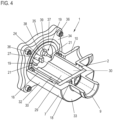
- Fig.1 shows a screw spindle pump 1 according to the invention, with a spindle housing 2, in which in the embodiment shown two spindles are accommodated, namely a drive spindle 3 with a spindle profile and a running spindle 4 with a spindle profile. Both spindle profiles or spindles 3, 4 mesh with each other in a manner known per se.
- This spindle package is driven via the drive spindle 3, which is coupled to a drive motor or its drive shaft (not shown in detail here).
- a coupling element 5 with a plug-in receptacle 6 for a coupling pin of the drive shaft is used for this purpose, the coupling element 5 being coupled to the drive spindle 3 in a rotationally fixed manner.
- the drive motor is placed on or to an outer housing 7 and screwed to it, the quasi hollow cylindrical outer housing 7, as Fig.1 shows, completely accommodates the spindle housing 2.
- the outer housing 7 is closed axially on this side via the drive motor or the motor housing (not shown in detail).
- a cover component 8 is placed axially on the outer housing 7, which closes the outer housing 7 and thus the pump interior on this side.
- the cover component 8, preferably a plastic component, has an axial fluid inlet connection 9, which means that the fluid to be conveyed is sucked in or introduced axially on this suction side. It also has a fluid outlet connection 10 which projects laterally to the side, i.e.
- the seal to the outer housing 7 is also achieved by means of a sealing means (not shown in detail) which is accommodated in a radially open receiving groove 14 formed on the outer housing 7, wherein this receiving groove 14 is radially overlapped by a flange 15 of the cover component 8.
- a complete seal is achieved on the one hand of the outer housing, but also on the other hand of the spindle space, so that the pressurized volume can no longer flow back into the suction area.
- the drive motor mounted on the outer housing 7 has a motor plate which axially closes this side and thus the spindle space on this side, provided it is mounted directly on the outer housing.
- a housing plate can also be interposed, as will be discussed below.
- corresponding sealing elements are also provided on this side.
- a fluid chamber 16 is formed that encompasses the spindle housing 2 by 360°, into which the fluid flowing out of the spindle housing 2 axially, i.e. in the direction of the drive motor, is diverted and enters. This means that the fluid outlet on the spindle housing side communicates with the fluid chamber.
- the fluid chamber 16 in turn communicates with the fluid outlet connection 10, for which purpose a corresponding opening 17 is provided on the cover component 8.
- This opening 17 is open towards the fluid chamber 16.
- the fluid chamber 16 is filled with the fluid which is already under pressure, so that the fluid can exert a corresponding pressure on the spindle housing 2, which counteracts any change in the geometry of the spindle housing 2.
- the deflection takes place via a corresponding deflection cavity, which is either formed on the housing wall of the motor housing which closes the pump chamber, if the latter is placed directly on the outer housing 7, or on the intermediate housing plate which is arranged between the outer housing 7 and the motor housing.
- This housing plate will be described below in more detail below. Figures 4 - 6 described in more detail.
- the two spindles 3, 4 are axially supported on the suction side, i.e. on the cover component 8, where the fluid inlet into the spindle housing 2 is provided, via a support component 18 in the form of a key, so that a defined abutment is formed here.
- the drive spindle 3 is axially supported on the drive shaft of the motor.
- a support device 19 is integrally formed on the plastic spindle housing 2, comprising a web 20 on which an axially projecting support pin 21 projects axially towards the running spindle 4.
- the running spindle 4 can run against this axial support pin 21 with its axial end face 22 or is supported against it.
- the support device 19 is integrally formed on the plastic spindle housing 2 as described. This is therefore a single-material component that not only forms the actual spindle housing, but also includes the support device 19. Since only one running spindle 4 is provided, only one such support device 19 or only one such support pin 21 is to be provided.
- a central ring section 23 is also formed in one piece on the spindle housing 2, which has a bearing bore 24 through which the motor-side drive shaft (not shown in detail) runs and in which it is radially mounted.
- the web 20 extends from this central ring section 24 to the housing wall, and on the other hand, a few further webs 25 are also provided, via which the central ring section 24 is connected to the housing side.
- the bearing bore 24 that accommodates the drive shaft is exactly aligned with the central axis of the spindle bore that accommodates the drive spindle 3, so that there are no tolerances between the drive shaft bearing and the spindle axis and therefore within the coupling of the two components. As a result, there are no imbalances, which means that the spindles run very smoothly and quietly.
- Fig.2 shows a sectional view of the spindle housing 2 together with the drive spindle 3 and the running spindle 4, which clearly mesh with one another.
- the support device 19 which is integrally formed on the spindle housing 2, as indicated by the same hatching. Shown is the web 20 and the axially projecting support pin 21, which projects axially towards the running spindle 4. Also shown is at least one further web 26, via which the ring section 23, in which the bearing bore 24 is formed, is connected to the spindle housing 2.
- the spindle housing 2 is shown again, in this case without the two spindles.
- the two spindle bores are clearly visible, with one spindle bore 29 accommodating the drive spindle 3 and the other spindle bore 30 accommodating the running spindle 4.
- the support pin 21 can be clearly seen on the web 20 shown here. Also shown are further webs 26 and the central ring section 23 with the bearing bore 24.
- the spindle housing 2 has two openings 31 into which the key 18 is inserted and in which it is preferably slightly clamped.
- the two spindles 3, 4 are axially supported on the suction side by the key 18.
- the drive spindle is 3 is axially supported on the drive shaft 27, while the running spindle 4 is supported on the support pin 21.
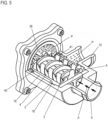
- Fig.4 shows a further embodiment of a screw pump 1 according to the invention, wherein the same reference numerals are used for the same components.
- a spindle housing 2 is also provided, in which three spindles are to be accommodated in the example shown, namely, see Fig.5 , a central drive spindle 3 and two running spindles 4 offset by 180°, which are accommodated in respective spindle bores 29 and 30, but in Fig.4 are not shown in detail.
- an outer housing 7 is also provided, which here is a one-piece pot-like outer housing and which has a cylindrical section 32 which is closed by a housing wall 33.
- the inlet connection 9 is provided on the housing wall 33, which is positioned centrally in axial terms, and on which the outlet connection 10 extending radially to the side is also provided.
- a fluid chamber 16 is provided, which is designed as a circumferential annular pressure chamber between the spindle housing 2 and the outer housing 7, and which here extends almost over the entire length of the spindle housing 2 or the spindle bores 29, 30.
- This fluid chamber 16, which communicates with the outlet connection 10, also communicates with the fluid outlet of the spindle housing 2, so that the pressurized fluid flows into it and the radial pressure is applied to the spindle housing 2.
- the outer housing 7 has a flange 34 on which a housing plate 35 is arranged axially, which is followed by the drive motor (not shown in detail), the arrangement being screwed on using corresponding fastening screws 36.
- the housing plate 35 has an axially extending ring flange 37, with which it engages in the cylindrical opening of the outer housing 7.
- a pot-like recess 38 is formed on the housing plate 35, on the bottom of which a bearing bore 24 is formed, through which the drive shaft 27 passes. Axially from the bottom of the Protruding from the recess 38 are two support devices 19 which run axially to the running spindles 4.
- Each support device 19, which is formed in one piece on the housing plate 35 made of plastic, has a relatively wide, cylindrical base 39, from which a thinner support pin 21 projects axially, on which in turn the respective running spindle 4 can run axially.
- This design is shown in a more detailed, enlarged sectional view in Fig.6 shown. How Fig.6 , but also Fig.5 As can be seen, the recess 38 is designed in a pot-like manner and is rounded at the bottom. This is because the fluid flowing axially out of the fluid outlet of the spindle housing 2 is to be guided radially to the side via this recess 38 and, viewed axially, back into the fluid chamber 16.
- the rounded recess design is useful in that the radial guidance to the outside and the deflection takes place silently because no flow edges and corresponding corners are provided.
- the fluid flow is in Fig.5 shown by the arrows P.
- the inflow occurs via the inlet connection 9.
- the fluid is conveyed axially via the spindle package and exits axially on the pressure side in the direction of the recess 38, which serves as a deflection cavity.
- the recess it is deflected to the side (see the flow arrows P) and can flow back axially, whereby it can flow into the fluid chamber 16 via corresponding openings 40 in a radial flange 41 of the spindle housing 2, which axially delimits the fluid chamber 16. From this it then flows (see the flow arrows P) to the outlet connection 10.
- the key 19 is clamped axially between the front face of the spindle housing 2 and the inner wall of the housing wall 33, whereby an anti-twisting device in the circumferential direction is also provided.
- the key 19 is designed in a cross shape, which makes it possible to arrange the spindle housing 2 and thus the spindle alignment rotated by 90° relative to the outer housing 7 if necessary due to the required spatial positioning of the lateral radial outlet connection 10.
- the aim is to position the spindles 3, 4 as horizontally as possible so that the Spindle axes lie parallel in a horizontal plane, which is advantageous for the most efficient conveying operation possible.
- the support of the running spindles 4 on both sides provided according to the invention, whether in the 2-spindle pump or in the 3-spindle pump, makes it possible to switch the direction of rotation of the spindle if necessary, i.e. to switch from the direction of rotation that conveys the delivery volume from the suction side to the pressure side in the actual conveying operation to the opposite direction of rotation, which may sometimes be necessary in one or the other operating situation. Due to the axial support on both sides, there is no need for axial spindle displacement of the respective running spindle.
- the drive motor can be either a dry runner or a wet runner. If it is a dry runner, the drive shaft 27 (shown here only in stylized form) is housed in a shaft seal ring that is arranged in the bearing bore 24 so that no fluid can flow along the drive shaft 27 and get into the drive motor. The other sealing on this side is carried out as described either via the motor housing wall itself or via the housing plate 35. If it is a wet runner that is to be cooled by the fluid, there is no shaft seal ring around the drive shaft 27 in the bearing bore 24 so that the fluid can flow along it.
Landscapes
- Engineering & Computer Science (AREA)
- Mechanical Engineering (AREA)
- General Engineering & Computer Science (AREA)
- Structures Of Non-Positive Displacement Pumps (AREA)
- Rotary Pumps (AREA)
- Reciprocating Pumps (AREA)
- Electromagnetic Pumps, Or The Like (AREA)
- Details Of Reciprocating Pumps (AREA)
Applications Claiming Priority (1)
| Application Number | Priority Date | Filing Date | Title |
|---|---|---|---|
| DE102021133109.9A DE102021133109A1 (de) | 2021-12-14 | 2021-12-14 | Schraubenspindelpumpe |
Publications (2)
| Publication Number | Publication Date |
|---|---|
| EP4198260A1 EP4198260A1 (de) | 2023-06-21 |
| EP4198260B1 true EP4198260B1 (de) | 2024-07-31 |
Family
ID=84364112
Family Applications (1)
| Application Number | Title | Priority Date | Filing Date |
|---|---|---|---|
| EP22209990.5A Active EP4198260B1 (de) | 2021-12-14 | 2022-11-28 | Schraubenspindelpumpe |
Country Status (7)
| Country | Link |
|---|---|
| US (1) | US11773846B2 (pl) |
| EP (1) | EP4198260B1 (pl) |
| JP (1) | JP7450011B2 (pl) |
| KR (1) | KR102803179B1 (pl) |
| CN (1) | CN116263153A (pl) |
| DE (1) | DE102021133109A1 (pl) |
| PL (1) | PL4198260T3 (pl) |
Cited By (1)
| Publication number | Priority date | Publication date | Assignee | Title |
|---|---|---|---|---|
| EP4124756B1 (en) * | 2021-07-26 | 2025-06-18 | Fluid-O-Tech S.r.l. | Improved screw-spindle pump, particularly for cooling systems |
Family Cites Families (15)
| Publication number | Priority date | Publication date | Assignee | Title |
|---|---|---|---|---|
| GB263540A (en) * | 1925-09-30 | 1926-12-30 | Mavor & Coulson Ltd | Improvements in or connected with rotary engines and the like |
| GB1552385A (en) * | 1975-05-13 | 1979-09-12 | Maekawa Seisakusho Kk | Device for compressing or expanding a gas or for pumping a liquid |
| US4462769A (en) * | 1981-12-02 | 1984-07-31 | Sullair Technology Ab | Method at an oil-injected screw-compressor |
| DE4123384C2 (de) | 1991-07-15 | 1999-08-12 | Leistritz Ag | Kraftstofförderaggregat |
| DE102014102390B3 (de) | 2014-02-25 | 2015-03-26 | Leistritz Pumpen Gmbh | Schraubenspindelpumpe |
| DE102015101443B3 (de) * | 2015-02-02 | 2016-05-12 | Leistritz Pumpen Gmbh | Kraftstoffpumpe |
| JP2017137824A (ja) * | 2016-02-04 | 2017-08-10 | 株式会社Soken | スクリュポンプ |
| DE102017210771B4 (de) * | 2017-06-27 | 2019-05-29 | Continental Automotive Gmbh | Schraubenspindelpumpe, Kraftstoffförderaggregat und Kraftstofffördereinheit |
| DE102017210767B4 (de) | 2017-06-27 | 2019-10-17 | Continental Automotive Gmbh | Schraubenspindelpumpe, Kraftstoffförderaggregat und Kraftstofffördereinheit |
| DE102018130472A1 (de) | 2018-11-30 | 2020-06-04 | Nidec Gpm Gmbh | Schraubenspindelpumpe |
| DE102018131587A1 (de) | 2018-12-10 | 2020-06-10 | Nidec Gpm Gmbh | Regelbare Schraubenspindelpumpe |
| DE102019103470A1 (de) * | 2019-02-12 | 2020-08-13 | Nidec Gpm Gmbh | Elektrische Schraubenspindel-Kühlmittelpumpe |
| DE102019118086A1 (de) * | 2019-07-04 | 2021-01-07 | Nidec Gpm Gmbh | Integrierte Schraubenspindel-Kühlmittelpumpe |
| DE102019132653A1 (de) * | 2019-12-02 | 2021-06-02 | Leistritz Pumpen Gmbh | Schraubenspindelpumpe |
| KR102195349B1 (ko) * | 2019-12-05 | 2020-12-28 | 주식회사 코아비스 | 스크류 펌프 |
-
2021
- 2021-12-14 DE DE102021133109.9A patent/DE102021133109A1/de active Pending
-
2022
- 2022-11-28 EP EP22209990.5A patent/EP4198260B1/de active Active
- 2022-11-28 PL PL22209990.5T patent/PL4198260T3/pl unknown
- 2022-12-07 US US18/076,863 patent/US11773846B2/en active Active
- 2022-12-09 JP JP2022197438A patent/JP7450011B2/ja active Active
- 2022-12-13 CN CN202211593042.1A patent/CN116263153A/zh active Pending
- 2022-12-13 KR KR1020220173579A patent/KR102803179B1/ko active Active
Cited By (1)
| Publication number | Priority date | Publication date | Assignee | Title |
|---|---|---|---|---|
| EP4124756B1 (en) * | 2021-07-26 | 2025-06-18 | Fluid-O-Tech S.r.l. | Improved screw-spindle pump, particularly for cooling systems |
Also Published As
| Publication number | Publication date |
|---|---|
| PL4198260T3 (pl) | 2024-12-16 |
| EP4198260A1 (de) | 2023-06-21 |
| JP7450011B2 (ja) | 2024-03-14 |
| JP2023088300A (ja) | 2023-06-26 |
| KR102803179B1 (ko) | 2025-05-08 |
| DE102021133109A1 (de) | 2023-06-15 |
| US11773846B2 (en) | 2023-10-03 |
| US20230184244A1 (en) | 2023-06-15 |
| CN116263153A (zh) | 2023-06-16 |
| KR20230091043A (ko) | 2023-06-22 |
Similar Documents
| Publication | Publication Date | Title |
|---|---|---|
| EP2087258B1 (de) | Elektromotorischer linearantrieb | |
| EP2732165B1 (de) | Schraubenverdichter | |
| EP2626567B2 (de) | Pumpengehäuse | |
| EP4198260B1 (de) | Schraubenspindelpumpe | |
| EP2828527A1 (de) | Kältemittelverdichter | |
| DE102009019721B4 (de) | Hydraulisches System | |
| DE69326495T2 (de) | Kraftstoffpumpe | |
| EP3234369B1 (de) | Axialventilator | |
| EP4198311B1 (de) | Schraubenspindelpumpe | |
| EP2322803B1 (de) | Pumpe mit einer magnetkupplung | |
| DE102010051316A1 (de) | Vakuumpumpe | |
| DE102016225923A1 (de) | Pumpenaggregat für ein Hydrauliksystem und Kanalelement für ein Pumpenaggregat | |
| EP4198309B1 (de) | Schraubenspindelpumpe | |
| EP4198261B1 (de) | Schraubenspindelpumpe | |
| DE102004034925B3 (de) | Einflügelvakuumpumpe | |
| WO2002081913A2 (de) | Hydraulisches pumpenaggregat | |
| DE10003644C1 (de) | Kreiselpumpe | |
| DE102021208481A1 (de) | Förderpumpe und Kraftfahrzeug mit einer derartigen Förderpumpe | |
| DE4304334A1 (de) | Aggregat zum Fördern von Kraftstoff aus einem Vorratstank zur Brennkraftmaschine eines Kraftfahrzeugs | |
| EP4198310B1 (de) | Schraubenspindelpumpe | |
| EP4217610B1 (de) | Motor-pumpe-einheit | |
| DE4107720C2 (de) | Flügelzellenpumpe | |
| WO2009019101A1 (de) | Verdrängerpumpe | |
| DE102016015919B4 (de) | Pumpenaggregat für ein Hydrauliksystem und Kanalelement für ein Pumpenaggregat | |
| WO2007028429A1 (de) | Zahnradpumpe |
Legal Events
| Date | Code | Title | Description |
|---|---|---|---|
| PUAI | Public reference made under article 153(3) epc to a published international application that has entered the european phase |
Free format text: ORIGINAL CODE: 0009012 |
|
| STAA | Information on the status of an ep patent application or granted ep patent |
Free format text: STATUS: THE APPLICATION HAS BEEN PUBLISHED |
|
| AK | Designated contracting states |
Kind code of ref document: A1 Designated state(s): AL AT BE BG CH CY CZ DE DK EE ES FI FR GB GR HR HU IE IS IT LI LT LU LV MC ME MK MT NL NO PL PT RO RS SE SI SK SM TR |
|
| P01 | Opt-out of the competence of the unified patent court (upc) registered |
Effective date: 20230921 |
|
| STAA | Information on the status of an ep patent application or granted ep patent |
Free format text: STATUS: REQUEST FOR EXAMINATION WAS MADE |
|
| 17P | Request for examination filed |
Effective date: 20231030 |
|
| RBV | Designated contracting states (corrected) |
Designated state(s): AL AT BE BG CH CY CZ DE DK EE ES FI FR GB GR HR HU IE IS IT LI LT LU LV MC ME MK MT NL NO PL PT RO RS SE SI SK SM TR |
|
| GRAP | Despatch of communication of intention to grant a patent |
Free format text: ORIGINAL CODE: EPIDOSNIGR1 |
|
| STAA | Information on the status of an ep patent application or granted ep patent |
Free format text: STATUS: GRANT OF PATENT IS INTENDED |
|
| INTG | Intention to grant announced |
Effective date: 20240419 |
|
| RAP3 | Party data changed (applicant data changed or rights of an application transferred) |
Owner name: LEISTRITZ PUMPEN GMBH |
|
| GRAS | Grant fee paid |
Free format text: ORIGINAL CODE: EPIDOSNIGR3 |
|
| GRAA | (expected) grant |
Free format text: ORIGINAL CODE: 0009210 |
|
| STAA | Information on the status of an ep patent application or granted ep patent |
Free format text: STATUS: THE PATENT HAS BEEN GRANTED |
|
| AK | Designated contracting states |
Kind code of ref document: B1 Designated state(s): AL AT BE BG CH CY CZ DE DK EE ES FI FR GB GR HR HU IE IS IT LI LT LU LV MC ME MK MT NL NO PL PT RO RS SE SI SK SM TR |
|
| REG | Reference to a national code |
Ref country code: CH Ref legal event code: EP Ref country code: GB Ref legal event code: FG4D Free format text: NOT ENGLISH |
|
| REG | Reference to a national code |
Ref country code: DE Ref legal event code: R096 Ref document number: 502022001357 Country of ref document: DE |
|
| REG | Reference to a national code |
Ref country code: IE Ref legal event code: FG4D Free format text: LANGUAGE OF EP DOCUMENT: GERMAN |
|
| REG | Reference to a national code |
Ref country code: LT Ref legal event code: MG9D |
|
| REG | Reference to a national code |
Ref country code: NL Ref legal event code: MP Effective date: 20240731 |
|
| PG25 | Lapsed in a contracting state [announced via postgrant information from national office to epo] |
Ref country code: PT Free format text: LAPSE BECAUSE OF FAILURE TO SUBMIT A TRANSLATION OF THE DESCRIPTION OR TO PAY THE FEE WITHIN THE PRESCRIBED TIME-LIMIT Effective date: 20241202 |
|
| PG25 | Lapsed in a contracting state [announced via postgrant information from national office to epo] |
Ref country code: PT Free format text: LAPSE BECAUSE OF FAILURE TO SUBMIT A TRANSLATION OF THE DESCRIPTION OR TO PAY THE FEE WITHIN THE PRESCRIBED TIME-LIMIT Effective date: 20241202 |
|
| PGFP | Annual fee paid to national office [announced via postgrant information from national office to epo] |
Ref country code: DE Payment date: 20241113 Year of fee payment: 3 |
|
| PG25 | Lapsed in a contracting state [announced via postgrant information from national office to epo] |
Ref country code: NO Free format text: LAPSE BECAUSE OF FAILURE TO SUBMIT A TRANSLATION OF THE DESCRIPTION OR TO PAY THE FEE WITHIN THE PRESCRIBED TIME-LIMIT Effective date: 20241031 |
|
| PG25 | Lapsed in a contracting state [announced via postgrant information from national office to epo] |
Ref country code: GR Free format text: LAPSE BECAUSE OF FAILURE TO SUBMIT A TRANSLATION OF THE DESCRIPTION OR TO PAY THE FEE WITHIN THE PRESCRIBED TIME-LIMIT Effective date: 20241101 Ref country code: NL Free format text: LAPSE BECAUSE OF FAILURE TO SUBMIT A TRANSLATION OF THE DESCRIPTION OR TO PAY THE FEE WITHIN THE PRESCRIBED TIME-LIMIT Effective date: 20240731 Ref country code: FI Free format text: LAPSE BECAUSE OF FAILURE TO SUBMIT A TRANSLATION OF THE DESCRIPTION OR TO PAY THE FEE WITHIN THE PRESCRIBED TIME-LIMIT Effective date: 20240731 |
|
| PGFP | Annual fee paid to national office [announced via postgrant information from national office to epo] |
Ref country code: PL Payment date: 20241118 Year of fee payment: 3 |
|
| PG25 | Lapsed in a contracting state [announced via postgrant information from national office to epo] |
Ref country code: BG Free format text: LAPSE BECAUSE OF FAILURE TO SUBMIT A TRANSLATION OF THE DESCRIPTION OR TO PAY THE FEE WITHIN THE PRESCRIBED TIME-LIMIT Effective date: 20240731 |
|
| PGFP | Annual fee paid to national office [announced via postgrant information from national office to epo] |
Ref country code: FR Payment date: 20241128 Year of fee payment: 3 |
|
| PG25 | Lapsed in a contracting state [announced via postgrant information from national office to epo] |
Ref country code: LV Free format text: LAPSE BECAUSE OF FAILURE TO SUBMIT A TRANSLATION OF THE DESCRIPTION OR TO PAY THE FEE WITHIN THE PRESCRIBED TIME-LIMIT Effective date: 20240731 |
|
| PG25 | Lapsed in a contracting state [announced via postgrant information from national office to epo] |
Ref country code: IS Free format text: LAPSE BECAUSE OF FAILURE TO SUBMIT A TRANSLATION OF THE DESCRIPTION OR TO PAY THE FEE WITHIN THE PRESCRIBED TIME-LIMIT Effective date: 20241130 |
|
| PG25 | Lapsed in a contracting state [announced via postgrant information from national office to epo] |
Ref country code: HR Free format text: LAPSE BECAUSE OF FAILURE TO SUBMIT A TRANSLATION OF THE DESCRIPTION OR TO PAY THE FEE WITHIN THE PRESCRIBED TIME-LIMIT Effective date: 20240731 |
|
| PGFP | Annual fee paid to national office [announced via postgrant information from national office to epo] |
Ref country code: RO Payment date: 20241126 Year of fee payment: 3 |
|
| PG25 | Lapsed in a contracting state [announced via postgrant information from national office to epo] |
Ref country code: RS Free format text: LAPSE BECAUSE OF FAILURE TO SUBMIT A TRANSLATION OF THE DESCRIPTION OR TO PAY THE FEE WITHIN THE PRESCRIBED TIME-LIMIT Effective date: 20241031 Ref country code: ES Free format text: LAPSE BECAUSE OF FAILURE TO SUBMIT A TRANSLATION OF THE DESCRIPTION OR TO PAY THE FEE WITHIN THE PRESCRIBED TIME-LIMIT Effective date: 20240731 |
|
| PGFP | Annual fee paid to national office [announced via postgrant information from national office to epo] |
Ref country code: IT Payment date: 20241130 Year of fee payment: 3 |
|
| PG25 | Lapsed in a contracting state [announced via postgrant information from national office to epo] |
Ref country code: RS Free format text: LAPSE BECAUSE OF FAILURE TO SUBMIT A TRANSLATION OF THE DESCRIPTION OR TO PAY THE FEE WITHIN THE PRESCRIBED TIME-LIMIT Effective date: 20241031 Ref country code: NO Free format text: LAPSE BECAUSE OF FAILURE TO SUBMIT A TRANSLATION OF THE DESCRIPTION OR TO PAY THE FEE WITHIN THE PRESCRIBED TIME-LIMIT Effective date: 20241031 Ref country code: NL Free format text: LAPSE BECAUSE OF FAILURE TO SUBMIT A TRANSLATION OF THE DESCRIPTION OR TO PAY THE FEE WITHIN THE PRESCRIBED TIME-LIMIT Effective date: 20240731 Ref country code: LV Free format text: LAPSE BECAUSE OF FAILURE TO SUBMIT A TRANSLATION OF THE DESCRIPTION OR TO PAY THE FEE WITHIN THE PRESCRIBED TIME-LIMIT Effective date: 20240731 Ref country code: IS Free format text: LAPSE BECAUSE OF FAILURE TO SUBMIT A TRANSLATION OF THE DESCRIPTION OR TO PAY THE FEE WITHIN THE PRESCRIBED TIME-LIMIT Effective date: 20241130 Ref country code: HR Free format text: LAPSE BECAUSE OF FAILURE TO SUBMIT A TRANSLATION OF THE DESCRIPTION OR TO PAY THE FEE WITHIN THE PRESCRIBED TIME-LIMIT Effective date: 20240731 Ref country code: GR Free format text: LAPSE BECAUSE OF FAILURE TO SUBMIT A TRANSLATION OF THE DESCRIPTION OR TO PAY THE FEE WITHIN THE PRESCRIBED TIME-LIMIT Effective date: 20241101 Ref country code: FI Free format text: LAPSE BECAUSE OF FAILURE TO SUBMIT A TRANSLATION OF THE DESCRIPTION OR TO PAY THE FEE WITHIN THE PRESCRIBED TIME-LIMIT Effective date: 20240731 Ref country code: ES Free format text: LAPSE BECAUSE OF FAILURE TO SUBMIT A TRANSLATION OF THE DESCRIPTION OR TO PAY THE FEE WITHIN THE PRESCRIBED TIME-LIMIT Effective date: 20240731 Ref country code: BG Free format text: LAPSE BECAUSE OF FAILURE TO SUBMIT A TRANSLATION OF THE DESCRIPTION OR TO PAY THE FEE WITHIN THE PRESCRIBED TIME-LIMIT Effective date: 20240731 |
|
| PG25 | Lapsed in a contracting state [announced via postgrant information from national office to epo] |
Ref country code: SM Free format text: LAPSE BECAUSE OF FAILURE TO SUBMIT A TRANSLATION OF THE DESCRIPTION OR TO PAY THE FEE WITHIN THE PRESCRIBED TIME-LIMIT Effective date: 20240731 Ref country code: DK Free format text: LAPSE BECAUSE OF FAILURE TO SUBMIT A TRANSLATION OF THE DESCRIPTION OR TO PAY THE FEE WITHIN THE PRESCRIBED TIME-LIMIT Effective date: 20240731 |
|
| PG25 | Lapsed in a contracting state [announced via postgrant information from national office to epo] |
Ref country code: EE Free format text: LAPSE BECAUSE OF FAILURE TO SUBMIT A TRANSLATION OF THE DESCRIPTION OR TO PAY THE FEE WITHIN THE PRESCRIBED TIME-LIMIT Effective date: 20240731 |
|
| PG25 | Lapsed in a contracting state [announced via postgrant information from national office to epo] |
Ref country code: CZ Free format text: LAPSE BECAUSE OF FAILURE TO SUBMIT A TRANSLATION OF THE DESCRIPTION OR TO PAY THE FEE WITHIN THE PRESCRIBED TIME-LIMIT Effective date: 20240731 |
|
| PG25 | Lapsed in a contracting state [announced via postgrant information from national office to epo] |
Ref country code: SK Free format text: LAPSE BECAUSE OF FAILURE TO SUBMIT A TRANSLATION OF THE DESCRIPTION OR TO PAY THE FEE WITHIN THE PRESCRIBED TIME-LIMIT Effective date: 20240731 |
|
| REG | Reference to a national code |
Ref country code: DE Ref legal event code: R097 Ref document number: 502022001357 Country of ref document: DE |
|
| PLBE | No opposition filed within time limit |
Free format text: ORIGINAL CODE: 0009261 |
|
| STAA | Information on the status of an ep patent application or granted ep patent |
Free format text: STATUS: NO OPPOSITION FILED WITHIN TIME LIMIT |
|
| PG25 | Lapsed in a contracting state [announced via postgrant information from national office to epo] |
Ref country code: MC Free format text: LAPSE BECAUSE OF FAILURE TO SUBMIT A TRANSLATION OF THE DESCRIPTION OR TO PAY THE FEE WITHIN THE PRESCRIBED TIME-LIMIT Effective date: 20240731 |
|
| 26N | No opposition filed |
Effective date: 20250501 |
|
| PG25 | Lapsed in a contracting state [announced via postgrant information from national office to epo] |
Ref country code: LU Free format text: LAPSE BECAUSE OF NON-PAYMENT OF DUE FEES Effective date: 20241128 |
|
| REG | Reference to a national code |
Ref country code: BE Ref legal event code: MM Effective date: 20241130 |
|
| PG25 | Lapsed in a contracting state [announced via postgrant information from national office to epo] |
Ref country code: SE Free format text: LAPSE BECAUSE OF FAILURE TO SUBMIT A TRANSLATION OF THE DESCRIPTION OR TO PAY THE FEE WITHIN THE PRESCRIBED TIME-LIMIT Effective date: 20240731 |
|
| PG25 | Lapsed in a contracting state [announced via postgrant information from national office to epo] |
Ref country code: BE Free format text: LAPSE BECAUSE OF NON-PAYMENT OF DUE FEES Effective date: 20241130 |
|
| PG25 | Lapsed in a contracting state [announced via postgrant information from national office to epo] |
Ref country code: IE Free format text: LAPSE BECAUSE OF NON-PAYMENT OF DUE FEES Effective date: 20241128 |
|
| REG | Reference to a national code |
Ref country code: CH Ref legal event code: U11 Free format text: ST27 STATUS EVENT CODE: U-0-0-U10-U11 (AS PROVIDED BY THE NATIONAL OFFICE) Effective date: 20251201 |