EP4198243B1 - Rahmenprofilanordnung - Google Patents
Rahmenprofilanordnung Download PDFInfo
- Publication number
- EP4198243B1 EP4198243B1 EP22212733.4A EP22212733A EP4198243B1 EP 4198243 B1 EP4198243 B1 EP 4198243B1 EP 22212733 A EP22212733 A EP 22212733A EP 4198243 B1 EP4198243 B1 EP 4198243B1
- Authority
- EP
- European Patent Office
- Prior art keywords
- profile
- frame
- carrier
- fastened
- arrangement according
- Prior art date
- Legal status (The legal status is an assumption and is not a legal conclusion. Google has not performed a legal analysis and makes no representation as to the accuracy of the status listed.)
- Active
Links
Images


Classifications
-
- E—FIXED CONSTRUCTIONS
- E06—DOORS, WINDOWS, SHUTTERS, OR ROLLER BLINDS IN GENERAL; LADDERS
- E06B—FIXED OR MOVABLE CLOSURES FOR OPENINGS IN BUILDINGS, VEHICLES, FENCES OR LIKE ENCLOSURES IN GENERAL, e.g. DOORS, WINDOWS, BLINDS, GATES
- E06B3/00—Window sashes, door leaves, or like elements for closing wall or like openings; Layout of fixed or moving closures, e.g. windows in wall or like openings; Features of rigidly-mounted outer frames relating to the mounting of wing frames
- E06B3/54—Fixing of glass panes or like plates
- E06B3/58—Fixing of glass panes or like plates by means of borders, cleats, or the like
- E06B3/585—Fixing of glass panes or like plates by means of borders, cleats, or the like adjustable, e.g. for accommodating panes of various thickness, or with provisions for altering the clamping force on the pane
-
- E—FIXED CONSTRUCTIONS
- E06—DOORS, WINDOWS, SHUTTERS, OR ROLLER BLINDS IN GENERAL; LADDERS
- E06B—FIXED OR MOVABLE CLOSURES FOR OPENINGS IN BUILDINGS, VEHICLES, FENCES OR LIKE ENCLOSURES IN GENERAL, e.g. DOORS, WINDOWS, BLINDS, GATES
- E06B3/00—Window sashes, door leaves, or like elements for closing wall or like openings; Layout of fixed or moving closures, e.g. windows in wall or like openings; Features of rigidly-mounted outer frames relating to the mounting of wing frames
- E06B3/30—Coverings, e.g. protecting against weather, for decorative purposes
- E06B3/301—Coverings, e.g. protecting against weather, for decorative purposes consisting of prefabricated profiled members or glass
- E06B3/306—Covering plastic frames with metal or plastic profiled members
Definitions
- the invention relates to a frame profile arrangement for window or door frames, with a frame profile and a glazing bead that can be clamped to it.
- the invention also relates to a glazing bead for a frame profile arrangement and a frame that is composed of several frame profile arrangements.
- Such arrangements are generally known in the art, e.g. from DE-OS 2 012 353 .
- the glazing bead is used to attach a glass element between the frame profiles and the glazing bead after a frame has been made from several such frame profile arrangements.
- This type of structure is used regardless of the material of the frame profile arrangement, i.e. both for plastic windows and doors and for those made of aluminum.
- a classic aluminum frame system also includes an aluminum glazing bead that forms the transition between the sash frame profile or, in the case of fixed glazing, between the frame profile and the glazing.
- glazing beads are arranged on the side facing the room.
- the glass element can be easily inserted from the room, and the glass element is also easily accessible in the event of repairs.
- glazing beads are installed/inserted/mounted towards the inside of the building as standard.
- the glazing bead can be snapped into the frame profile and fixes the glass element in the frame or its frame profiles.
- the respective glazing bead is part of the cross or longitudinal beam.
- the glazing bead forms a surrounding frame and presses the glass pane to a stop in the frame profile and thus locks the glass in the correct place within the glass rebate. There is a seal between the glass strip and the glass pane, the so-called glazing seal.
- Window frames and door frames are widely made from hollow plastic profiles with glazing beads, also made from plastic, which are mitred at the end. Since the plastic glazing beads have a certain elasticity and are flexible, they can be fitted precisely by bending them. The two short sides are first snapped into place, the two long glazing beads are slightly bent before being inserted and positioned in the corners of the sash frame and hammered into the groove of the sash or frame profile with a soft-face hammer. In order to achieve the best possible seal in the corner areas of the glazing bead profiles that meet one another, the glazing bead profiles can be given an oversize.
- a seal to the glass does not need to be added in a further step if it can be extruded during the extrusion process of glazing bead profile production. Otherwise, it is mounted on the glazing bead after production.
- glazing beads are particularly important. They ensure a smooth and routine assembly process.
- a primary goal is to apply the proven advantages of a tried and tested frame processing method with plastic frame profiles, also for frames, e.g. for windows or doors, with an aluminum look.
- Aluminium profiles are rigid and not bendable, which is why the conventional glazing bead assembly with bending at mitre cuts is not applicable here. Due to the material properties of aluminium, a glazing bead can be in the corner area, only make a straight cut into the sash or frame profile. The glazing beads are joined together to form a frame parallel to the glass element on the sash or frame profile and meet butt-jointed in the corners.
- the glazing seal can only be inserted after the glazing beads have been installed, between the glazing beads and the glass element. This step must always be carried out by hand and cannot be automated. The current processing of glazing beads by aluminum system providers is therefore laborious. Easier and faster processing is required.
- a subsequently installed wedge seal has a very large gap for technical reasons, which represents the visible width of the seal of approx. 12 mm, which is also undesirable and has a negative impact on the external appearance.
- the object of the invention is therefore to combine the advantages of elastic PVC with the corrosion-resistant and optical properties of aluminum and to provide a frame profile arrangement with a glazing bead that enables rapid glazing by bending and preferably allows the use of extruded, extruded or rolled-in seals, since the seal in the glazing bead can be introduced automatically and the gap size, in particular of e.g. approx. 3-5 mm, is significantly smaller.
- glazing beads made of plastic can be equipped with seals during production and the subsequent insertion of a wedge seal between the glass element and the glazing bead is not necessary.
- a glazing bead which comprises a plastic carrier profile that can be clamped to the frame profile and an aluminium cover, is made of DE202019107047U and out FR2904354A known.
- the invention can therefore exploit the advantages of mounting a classic plastic glazing bead with the plastic support profile and then exploit the advantages provided by aluminum as a material with the aluminum cover.
- the carrier profile fulfils the function of a conventional glazing bead.
- This is characterised by a fully-fledged plastic profile, preferably one that, when viewed in cross-section, has a closed plastic cover on all outer sides that encloses hollow spaces on the inside.
- the carrier profile is preferably connected to the frame profile via a clip connection or at least can be connected. To do this, the clip foot is positioned on the receiving groove of the frame profile and clipped in securely.
- the carrier profile has at least one sealing lip. This can preferably be extruded onto the carrier profile, extruded in or inserted, in particular rolled in.
- the carrier profile preferably has a receiving groove to accommodate this so-called glazing seal. This can already have been extruded in during the extrusion process or it can be rolled in with the help of a machine or inserted manually afterwards.
- a preferred variant provides that at least one sealing lip is extruded during the extrusion process. It should be emphasized that the possibility of extruding or extruding sealing materials such as EPDM is only possible on plastic material.
- the aluminum cover has at least one locking lug or positioning lug, with which the aluminum cover is held in a locking or at least positioning manner in a receiving groove of the carrier profile.
- the locking lug or positioning lug can further preferably be shaped complementarily to the receiving groove.
- the aluminum cover has two locking lugs or positioning lugs, each of which is assigned a receiving groove on the support profile.
- the receiving groove serves as a fastening means and/or positioning for the aluminum cover, which forms the outer cover of the visible surface of the carrier profile.
- the aluminum cover forms a clamp connection with the plastic support profile when clicked onto it and gives the frame profile with glazing bead a uniform external appearance with an aluminum look.
- the aluminum cover preferably has two locking lugs, which are formed by projections that can be locked into the carrier profile and are preferably shaped to complement the receiving grooves in the carrier profile for a locking connection.
- the locking lug can be designed in the shape of a hook, for example, but can optionally also be designed as knobs or beads that lock into corresponding recesses, undercuts or cutouts in the carrier profile after assembly.
- a snap-in connection is a type of connection that is extremely suitable for the material and easy to assemble and disassemble.
- the aluminum cover is placed parallel to the support profile like a cap and pressed into place. When the aluminum cover is clicked onto the support profile, a locking connection is created between the two profiles.
- an aluminum cover is conceivable that is provided with a locking lug or at least with a positioning lug and is additionally glued to the support profile.
- the locking lug or positioning lug is used during assembly to position the aluminum cover, which is then pivoted onto the support profile and glued.
- the aluminum cover can therefore be connected to the support profile only by locking, only by adhesive (in particular positioned with a positioning lug) or by a combination of locking and adhesive.
- the aluminum cover When viewed in cross-section, the aluminum cover preferably has two arms, each with a free end, preferably which are prestressed towards one another, in particular thereby giving the locking connection a tight fit.
- the angle between the arms with the free end can be 90 degrees. It can also be provided that the angle is less than 90 degrees, in particular 87 to 89.9 degrees, in order to achieve prestress.
- the arms with the free ends can be connected directly to one another.
- the aluminum cover has two arms with free ends that are connected by a connecting arm, wherein each arm with a free end encloses an angle of greater than 90 degrees with the connecting arm, in particular an angle of 125 to 145 degrees.
- the aluminum cover can be snapped/clicked onto the plastic support profile without tools and can preferably be dismantled just as easily.
- the PVC support profiles which fulfill the function of the glazing beads, are first joined to the frame profile and assembled in the usual way.
- the aluminum covers are then placed, in particular snapped, onto the support profiles to ensure a uniform external appearance.
- the glazing bead frame When assembled, the glazing bead frame according to the invention comprises a concealed frame of PVC support profiles and a visually visible frame consisting of aluminum covers.
- the aluminum covers can be cut straight or mitred in the corners.
- the support profiles are preferably mitred like conventional glazing beads.
- the aluminum cover can be attached to the carrier profile by additional, point-by-point or surface bonding, e.g. using adhesives or double-sided adhesive tape.
- suitable adhesives ensures that the aluminum cover can be removed without leaving any residue if the aluminum cover or the carrier profile is replaced.
- the aluminum cover can be designed in different geometries. It can be provided that the aluminum cover is arranged in the assembled state, in particular in the visible area, in contact with the carrier profile and/or partially spaced from it. In particular, at least one cavity can be enclosed between the carrier profile and the aluminum cover, in particular if the carrier profile has a bevel on the outer visible side that is covered by the aluminum cover. It is preferably provided that the aluminum cover completely covers the visible area of the carrier profile from the glazing seal of the carrier profile to the frame profile, in particular adjoins the glazing seal without gaps.
- the wall thickness of the webs forming the outer wall of the carrier profile is smaller than the wall thickness of the webs of the carrier profile pointing towards the glass rebate of the frame profile and/or than the wall thickness of the webs of the carrier profile not in contact with the aluminum cover.
- the width of the glazing beads must be adjusted.
- the preferred method for this is to use a universally applicable support profile.
- the invention provides that the carrier profile is formed by a base profile and an attachment profile attached/attachable to it.
- the carrier profile is thus formed in two parts.
- the base profile and attachment profile can preferably also be detached from each other again after attachment.
- the attachment profile has the glazing seal in the form of at least one sealing lip.
- connection between the base profile and the attachment profile is preferably formed in a leg of the carrier profile, which, or its lower surface, lies parallel to the glazing rebate surface of the frame profile when installed.
- the invention preferably provides for the length of this leg of the support profile to be variable.
- At least one of the profiles of the base profile and the attachment profile can be shortened.
- the shortening is preferably implemented in such a way that even after shortening, the respective profile has a fastening area for the other profile.
- the base profile is particularly preferably designed to be shortenable, in particular on the side facing the glazing seal.
- the shortenable profile in particular the base profile, can be designed to be open in the direction of the other profile, in particular the attachment profile.
- a recess is formed at these open ends, to or in which the other profile, in particular the attachment profile, can be or is attached.
- the open recess on the shortenable profile is preferably surrounded by recess walls and at least one recess wall has a fastening structure pointing into the interior of the recess, to which the other profile can be fastened, in particular with a corresponding fastening element.
- At least one recess wall preferably two opposite recess walls, have several, preferably equidistant, locking grooves.
- Each locking groove preferably runs parallel to the opening plane of the open recess. Different locking grooves on the same recess wall have different distances from the opening plane.
- the profile that can be fastened to the shortenable profile e.g. the base profile, e.g. the attachment profile, preferably has a fastening area that can be inserted into the open recess, e.g. with a collar as a corresponding fastening element that engages in at least one locking groove of a recess wall.
- the carrier profile can be shortened to suit the glass thickness by cutting, sawing or milling one of the two profiles of the base profile or attachment profile from which the carrier profile is formed, in particular by reducing the depth of the open recess.
- the open profile side of the cut profile, in particular the base profile, is closed with the other profile, in particular the attachment profile, preferably made of TPE.
- thermoplastic elastomers combine the efficient processing properties of thermoplastics with the softness and flexibility of elastomers and fulfill the function of a plug that closes the open profile.
- the attachment profile has the collar located in the open recess, which is inserted into the inner profile formed by the locking grooves of the base profile, so that a firm locking connection is created between the attachment profile and the base profile.
- the attachment profile and the preferably open base profile together form a support profile that is covered with the aluminum cover.
- the aluminium cover When installed, the aluminium cover preferably connects seamlessly to the glazing seal and to the frame profile, in particular to an aluminium cover that is also located on the frame profile.
- the glazing bead according to the invention offers a significant advantage for the isothermal curve due to its "substructure" of the plastic support profile. Since plastic has a lower thermal conductivity than aluminum, thermal insulation is supported and the isothermal curve is optimized in the critical transition area between the glazing bead and the glazing.
- Figure 1 is a cross-section through a sash and a frame profile 10, 20 with the glazing bead 25 with extruded sealing lips 40.
- a frame group consisting of a sash frame and a frame profile 10, 20 is shown in the closed position.
- This is a system in which the sash frame and frame profile 10, 20 essentially has a core made of plastic and is covered with aluminum shells 20 ⁇ , 20" on the visible surfaces on the weather and room sides.
- the two-part glazing bead 25 is composed of the carrier profile 30 and an aluminum cover 30'.
- the carrier profile 30 is made of a hollow plastic profile.
- the carrier profile 30 takes over the function of the glass strip known to date in the state of the art and clamps the glass element (not shown) between the sash overlap 23 and the support profile 30.
- the support profile 30 is elastically clipped with its clip foot 31 in the receiving groove 32 of the sash frame profile 20.
- the contact pressure positions the glass element centrally between the sash overlap 23 and the support profile 30 and clamps it in the area of the glass rebate.
- the Figure 1 shows a seal extruded onto the carrier profile 30 during the extrusion process.
- Two sealing lips 40 of the seal are arranged between the glass element and the sash frame profile 20 and when the carrier profile 30 is fitted, the sealing lips 40 are pressed together to form a gap of, for example, approx. 3-5 mm to the glass element. Only one sealing lip 40 can also be provided. The appearance of a narrow sealing gap is desired.
- the PVC carrier profile 30 is covered with an aluminum cover 30'.
- Figure 2 shows a detailed view of Figure 1 in cross-section through the two-part glass strip 25 with extruded sealing lips 40.
- the aluminum cover 30' can be snapped/clicked onto the plastic support profile 30 without tools and can be removed just as easily. It serves to enhance the appearance and has no static holding function for the glass element.
- the aluminum cover 30' has two arms with free ends 35, 36, which are pre-tensioned towards each other and give the locking connection a tight fit.
- the arms of the aluminum cover with the free ends 35, 36 are connected directly to each other and can form an angle of 90 degrees between them or, to create a pre-tension, an angle that is slightly smaller than 90 degrees, e.g. 87 to 89.9 degrees.
- the aluminium cover 30 ⁇ which preferably corresponds in length to the length of the support profile 30, is fixed with the locking lugs shown in the cross section 33, which form continuous projections in their longitudinal extension, are clicked into the preferably complementarily shaped receiving grooves 32, which in turn form grooves extending in the longitudinal direction.
- the receiving grooves 32 can preferably be provided with undercuts so that the respective locking lug 33 can engage behind them.
- adhesive can be used as an additional connecting means, which is applied between the support profile 30 and the aluminum cover 30' in a point-by-point or planar manner, in particular on the surface of one or each of the two arms with the free ends 35, 36.
- the two-part glazing bead 25 is preferably characterized in that the wall thickness of the webs of the carrier profile 30 facing the outer visible side in the contact area with the aluminum cover 30' is smaller than the wall thickness of the webs of the carrier profile 30 facing the inside or the glass rebate surface in the area not contacted by the aluminum cover.
- the webs or outer walls 37 of the carrier profile 30 oriented towards the visible area can have a material-saving, smaller wall thickness than the inner webs/inner walls.
- the aluminum cover 30' completely covers the visible area from the glazing seal 40 to the frame profile 10/20 (sash or frame profile) or its aluminum cover.
- the geometry of the aluminum cover 30' can preferably correspond to the geometry of the visible surface of the carrier profile 30.
- Figure 3 represents a cross-section through a sash frame and a frame profile 20, 10 with the glazing bead 25 with rolled or hand-drawn seal 40.
- the type of seal 40 is the only difference in this embodiment to the frame assembly in Figure 1 .
- the carrier profile 30 has a seal receiving groove 41 to accommodate a so-called glazing seal 40.
- a so-called glazing seal 40 An example of a rolled-in seal 40 is shown. This may have already been rolled in with the aid of a machine during the extrusion process.
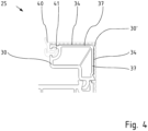
- Figure 4 shows the detailed view of Figure 3 in cross section through the glazing bead 25 with rolled or hand-drawn seal 40.
- the carrier profile 30 here forms the part of the glazing bead 25 with holding and clamping function and the aluminum cover 30' surrounds the outer surfaces 37 of the carrier profile 30 in the visible area.
- the outer wall thickness of the walls/webs 37 of the carrier profile 30 is also smaller than the webs in the non-contact area or those facing the glass rebate surface.
- the aluminum cover 30' adjoins the seal 40 and the sash frame profile 20 / or, in the case of fixed glazing, the frame profile 10 without any gaps.
- Figure 5 shows a detailed view in cross section through the glazing bead 25 in a further embodiment of the carrier profile 30 with rolled-in or hand-drawn seal 40'.
- This embodiment can also be provided with an extruded seal 40.
- This variant differs in a different embodiment of the carrier profile 30.
- the outer wall 37 is provided with a bevel on the room side.
- the same aluminum cover 30 as for the Figures 1 to 4 described, can be used despite varying shapes of the carrier profile 30.
- the aluminum cover 30' can contact the carrier profile 30 in the visible area in sections and can be arranged at a distance in sections, in particular in the overlap area of the bevel, and thereby enclose at least one cavity 42 between itself and the support profile 30.
- Figure 6 shows a detailed view in cross section through the glass strip 25 in a further embodiment of the aluminum cover 30' with rolled or hand-drawn seal 40, which is also possible with extruded seal 40.
- the support profile 30 is arranged in the visible area in complete contact with the aluminum cover 30'.
- the aluminum cover 30' has two arms with free ends that are indirectly connected via a connecting arm, wherein the angles between an arm with a free end and the connecting arm are greater than 90 degrees and the arms with the free ends are at least substantially at 90 degrees to one another or at an angle of less than 90 degrees, in particular 87 to 89.9 degrees.
- the outer shape of the carrier element 30 and the inner shape of the aluminum cover 30' are preferably congruent.
- Figure 7a shows a detailed view in cross section through the glazing bead 25 according to the invention in a further embodiment in which the carrier profile 30 is formed from a base profile 30a and an attachment profile 50.
- the attachment profile 50 has a seal 40 extruded onto it or, as shown here, inserted into the sealing groove 41.
- the base profile 30a is an open profile which, in terms of the cross section, can be shortened on the side facing the seal 40.
- the open profile side is closed with the attachment profile 50, preferably made of TPE.
- Thermoplastic elastomers (TPE) combine the efficient processing properties of thermoplastics with the softness and flexibility of elastomers and here fulfill the function of a plug that closes the open base profile 30a.
- the base profile has an open recess 30b on the side facing the seal 40, e.g. in the profile arm 38, which in the assembled state lies parallel to the glass rebate surface of the frame profile 10/20, wherein at least two opposing walls surrounding the recess 30b have a profile.
- the profile is formed here by locking grooves 30c. Each locking groove 30c runs parallel to the opening plane of the recess 30b of the base profile 30a.
- the locking grooves 30c are preferably arranged equidistant from one another on the same inner wall of the recess 30b.
- the collar 50a of the attachment profile 50 located inside the recess engages in the inner profiling, in particular the locking groove 30c on the inner wall of the recess 30b of the support profile 30a, so that a firm locking connection is created between the attachment profile 50 and the base profile 30a.
- the attachment profile 50 and the open base profile 30a form in conjunction with each other the carrier profile 30 of a glazing bead 25, which is analogous to the carrier profile 30 of the previously described embodiments of the Figures 1 to 6 corresponds.
- the glazing bead 25 can be adapted to glass elements of different thicknesses.
- the aluminum cover 30' When installed, the aluminum cover 30' connects seamlessly to the seal 40 and to the sash frame profile 20/ or, in the case of fixed glazing, to the frame profile 10 or its aluminum cover.
- Figure 7b and 7c show detailed views in cross section through the glazing bead 25 according to the invention in further embodiments of an open, shortened base profile 30a with an attachment profile 50 in a medium length at Figure 7b or, as in Figure 7c shown in a maximum shortened length of the base profile 30a.
- the attachment profile 50 is always the same.
- the base profile 30a is also always the same, just with different degrees of shortening. This means that different installation situations can be served with the same components.
- the base profile 30a can be shortened to suit the glass width by cutting, sawing or milling it.
- the shortenable connection type between the base profile and the attachment profile shown here can also be implemented in the opposite way, ie the attachment profile can be shortened in length and attached to the base profile 30a.
- the attachment profile can have an open recess for attachment purposes, the depth of which can be changed by shortening the attachment profile.
Landscapes
- Engineering & Computer Science (AREA)
- Civil Engineering (AREA)
- Structural Engineering (AREA)
- Securing Of Glass Panes Or The Like (AREA)
Description
- Die Erfindung betrifft eine Rahmenprofilanordnung für Fenster- oder Türrahmen, mit einem Rahmenprofil und einer daran klemmend befestigbaren Glasleiste. Die Erfindung betrifft auch eine Glasleiste für eine Rahmenprofilanordnung und einen Rahmen, der aus mehreren Rahmenprofilanordnungen zusammengesetzt ist.
- Solche Anordnungen sind allgemein im Stand der Technik bekannt, z.B. aus
DE-OS 2 012 353 . - Hierbei dient die Glasleiste dazu nach Herstellung eines Rahmens aus mehreren solcher Rahmenprofilanordnungen, ein Glaselement zwischen den Rahmenprofilen und den Glasleisten zu befestigen. Ein solcher Aufbau liegt unabhängig vom Material der Rahmenprofilanordnung vor, also sowohl bei Kunststofffenstern und -türen als auch bei solchen aus Aluminium. Bestandteil eines klassischen Aluminium-Rahmen-Systems ist neben Blendrahmen und Flügel ebenfalls eine Glasleiste aus Aluminium, die den Übergang zwischen Flügelrahmenprofil oder bei Festverglasung zwischen Blendrahmenprofil und Verglasung bildet.
- Üblicherweise sind Glasleisten auf der raumseitig zugewandten Seite angeordnet. Bei der Erstmontage des Fensters kann das Glaselement komfortabel vom Raum aus eingebracht werden, ebenso ist das Glaselement im Reparaturfall so leicht zugänglich. Nicht zuletzt aus Gründen der Einbruchsicherheit, werden Glasleisten standardmäßig zum Gebäudeinneren eingebaut/eingesetzt/anmontiert.
- Die Glasleiste ist am Rahmenprofil einrastbar und fixiert das Glaselement im Rahmen bzw. dessen Rahmenprofilen. Die jeweilige Glasleiste ist Teil des Quer- oder Längsholms. Die Glasleisten bilden einen umlaufenden Rahmen und drücken die Glasscheibe an einen Anschlag im Rahmenprofil und arretiert somit das Glas an der richtigen Stelle innerhalb der Glasfalz. Zwischen Glasleiste und Glasscheibe befindet sich eine Dichtung, die sogenannte Verglasungsdichtung.
- Fensterrahmen und Türrahmen sind weit verbreitet aus Kunststoffhohlprofilen gefertigt mit Glasleisten, ebenso aus Kunststoff, die endseitig auf Gehrung geschnitten sind. Da die Glasleisten aus Kunststoff eine gewisse Elastizität besitzen und flexibel verformbar sind können sie durch Einbiegen passgenau montiert werden. Die beiden kurzen Seiten werden zuerst eingerastet, die beiden langen Glasleisten werden vor dem Einsetzen leicht gebogen und in den Ecken des Flügelrahmens positioniert und mit dem Schonhammer in die Aufnahmenut des Flügel- oder Blendrahmenprofils eingeschlagen. Um eine möglichst hohe Dichtigkeit in den Eckbereichen der aufeinderstoßenden Glasleistenprofile zu erreichen, können die Glasleistenprofile mit einem Übermaß versehen werden.
- Eine Dichtung zum Glas braucht nicht in einem weiteren Arbeitsschritt eingezogen werden, wenn diese können beim Extrusionsprozess der Glasleistenprofilherstellung mit anextrudiert werden. Anderenfalls werden sie nach Herstellung an der Glasleiste montiert.
- Da das Einglasen von Fenstern und Türen bei der Erstfertigung und auch das
- Ausglasen im Reparaturfall, zum Beispiel bei Glasbruch, zu den wesentlichen und häufig angewandten Handlungsabläufen im Bauwesen gehört, ist Glasleisten eine besonders hohe Bedeutung beizumessen. Sie gewährleisten einen reibungsfreien und routinierten Montageprozess.
- Ein vorrangiges Ziel ist es, die erwiesenen Vorteile einer bewährten Rahmenverarbeitungsweise mit Rahmenprofilen aus Kunststoff, auch für Rahmen, z.B. für Fenster oder Türen, in Aluminiumoptik, zur Anwendung zu bringen.
- Aluminiumprofile sind starr und nicht biegbar, weshalb die herkömmliche Glasleistenmontage mit Einbiegen bei Gehrungsschnitt, hierbei nicht anwendbar ist. Aufgrund der Materialeigenschaften von Aluminium lässt sich eine Glasleiste im Eckbereich nur jeweils mit einem geraden Schnitt in das Flügelrahmen- oder Blendrahmenprofil einbringen. Die Glasleisten werden parallel zum Glaselement am Flügel- oder Blendrahmenprofil zu einem Rahmen aneinandergefügt und treffen in den Ecken stumpf auf Stoß zusammen.
- Die Verglasungsdichtung kann erst nachträglich, nach dem Montieren der Glasleisten, zwischen den Glasleisten und dem Glaselement eingebracht werden. Dieser Arbeitsschritt ist immer von Hand durchzuführen und ist nicht automatisierbar. Die derzeitige Verarbeitung von Glasleisten bei Aluminium Systemgebern ist daher umständlich. Eine leichtere und schnellere Verarbeitung ist gefordert.
- Zudem hat eine nachträglich einzubringende Keildichtung technisch bedingt ein sehr hohes Spaltmaß, was die sichtbare Breite der Dichtung von ca. 12 mm darstellt, was ebenfalls nicht gewünscht ist und das äußere Erscheinungsbild negativ beeinflusst.
- Die Aufgabe der Erfindung besteht somit darin, die Vorteile des elastischen PVC mit den korrosionsbeständigen und optischen Eigenschaften von Aluminium zu kombinieren und eine Rahmenprofilanordnung mit einer Glasleiste bereitzustellen, die ein schnelles Verglasen durch Einbiegen ermöglicht und vorzugsweise die das Verwenden von einextrudierten, anextrudierten oder eingerollten Dichtungen zulässt, da hier die Dichtung in der Glasleiste automatisiert eingebracht werden kann und das Spaltmaß, insbesondere von z.B. ca. 3-5 mm, deutlich geringer ausfällt.
- Im Gegensatz zu Glasleisten aus Aluminium können Glasleisten aus Kunststoff schon während der Fertigung mit Dichtungen ausgestattet werden und das nachträgliche Einbringen einer Keildichtung zwischen Glaselement und Glasleiste entfällt.
- Eine Glasleiste, die ein mit dem Rahmenprofil klemmend befestigbares Trägerprofil aus Kunststoff und eine Aluminiumabdeckung umfasst, ist aus
DE202019107047U und ausFR2904354A - Diese Aufgabe wird durch eine Glasleiste gemäss Anspruch 14 gelöst.
- Die Erfindung kann daher mit dem Trägerprofil aus Kunststoff die Vorteile der Montage einer klassischen Glasleiste aus Kunststoff erschließen und mit der Aluminiumabdeckung hiernach die durch Aluminium als Werkstoff bereitgestellten Vorteile nutzen.
- Das Trägerprofil erfüllt dabei die Funktion einer herkömmlichen Glasleiste. Dieses zeichnet sich durch ein vollwertiges Kunststoffprofil aus, vorzugsweise das im Querschnitt betrachtet, zu allen Außenseiten eine geschlossene Kunststoffhülle aufweist, die im Inneren Hohlräume einschließt. Das Trägerprofil ist vorzugsweise über eine Klipsverbindung mit dem Rahmenprofil verbunden bzw. zumindest verbindbar. Dazu wird der Klipsfuß an der Aufnahmenut des Rahmenprofils positioniert und sicher eingeklipst.
- Das Trägerprofil weist wenigstens eine Dichtungslippe auf. Diese kann vorzugsweise an das Trägerprofil anextrudiert, einextrudiert oder eingesetzt, insbesondere eingerollt sein. Vorzugsweise weist das Trägerprofil eine Aufnahmenut auf, um diese sogenannte Verglasungsdichtung aufzunehmen. Diese kann bereits während des Extrusionsprozesses einextrudiert worden sein oder sie kann maschinell unterstützt eingerollt oder händisch, im Nachhinein eingezogen werden.
- Eine bevorzugte Variante sieht vor, dass die wenigstens eine Dichtlippe beim Extrusionsverfahren mit anextrudiert wird. Hervorzuheben ist, dass die Möglichkeiten des Ein- oder Anextrudierens von Dichtungsmaterialien, wie beispielsweise EPDM nur an Kunststoffmaterial möglich ist.
- In bevorzugter Ausführung ist es vorgesehen, dass die Aluminiumabdeckung wenigstens eine Rastnase oder Positioniernase aufweist, mit der die Aluminiumabdeckung rastend oder zumindest positionierend in einer Aufnahmenut des Trägerprofils gehalten ist. Die Rastnase oder Positioniernase kann weiter bevorzugt komplementär zur Aufnahmenut geformt sein.
- Insbesondere ist vorgesehen, dass die Aluminiumabdeckung zwei Rastnasen oder Positioniernasen aufweist, denen jeweils eine Aufnahmenut am Trägerprofil zugeordnet ist.
- Die Aufnahmenut dient als Befestigungsmittel und/oder der Positionierung für die Aluminiumabdeckung, welche die äußere Abdeckung der Sichtfläche des Trägerprofils bildet.
- Die Aluminiumabdeckung geht in der bevorzugten Ausführungsform beim Aufklicken auf das Trägerprofil aus Kunststoff eine Klemmverbindung mit diesem ein und verleiht dem Rahmenprofil mit Glasleiste einheitliches äußeres Erscheinungsbild in Aluminiumoptik.
- Die Aluminiumabdeckung verfügt bevorzugt über zwei Rastnasen, die durch am Trägerprofil verrastbare Vorsprünge ausgebildet sind und vorzugsweise für eine rastende Wirkverbindung mit den Aufnahmenuten im Trägerprofil komplementär zu diesen geformt sind. Die Rastnase kann z.B. hakenförmig ausgeführt sein, kann aber optional auch als Noppen oder Wulstgestaltet sein, die nach der Montage in entsprechende Vertiefungen, Hinterschnitte oder Ausschnitte des Trägerprofils einrasten.
- Eine Rastverbindung ist eine äußerst werkstoffgerechte, montage- und demontagefreundliche Verbindungsart.
- Die Aluminiumabdeckung wird parallel, wie eine Kappe auf das Trägerprofil aufgesetzt und angedrückt. Beim Aufklicken der Aluminiumabdeckung auf das Trägerprofil, entsteht eine Rastverbindung zwischen beiden Profilen.
- Alternativ ist eine Aluminiumabdeckung denkbar, die mit einer Rastnase oder zumindest mit einem Positioniernase versehen ist und ergänzend mit dem Trägerprofil verklebt ist. Die Rastnase oder Positioniernase dient bei der Montage der Positionierung der Aluminiumabdeckung, die dann an das Trägerprofil angeschwenkt und verklebt wird.
- Die Aluminiumabdeckung kann somit nur rastend, nur klebend (insbesondere dabei mit Positioniernase positioniert) oder kombiniert durch Rasten und Kleben mit dem Trägerprofil verbunden sein.
- Die Aluminiumabdeckung verfügt vorzugsweise im Querschnitt betrachtet über zwei Arme mit je einem freien Ende, vorzugsweise die unter Vorspannung zueinanderstehen, insbesondere hierdurch der Rastverbindung einen strammen Sitz verleihen. Der Winkel zwischen den Armen mit dem freien Ende kann 90 Grad betragen. Es kann auch vorgesehen sein, dass Winkel kleiner als 90 Grad ist, insbesondere 87 bis 89,9 Grad, um eine Vorspannung zu erzielen. Die Arme mit den freien Enden können direkt miteinander verbunden sein. Es kann auch vorgesehen sein, dass die Aluminiumabdeckung zwei Arme mit freien Enden aufweist, die durch einen Verbindungsarm verbunden sind, wobei jeder Arm mit freiem Ende mit dem Verbindungsarm einen Winkel größer 90 Grad, insbesondere einen Winkel von 125 bis 145 Grad, einschließt.
- Die Aluminiumabdeckung kann auf das Trägerprofil aus Kunststoff werkzeuglos aufgerastet/aufgeklickt werden und vorzugsweise ebenso komfortabel demontiert werden.
- Idealerweise werden bei einer Montage eines Rahmens aus erfindungsgemäßen Rahmenprofilanordnungen die Trägerprofile aus PVC, die die Aufgabe der Glasleisten erfüllen, zunächst mit dem Rahmenprofil zusammengefügt und in gewohnter Vorgehensweise zusammengesetzt. Anschließend werden für das einheitliche, äußere Erscheinungsbild die Aluminiumabdeckungen auf die Trägerprofile aufgesetzt, insbesondere aufgerastet.
- Der erfindungsgemäße Glasleistenrahmen umfasst im montierten Zustand einem verdeckten Rahmen von Trägerprofilen aus PVC und einem optisch, sichtbaren Rahmen, bestehend aus Aluminiumabdeckungen. Dabei können die Aluminiumabdeckungen in den Ecken gerade oder auf Gehrung geschnitten sein. Die Trägerprofile sind vorzugsweise wie übliche Glasleisten auf Gehrung geschnitten.
- Ergänzend kann die Aluminiumabdeckung durch zusätzliche, punktuelle oder flächige Verklebung z.B. durch Klebstoffe oder doppelseitiges Klebeband am Trägerprofil befestigt werden. Die Auswahl geeigneter Klebemittel gewährt ein rückstandsloses Entfernen der Aluminiumabdeckung, im Falle eines Austauschs der Aluminiumabdeckung oder des Trägerprofils.
- Die Aluminiumabdeckung kann in verschiedenen Geometrien ausgeführt sein. Es kann vorgesehen sein, dass die Aluminiumabdeckung im montierten Zustand, insbesondere im Sichtbereich, mit dem Trägerprofil kontaktierend und/oder zu diesem teilbereichsweise beabstandet angeordnet ist. Insbesondere kann mindestens ein Hohlraum zwischen Trägerprofil und Aluminiumabdeckung eingeschlossen sind, insbesondere wenn das Trägerprofil auf der äußeren Sichtseite eine Fase aufweist, die von der Aluminiumabdeckung überdeckt ist. Bevorzugt ist vorgesehen, dass die Aluminiumabdeckung den sichtbaren Bereich des Trägerprofils von der Verglasungsdichtung des Trägerprofils bis zum Rahmenprofil vollständig abdeckt, insbesondere lückenlos an die Verglasungsdichtung angrenzt
- Weiter bevorzugt ist vorgesehen, dass die Wanddicke der die Außenwand des Trägerprofils bildenden Stege, insbesondere die Wanddicke der mit der Aluminiumabdeckung in Kontakt stehenden Stege, geringer ist, als die Wanddicke der zur Glasfalz des Rahmenprofils weisenden Stege des Trägerprofils und/oder als die Wanddicke der die Aluminiumabdeckung nicht kontaktierenden Stege des Trägerprofils.
- Bei unterschiedlichen Verglasungsstärken, also unterschiedlichen Dicken der Glaselemente, ist eine Breitenanpassung der Glasleisten erforderlich. Bevorzugt ist dafür die Verwendung eines universell einsetzbaren Trägerprofils vorgesehen.
- Die Erfindung sieht vor, dass das Trägerprofil durch ein Grundprofil und ein daran befestigtes / befestigbares Ansetzprofil ausgebildet ist. Das Trägerprofil ist somit zweiteilig ausgebildet. Grundprofil und Ansetzprofil können vorzugsweise nach einer Befestigung auch wieder voneinander lösbar sein.
- Das Ansetzprofil weist die Verglasungsdichtung in Form von wenigstens einer Dichtlippe auf.
- Die Verbindung zwischen Grundprofil und Ansetzprofil ist vorzugsweise in einem Schenkel des Trägerprofils gebildet, der, bzw. dessen Unterfläche, im montierten Zustand parallel liegt zur Glasfalzfläche des Rahmenprofils.
- Die Erfindung sieht vorzugsweise vor, die Länge dieses Schenkels des Trägerprofils variabel gestalten zu können.
- Vorzugsweise ist dafür wenigstens eines der Profile von Grundprofil und Ansetzprofil kürzbar. Die Kürzbarkeit ist vorzugsweise derart realisiert, dass auch nach einer Kürzung das jeweilige Profil einen Befestigungsbereich für das andere Profil aufweist. Besonders bevorzugt ist das Grundprofil kürzbar ausgestaltet, insbesondere an der der Verglasungsdichtung zugewandten Seite kürzbar ausgestaltet.
- Das kürzbare Profil, insbesondere das Grundprofil kann in Richtung zum anderen Profil, insbesondere zum Ansetzprofil offen ausgebildet sein. An diesem offenen Enden ist eine Ausnehmung ausgebildet, an oder in welcher das andere Profil, insbesondere das Ansetzprofil befestigbar bzw. befestigt ist.
- Die offene Ausnehmung am kürzbaren Profil ist vorzugsweise von Ausnehmungswänden umgeben und wenigstens eine Ausnehmungswand weist eine in das Innere der Ausnehmung weisende Befestigungsstruktur auf, an der das andere Profil befestigbar ist, insbesondere mit einem korrespondierenden Befestigungselement.
- Zur Bildung einer Befestigungsstruktur weist wenigstens eine Ausnehmungswand, vorzugsweise weisen zwei sich gegenüberliegende Ausnehmungswände mehrere, vorzugsweise äquidistante, Rastnuten auf. Jede Rastnut verläuft vorzugsweise parallel zur Öffnungsebene der offenen Ausnehmung. Verschiedenen Rastnuten an derselben Ausnehmungswand haben dabei unterschiedliche Abstände zur Öffnungsebene.
- Das am kürzbaren Profil, z.B. dem Grundprofil befestigbare Profil, z.B. das Ansetzprofil hat vorzugsweise einen in die offene Ausnehmung einsteckbaren Befestigungsbereich, z.B. mit einem Kragen als korrespondierendes Befestigungselement, der in wenigstens eine Rastnut einer Ausnehmungswand eingreift.
- Das Trägerprofil kann in dieser Ausführung entsprechend der Glasdicke gekürzt werden, indem eines der beiden Profile von Grundprofil oder Ansetzprofil, aus welchen das Trägerprofil gebildet ist, passend abgeschnitten, -gesägt- oder - gefräst wird, insbesondere wobei die Tiefe der offenen Ausnehmung reduziert wird. Die offene Profilseite des abgelängten Profils, insbesondere des Grundprofils, wird mit dem anderen Profil, insbesondere dem Ansetzprofil , bevorzugt aus TPE, verschlossen.
- Thermoplastische Elastomere (TPE) vereinen die effizienten Verarbeitungseigenschaften thermoplastischer Kunststoffe mit der Weichheit und Flexibilität von Elastomeren und erfüllen hier die Funktion eines Stopfens, der das offene Profil verschließt.
- Vorzugsweise weist das Ansetzprofil den genannten in der offenen Ausnehmung liegenden Kragen auf, der in die innere, durch die Rastnuten gebildete Profilierung des Grundprofils rastet, sodass eine feste Rastverbindung zwischen dem Ansetzprofil und dem Grundprofil entsteht.
- Das Ansetzprofil und das vorzugsweise offene Grundprofil bilden in Verbindung ein Trägerprofil, das mit der Aluminiumabdeckung verkleidet wird.
- Die Aluminiumabdeckung schließt in montiertem Zustand vorzugsweise lückenlos an die Verglasungsdichtung und an das Rahmenprofil an, insbesondere an eine auch am Rahmenprofil befindliche Aluminiumabdeckung.
- Die erfindungsgemäße Glasleiste bietet durch ihren "Unterbau" des aus Kunststoff bestehenden Trägerprofils für den Isothermen-Verlauf einen signifikanten Vorteil. Da Kunststoff gegenüber Aluminium eine geringe Wärmeleitfähigkeit besitzt, wird eine Wärmedämmung unterstützt und der Isothermenverlauf im kritischen Übergangsbereich zwischen Glasleiste und Verglasung optimiert.
- Die Erfindung wird nachfolgend mit Bezug auf die Zeichnungen näher erläutert. Die Figuren zeigen im Einzelnen:
- Fig. 1
- zeigt den Querschnitt durch ein Flügel- und ein Blendrahmenprofil mit der Glasleiste mit anextrudierten Dichtlippen
- Fig. 2
- zeigt eine Detailansicht im Querschnitt zur Ausführung der
Figur 1 durch die Glasleiste mit anextrudierten Dichtlippen - Fig. 3
- zeigt den Querschnitt durch ein Flügel- und ein Blendrahmenprofil mit der Glasleiste mit in einer Dichtungsnut eingerollter oder handeingezogener Dichtung.
- Fig. 4
- zeigt die Detailansicht im Querschnitt zur Ausführung der
Figur 3 durch die Glasleiste mit eingerollter oder handeingezogener Dichtung - Fig. 5
- zeigt die Detailansicht im Querschnitt durch die Glasleiste in einer weiteren Ausführungsform des Trägerprofils mit eingerollter oder handeingezogener Dichtung
- Fig. 6
- zeigt die Detailansicht im Querschnitt durch die Glasleiste in einer weiteren Ausführungsform der Aluminiumabdeckung mit eingerollter oder handeingezogener Dichtung.
- Fig. 7a
- zeigt die Detailansicht im Querschnitt durch die erfindungsgemäße Glasleiste in einer Ausführungsform eines offenen, kürzbaren Grundprofils mit einem Ansetzprofil
- Fig. 7b
- zeigt die Detailansicht im Querschnitt durch die erfindungsgemäße Glasleiste in einer weiteren Ausführungsform eines offenen Grundprofils nach einer Kürzung mit einem Ansetzprofil
- Fig. 7c
- zeigt die Detailansicht im Querschnitt durch die erfindungsgemäße Glasleiste in einer weiteren Ausführungsform eines offenen, maximal gekürzten Grundprofils mit einem Ansetzprofil.
- In
Figur 1 ist ein Querschnitt durch ein Flügel- und ein Blendrahmenprofil 10, 20 mit der Glasleiste 25 mit anextrudierten Dichtlippen 40 dargestellt. Es ist eine Rahmengruppe aus Flügelrahmen- und Blendrahmenprofil 10, 20 in geschlossener Stellung abgebildet. Es handelt sich um ein System, bei dem das Flügelrahmen- und Blendrahmenprofil 10, 20 im Wesentlichen einen Kern aus Kunststoff aufweist und an den wetter- und raumseitigen Sichtflächen mit Aluminiumschalen 20`, 20" verblendet ist. In dieser Ausführung ist die zweiteilige Glasleiste 25 aus dem Trägerprofil 30 und einer Aluminiumabdeckung 30' zusammengesetzt. Das Trägerprofil 30 ist aus einem Kunststoffhohlprofil ausgebildet. - Das Trägerprofil 30 übernimmt die Funktion der bislang im Stand der Technik bekannten Glasleiste und spannt das Glaselement (nicht dargestellt) zwischen dem Flügelüberschlag 23 und dem Trägerprofil 30 ein. Das Trägerprofil 30 ist mit seinem Klipsfuß 31 in der Aufnahmenut 32 des Flügelrahmenprofils 20 elastisch verklipst. Der Anpressdruck positioniert das Glaselement zentral zwischen dem Flügelüberschlag 23 und dem Trägerprofil 30 und klemmt es im Bereich des Glasfalzes fest.
- Die
Figur 1 zeigt eine an das Trägerprofil 30 während des Extrusionsprozesses anextrudierte Dichtung. Zwei Dichtlippen 40 der Dichtung sind zwischen dem Glaselement und dem Flügelrahmenprofil 20 angeordnet und beim Einpassen des Trägerprofils 30 drücken sich die Dichtlippen 40 auf ein Spaltmaß von z.B. ca. 3-5 mm zum Glaselement zusammen. Es kann auch nur eine Dichtlippe 40 vorgesehen sein. Die Optik eines schmalen Dichtungsspaltes ist erwünscht. - Zur optischen Vereinheitlichung der Rahmenbaugruppe in Aluminiumoptik ist die Verkleidung des PVC- Trägerprofils 30, mit einer Aluminiumabdeckung 30' vorgesehen.
-
Figur 2 zeigt eine Detailansicht zuFigur 1 im Querschnitt durch die zweiteilige Glasleiste 25 mit anextrudierten Dichtlippen 40. Die Aluminiumabdeckung 30' kann auf dem Trägerprofil 30 aus Kunststoff werkzeuglos aufgerastet / aufgeklickt werden und ebenso komfortabel demontiert werden. Sie dient der optischen Verschönerung und hat keine statische Haltefunktion zum Glaselement. - Die Aluminiumabdeckung 30' verfügt über zwei Arme mit freien Enden 35, 36, die unter Vorspannung zueinanderstehen und die der Rastverbindung einen strammen Sitz verleihen. Die Arme der Aluminiumabdeckung mit den freien Enden 35, 36 sind hier direkt miteinander verbunden und können zwischen sich einen Winkel von 90 Grad einschließen oder zur Erzeugung einer Vorspannung einen Winkel, der leicht kleiner ist als 90 Grad, z.B. 87 bis 89,9 Grad.
- Die Aluminiumabdeckung 30`, die vorzugsweise in ihrer Länge der Länge des Trägerprofils 30 entspricht, wird mit den im Querschnitt dargestellten Rastnasen 33 welche in ihrer Längserstreckung durchgehende Vorsprüngen bilden, in die vorzugsweise komplementär geformten Aufnahmenuten 32, welche wiederum in Längsrichtung erstreckte Nuten bilden, eingeklickt. Die Aufnahmenuten 32 können vorzugsweise mit Hinterschneidungen versehen sein, sodass die jeweilige Rastnase 33 dort hintergreifen kann.
- Optional kann als zusätzliches Verbindungsmittel Klebstoff dienen, der zwischen Trägerprofil 30 und der Aluminiumabdeckung 30' punktuell oder flächig, aufgebracht wird, insbesondere auf der Oberfläche eines oder jeder der beiden Arme mit den freien Enden 35, 36.
- Die zweiteilige Glasleiste 25 zeichnet sich hier vorzugsweise dadurch aus, dass die Wanddicke der zur äußeren Sichtseite weisenden Stege des Trägerprofils 30 im Kontaktbereich mit der Aluminiumabdeckung 30' geringer ist, als die Wanddicke der zum Inneren, bzw. zur Glasfalzfläche weisenden Stege des Trägerprofils 30 im nicht von der Aluminiumabdeckung kontaktierten Bereich. Durch die Beplankung mit der Aluminiumabdeckung 30`, können also die zum Sichtbereich orientierten Stege bzw. Außenwände 37 des Trägerprofils 30 eine materialsparende, kleinere Wanddicke aufweisen als die innenliegenden Stege / Innenwände.
- Des Weiteren deckt die Aluminiumabdeckung 30`, den sichtbaren Bereich von der Verglasungsdichtung 40 bis zum Rahmenprofil 10/20 (Flügel- oder Blendrahmenprofil) oder dessen Aluminiumabdeckung vollständig ab. Die Geometrie der Aluminiumabdeckung 30' kann vorzugsweise der Geometrie der Sichtfläche des Trägerprofils 30 entsprechen.
-
Figur 3 stellt einen Querschnitt durch ein Flügelrahmen- und ein Blendrahmenprofil 20, 10 mit der Glasleiste 25 mit eingerollter oder handeingezogener Dichtung 40 dar. Die Art der Dichtung 40 ist bei dieser Ausführungsform der einzige Unterschied zur Rahmenbaugruppe inFigur 1 . - Das Trägerprofil 30 besitzt eine Dichtungsaufnahmenut 41, um eine sogenannte Verglasungsdichtung 40 aufzunehmen. Dargestellt ist ein Beispiel für eine eingerollte Dichtung 40. Diese kann bereits während des Extrusionsprozesses maschinell unterstützt eingerollt worden sein.
Figur 4 zeigt die Detailansicht zuFigur 3 im Querschnitt durch die Glasleiste 25 mit eingerollter oder handeingezogener Dichtung 40. - Das Trägerprofil 30 bildet hier den Teil der Glasleiste 25 mit Halte- und Spannfunktion und die Aluminiumabdeckung 30' umgreift im Sichtbereich kontaktierend die Außenflächen 37 des Trägerprofils 30.
- Im Kontaktbereich des Trägerprofils 30 mit der Aluminiumabdeckung 30' ist auch die äußere Wanddicke der Wände / Stege 37 des Trägerprofils 30 geringer, als bei den Stegen im nicht kontaktierten Bereich, bzw. die zur Glasfalzfläche weisen. Die Aluminiumabdeckung 30' grenzt in montiertem Zustand lückenlos an die Dichtung 40und an das Flügelrahmenprofil 20 / oder bei Festverglasung an das Blendrahmenprofil 10 an.
-
Figur 5 zeigt eine Detailansicht im Querschnitt durch die Glasleiste 25 in einer weiteren Ausführungsform des Trägerprofils 30 mit eingerollter oder handeingezogener Dichtung 40`. Diese Ausführung kann auch mit anextrudierter Dichtung 40 vorgesehen sein. Diese Variante unterscheidet sich in einer anderen Ausführung des Trägerprofils 30. Die Außenwand 37 ist raumseitig mit einer Fase versehen. - Die gleiche Aluminiumabdeckung 30, wie zu den
Figuren 1 bis 4 beschrieben, kann trotz variierender Formen des Trägerprofils 30 eingesetzt werden. Im montierten Zustand kann die Aluminiumabdeckung 30' das Trägerprofil 30 im Sichtbereich abschnittsweise kontaktieren und abschnittsweise, insbesondere im Überdeckungsbereich der Fase, beabstandet angeordnet sein und hierdurch mindestens einen Hohlraum 42 zwischen sich und dem Trägerprofil 30 einschließen. -
Figur 6 zeigt eine Detailansicht im Querschnitt durch die Glasleiste 25 in einer weiteren Ausführungsform der Aluminium-abdeckung 30' mit eingerollter oder handeingezogener Dichtung 40, die auch mit anextrudierter Dichtung 40 möglich ist. Im Unterschied zur Ausführungsform inFigur 5 ist im montierten Zustand das Trägerprofil 30 im Sichtbereich vollständig kontaktierend mit der Aluminiumabdeckung 30' angeordnet. - In dieser Ausführung weist die Aluminiumabdeckung 30'zwei Arme mit freien Enden auf, die mittelbar über einen Verbindungsarm verbunden sind, wobei die Winkel zwischen einem Arm mit freiem Ende und dem Verbindungsarm größer als 90 Grad sind und die Arme mit den freien Enden zumindest im Wesentlichen unter 90 Grad zueinander stehen oder in einem Winkel kleiner 90 Grad, insbesondere 87 bis 89,9 Grad. Außenform des Trägerelements 30 und Innenform der Aluminiumabdeckung 30'sind vorzugsweise kongruent.
-
Figur 7a zeigt eine Detailansicht im Querschnitt durch die erfindungsgemäße Glasleiste 25 in einer weiteren Ausführungsform, in welcher das Trägerprofil 30 aus einem Grundprofil 30a und einem Ansetzprofil 50 gebildet ist. - Das Ansetzprofil 50 weist hierbei eine anextrudierte oder, wie hier gezeigt, eine in die Dichtungsnut 41 eingesetzte Dichtung 40 auf.
- Erfindungsgemäß sieht diese Ausführungsform vor, dass das Grundprofil 30a ein offenes Profil ist, welches auf den Querschnitt bezogen, an der der Dichtung 40 zugewandten Seite kürzbar ist. Die offene Profilseite wird mit dem Ansetzprofil 50, bevorzugt aus TPE, verschlossen. Thermoplastische Elastomere (TPE) vereinen die effizienten Verarbeitungseigenschaften thermoplastischer Kunststoffe mit der Weichheit und Flexibilität von Elastomeren und erfüllen hier die Funktion eines Stopfens, der das offene Grundprofil 30a verschließt.
- Das Grundprofil weist auf der zur Dichtung 40 weisenden Seite, z.B. in dem Profilarm 38, welcher im montierten Zustand parallel über der Glasfalzfläche des Rahmenprofils 10/20 liegt, eine offene Ausnehmung 30b aus, wobei zumindest zwei sich gegenüberliegende, die Ausnehmung 30b umgebende Wände eine Profilierung aufweisen. Die Profilierung ist hier durch Rastnute 30c gebildet. Jede Rastnut 30c verläuft parallel zur Öffnungsebene der Ausnehmung 30b des Grundprofils 30a. Vorzugsweise sind die Rastnute 30c auf derselben Innenwand der Ausnehmung 30b zueinander äquidistant angeordnet.
- Der innen in der Ausnehmung liegende Kragen 50a des Ansetzprofils 50 rastet in die innere Profilierung, insbesondere die Rastnute 30c an der Innenwand der Ausnehmung 30b des Trägerprofils 30a ein, sodass eine feste Rastverbindung zwischen dem Ansetzprofil 50 und dem Grundprofil 30a entsteht.
- Das Ansetzprofil 50 und das offene Grundprofil 30a bilden in Verbindung mit einander das Trägerprofil 30 einer Glasleiste 25, die analog dem Trägerprofil 30 der zuvor beschriebenen Ausführungsformen der
Figuren 1 bis 6 entspricht. - Durch Kürzen des Profilarms 38 des Grundprofils 30a, was die Tiefe der offenen Ausnehmung 30b verringert, kann die erfindungsgemäße Glasleiste 25 an unterschiedlich dicke Glaselemente angepasst werden.
- Die Aluminiumabdeckung 30' schließt in montiertem Zustand lückenlos an die Dichtung 40 und an das Flügelrahmenprofil 20/ oder bei Festverglasung an das Blendrahmenprofil 10 bzw. an deren Aluminiumabdeckung an.
-
Figur 7b und7c zeigen Detailansichten im Querschnitt durch die erfindungsgemäße Glasleiste 25 in weiteren Ausführungsformen eines offenen, gekürzten Grundprofils 30a mit einem Ansetzprofil 50 in einer mittleren Länge beiFigur 7b oder, wie inFigur 7c dargestellt, in einer maximal gekürzten Länge des Grundprofils 30a. - Das Ansetzprofil 50 ist dabei immer dasselbe. Das Grundprofil 30a ist ebenfalls immer dasselbe, lediglich mit verschieden starken Einkürzungen. Es können also mit denselben Bauteilen verschiedene Einbausituationen bedient werden.
- Das Grundprofil 30a kann entsprechend der Glasbreite gekürzt werden, indem es abgeschnitten, -gesägt- oder -gefräst wird.
- Die hier dargestellte kürzbare Verbindungsart zwischen Grundprofil und Ansetzprofil kann auch in umgekehrter Wirkweise realisiert sein, d.h. das Ansetzprofil ist in der Länge kürzbar und am Grundprofil 30a befestigbar. In diesem Fall kann das Ansetzprofil eine offene Ausnehmung zu Befestigungszwecken aufweisen, deren Tiefe durch Kürzung des Ansetzprofils änderbar ist.
-
- 10
- Blendrahmenprofil
- 10', 10"
- Aluminiumschalen
- 20
- Flügelrahmenprofil
- 20', 20"
- Aluminiumschalen
- 21
- Aufnahmenut
- 22
- Glasfalz
- 23
- Flügelüberschlag
- 25
- erfindungsgemäße Glasleiste
- 30
- Trägerprofil
- 30a
- Grundprofil
- 30'
- Aluminiumabdeckung
- 31
- Klipsfuß
- 32
- Aufnahmenut (PVC)
- 33
- Rastnase (Alu)
- 34
- Klebstoff
- 35, 36
- freie Enden
- 37
- Außenwände
- 38'
- Profilarm des Grundprofils
- 40
- Dichtung
- 41
- Dichtungsaufnahmenut
- 50
- Ansetzprofil (TPE)
Claims (15)
- Rahmenprofilanordnung für Fenster- oder Türrahmen, mit einem Rahmenprofil (10, 20) und einer daran klemmend befestigbaren Glasleiste (25), insbesondere zur Befestigung eines Glaselements zwischen dem Rahmenprofil (10, 20) und der Glasleiste (25), wobei die Glasleiste (25) ein mit dem Rahmenprofil (10, 20) klemmend befestigbares Trägerprofil (30, 30a, 50) aus Kunststoff und eine Aluminiumabdeckung (30') umfasst, die an dem Trägerprofil (30, 30a, 50) befestigt oder zumindest befestigbar ist, insbesondere verrastet und/oder verklebt ist, dadurch gekennzeichnet, dass das Trägerprofil (30, 30a, 50) ein Grundprofil (30a) und ein Ansetzprofil (50) umfasst, insbesondere aus diesen gebildet ist, die aneinander befestigt oder zumindest befestigbar sind, vorzugsweise lösbar, wobei das Ansetzprofil (30a) wenigstens eine Dichtungslippe (40) einer Verglasungsdichtung aufweist.
- Rahmenprofilanordnung nach Anspruch 1, dadurch gekennzeichnet, dass die Aluminiumabdeckung (30) wenigstens eine Rastnase (33) oder Positioniernase aufweist, mit der die Aluminiumabdeckung (30') rastend oder zumindest positionierend in einer Aufnahmenut (32) des Trägerprofils (30) gehalten ist, vorzugsweise wobei die Rastnase (33) oder Positioniernase komplementär zur Aufnahmenut (32) geformt ist, weiter bevorzugt wobei die Aluminiumabdeckung zwei Rastnasen (33) oder Positioniernasen aufweist, denen jeweils eine Aufnahmenut (32) am Trägerprofil zugeordnet ist.
- Rahmenprofilanordnung nach einem der vorherigen Ansprüche, dadurch gekennzeichnet, dass die Aluminiumabdeckung (30') den sichtbaren Bereich des Trägerprofils (30) von der Verglasungsdichtung (40) des Trägerprofils (30) bis zum Rahmenprofil (20, 10) vollständig abdeckt, insbesondere lückenlos an die Verglasungsdichtung (40) angrenzt.
- Rahmenprofilanordnung nach einem der vorherigen Ansprüche, dadurch gekennzeichnet, dass die Aluminiumabdeckung (30') im montierten Zustand das Trägerprofil (30) bereichsweise kontaktiert und bereichsweise zum Trägerprofil (30) beabstandet angeordnet ist, insbesondere mindestens ein Hohlraum (42) zwischen Trägerprofil (30) und Aluminiumabdeckung (30') eingeschlossen ist.
- Rahmenprofilanordnung nach einem der vorherigen Ansprüche, dadurch gekennzeichnet, dass die Wanddicke der die Außenwand des Trägerprofils (30) bildenden Stege, insbesondere die Wanddicke der mit der Aluminiumabdeckung (30') in Kontakt stehenden Stege, geringer ist, als die Wanddicke der zur Glasfalz des Rahmenprofils weisenden Stege des Trägerprofils (30) und/oder als die Wanddicke der die Aluminiumabdeckung (30') nicht kontaktierenden Stege des Trägerprofils (30).
- Rahmenprofilanordnung nach einem der vorherigen Ansprüche, dadurch gekennzeichnet, dass die Aluminiumabdeckung (30) zwei Arme mit freien Enden (35, 36) aufweist, insbesondere die im montierten Zustand unter Vorspannung zueinander stehen, insbesondere die Arme im nicht montierten Zustand einen Winkel kleiner 90 Grad zwischen sich einschließen, insbesondere einen Winkel von 87 bis 89,9 Grad.
- Rahmenprofilanordnung nach einem der vorherigen Ansprüche, dadurch gekennzeichnet, dass die Aluminiumabdeckung (30') zwei Arme mit freien Enden (35, 36) aufweist, die durch einen Verbindungsarm verbunden sind, wobei jeder Arm mit freiem Ende (35, 36) mit dem Verbindungsarm einen Winkel größer 90 Grad, insbesondere einen Winkel von 125 bis 145 Grad, einschließt.
- Rahmenprofilanordnung nach einem der vorherigen Ansprüche, dadurch gekennzeichnet, dass das Trägerprofil (30, 30a) wenigstens eine Dichtungslippe (40) aufweist, die an das Trägerprofil (30, 30a) anextrudiert, einextrudiert oder eingesetzt, insbesondere eingerollt ist.
- Rahmenprofilanordnung nach einem der vorherigen Ansprüche, dadurch gekennzeichnet, dass eines der beiden Profile (30a, 50) von Grundprofil (30a) und Ansetzprofil (50) kürzbar ist, vorzugsweise das Grundprofil (30a), und in der ungekürzten und gekürzten Ausführung am jeweils anderen Profil befestigbar ist.
- Rahmenprofilanordnung nach Anspruch 9, dadurch gekennzeichnet, dass das kürzbare Profil, insbesondere das Grundprofil (30a) eine zum anderen Profil offene Ausnehmung (30b) aufweist, an / in der das jeweils andere Profil (50) befestigbar ist.
- Rahmenprofilanordnung nach Anspruch 10, dadurch gekennzeichnet, dass die offene Ausnehmung am kürzbaren Profil (30a) von Ausnehmungswänden umgeben ist, und wenigstens eine Ausnehmungswand eine in das Innere der Ausnehmung (30b) weisende Befestigungsstruktur (30c) aufweist, an der das andere Profil (50) befestigbar ist, insbesondere mit einem korrespondierenden Befestigungselement.
- Rahmenprofilanordnung nach Anspruch 11, dadurch gekennzeichnet, dass zur Bildung einer Befestigungsstruktur wenigstens eine Ausnehmungswand, vorzugsweise zwei sich gegenüberliegende Ausnehmungswände mehrere, vorzugsweise äquidistante, Rastnuten (30c) aufweist, insbesondere wobei jede Rastnut parallel zur Öffnungsebene der offenen Ausnehmung verläuft.
- Rahmenprofilanordnung nach Anspruch 12, dadurch gekennzeichnet, dass das am kürzbaren Profil (30a) befestigbare Profil (50) einen in die offene Ausnehmung (30b) einsteckbaren Befestigungsbereich mit einem Kragen als korrespondierendes Befestigungselement aufweist, der in wenigstens eine Rastnut (30c) einer Ausnehmungswand eingreift.
- Glasleiste (25) für eine Rahmenprofilanordnung nach einem der vorherigen Ansprüche, die ein mit dem Rahmenprofil (10, 20) klemmend befestigbares Trägerprofil (30, 30a, 50) aus Kunststoff und eine Aluminiumabdeckung (30') umfasst, die an dem Trägerprofil (30, 30a, 50) befestigt oder zumindest befestigbar ist, insbesondere verrastet und/oder verklebt ist, dadurch gekennzeichnet, dass das Trägerprofil (30, 30a, 50) ein Grundprofil (30a) und ein Ansetzprofil (50) umfasst, insbesondere aus diesen gebildet ist, die aneinander befestigt oder zumindest befestigbar sind, vorzugsweise lösbar, wobei das Ansetzprofil (30a) wenigstens eine Dichtungslippe (40) einer Verglasungsdichtung aufweist.
- Fenster- oder Türrahmen zusammengesetzt aus mehreren Rahmenprofilanordnungen nach einem der vorherigen Ansprüche.
Applications Claiming Priority (1)
| Application Number | Priority Date | Filing Date | Title |
|---|---|---|---|
| DE102021132878.0A DE102021132878A1 (de) | 2021-12-14 | 2021-12-14 | Rahmenprofilanordnung |
Publications (3)
| Publication Number | Publication Date |
|---|---|
| EP4198243A1 EP4198243A1 (de) | 2023-06-21 |
| EP4198243B1 true EP4198243B1 (de) | 2025-02-12 |
| EP4198243C0 EP4198243C0 (de) | 2025-02-12 |
Family
ID=84488469
Family Applications (1)
| Application Number | Title | Priority Date | Filing Date |
|---|---|---|---|
| EP22212733.4A Active EP4198243B1 (de) | 2021-12-14 | 2022-12-12 | Rahmenprofilanordnung |
Country Status (3)
| Country | Link |
|---|---|
| EP (1) | EP4198243B1 (de) |
| DE (1) | DE102021132878A1 (de) |
| PL (1) | PL4198243T3 (de) |
Families Citing this family (1)
| Publication number | Priority date | Publication date | Assignee | Title |
|---|---|---|---|---|
| DE102024100547A1 (de) | 2024-01-10 | 2025-07-10 | SCHÜCO International KG | Verfahren zur Herstellung eines Verbundprofils und Verbundprofil |
Family Cites Families (8)
| Publication number | Priority date | Publication date | Assignee | Title |
|---|---|---|---|---|
| DE2012353A1 (de) | 1970-03-16 | 1971-10-07 | VAW Leichtmetall Werke GmbH, 5300 Bonn | Aluminium-Falzprofil zur Schutzverkleidung von Fensterholzrahmen |
| DE2704808A1 (de) * | 1977-02-05 | 1978-08-10 | Agura Ets | Fenster |
| EP0244494B1 (de) | 1986-05-05 | 1990-02-21 | PLUS PLAN Kunststoff- u. Verfahrenstechnik GmbH | Bausatz zur Erstellung von Fenster- oder Türrahmen |
| DE20002142U1 (de) | 2000-02-08 | 2001-06-07 | Montanstahl Sa, Stabio | Fenster-/Türsystem |
| FR2904354B1 (fr) | 2006-07-25 | 2008-12-05 | Denis Metrat | Ouvrant a capot |
| DE102019106876A1 (de) * | 2019-03-18 | 2020-09-24 | Veka Ag | Rahmenprofil eines Blend- und/oder Flügelrahmens, sowie Verfahren zu dessen Herstellung und zur Eckverbindung |
| DE202019107047U1 (de) | 2019-12-17 | 2021-03-18 | Rehau Ag + Co | Fenster- oder Türflügel sowie diesen umfassendes Fenster oder diesen umfassende Tür |
| GB2591304B (en) | 2020-01-27 | 2024-05-08 | Garner Aluminium Extrusions Ltd | A glazing bead |
-
2021
- 2021-12-14 DE DE102021132878.0A patent/DE102021132878A1/de active Pending
-
2022
- 2022-12-12 PL PL22212733.4T patent/PL4198243T3/pl unknown
- 2022-12-12 EP EP22212733.4A patent/EP4198243B1/de active Active
Also Published As
| Publication number | Publication date |
|---|---|
| EP4198243A1 (de) | 2023-06-21 |
| DE102021132878A1 (de) | 2023-06-15 |
| EP4198243C0 (de) | 2025-02-12 |
| PL4198243T3 (pl) | 2025-05-19 |
Similar Documents
| Publication | Publication Date | Title |
|---|---|---|
| EP2285612B1 (de) | Profilelement zum verbinden einer fahrzeugscheibe mit einem wasserkasten | |
| EP3712368B1 (de) | Rahmenprofil eines blend- und/oder flügelrahmens, sowie verfahren zu dessen herstellung | |
| EP0616107B1 (de) | Stossverbindung von Hohlprofilabschnitten | |
| DE4309088A1 (de) | Ortsfest einbaubare Scheibe für Kraftfahrzeuge | |
| DE202014009250U1 (de) | Dichtungsvorrichtung für einen verschiebbaren Flügel als Schiebeflügel oder verschiebbaren Hebe-Schiebeflügel eines Fensters oder einer Tür | |
| DE19745750C5 (de) | Kämpfer-Verbinder für Fenster- und Türrahmen | |
| EP2666948A1 (de) | Rahmenanordnung für ein Sektionaltorpaneel | |
| EP4198243B1 (de) | Rahmenprofilanordnung | |
| EP0814228A2 (de) | Verstärkungsprofil für Kunststoff-Hohlprofile zur Herstellung von Fenster, Türen oder dgl. | |
| DE102007047604A1 (de) | Außenverkleidung mit integrierter Wärmedämmung | |
| EP0215456A1 (de) | Extrudierter Kunststoffhohlprofilstab für Rahmen von Fenstern und Türen | |
| EP2476854A2 (de) | Außenverkleidung für ein Fenster, eine Tür oder dergleichen | |
| EP2985394A1 (de) | Pfosten-riegel-konstruktion | |
| AT501199A1 (de) | Zweiteiliges laibungsanschlussprofil für an putz angrenzende bauteile | |
| EP3680438B1 (de) | Anordnung aus einem rahmenprofil und einem dichtprofil für einen fenster- oder türrahmen | |
| EP2428633B1 (de) | Blendrahmenprofil für Tür-, Fenster- oder Fassadenkonstruktion | |
| DE29818846U1 (de) | Fenster- oder Türflügel | |
| DE4412414A1 (de) | Glasfalzdichtung, insbesondere für Fenster oder Türen | |
| DE20100618U1 (de) | Rahmenprofil | |
| EP2184433B1 (de) | Rahmenkörper für Fenster oder Türen | |
| EP2131005B1 (de) | Dichtung, insbesondere für Türen, Fenster oder Fassaden | |
| EP1811112B1 (de) | Scheibenverklebung | |
| DE19713392C1 (de) | Anordnung zur kraft- und/oder formschlüssigen Halterung von Profilleisten an einem Fenster- oder einem Türrahmen bzw. -flügel | |
| EP4357574B1 (de) | Flügelprofil und flügelrahmen | |
| EP4174242B1 (de) | Dichtungsanordnung zur abdichtung des übergangs zwischen fassadenelementen einer elementfassade |
Legal Events
| Date | Code | Title | Description |
|---|---|---|---|
| PUAI | Public reference made under article 153(3) epc to a published international application that has entered the european phase |
Free format text: ORIGINAL CODE: 0009012 |
|
| STAA | Information on the status of an ep patent application or granted ep patent |
Free format text: STATUS: THE APPLICATION HAS BEEN PUBLISHED |
|
| AK | Designated contracting states |
Kind code of ref document: A1 Designated state(s): AL AT BE BG CH CY CZ DE DK EE ES FI FR GB GR HR HU IE IS IT LI LT LU LV MC ME MK MT NL NO PL PT RO RS SE SI SK SM TR |
|
| STAA | Information on the status of an ep patent application or granted ep patent |
Free format text: STATUS: REQUEST FOR EXAMINATION WAS MADE |
|
| 17P | Request for examination filed |
Effective date: 20231218 |
|
| RBV | Designated contracting states (corrected) |
Designated state(s): AL AT BE BG CH CY CZ DE DK EE ES FI FR GB GR HR HU IE IS IT LI LT LU LV MC ME MK MT NL NO PL PT RO RS SE SI SK SM TR |
|
| GRAP | Despatch of communication of intention to grant a patent |
Free format text: ORIGINAL CODE: EPIDOSNIGR1 |
|
| STAA | Information on the status of an ep patent application or granted ep patent |
Free format text: STATUS: GRANT OF PATENT IS INTENDED |
|
| INTG | Intention to grant announced |
Effective date: 20240913 |
|
| GRAS | Grant fee paid |
Free format text: ORIGINAL CODE: EPIDOSNIGR3 |
|
| GRAA | (expected) grant |
Free format text: ORIGINAL CODE: 0009210 |
|
| STAA | Information on the status of an ep patent application or granted ep patent |
Free format text: STATUS: THE PATENT HAS BEEN GRANTED |
|
| AK | Designated contracting states |
Kind code of ref document: B1 Designated state(s): AL AT BE BG CH CY CZ DE DK EE ES FI FR GB GR HR HU IE IS IT LI LT LU LV MC ME MK MT NL NO PL PT RO RS SE SI SK SM TR |
|
| REG | Reference to a national code |
Ref country code: GB Ref legal event code: FG4D Free format text: NOT ENGLISH |
|
| REG | Reference to a national code |
Ref country code: CH Ref legal event code: EP |
|
| REG | Reference to a national code |
Ref country code: DE Ref legal event code: R096 Ref document number: 502022002865 Country of ref document: DE |
|
| REG | Reference to a national code |
Ref country code: IE Ref legal event code: FG4D Free format text: LANGUAGE OF EP DOCUMENT: GERMAN |
|
| U01 | Request for unitary effect filed |
Effective date: 20250227 |
|
| U07 | Unitary effect registered |
Designated state(s): AT BE BG DE DK EE FI FR IT LT LU LV MT NL PT RO SE SI Effective date: 20250310 |
|
| PG25 | Lapsed in a contracting state [announced via postgrant information from national office to epo] |
Ref country code: RS Free format text: LAPSE BECAUSE OF FAILURE TO SUBMIT A TRANSLATION OF THE DESCRIPTION OR TO PAY THE FEE WITHIN THE PRESCRIBED TIME-LIMIT Effective date: 20250512 |
|
| PG25 | Lapsed in a contracting state [announced via postgrant information from national office to epo] |
Ref country code: ES Free format text: LAPSE BECAUSE OF FAILURE TO SUBMIT A TRANSLATION OF THE DESCRIPTION OR TO PAY THE FEE WITHIN THE PRESCRIBED TIME-LIMIT Effective date: 20250212 |
|
| PG25 | Lapsed in a contracting state [announced via postgrant information from national office to epo] |
Ref country code: IS Free format text: LAPSE BECAUSE OF FAILURE TO SUBMIT A TRANSLATION OF THE DESCRIPTION OR TO PAY THE FEE WITHIN THE PRESCRIBED TIME-LIMIT Effective date: 20250612 Ref country code: NO Free format text: LAPSE BECAUSE OF FAILURE TO SUBMIT A TRANSLATION OF THE DESCRIPTION OR TO PAY THE FEE WITHIN THE PRESCRIBED TIME-LIMIT Effective date: 20250512 |
|
| PG25 | Lapsed in a contracting state [announced via postgrant information from national office to epo] |
Ref country code: HR Free format text: LAPSE BECAUSE OF FAILURE TO SUBMIT A TRANSLATION OF THE DESCRIPTION OR TO PAY THE FEE WITHIN THE PRESCRIBED TIME-LIMIT Effective date: 20250212 |
|
| PG25 | Lapsed in a contracting state [announced via postgrant information from national office to epo] |
Ref country code: GR Free format text: LAPSE BECAUSE OF FAILURE TO SUBMIT A TRANSLATION OF THE DESCRIPTION OR TO PAY THE FEE WITHIN THE PRESCRIBED TIME-LIMIT Effective date: 20250513 |
|
| PG25 | Lapsed in a contracting state [announced via postgrant information from national office to epo] |
Ref country code: SM Free format text: LAPSE BECAUSE OF FAILURE TO SUBMIT A TRANSLATION OF THE DESCRIPTION OR TO PAY THE FEE WITHIN THE PRESCRIBED TIME-LIMIT Effective date: 20250212 |
|
| PG25 | Lapsed in a contracting state [announced via postgrant information from national office to epo] |
Ref country code: CZ Free format text: LAPSE BECAUSE OF FAILURE TO SUBMIT A TRANSLATION OF THE DESCRIPTION OR TO PAY THE FEE WITHIN THE PRESCRIBED TIME-LIMIT Effective date: 20250212 |
|
| PG25 | Lapsed in a contracting state [announced via postgrant information from national office to epo] |
Ref country code: SK Free format text: LAPSE BECAUSE OF FAILURE TO SUBMIT A TRANSLATION OF THE DESCRIPTION OR TO PAY THE FEE WITHIN THE PRESCRIBED TIME-LIMIT Effective date: 20250212 |
|
| PLBE | No opposition filed within time limit |
Free format text: ORIGINAL CODE: 0009261 |
|
| STAA | Information on the status of an ep patent application or granted ep patent |
Free format text: STATUS: NO OPPOSITION FILED WITHIN TIME LIMIT |
|
| REG | Reference to a national code |
Ref country code: CH Ref legal event code: L10 Free format text: ST27 STATUS EVENT CODE: U-0-0-L10-L00 (AS PROVIDED BY THE NATIONAL OFFICE) Effective date: 20251224 |
|
| REG | Reference to a national code |
Ref country code: CH Ref legal event code: U11 Free format text: ST27 STATUS EVENT CODE: U-0-0-U10-U11 (AS PROVIDED BY THE NATIONAL OFFICE) Effective date: 20260101 |
|
| 26N | No opposition filed |
Effective date: 20251113 |
|
| PGFP | Annual fee paid to national office [announced via postgrant information from national office to epo] |
Ref country code: PL Payment date: 20251202 Year of fee payment: 4 |
|
| U20 | Renewal fee for the european patent with unitary effect paid |
Year of fee payment: 4 Effective date: 20251222 |