EP4198239B1 - Haushaltsgerät mit schwenkbarem flügel - Google Patents
Haushaltsgerät mit schwenkbarem flügel Download PDFInfo
- Publication number
- EP4198239B1 EP4198239B1 EP21214713.6A EP21214713A EP4198239B1 EP 4198239 B1 EP4198239 B1 EP 4198239B1 EP 21214713 A EP21214713 A EP 21214713A EP 4198239 B1 EP4198239 B1 EP 4198239B1
- Authority
- EP
- European Patent Office
- Prior art keywords
- door
- appliance according
- appliance
- stem
- hook
- Prior art date
- Legal status (The legal status is an assumption and is not a legal conclusion. Google has not performed a legal analysis and makes no representation as to the accuracy of the status listed.)
- Active
Links
Images


Classifications
-
- E—FIXED CONSTRUCTIONS
- E05—LOCKS; KEYS; WINDOW OR DOOR FITTINGS; SAFES
- E05F—DEVICES FOR MOVING WINGS INTO OPEN OR CLOSED POSITION; CHECKS FOR WINGS; WING FITTINGS NOT OTHERWISE PROVIDED FOR, CONCERNED WITH THE FUNCTIONING OF THE WING
- E05F15/00—Power-operated mechanisms for wings
- E05F15/40—Safety devices, e.g. detection of obstructions or end positions
-
- E—FIXED CONSTRUCTIONS
- E05—LOCKS; KEYS; WINDOW OR DOOR FITTINGS; SAFES
- E05F—DEVICES FOR MOVING WINGS INTO OPEN OR CLOSED POSITION; CHECKS FOR WINGS; WING FITTINGS NOT OTHERWISE PROVIDED FOR, CONCERNED WITH THE FUNCTIONING OF THE WING
- E05F15/00—Power-operated mechanisms for wings
- E05F15/60—Power-operated mechanisms for wings using electrical actuators
- E05F15/603—Power-operated mechanisms for wings using electrical actuators using rotary electromotors
- E05F15/611—Power-operated mechanisms for wings using electrical actuators using rotary electromotors for swinging wings
- E05F15/616—Power-operated mechanisms for wings using electrical actuators using rotary electromotors for swinging wings operated by push-pull mechanisms
-
- E—FIXED CONSTRUCTIONS
- E05—LOCKS; KEYS; WINDOW OR DOOR FITTINGS; SAFES
- E05Y—INDEXING SCHEME ASSOCIATED WITH SUBCLASSES E05D AND E05F, RELATING TO CONSTRUCTION ELEMENTS, ELECTRIC CONTROL, POWER SUPPLY, POWER SIGNAL OR TRANSMISSION, USER INTERFACES, MOUNTING OR COUPLING, DETAILS, ACCESSORIES, AUXILIARY OPERATIONS NOT OTHERWISE PROVIDED FOR, APPLICATION THEREOF
- E05Y2201/00—Constructional elements; Accessories therefor
- E05Y2201/20—Brakes; Disengaging means; Holders; Stops; Valves; Accessories therefor
- E05Y2201/218—Holders
- E05Y2201/22—Locks
-
- E—FIXED CONSTRUCTIONS
- E05—LOCKS; KEYS; WINDOW OR DOOR FITTINGS; SAFES
- E05Y—INDEXING SCHEME ASSOCIATED WITH SUBCLASSES E05D AND E05F, RELATING TO CONSTRUCTION ELEMENTS, ELECTRIC CONTROL, POWER SUPPLY, POWER SIGNAL OR TRANSMISSION, USER INTERFACES, MOUNTING OR COUPLING, DETAILS, ACCESSORIES, AUXILIARY OPERATIONS NOT OTHERWISE PROVIDED FOR, APPLICATION THEREOF
- E05Y2400/00—Electronic control; Electrical power; Power supply; Power or signal transmission; User interfaces
- E05Y2400/10—Electronic control
- E05Y2400/52—Safety arrangements associated with the wing motor
- E05Y2400/53—Wing impact prevention or reduction
- E05Y2400/54—Obstruction or resistance detection
- E05Y2400/55—Obstruction or resistance detection by using load sensors
- E05Y2400/552—Switches
-
- E—FIXED CONSTRUCTIONS
- E05—LOCKS; KEYS; WINDOW OR DOOR FITTINGS; SAFES
- E05Y—INDEXING SCHEME ASSOCIATED WITH SUBCLASSES E05D AND E05F, RELATING TO CONSTRUCTION ELEMENTS, ELECTRIC CONTROL, POWER SUPPLY, POWER SIGNAL OR TRANSMISSION, USER INTERFACES, MOUNTING OR COUPLING, DETAILS, ACCESSORIES, AUXILIARY OPERATIONS NOT OTHERWISE PROVIDED FOR, APPLICATION THEREOF
- E05Y2800/00—Details, accessories and auxiliary operations not otherwise provided for
- E05Y2800/20—Combinations of elements
- E05Y2800/23—Combinations of elements of elements of different categories
- E05Y2800/236—Combinations of elements of elements of different categories of motors and springs
-
- E—FIXED CONSTRUCTIONS
- E05—LOCKS; KEYS; WINDOW OR DOOR FITTINGS; SAFES
- E05Y—INDEXING SCHEME ASSOCIATED WITH SUBCLASSES E05D AND E05F, RELATING TO CONSTRUCTION ELEMENTS, ELECTRIC CONTROL, POWER SUPPLY, POWER SIGNAL OR TRANSMISSION, USER INTERFACES, MOUNTING OR COUPLING, DETAILS, ACCESSORIES, AUXILIARY OPERATIONS NOT OTHERWISE PROVIDED FOR, APPLICATION THEREOF
- E05Y2900/00—Application of doors, windows, wings or fittings thereof
- E05Y2900/30—Application of doors, windows, wings or fittings thereof for domestic appliances
Definitions
- the present invention relates to an appliance, for domestic or professional use, provided with a hinged door which is automatically opened and closed by means of a motorised device, with a safety control which, during the movement of the door, commands the stopping or reversal of the rotation of the motor if the door encounters an obstacle in its path.
- a motorised device which, during the movement of the door, commands the stopping or reversal of the rotation of the motor if the door encounters an obstacle in its path.
- a safety control which, during the movement of the door, commands the stopping or reversal of the rotation of the motor if the door encounters an obstacle in its path.
- specific reference will be made to a dishwasher, but it is clear that the device can be applied to other types of appliances comprising the same type of door (e.g. thermo-disinfectors, washing machines, refrigerators, ovens, etc.).
- the opening and closing movement of an automatic door requires a safety control to prevent the door from damaging an obstacle (an object or an operator) that could be found in its path.
- an obstacle an object or an operator
- the presence of the obstacle is typically detected through the increase in the motor torque required to move the door, which has a two-way connection with the motorised device that controls its movement.
- the safety control is entrusted only to a sensor that detects the increased absorption due to an obstacle, so as to interrupt/reverse the operation of the motor beyond a certain overload threshold.
- this type of traditional control is not very safe or convenient, as it depends on adjusting the threshold according to the weight of the door.
- said weight can change significantly if the door is equipped with a support frame for placing lids or pans on the door, or in the case of a refrigerator depending on the amount of bottles or other heavy items placed on the door.
- This variability in weight implies a risk of malfunctioning of the safety control, because if the threshold is set too low a "false positive" can occur, i.e. a non-existent obstacle is detected, whereas if the threshold is set for the maximum possible door weight there is a risk of not detecting in time an obstacle in the path of the door in a low weight condition.
- a first drawback can arise when the seal becomes stiffer as it ages, requiring a greater push to compress it. In such a case, if the safety control intervention threshold is not raised to take account of this increased push, a "false positive" as mentioned above may occur, with the result that the device is unable to close the door.
- a second similar drawback that can occur at the beginning of the opening phase is that the aged seal tends to stick to the door, thus causing an initial overload of the motor. This leads to a risk of "false positive” if the threshold is too low, as an obstacle is detected in the opening process that is not there, with the result that the device is unable to open the door.
- adjusting the threshold to suit the aged seal is not easy either, as it is necessary to proceed by trial and error and the threshold may be adjusted so high that it risks damaging an obstacle.
- EP 3 685 707 A1 discloses an example of an appliance.
- the object of the present invention is therefore to provide an appliance having an automatic door which overcomes these drawbacks.
- This object is achieved by means of an appliance whose door movement device provides an active connection between the motor and the door only in the opening direction, by means of the interposition of an elastic safety element, while the closing is performed by an elastic return element whose actuation speed is limited by a passive connection with the motor or by a damping element.
- the device also comprises a door latch which actively assists in compressing the seal in the closing phase and detaching it from the door in the opening phase.
- a further significant advantage of this appliance in its preferred embodiment, is that interventions on the seal are entrusted to the latch, so that ageing of the seal does not affect the correct functioning of the safety control.
- Yet another advantage is that the door movement device is extremely simple and therefore reliable and inexpensive, and its operation is very easy to control by the control unit.
- a dishwasher traditionally comprises a door 1 hinged at the bottom, so as to rotate about a horizontal axis 2.
- the door 1 is provided with a lever 3 extending inwards and downwards to act as a connection with the movement device.
- lever 3 carries at its distal end a roller 4 having a horizontal axis, and in an intermediate position a horizontal pin 5 to which the upper end of a return spring 6 is engaged, the lower end of which is engaged to a similar pin fixed on the frame of the dishwasher.
- a damper 7 is pivoted between the frame and lever 3, preferably in correspondence with roller 4 but pin 5 could also be used or a further pin could be provided specifically for damper 7.
- a linear actuator 8 is arranged vertically and has an extendible stem 9 with a portion 9a of reduced cross-section, on which a spring 10 is threaded.
- a vertical plate 11, with a substantially inverted L shape, is carried by stem 9 through two vertically aligned collars 11a, 11b which are fitted with minimum play on said reduced portion 9a above spring 10, which thus acts as an element for the transmission of the push of actuator 8 to plate 11.
- stem 9 ends with a portion of a cross-section larger than the reduced portion 9a, so that plate 11 is constrained to move with stem 9 both upwards and downwards.
- the only relative movement between stem 9 and plate 11 is due to the compressibility of spring 10, as will be illustrated below.
- the plate 11 carries a microswitch 12 arranged above actuator 8 in such a way that its movable element 12a is vertically aligned with stem 9.
- plate 11 also carries a pushing element 13 arranged in a substantially horizontal position at its lower end and shaped as a track for the rolling of roller 4. More specifically, the pushing element 13 has in sequence from the inside to the outside a flat horizontal part, a flat downwardly sloping part and a curved part rising upwards until it exceeds the inner horizontal part (inside/outside being defined from the wash tank towards the door).
- damper 7 and actuator 8 are provided only on one side of the door, preferably the same side.
- actuator 8 continues to extend stem 9 by pushing up plate 11 through spring 10, but roller 4 does not allow the pushing element 13 to rise since lever 3 cannot rotate further. Consequently, the push of stem 9 results in a compression of spring 10 against the lower collar 11b, and this compression stroke allows the top of stem 9 to come into contact with the movable element 12a of microswitch 12 ( Fig.3 ), which is then activated and can command the stopping or reversal of actuator 8.
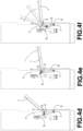
- Figs.4a-4e show different positions of the door and of the elements of the movement device (lever 3, roller 4, spring 6, damper 7, stem 9, plate 11) during the opening stroke, from the closed door of Fig.4a to the fully open door of Fig.4e . More specifically, it can be seen that spring 6 and damper 7 rotate counterclockwise around their lower mounting pins to the position in Fig.4d , where lever 3 is arranged horizontally, and then rotate slightly clockwise in the final stretch of the stroke to Fig.4e where lever 3 is tilted upwards.
- roller 4 starts from the outer end of the track forming the pushing element 13, descending along the curved part ( Fig.4b ) and then ascending along the sloping part ( Fig.4c ) to reach the inner end at the beginning of the horizontal part ( Fig.4d ), and finally moves back slightly ( Fig.4e ).
- the shape, size and position of the pushing element 13 are related to the position of roller 4 with respect to the axis of rotation of door 1, so it is clear that the one depicted is only an exemplary shape that any person skilled in the art can easily modify in case of a different position of roller 4 on lever 3.
- stem 9 is retracted and brings with it plate 11 so that spring 6 can recall lever 3 with a counterclockwise rotation, the rotation speed being limited by the fact that roller 4 continues to rest on the pushing element 13, so it is the retraction speed of stem 9 that determines the time necessary for the closing (usually in the order of 10-15 seconds).
- the safety control during closing is intrinsic in the structure of the movement device, since actuator 8 does not act on lever 3 which is rotated only by the action of spring 6, which is selected to have a recall force sufficient to close door 1 but not such as to cause damage to any obstacle.
- damper 7 ensures that the subsequent closing performed when spring 6 succeeds in recalling door 1 takes place at a limited speed, even if roller 4 is not in contact with the pushing element 13.
- the appliance is also provided with an "active" latch which provides for the compression phase of a seal, if any, at the end of the closing movement of the door, as well as for the detachment of the door from the seal at the beginning of the opening movement, so that the ageing of the seal does not affect the correct functioning of the safety control.
- the latch acts on a horizontal eyelet 14, fixed to the door 1, which is engaged by the free end of an inverted hook 15 swinging around a horizontal pin 16, under the action of a connecting rod 17 pivoted at the other end of hook 15.
- the connecting rod 17 is pivoted at its opposite end to a crank of a crankshaft 18, which rotates counterclockwise about a horizontal axis 19 being driven by a unidirectional motor 20.
- the engagement position of Fig.5 is preferably confirmed by means of a sensor that detects the presence of door 1 when it arrives in the vicinity of the latch in such a position that eyelet 14 can be engaged by hook 15, preferably a Reed sensor (not shown) that detects a magnet 23 mounted on door 1.
- a control unit (not shown), once it receives confirmation from the aforementioned position sensor, activates motor 20 so that the rotation of crankshaft 18 causes the backward movement of the connecting rod 17 which rotates hook 15 clockwise around the pin 16.
- hook 15 pulls inwards eyelet 14 and therefore door 1, which compresses seal 24 without the need for a push by actuator 8.
- a microswitch (not shown) is actuated by hook 15 when the fully closed position of door 1 is reached in which seal 24 is compressed ( Fig.6 ), so as to authorize the start of the washing cycle.
- the crankshaft 18 is also provided with a cam profile 21 that is able to operate a second microswitch 22 that is used to detect the position in which hook 15 has disengaged from eyelet 14 ( Fig.7 ), so as to authorize the activation of actuator 8 for the start of the opening phase.
- a second microswitch 22 that is used to detect the position in which hook 15 has disengaged from eyelet 14 ( Fig.7 ), so as to authorize the activation of actuator 8 for the start of the opening phase. Note that in the passage from the locked position of Fig.6 to this disengagement position, the central portion of hook 15 comes into contact with eyelet 14, pushing it outwards. In this way, door 1 is detached from seal 24 even before the start of the opening phase, without the need for intervention by actuator 8.
- the rotation mechanism of hook 15 could also be different from the connecting rod 17+crankshaft 18 combination, and the rotation pin 16 of hook 15 could be vertical if the mechanism is intended to act on an eyelet 14 arranged in the vertical plane.
- hook 15 could be reversed and pivot 16 located below eyelet 14 to engage it from below, in which case motor 20 would rotate clockwise.
- engagement element on door 1 could also be different from eyelet 14, whereby the latch could be consequently modified in the structure and movement of its element that goes to engage the engagement element on the door.
Landscapes
- Power-Operated Mechanisms For Wings (AREA)
Claims (12)
- Gerät mit einer automatischen Gelenktür (1), einer motorisierten Vorrichtung für die Bewegung der Tür (1) und mindestens einem Sensor, der in der Lage ist, die Störung durch ein Hindernis während der Bewegung der Tür (1) zu erkennen und über eine Steuerungseinheit des Geräts einen Stopp-/Rückwärtsbefehl an die motorisierte Vorrichtung zu senden,
dadurch gekennzeichnet, dass die Türbewegungsvorrichtung mindestens einen linearen Aktuator (8) umfasst, der nur während der Öffnungsphase auf die Tür (1) einwirkt und durch ein elastisches Sicherheitselement eine Relativbewegung zwischen dem linearen Aktuator (8) und der Tür (1) im Falle eines Hindernisses während der Öffnung ermöglicht, wobei der Störungssensor in der Lage ist, die Relativbewegung festzustellen, wobei die Schließphase durch mindestens ein elastisches Rückstellelement (6) ausgeführt wird, das zwischen der Tür (1) und einem festen Teil des Geräts angeordnet ist, wobei die Betätigungsgeschwindigkeit des elastischen Rückstellelements (6) durch den linearen Aktuator (8) während seines Rückhubs und/oder durch mindestens ein Dämpfungselement (7) begrenzt wird, das zwischen der Tür (1) und einem festen Teil des Geräts angeordnet ist. - Gerät nach Anspruch 1, dadurch gekennzeichnet, dass die Tür (1) unten gelenkig ist, sodass sie sich um eine horizontale Achse (2) herum dreht, und mit mindestens einem Hebel (3) bereitgestellt wird, der sich nach innen und unten erstreckt und eine Rolle (4) mit horizontaler Achse trägt, das elastische Rückstellelement (6) und das Dämpfungselement (7) mit dem Hebel (3) verbunden sind, wobei der lineare Aktuator (8) vertikal angeordnet ist und ein Schiebeelement (13) trägt, das die Rolle (4) nach oben schiebt und als Bahn für das Rollen der Rolle (4) ausgebildet ist.
- Gerät nach dem vorstehenden Anspruch, dadurch gekennzeichnet, dass der lineare Aktuator (8) einen ausziehbaren Schaft (9) mit einem Abschnitt (9a) mit verringertem Querschnitt aufweist, auf den das elastische Sicherheitselement in Form einer Schraubenfeder (10) aufgefädelt ist, wobei eine vertikale Platte (11) mit einer im Wesentlichen umgekehrten L-Form von dem Schaft (9) durch zwei vertikal ausgerichtete Kragen (11a, 11b) getragen wird, die mit minimalem Spiel an den Abschnitt (9a) mit reduziertem Querschnitt oberhalb der Spule (10) angeschlossen sind, wobei der Schaft (9) in einem Abschnitt endet, der einen größeren Querschnitt als der Abschnitt (9a) mit reduziertem Querschnitt aufweist.
- Gerät nach dem vorstehenden Anspruch,
dadurch gekennzeichnet, dass die vertikale Platte (11) einen Mikroschalter (12) trägt, der oberhalb des linearen Aktuators (8) derart angeordnet ist, dass ein bewegliches Element (12a) des Mikroschalters (12) vertikal mit dem Schaft (9) in einem solchen Abstand ausgerichtet ist, dass eine Relativbewegung zwischen dem Schaft (9) und der Platte (11) im Falle des Zusammendrückens der auf den Schaft (9) geschraubten Schraubenfeder (10) festgestellt werden kann. - Gerät nach Anspruch 3 oder 4, dadurch gekennzeichnet, dass das Schiebeelement (13) in Sequenz von innen nach außen einen flachen horizontalen Teil, einen flachen nach unten geneigten Teil und einen gekrümmten Teil aufweist, der nach oben ragt, bis er den inneren horizontalen Teil überragt, wobei das Schiebeelement (13) vorzugsweise in einer im Wesentlichen horizontalen Position auf der vertikalen Platte (11) angeordnet ist.
- Gerät nach einem der vorstehenden Ansprüche,
dadurch gekennzeichnet, dass es mindestens ein elastisches Rückstellelement (6) auf beiden Seiten der Tür (1) und nur einen linearen Aktuator (8) und nur ein Dämpfungselement (7) umfasst, die vorzugsweise auf ein und derselben Seite der Tür (1) angeordnet sind. - Gerät nach einem der vorstehenden Ansprüche,
dadurch gekennzeichnet, dass es ferner einen motorisierten Riegel umfasst, der in die Tür (1) eingreift, um sie die letzte Streckung des Schließhubs und die erste Streckung des Öffnungshubs ausführen zu lassen, wobei die Länge der unter der Wirkung des motorisierten Riegels ausgeführten Streckung ausreicht, um das Zusammendrücken einer Dichtung (24), die in Übereinstimmung mit dem Anlagebereich der Tür (1) angeordnet ist, und das anschließende Lösen der Tür (1) von der Dichtung (24) während der Öffnungsphase zu erhalten. - Gerät nach dem vorstehenden Anspruch,
dadurch gekennzeichnet, dass die Tür (1) mit einer Öse (14) versehen ist und der Riegel einen Haken (15) umfasst, der um einen Stift (16) parallel zur Ebene der Öse (14) zwischen einer Verriegelungsposition, in der er in die Öse (14) eingreift und die Tür (1) nach innen zieht, bis er die Dichtung (24) zusammendrückt, und einer Position, in der er nicht in die Öse (14) eingreift, pendelt, wobei die Schwingung zwischen der Verriegelungsposition und der Entriegelungsposition einen Druck des Hakens (15) auf die Öse (14) impliziert, sodass die Tür (1) von der Dichtung (24) getrennt werden kann. - Gerät nach dem vorstehenden Anspruch, dadurch gekennzeichnet, dass der Haken (15) unter der Wirkung einer Verbindungsstange (17) oszilliert, die zwischen dem Haken (15) und einer Kurbel einer Kurbelwelle (18), die von einem unidirektionalen Motor (20) angetrieben wird, angelenkt ist.
- Gerät nach dem vorstehenden Anspruch,
dadurch gekennzeichnet, dass die Kurbelwelle (18) mit einem Nockenprofil (21) versehen ist, das so angeordnet ist, dass es einen Mikroschalter (22) in Übereinstimmung mit der Entriegelungsposition des Hakens (15) betätigt, wobei der Mikroschalter (22) funktionell mit der Steuereinheit verbunden ist, um die Aktivierung des Aktuators (8) zum Starten der Öffnungsphase zuzulassen. - Gerät nach einem der Ansprüche 8 bis 10,
dadurch gekennzeichnet, dass es ferner einen Mikroschalter umfasst, der durch den Haken (15) in Übereinstimmung mit seiner Verriegelungsposition aktiviert wird, wobei der Mikroschalter funktionell mit der Steuereinheit verbunden ist, um den Beginn des Betriebszyklus des Geräts zu autorisieren. - Gerät nach einem der Ansprüche 7 bis 11,
dadurch gekennzeichnet, dass es ferner einen Sensor umfasst, der das Vorhandensein der Tür (1) erkennt, wenn sie in der Nähe des Riegels in einer Position ankommt, in der sie in den Riegel eingreifen kann, vorzugsweise einen Reed-Sensor, der einen an der Tür (1) montierten Magneten (23) erkennt.
Priority Applications (3)
| Application Number | Priority Date | Filing Date | Title |
|---|---|---|---|
| ES21214713T ES2992421T3 (es) | 2021-12-15 | 2021-12-15 | Aparato con puerta batiente |
| EP21214713.6A EP4198239B1 (de) | 2021-12-15 | 2021-12-15 | Haushaltsgerät mit schwenkbarem flügel |
| PL21214713.6T PL4198239T3 (pl) | 2021-12-15 | 2021-12-15 | Urządzenie z drzwiami zawiasowymi |
Applications Claiming Priority (1)
| Application Number | Priority Date | Filing Date | Title |
|---|---|---|---|
| EP21214713.6A EP4198239B1 (de) | 2021-12-15 | 2021-12-15 | Haushaltsgerät mit schwenkbarem flügel |
Publications (3)
| Publication Number | Publication Date |
|---|---|
| EP4198239A1 EP4198239A1 (de) | 2023-06-21 |
| EP4198239C0 EP4198239C0 (de) | 2024-09-11 |
| EP4198239B1 true EP4198239B1 (de) | 2024-09-11 |
Family
ID=79730066
Family Applications (1)
| Application Number | Title | Priority Date | Filing Date |
|---|---|---|---|
| EP21214713.6A Active EP4198239B1 (de) | 2021-12-15 | 2021-12-15 | Haushaltsgerät mit schwenkbarem flügel |
Country Status (3)
| Country | Link |
|---|---|
| EP (1) | EP4198239B1 (de) |
| ES (1) | ES2992421T3 (de) |
| PL (1) | PL4198239T3 (de) |
Family Cites Families (3)
| Publication number | Priority date | Publication date | Assignee | Title |
|---|---|---|---|---|
| IT201700028318A1 (it) * | 2017-03-14 | 2018-09-14 | C M I Cerniere Mecc Industriali Srl | Dispositivo a cerniera motorizzata |
| CN108643752B (zh) * | 2018-04-12 | 2024-04-12 | 佛山市顺德区美的洗涤电器制造有限公司 | 家用电器 |
| EP3685707B1 (de) * | 2019-01-22 | 2024-02-28 | Carrier Corporation | Verkaufskühlvitrine |
-
2021
- 2021-12-15 EP EP21214713.6A patent/EP4198239B1/de active Active
- 2021-12-15 PL PL21214713.6T patent/PL4198239T3/pl unknown
- 2021-12-15 ES ES21214713T patent/ES2992421T3/es active Active
Also Published As
| Publication number | Publication date |
|---|---|
| EP4198239C0 (de) | 2024-09-11 |
| ES2992421T3 (es) | 2024-12-12 |
| PL4198239T3 (pl) | 2024-12-02 |
| EP4198239A1 (de) | 2023-06-21 |
Similar Documents
| Publication | Publication Date | Title |
|---|---|---|
| EP2927603B1 (de) | Haushaltsgerät umfassend ein Türöffnungssystem | |
| US5839357A (en) | Electric pressure cooker | |
| US9585509B2 (en) | Cooking appliance | |
| CN206539153U (zh) | 一种烤箱门锁及包括该烤箱门锁的烤箱 | |
| EP2397626A1 (de) | Türverriegelungsvorrichtung mit Thermoaktuator für Haushaltsgeräte | |
| EP4198239B1 (de) | Haushaltsgerät mit schwenkbarem flügel | |
| EP1935313B1 (de) | Eingebautes Haushaltsgerät mit an seiner Tür angebrachter dekorativer Vorsatzplatte | |
| EP2912984A1 (de) | Scharnier für Türen von Haushaltsgeräten | |
| CN216788052U (zh) | 用于家用电器的门锁机构及家用电器 | |
| KR102432825B1 (ko) | 래치 모듈, 그 제어 방법 및 이를 적용한 조리기기 | |
| EP4212086A1 (de) | Gerät mit scharniertür | |
| CN211795867U (zh) | 蒸烤装置 | |
| EP0669098A1 (de) | Waschmaschine, insbesondere Geschirrspülmaschine, mit dekorativem Frontabdeckpaneel | |
| CN218219890U (zh) | 烹饪器具的开盖结构及烹饪器具 | |
| EP1374753B1 (de) | Haushaltgerät mit einer auf der Tür aufgebrachten Dekorplatte | |
| CN112438679A (zh) | 一种门体防护装置、洗碗机及洗碗机的控制方法 | |
| EP3444531A1 (de) | Türöffnungssystem für ein küchengerät | |
| CN108350715B (zh) | 具有通气开启可能性的铰链装置 | |
| US9631405B2 (en) | Securing mechanism for closing a door, in particular an appliance | |
| CN223438462U (zh) | 一种家用电器 | |
| CN223614781U (zh) | 一种家用电器 | |
| CN221511628U (zh) | 自动开关盖结构及电饭煲 | |
| EP1862579B1 (de) | Von oben befüllbare Waschmaschine mit vorderer Steuervorrichtung im Deckel | |
| CN216602596U (zh) | 料理机 | |
| KR102767611B1 (ko) | 오토 오픈 도어락 장치 |
Legal Events
| Date | Code | Title | Description |
|---|---|---|---|
| PUAI | Public reference made under article 153(3) epc to a published international application that has entered the european phase |
Free format text: ORIGINAL CODE: 0009012 |
|
| STAA | Information on the status of an ep patent application or granted ep patent |
Free format text: STATUS: THE APPLICATION HAS BEEN PUBLISHED |
|
| AK | Designated contracting states |
Kind code of ref document: A1 Designated state(s): AL AT BE BG CH CY CZ DE DK EE ES FI FR GB GR HR HU IE IS IT LI LT LU LV MC MK MT NL NO PL PT RO RS SE SI SK SM TR |
|
| STAA | Information on the status of an ep patent application or granted ep patent |
Free format text: STATUS: REQUEST FOR EXAMINATION WAS MADE |
|
| 17P | Request for examination filed |
Effective date: 20231020 |
|
| RBV | Designated contracting states (corrected) |
Designated state(s): AL AT BE BG CH CY CZ DE DK EE ES FI FR GB GR HR HU IE IS IT LI LT LU LV MC MK MT NL NO PL PT RO RS SE SI SK SM TR |
|
| GRAP | Despatch of communication of intention to grant a patent |
Free format text: ORIGINAL CODE: EPIDOSNIGR1 |
|
| RIC1 | Information provided on ipc code assigned before grant |
Ipc: E05F 15/616 20150101ALI20240304BHEP Ipc: E05F 15/40 20150101AFI20240304BHEP |
|
| STAA | Information on the status of an ep patent application or granted ep patent |
Free format text: STATUS: GRANT OF PATENT IS INTENDED |
|
| INTG | Intention to grant announced |
Effective date: 20240411 |
|
| GRAS | Grant fee paid |
Free format text: ORIGINAL CODE: EPIDOSNIGR3 |
|
| GRAA | (expected) grant |
Free format text: ORIGINAL CODE: 0009210 |
|
| STAA | Information on the status of an ep patent application or granted ep patent |
Free format text: STATUS: THE PATENT HAS BEEN GRANTED |
|
| AK | Designated contracting states |
Kind code of ref document: B1 Designated state(s): AL AT BE BG CH CY CZ DE DK EE ES FI FR GB GR HR HU IE IS IT LI LT LU LV MC MK MT NL NO PL PT RO RS SE SI SK SM TR |
|
| REG | Reference to a national code |
Ref country code: GB Ref legal event code: FG4D |
|
| REG | Reference to a national code |
Ref country code: CH Ref legal event code: EP |
|
| REG | Reference to a national code |
Ref country code: DE Ref legal event code: R096 Ref document number: 602021018612 Country of ref document: DE |
|
| REG | Reference to a national code |
Ref country code: IE Ref legal event code: FG4D |
|
| U01 | Request for unitary effect filed |
Effective date: 20241003 |
|
| U07 | Unitary effect registered |
Designated state(s): AT BE BG DE DK EE FI FR IT LT LU LV MT NL PT RO SE SI Effective date: 20241025 |
|
| REG | Reference to a national code |
Ref country code: ES Ref legal event code: FG2A Ref document number: 2992421 Country of ref document: ES Kind code of ref document: T3 Effective date: 20241212 |
|
| PG25 | Lapsed in a contracting state [announced via postgrant information from national office to epo] |
Ref country code: NO Free format text: LAPSE BECAUSE OF FAILURE TO SUBMIT A TRANSLATION OF THE DESCRIPTION OR TO PAY THE FEE WITHIN THE PRESCRIBED TIME-LIMIT Effective date: 20241211 |
|
| PG25 | Lapsed in a contracting state [announced via postgrant information from national office to epo] |
Ref country code: GR Free format text: LAPSE BECAUSE OF FAILURE TO SUBMIT A TRANSLATION OF THE DESCRIPTION OR TO PAY THE FEE WITHIN THE PRESCRIBED TIME-LIMIT Effective date: 20241212 |
|
| U20 | Renewal fee for the european patent with unitary effect paid |
Year of fee payment: 4 Effective date: 20241217 |
|
| PG25 | Lapsed in a contracting state [announced via postgrant information from national office to epo] |
Ref country code: HR Free format text: LAPSE BECAUSE OF FAILURE TO SUBMIT A TRANSLATION OF THE DESCRIPTION OR TO PAY THE FEE WITHIN THE PRESCRIBED TIME-LIMIT Effective date: 20240911 |
|
| PG25 | Lapsed in a contracting state [announced via postgrant information from national office to epo] |
Ref country code: RS Free format text: LAPSE BECAUSE OF FAILURE TO SUBMIT A TRANSLATION OF THE DESCRIPTION OR TO PAY THE FEE WITHIN THE PRESCRIBED TIME-LIMIT Effective date: 20241211 |
|
| PG25 | Lapsed in a contracting state [announced via postgrant information from national office to epo] |
Ref country code: RS Free format text: LAPSE BECAUSE OF FAILURE TO SUBMIT A TRANSLATION OF THE DESCRIPTION OR TO PAY THE FEE WITHIN THE PRESCRIBED TIME-LIMIT Effective date: 20241211 Ref country code: NO Free format text: LAPSE BECAUSE OF FAILURE TO SUBMIT A TRANSLATION OF THE DESCRIPTION OR TO PAY THE FEE WITHIN THE PRESCRIBED TIME-LIMIT Effective date: 20241211 Ref country code: HR Free format text: LAPSE BECAUSE OF FAILURE TO SUBMIT A TRANSLATION OF THE DESCRIPTION OR TO PAY THE FEE WITHIN THE PRESCRIBED TIME-LIMIT Effective date: 20240911 Ref country code: GR Free format text: LAPSE BECAUSE OF FAILURE TO SUBMIT A TRANSLATION OF THE DESCRIPTION OR TO PAY THE FEE WITHIN THE PRESCRIBED TIME-LIMIT Effective date: 20241212 |
|
| PG25 | Lapsed in a contracting state [announced via postgrant information from national office to epo] |
Ref country code: IS Free format text: LAPSE BECAUSE OF FAILURE TO SUBMIT A TRANSLATION OF THE DESCRIPTION OR TO PAY THE FEE WITHIN THE PRESCRIBED TIME-LIMIT Effective date: 20250111 |
|
| PG25 | Lapsed in a contracting state [announced via postgrant information from national office to epo] |
Ref country code: SM Free format text: LAPSE BECAUSE OF FAILURE TO SUBMIT A TRANSLATION OF THE DESCRIPTION OR TO PAY THE FEE WITHIN THE PRESCRIBED TIME-LIMIT Effective date: 20240911 |
|
| PGFP | Annual fee paid to national office [announced via postgrant information from national office to epo] |
Ref country code: ES Payment date: 20250131 Year of fee payment: 4 |
|
| PG25 | Lapsed in a contracting state [announced via postgrant information from national office to epo] |
Ref country code: CZ Free format text: LAPSE BECAUSE OF FAILURE TO SUBMIT A TRANSLATION OF THE DESCRIPTION OR TO PAY THE FEE WITHIN THE PRESCRIBED TIME-LIMIT Effective date: 20240911 |
|
| PG25 | Lapsed in a contracting state [announced via postgrant information from national office to epo] |
Ref country code: SK Free format text: LAPSE BECAUSE OF FAILURE TO SUBMIT A TRANSLATION OF THE DESCRIPTION OR TO PAY THE FEE WITHIN THE PRESCRIBED TIME-LIMIT Effective date: 20240911 |
|
| PG25 | Lapsed in a contracting state [announced via postgrant information from national office to epo] |
Ref country code: MC Free format text: LAPSE BECAUSE OF FAILURE TO SUBMIT A TRANSLATION OF THE DESCRIPTION OR TO PAY THE FEE WITHIN THE PRESCRIBED TIME-LIMIT Effective date: 20240911 |
|
| PLBE | No opposition filed within time limit |
Free format text: ORIGINAL CODE: 0009261 |
|
| STAA | Information on the status of an ep patent application or granted ep patent |
Free format text: STATUS: NO OPPOSITION FILED WITHIN TIME LIMIT |
|
| REG | Reference to a national code |
Ref country code: CH Ref legal event code: PL |
|
| 26N | No opposition filed |
Effective date: 20250612 |
|
| PG25 | Lapsed in a contracting state [announced via postgrant information from national office to epo] |
Ref country code: CH Free format text: LAPSE BECAUSE OF NON-PAYMENT OF DUE FEES Effective date: 20241231 |
|
| PG25 | Lapsed in a contracting state [announced via postgrant information from national office to epo] |
Ref country code: IE Free format text: LAPSE BECAUSE OF NON-PAYMENT OF DUE FEES Effective date: 20241215 |
|
| U20 | Renewal fee for the european patent with unitary effect paid |
Year of fee payment: 5 Effective date: 20251202 |
|
| PGFP | Annual fee paid to national office [announced via postgrant information from national office to epo] |
Ref country code: GB Payment date: 20251219 Year of fee payment: 5 |
|
| PGFP | Annual fee paid to national office [announced via postgrant information from national office to epo] |
Ref country code: PL Payment date: 20251121 Year of fee payment: 5 |