EP4198230A1 - Hinge - Google Patents
Hinge Download PDFInfo
- Publication number
- EP4198230A1 EP4198230A1 EP21214287.1A EP21214287A EP4198230A1 EP 4198230 A1 EP4198230 A1 EP 4198230A1 EP 21214287 A EP21214287 A EP 21214287A EP 4198230 A1 EP4198230 A1 EP 4198230A1
- Authority
- EP
- European Patent Office
- Prior art keywords
- hinge
- actuating element
- hinge cup
- cup
- articulated lever
- Prior art date
- Legal status (The legal status is an assumption and is not a legal conclusion. Google has not performed a legal analysis and makes no representation as to the accuracy of the status listed.)
- Pending
Links
Images


Classifications
-
- E—FIXED CONSTRUCTIONS
- E05—LOCKS; KEYS; WINDOW OR DOOR FITTINGS; SAFES
- E05D—HINGES OR SUSPENSION DEVICES FOR DOORS, WINDOWS OR WINGS
- E05D3/00—Hinges with pins
- E05D3/06—Hinges with pins with two or more pins
- E05D3/14—Hinges with pins with two or more pins with four parallel pins and two arms
- E05D3/142—Hinges with pins with two or more pins with four parallel pins and two arms with at least one of the hinge parts having a cup-shaped fixing part, e.g. for attachment to cabinets or furniture
-
- E—FIXED CONSTRUCTIONS
- E05—LOCKS; KEYS; WINDOW OR DOOR FITTINGS; SAFES
- E05D—HINGES OR SUSPENSION DEVICES FOR DOORS, WINDOWS OR WINGS
- E05D5/00—Construction of single parts, e.g. the parts for attachment
- E05D5/02—Parts for attachment, e.g. flaps
- E05D5/0276—Parts for attachment, e.g. flaps for attachment to cabinets or furniture, the hinge having two or more pins
-
- E—FIXED CONSTRUCTIONS
- E05—LOCKS; KEYS; WINDOW OR DOOR FITTINGS; SAFES
- E05F—DEVICES FOR MOVING WINGS INTO OPEN OR CLOSED POSITION; CHECKS FOR WINGS; WING FITTINGS NOT OTHERWISE PROVIDED FOR, CONCERNED WITH THE FUNCTIONING OF THE WING
- E05F5/00—Braking devices, e.g. checks; Stops; Buffers
- E05F5/006—Braking devices, e.g. checks; Stops; Buffers for hinges having a cup-shaped fixing part, e.g. for attachment to cabinets or furniture
-
- E—FIXED CONSTRUCTIONS
- E05—LOCKS; KEYS; WINDOW OR DOOR FITTINGS; SAFES
- E05F—DEVICES FOR MOVING WINGS INTO OPEN OR CLOSED POSITION; CHECKS FOR WINGS; WING FITTINGS NOT OTHERWISE PROVIDED FOR, CONCERNED WITH THE FUNCTIONING OF THE WING
- E05F5/00—Braking devices, e.g. checks; Stops; Buffers
- E05F5/02—Braking devices, e.g. checks; Stops; Buffers specially for preventing the slamming of swinging wings during final closing movement, e.g. jamb stops
-
- E—FIXED CONSTRUCTIONS
- E05—LOCKS; KEYS; WINDOW OR DOOR FITTINGS; SAFES
- E05Y—INDEXING SCHEME RELATING TO HINGES OR OTHER SUSPENSION DEVICES FOR DOORS, WINDOWS OR WINGS AND DEVICES FOR MOVING WINGS INTO OPEN OR CLOSED POSITION, CHECKS FOR WINGS AND WING FITTINGS NOT OTHERWISE PROVIDED FOR, CONCERNED WITH THE FUNCTIONING OF THE WING
- E05Y2201/00—Constructional elements; Accessories therefore
- E05Y2201/10—Covers; Housings
- E05Y2201/11—Covers
-
- E—FIXED CONSTRUCTIONS
- E05—LOCKS; KEYS; WINDOW OR DOOR FITTINGS; SAFES
- E05Y—INDEXING SCHEME RELATING TO HINGES OR OTHER SUSPENSION DEVICES FOR DOORS, WINDOWS OR WINGS AND DEVICES FOR MOVING WINGS INTO OPEN OR CLOSED POSITION, CHECKS FOR WINGS AND WING FITTINGS NOT OTHERWISE PROVIDED FOR, CONCERNED WITH THE FUNCTIONING OF THE WING
- E05Y2201/00—Constructional elements; Accessories therefore
- E05Y2201/20—Brakes; Disengaging means, e.g. clutches; Holders, e.g. locks; Stops; Accessories therefore
- E05Y2201/23—Actuation thereof
- E05Y2201/232—Actuation thereof by automatically acting means
- E05Y2201/24—Actuation thereof by automatically acting means using lost motion
-
- E—FIXED CONSTRUCTIONS
- E05—LOCKS; KEYS; WINDOW OR DOOR FITTINGS; SAFES
- E05Y—INDEXING SCHEME RELATING TO HINGES OR OTHER SUSPENSION DEVICES FOR DOORS, WINDOWS OR WINGS AND DEVICES FOR MOVING WINGS INTO OPEN OR CLOSED POSITION, CHECKS FOR WINGS AND WING FITTINGS NOT OTHERWISE PROVIDED FOR, CONCERNED WITH THE FUNCTIONING OF THE WING
- E05Y2201/00—Constructional elements; Accessories therefore
- E05Y2201/20—Brakes; Disengaging means, e.g. clutches; Holders, e.g. locks; Stops; Accessories therefore
- E05Y2201/262—Brakes; Disengaging means, e.g. clutches; Holders, e.g. locks; Stops; Accessories therefore characterised by type of motion
- E05Y2201/264—Brakes; Disengaging means, e.g. clutches; Holders, e.g. locks; Stops; Accessories therefore characterised by type of motion linear
-
- E—FIXED CONSTRUCTIONS
- E05—LOCKS; KEYS; WINDOW OR DOOR FITTINGS; SAFES
- E05Y—INDEXING SCHEME RELATING TO HINGES OR OTHER SUSPENSION DEVICES FOR DOORS, WINDOWS OR WINGS AND DEVICES FOR MOVING WINGS INTO OPEN OR CLOSED POSITION, CHECKS FOR WINGS AND WING FITTINGS NOT OTHERWISE PROVIDED FOR, CONCERNED WITH THE FUNCTIONING OF THE WING
- E05Y2201/00—Constructional elements; Accessories therefore
- E05Y2201/60—Suspension or transmission members; Accessories therefore
- E05Y2201/622—Suspension or transmission members elements
- E05Y2201/624—Arms
-
- E—FIXED CONSTRUCTIONS
- E05—LOCKS; KEYS; WINDOW OR DOOR FITTINGS; SAFES
- E05Y—INDEXING SCHEME RELATING TO HINGES OR OTHER SUSPENSION DEVICES FOR DOORS, WINDOWS OR WINGS AND DEVICES FOR MOVING WINGS INTO OPEN OR CLOSED POSITION, CHECKS FOR WINGS AND WING FITTINGS NOT OTHERWISE PROVIDED FOR, CONCERNED WITH THE FUNCTIONING OF THE WING
- E05Y2201/00—Constructional elements; Accessories therefore
- E05Y2201/60—Suspension or transmission members; Accessories therefore
- E05Y2201/622—Suspension or transmission members elements
- E05Y2201/638—Cams; Ramps
-
- E—FIXED CONSTRUCTIONS
- E05—LOCKS; KEYS; WINDOW OR DOOR FITTINGS; SAFES
- E05Y—INDEXING SCHEME RELATING TO HINGES OR OTHER SUSPENSION DEVICES FOR DOORS, WINDOWS OR WINGS AND DEVICES FOR MOVING WINGS INTO OPEN OR CLOSED POSITION, CHECKS FOR WINGS AND WING FITTINGS NOT OTHERWISE PROVIDED FOR, CONCERNED WITH THE FUNCTIONING OF THE WING
- E05Y2201/00—Constructional elements; Accessories therefore
- E05Y2201/60—Suspension or transmission members; Accessories therefore
- E05Y2201/622—Suspension or transmission members elements
- E05Y2201/682—Pins
-
- E—FIXED CONSTRUCTIONS
- E05—LOCKS; KEYS; WINDOW OR DOOR FITTINGS; SAFES
- E05Y—INDEXING SCHEME RELATING TO HINGES OR OTHER SUSPENSION DEVICES FOR DOORS, WINDOWS OR WINGS AND DEVICES FOR MOVING WINGS INTO OPEN OR CLOSED POSITION, CHECKS FOR WINGS AND WING FITTINGS NOT OTHERWISE PROVIDED FOR, CONCERNED WITH THE FUNCTIONING OF THE WING
- E05Y2800/00—Details, accessories and auxiliary operations not otherwise provided for
- E05Y2800/26—Form, shape
- E05Y2800/266—Form, shape curved
-
- E—FIXED CONSTRUCTIONS
- E05—LOCKS; KEYS; WINDOW OR DOOR FITTINGS; SAFES
- E05Y—INDEXING SCHEME RELATING TO HINGES OR OTHER SUSPENSION DEVICES FOR DOORS, WINDOWS OR WINGS AND DEVICES FOR MOVING WINGS INTO OPEN OR CLOSED POSITION, CHECKS FOR WINGS AND WING FITTINGS NOT OTHERWISE PROVIDED FOR, CONCERNED WITH THE FUNCTIONING OF THE WING
- E05Y2800/00—Details, accessories and auxiliary operations not otherwise provided for
- E05Y2800/26—Form, shape
- E05Y2800/292—Form, shape having apertures
- E05Y2800/296—Slots
-
- E—FIXED CONSTRUCTIONS
- E05—LOCKS; KEYS; WINDOW OR DOOR FITTINGS; SAFES
- E05Y—INDEXING SCHEME RELATING TO HINGES OR OTHER SUSPENSION DEVICES FOR DOORS, WINDOWS OR WINGS AND DEVICES FOR MOVING WINGS INTO OPEN OR CLOSED POSITION, CHECKS FOR WINGS AND WING FITTINGS NOT OTHERWISE PROVIDED FOR, CONCERNED WITH THE FUNCTIONING OF THE WING
- E05Y2900/00—Application of doors, windows, wings or fittings thereof
- E05Y2900/20—Application of doors, windows, wings or fittings thereof for furnitures, e.g. cabinets
Definitions
- the invention relates to a hinge, in particular a furniture hinge, comprising a stop part with which the hinge can be fastened to a fixed furniture part, at least one articulated lever, a hinge cup which is or can be arranged pivotably on the stop part via the at least one articulated lever, the at least one Articulated lever is mounted with the hinge cup via at least one joint axis, the hinge cup being attachable to a movable furniture part, at least one damping device for damping a relative movement between the stop part and the hinge cup between an open position and a closed position of the hinge, the at least one damping device being a linear damper with a piston and a translationally movable piston rod, wherein the at least one damping device is arranged, preferably completely, outside the hinge cup, and at least one, preferably integral and/or spatially separate from the at least one articulated lever, particularly preferably at least in the open position, Actuating element for actuating the at least one damping device. Furthermore, the invention relates to a piece of furniture with
- a disadvantage of the prior art is that the conversion of the rotational movement of the articulated lever into a translational movement of the linearly movable slide results in an inharmonious damping stroke. Furthermore, a force distribution on the linearly movable slide is unfavorable, since a force vector caused by the rotation of the articulated lever orthogonally has on the piston rod, whereby in particular a high wear of the linearly movable slide and / or a reduced power transmission to the linear damper is effected. In addition, the complex geometry of the linearly movable slide must be adapted to the movement of the articulated lever in a complex manner and with low tolerances in order to be able to guarantee the functionality of the hinge.
- the objective technical task of the present invention is therefore to provide an improved hinge compared to the prior art, in which the disadvantages of the prior art are at least partially eliminated, and which is characterized in particular by a compact design and / or a particularly favorable transmission of a Distinguishes rotational movement of the at least one articulated lever on the piston rod in order to be able to ensure in particular a harmonious damping movement.
- the at least one actuating element is rotatably mounted, preferably on the outside, on the hinge cup and the piston rod can be moved, preferably directly, by rotating the at least one actuating element essentially in a translatory manner relative to the linear damper.
- the hinge can be flexibly adapted to modified damping devices—for example, varying geometries and/or dimensions. Added to this is the positive property that the rotational movement of the at least one articulated lever generated in the interior of the hinge cup can be converted into a rotational movement of the at least one actuating element. On the one hand, this has the advantage that the rotational movement of the articulated lever can be translated into the rotational movement of the at least one actuating element depending on the requirements placed on the hinge (e.g.
- the at least one articulated lever may contact the piston rod, preferably directly, for example by reaching through a hinge cup opening.
- the at least one damping device is preferably actuated exclusively in a translatory manner, with a linear movement of the piston rod relative to the linear damper generally being able to be superimposed with a pivoting movement of the at least one damping device.
- a pivoting movement can be inhibited or prevented, for example, via inclined surfaces on the hinge cup and/or a hinge cup cover.
- the at least one actuating element is preferably spatially spaced from the at least one articulated lever in at least one movement section and/or directly contacts the piston rod of the linear damper.
- a piece of furniture comprising at least one fixed furniture part and one movably mounted furniture part, with at least one hinge according to one of the preceding claims, the stop part of the hinge being arranged on the fixed furniture part and the hinge cup on the movable one Arranged furniture part, in particular at least partially integrated in the movable furniture part.
- the hinge is preferably used in furniture bodies with flaps. However, the hinge can also be applied to windows/window frames, doors/door frames or the like in general.
- a power transmission from an interior space of the hinge cup can be passed on particularly favorably to an exterior space of the hinge cup.
- a hinge cup cover is provided, with which the at least one damping device and/or the at least one actuating element can be covered at least in regions, preferably completely, it being preferably provided that the hinge cup cover can be clipped onto the hinge cup or is clipped on and/or comprises at least one receiving area, preferably corresponding to the geometry of the at least one damping device and/or the at least one actuating element.
- the hinge cup cover can reduce contamination of the at least one damping device and/or the at least one actuating element in order to be able to maintain the proper functionality of the hinge over a longer service life. For example, when the hinge is in the position of use, it is possible to prevent chips from getting to component components such as the actuating element or damping device arranged on the outside of the hinge cup and/or from entering an interior space of the hinge cup.
- the at least one damping device and/or the at least one actuating element is/are already preassembled on the outside of the hinge cup, work steps in the final assembly can be reduced.
- the hinge cup and/or the stop element preferably comprises at least one fastening section with which the hinge cup and/or the stop element can be fixed to a piece of furniture via fastening means.
- the hinge cup particularly preferably comprises an inclined surface or inclined plane which is oriented relative to a hinge cup base and on which the at least one damping device can be supported.
- the linear damper can include a return spring and/or be coupled to the at least one actuating element in such a way (for example via a positive fit) that after damping has taken place, a return to a starting position before damping is automatically generated.
- the at least one articulated lever in the closed position and/or the open position of the hinge is arranged at least in regions within the hinge cup in an interior of the hinge cup and/or an exterior of the hinge cup is covered by a cover, preferably separate from a hinge cup cover that may be present /or is at least partially separated from the interior of the hinge cup by an optionally present hinge cup cover, the hinge cup wall.
- the hinge cup has proven to be favorable for the hinge cup to have a recess, a hinge cup base and/or a bearing surface, with the at least one damping device being arranged at least in certain areas in the recess of the hinge cup and/or on the bearing surface of the hinge cup, it preferably being provided that the bearing surface encloses an angle, particularly preferably an acute angle, with respect to the hinge cup base.
- the recess can result in more favorable mounting of the at least one damping device and/or the at least one actuating element, with the bearing surface being able to support the at least one damping device against an undesired pivoting movement in the sense of a bearing.
- the at least one actuating element protrudes through a hinge cup opening into the hinge cup and/or the at least one articulated lever protrudes out of the hinge cup through the hinge cup opening.
- the at least one actuating element is mounted on the hinge cup such that it can rotate about an axis, preferably the at least one joint axis, with a rotational movement of the at least one actuating element being able to be converted into a linear movement of the piston rod of the linear damper, it being preferably provided that the at least one actuating element comprises a cam and/or a particularly preferably convex profiling in the direction of the piston of the linear damper.
- the cam and/or the profiling is preferably convex in the direction of the piston rod in order to be able to ensure a particularly harmonious damping movement.
- an advantageous variant of the present invention consists in that the at least one actuating element is designed as a bent sheet metal part or plastic part, preferably essentially U-shaped.
- At least one actuating element is designed in a U-shape, support on the hinge cup and/or contact with the piston rod can be effected in a particularly favorable manner.
- One embodiment of the invention provides that at least one transmission device is provided, with which a rotational movement of the at least one articulated lever can be translated to the at least one actuating element, it being preferably provided that the at least one transmission device is arranged inside the hinge cup.
- the at least one transmission device can be used to generate an exclusively sectional actuation of the linear damper via the at least one actuating element, with the at least one transmission device preferably being designed to correspond to an at least regional geometry of the at least one actuating element for contacting the at least one actuating element.
- the at least one transmission device can comprise a control disk and/or a receptacle of the at least one articulated lever for the at least one actuating element.
- the at least one transmission device starting from the open position of the hinge in the direction of the closed position of the hinge, is designed without contact with the at least one actuating element in a first movement section and/or in a second, preferably on the first movement section following, movement section is in contact with the at least one actuating element, it being preferably provided that the at least one damping device can be activated by the at least one transmission device, preferably exclusively, in the second movement section.
- the at least one articulated lever reaches an angle at which the at least one transmission device preferably contacts the at least one actuating element for activating the damping, whereby the transmission device can generally be dispensed with and the at least one actuating element can be encompassed by the at least one articulated lever to directly actuate the piston rod.
- the damping of the hinge preferably takes place starting from the open position in the direction of the closed position, with the hinge generally being able to be damped starting from the closed position into the open position—in particular with the two movement sections—alternatively or additionally.
- the at least one transmission device is rotatably arranged on an axis, preferably the at least one articulated axis, and/or is designed as a, preferably integral, part of the at least one articulated lever.
- the at least one transmission device can be arranged at a free end of the at least one articulated lever and/or (in the sense of a dual function) can be mounted around the axis.
- the at least one transmission device comprises a cam and/or a profile, preferably designed as an undercut, for receiving the at least one actuating element.
- the at least one articulated lever comprises the at least one transmission device and/or can be arranged or is arranged indirectly via the at least one transmission device on the at least one actuating element, preferably by a rotational movement of the at least one articulated lever.
- the at least one actuating element is arranged predominantly outside the hinge cup and/or comprises a coupling device with which the at least one transmission device for damping the hinge can be contacted.
- the rotational movement of the at least one articulated lever can be transmitted to the at least one actuating element via the coupling device, the linear damper being actuated by the rotational movement of the at least one actuating element thereby initiated.
- the coupling device is designed in the form of a web, preferably oriented essentially parallel to the at least one joint axis, the web projecting transversely from the at least one actuating element.
- the hinge cup can be protruded through in a particularly favorable manner by means of a web, in which case the hinge cup can be designed to be closed to a large extent.
- the coupling device protrudes through a slot, preferably in the form of an annular segment, into the hinge cup, it being preferably provided that the coupling device has a free end.
- a transmission of rotational movement can be made possible through the elongated hole, in which case the elongated hole can define, for example, a stop as a limit for a damping stroke of the linear damper due to an expansion.
- An advantageous variant of the present invention consists in that the at least one actuating element is connected to the piston rod, preferably via an extension rod arranged transversely and/or orthogonally to the piston rod, it preferably being provided that the piston rod is at least partially within an opening or recess the at least one actuating element is arranged for movement coupling of the piston rod with the at least one actuating element.
- the opening or recess is preferably at a distance from the axis, with varying distances from the axis being able to convert the rotational movement of the at least one articulated lever into a linear movement of the piston rod, since different torques are transmitted to the linear damper.
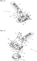
- Fig. 1a shows a hinge 1 in the form of a furniture hinge, comprising a stop part 2, with which the hinge 1 can be fastened to a fixed furniture part 40 (see FIG 7 ), two articulated levers 3, with a first articulated lever 3 covering a further articulated lever 39 in the illustration, and a hinge cup 4, which is pivotably arranged on the stop part 2 via the two articulated levers 3.
- the articulated lever 3 (and the further articulated lever 39) is mounted with the hinge cup 4 via articulation axes 5, with the hinge cup 4 being able to be fastened to a movable furniture part 41.
- Fig. 1b shows an exploded view of the components involved in the hinge 1, with one actuating element 12 being designed as a sheet metal part 25 bent in a U-shape.
- the actuating element 12 can, however, in general (for example in the exemplary embodiment according to Figure 5a ) be designed as a plastic part.
- the hinge 1 comprises a damping device 6 for damping a relative movement between the stop part 2 and the hinge cup 4 between an open position 7 and a closed position 8 of the hinge 1, which is arranged laterally on the hinge cup 4 on the outside.
- the damping device 6 has a linear damper 9 with a piston 10 and a piston rod 11 that can be moved translationally relative to the linear damper 9 , the piston rod 11 being connected to the piston 10 for damping the hinge 1 .
- the joint axis 5, which is more relevant for the transmission of the damping movement, is illustrated as axis 22 in the figures.
- a further damping device 6 can also be provided, which is arranged on the hinge cup 4 symmetrically or mirrored about a longitudinal extension of the hinge 1 .
- the hinge 1 comprises a one-piece and separate actuating element 12 for actuating the at least one damping device 6 , which is spatially spaced from the articulated lever 3 in the open position 7 and contacts the articulated lever 3 in the closed position 8 .
- the damping device 6 is arranged completely outside of the hinge cup 4 .
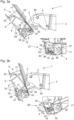
- FIG. 2a shows the arrangement of the damping device 6 and the actuating element 12 relative to a hinge cup cover 13, with which the damping device 6 and the actuating element 12 can be covered.
- the hinge cup cover 13 has on a lateral surface facing the articulated lever 3 fastening means with which the hinge cup cover 13 can be clipped onto the hinge cup 4, with a receiving area 14 being provided which adapts to the geometry of the Damping device 6 and the actuating element 12 is configured correspondingly.
- Figure 2b shows the arrangement Figure 2a in a sectional view through the middle of the hinge cup cover 13.
- the hinge cup cover 13 has a further bearing surface 44 on which the damping device 6 can be supported when the hinge 1 is in the position of use.
- Figure 2c shows the hinge 1 without the hinge cup cover 13, the hinge cup 4 comprising a recess 18, a hinge cup bottom 19 and a bearing surface 20, the damping device 6 being arranged in the recess 18 of the hinge cup 4 and on the bearing surface 20 of the hinge cup 4.
- the bearing surface 20 encloses an acute angle 21 with respect to the hinge cup base 19 .
- the bearing surface 20 can be oriented parallel to the further bearing surface 44 of the hinge cup cover 13, so that the damping device 6 has a firm seat on the hinge cup 4, or it can be arranged relative to the further bearing surface 44 in such a way that a slight rotational movement of the damping device 6 is made possible, which is superimposed with a translational movement of the piston rod 11.
- the bearing surface 20 or the further bearing surface 44 is not absolutely necessary.
- the actuating element 12 protrudes through a hinge cup opening 45 into the hinge cup 4, it also generally being possible for the actuating element 12 to be arranged exclusively outside the hinge cup 4 and the articulated lever 3 to protrude through the hinge cup opening 45 out of the hinge cup 4, with the articulated lever 3 is arranged in some areas inside and in some areas outside of the hinge cup 4 . It is generally also conceivable that the actuating element 12 by the Articulated lever 3 is formed and the rotational movement is transmitted directly to the piston rod 11 of the damping device 6 .
- the rotational movement of the actuating element 12 is picked up by the piston rod 11 on the profile 24, it being possible for a transmission ratio to be changed by changing the spacing of the profile 24 from the axis 22.
- the rotational movement of the articulated lever 3 is tapped off by the actuating element 12 on the coupling device 29, a translation being able to be changed by changing the spacing of the coupling device 29 from the axis 22 (or the positioning of the transmission device 26 on the articulated lever 3).
- the rotational movement is preferably scanned at a free end of the articulated lever 3 and/or the actuating element 12.
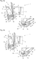
- Figure 3a shows that the actuating element 12 is arranged on the hinge cup 4 in some areas inside and in some areas outside the hinge cup 4 .
- the actuating element 12 is rotatably mounted on the hinge cup 4 on the outside via the joint axis 5 in the form of the axis 22 (formed by a clamp 37).
- the piston rod 11 can be moved translationally relative to the linear damper 9 directly by rotating the actuating element 12 (possibly with a slight pivoting movement of the piston rod 11 and the linear damper 9).
- the hinge 1 includes a transmission device 26, with which a rotational movement of the articulated lever 3 on the actuating element 12 can be implemented.
- the transmission device is arranged inside the hinge cup 4 .
- the transmission device 26 is designed without contact with the actuating element 12 in a first movement section 27, with the hinge 1 being present in the first movement section 27 in the state shown.
- the transmission device 26 is in contact with the actuating element 12 in the direction of the closed position 8 of the hinge 1 (see FIG Figure 3b ).
- the transmission device 26 comprises a cam 23 and a profile 24 in the form of an undercut 43 for receiving the actuating element 12.
- FIG 3b shows the hinge 1 at the beginning of the second movement section 12, the damping device 6 being active through the transmission device 26 exclusively in the second movement section 28.
- the articulated lever 3 is arranged in regions within the hinge cup 4 in an interior space 15 of the hinge cup 4 .
- An outer space 16 of the hinge cup 4 is separated from the inner space 15 of the hinge cup 4 by a hinge cup wall 17 that is separate from the hinge cup cover 13 and spaced from the hinge cup cover 13 in some areas.
- Figure 4a shows that the actuating element 12 is mounted on the hinge pot 4 such that it can rotate about the axis 22 in the form of one of the joint axes 5 .
- the rotational movement of the actuating element 12 can be translated into a linear movement of the piston rod 11 of the linear damper 9 .
- the actuating element 12 comprises a convex in the direction of the piston rod 11 trained cam 23 and a convex profile 24 in the direction of the piston 10 of the linear damper 9.
- the transmission device 26 which is rotatably positioned on the axis 22, is designed as a materially connected part of the articulated lever 3 and is therefore an integral part of the articulated lever 3. In general, however, the transmission device 26 can also be designed as a separate structural component of the hinge 1 or can interact indirectly with the articulated lever 3 stand.
- the articulated lever 3 rotates in the first movement segment 27 about the joint axis 5 until the transmission device 26 contacts the actuating element 12 and during the second movement segment 28 the actuating element 12 rotates in a motion-coupled manner in order to initiate damping via the piston rod 11.
- this movement coupling for damping the hinge 1 is also possible as an alternative or in addition in the course of an opening movement of the hinge 1 .
- the actuating element 12 is for the most part outside (in the outer space 16) of the hinge cup 4 and protrudes into the interior 15 of the hinge cup 4.
- the actuating element 12 comprises a coupling device 29 with which the transmission device 26 for damping the hinge 1 can be contacted.
- the coupling device 29 is designed in the form of a web 30 oriented parallel to the joint axes 5 , the web 30 projecting transversely from the actuating element 12 .
- the coupling device 29 protrudes through a slot 32 in the form of a circular ring segment 31 as a hinge cup opening 45 into the hinge cup 4 .
- the coupling device 29 has a free end 33 .
- Figure 4b differs from Figure 4a only to the effect that the hinge 1 is in the closed position 8 .
- the damping stroke of the damping device 6 has ended, it being possible in general for the damping device 6 to be returned to an initial position of the damping device 6 by means of a return spring or via a movement coupling with the actuating element 12 .
- FIG. 12 shows another preferred exemplary embodiment of the hinge 1 in an exploded view, with the actuating element 12 being connected to the piston rod 11 via an extension rod 34 arranged orthogonally to the piston rod 11 .
- the extension rod 34 of the piston rod 11 is arranged in regions within an opening 35 of the actuating element 12 for movement coupling of the piston rod 11 to the actuating element 12 .
- the opening 35 can generally also be designed as a depression for arranging the extension rod 34 on the actuating element 12 .
- Two of the hinge pins 5 are in the form of a rivet 36 connected to the hinge cup 4 , two of the hinge pins 5 being designed as a clamp 37 connected to the hinge cup 4 .
- the clip 37 forms the axis 22 and a further joint axis 38 for a further joint lever 39.
- the axis 22 can generally also be formed by a rivet 36.
- Figure 5b shows that the articulated lever 3 includes the transmission device 26 .
- the articulated lever 3 it is possible for the articulated lever 3 to be arranged indirectly via the transmission device 26 on the actuating element 12 by a rotational movement of the articulated lever 3 .
- Figure 6a shows the hinge in the second movement section 28, with a rotation of the articulated lever 3 via the coupling device 29 on the Actuating element 12 is transmitted and by the arrangement of the extension rod 34 in the opening 35, the piston rod 11 is moved in translation for damping.
- the linear movement can be superimposed with a rotation of the damping device 6 .
- Figure 6b differs from Figure 6b only to the effect that the hinge is in the closed position 8.
- An end of the damping stroke of the damping device 6 can be generated, for example, by the articulated lever 3 making contact with the hinge cup 4 and/or by a stop of the elongated hole 32 .
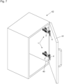
- FIG. 7 shows a piece of furniture 42 comprising a fixed furniture part 40 and a furniture part 41 movably mounted on the fixed furniture part 40 with two hinges 1, the stop part 2 of the hinge 1 being arranged on the fixed furniture part 40.
- the hinge cup 4 of the hinge 1 is arranged on the movable furniture part 41 , the hinge cup 4 being integrated into the movable furniture part 41 .
- the hinge 1 is not limited to use with furniture 42.
- the hinge 1 can, for example, also be used in an analogous manner in a window or a door.
Abstract
Scharnier (1), insbesondere Möbelscharnier, umfassend- ein Anschlagteil (2), mit welchem das Scharnier (1) an einem feststehenden Möbelteil (40) befestigbar ist,- wenigstens einen Gelenkhebel (3),- einen Scharniertopf (4), welcher über den wenigstens einen Gelenkhebel (3) schwenkbar an dem Anschlagteil (2) angeordnet oder anordenbar ist, wobei der wenigstens eine Gelenkhebel (3) mit dem Scharniertopf (4) über wenigstens eine Gelenkachse (5) gelagert ist, wobei der Scharniertopf (4) an einem bewegbaren Möbelteil (41) befestigbar ist,- wenigstens eine Dämpfvorrichtung (6) zur Dämpfung einer Relativbewegung zwischen dem Anschlagteil (2) und dem Scharniertopf (4) zwischen einer Offenstellung (7) und einer Schließstellung (8) des Scharniers (1), wobei die wenigstens eine Dämpfvorrichtung (6) einen Lineardämpfer (9) mit einem Kolben (10) und einer translatorisch bewegbaren Kolbenstange (11) aufweist, wobei die wenigstens eine Dämpfvorrichtung (6), vorzugsweise vollständig, außerhalb des Scharniertopfes (4) angeordnet ist, und- wenigstens ein, vorzugsweise einstückiges und/oder von dem wenigstens einen Gelenkhebel (3), besonders bevorzugt zumindest in der Offenstellung (7) räumlich, gesondertes, Betätigungselement (12) zur Betätigung der wenigstens einen Dämpfvorrichtung (6),wobei das wenigstens eine Betätigungselement (12) rotierbar, vorzugsweise außenseitig, an dem Scharniertopf (4) gelagert ist und die Kolbenstange (11), vorzugsweise unmittelbar, durch eine Rotation des wenigstens einen Betätigungselementes (12) im Wesentlichen translatorisch gegenüber dem Lineardämpfer (9) bewegbar ist.Hinge (1), in particular furniture hinge, comprising- a stop part (2) with which the hinge (1) can be fastened to a fixed furniture part (40), - at least one articulated lever (3), - a hinge cup (4) which has the at least one articulated lever (3) is or can be arranged pivotably on the stop part (2), the at least one articulated lever (3) being mounted with the hinge cup (4) via at least one articulation axis (5), the hinge cup (4) being attached to a movable furniture part (41), - at least one damping device (6) for damping a relative movement between the stop part (2) and the hinge cup (4) between an open position (7) and a closed position (8) of the hinge (1), wherein the at least one damping device (6) has a linear damper (9) with a piston (10) and a translationally movable piston rod (11), wherein the at least one damping device (6) is arranged, preferably completely, outside the hinge cup (4), and- at least one, preferably integral and/or spatially separate from the at least one articulated lever (3), particularly preferably at least in the open position (7), actuating element (12) for actuating the at least one damping device (6), wherein the at least one actuating element (12) is mounted rotatably, preferably on the outside, on the hinge cup (4) and the piston rod (11) can be moved, preferably directly, essentially in a translatory manner relative to the linear damper (9) by rotating the at least one actuating element (12).
Description
Die Erfindung betrifft ein Scharnier, insbesondere Möbelscharnier, umfassend ein Anschlagteil, mit welchem das Scharnier an einem feststehenden Möbelteil befestigbar ist, wenigstens einen Gelenkhebel, einen Scharniertopf, welcher über den wenigstens einen Gelenkhebel schwenkbar an dem Anschlagteil angeordnet oder anordenbar ist, wobei der wenigstens eine Gelenkhebel mit dem Scharniertopf über wenigstens eine Gelenkachse gelagert ist, wobei der Scharniertopf an einem bewegbaren Möbelteil befestigbar ist, wenigstens eine Dämpfvorrichtung zur Dämpfung einer Relativbewegung zwischen dem Anschlagteil und dem Scharniertopf zwischen einer Offenstellung und einer Schließstellung des Scharniers, wobei die wenigstens eine Dämpfvorrichtung einen Lineardämpfer mit einem Kolben und einer translatorisch bewegbaren Kolbenstange aufweist, wobei die wenigstens eine Dämpfvorrichtung, vorzugsweise vollständig, außerhalb des Scharniertopfes angeordnet ist, und wenigstens ein, vorzugsweise einstückiges und/oder von dem wenigstens einen Gelenkhebel, besonders bevorzugt zumindest in der Offenstellung räumlich, gesondertes, Betätigungselement zur Betätigung der wenigstens einen Dämpfvorrichtung. Des Weiteren betrifft die Erfindung ein Möbel mit wenigstens einem solchen Scharnier.The invention relates to a hinge, in particular a furniture hinge, comprising a stop part with which the hinge can be fastened to a fixed furniture part, at least one articulated lever, a hinge cup which is or can be arranged pivotably on the stop part via the at least one articulated lever, the at least one Articulated lever is mounted with the hinge cup via at least one joint axis, the hinge cup being attachable to a movable furniture part, at least one damping device for damping a relative movement between the stop part and the hinge cup between an open position and a closed position of the hinge, the at least one damping device being a linear damper with a piston and a translationally movable piston rod, wherein the at least one damping device is arranged, preferably completely, outside the hinge cup, and at least one, preferably integral and/or spatially separate from the at least one articulated lever, particularly preferably at least in the open position, Actuating element for actuating the at least one damping device. Furthermore, the invention relates to a piece of furniture with at least one such hinge.
Eine solches Scharnier ist bereits aus der Schrift
Nachteilig am Stand der Technik ist, dass durch die Übersetzung der Rotationsbewegung des Gelenkhebels in eine translatorische Bewegung des linear bewegbaren Schiebers ein unharmonischer Dämpfungshub bedingt ist. Des Weiteren ist eine Kraftverteilung auf den linear bewegbaren Schieber ungünstig, da ein durch die Rotation des Gelenkhebels bedingter Kraftvektor orthogonal auf die Kolbenstange weist, wodurch insbesondere ein hoher Verschleiß des linear bewegbaren Schiebers und/oder eine reduzierte Kraftübertragung auf den Lineardämpfer erwirkt wird. Darüber hinaus muss die komplexe Geometrie des linear bewegbaren Schiebers aufwändig und mit geringen Toleranzen an den Bewegungsablauf des Gelenkhebels angepasst sein, um die Funktionalität des Scharniers gewährleisten zu können.A disadvantage of the prior art is that the conversion of the rotational movement of the articulated lever into a translational movement of the linearly movable slide results in an inharmonious damping stroke. Furthermore, a force distribution on the linearly movable slide is unfavorable, since a force vector caused by the rotation of the articulated lever orthogonally has on the piston rod, whereby in particular a high wear of the linearly movable slide and / or a reduced power transmission to the linear damper is effected. In addition, the complex geometry of the linearly movable slide must be adapted to the movement of the articulated lever in a complex manner and with low tolerances in order to be able to guarantee the functionality of the hinge.
Die objektive technische Aufgabe der vorliegenden Erfindung besteht daher darin, ein gegenüber dem Stand der Technik verbessertes Scharnier anzugeben, bei welchem die Nachteile des Standes der Technik zumindest teilweise behoben sind, und welches sich insbesondere durch eine kompakte Bauform und/oder eine besonders günstige Übertragung einer Rotationsbewegung des wenigstens einen Gelenkhebels auf die Kolbenstange auszeichnet, um insbesondere eine harmonische Dämpfungsbewegung gewährleisten zu können.The objective technical task of the present invention is therefore to provide an improved hinge compared to the prior art, in which the disadvantages of the prior art are at least partially eliminated, and which is characterized in particular by a compact design and / or a particularly favorable transmission of a Distinguishes rotational movement of the at least one articulated lever on the piston rod in order to be able to ensure in particular a harmonious damping movement.
Diese Aufgabe wird durch die Merkmale des Anspruches 1 gelöst.This object is solved by the features of
Es ist demnach erfindungsgemäß vorgesehen, dass das wenigstens eine Betätigungselement rotierbar, vorzugsweise außenseitig, an dem Scharniertopf gelagert ist und die Kolbenstange, vorzugsweise unmittelbar, durch eine Rotation des wenigstens einen Betätigungselementes im Wesentlichen translatorisch gegenüber dem Lineardämpfer bewegbar ist.It is therefore provided according to the invention that the at least one actuating element is rotatably mounted, preferably on the outside, on the hinge cup and the piston rod can be moved, preferably directly, by rotating the at least one actuating element essentially in a translatory manner relative to the linear damper.
Dadurch wird es erst ermöglicht, dass ein limitierter Bauraum innerhalb des Scharniertopfes im Wesentlichen unabhängig von der konstruktiven Ausgestaltung der Dämpfvorrichtung ist und/oder nicht weiter durch die Dämpfvorrichtung beschränkt wird, wobei ein besonders kompaktes Scharnier gegeben ist.This makes it possible for the first time that a limited installation space within the hinge cup is essentially independent of the structural design of the damping device and/or is not further restricted by the damping device, with a particularly compact hinge being provided.
Des Weiteren kann das Scharnier flexibel an geänderte Dämpfvorrichtungen - beispielsweise variierender Geometrien und/oder Maße - angepasst werden. Hinzu kommt die positive Eigenschaft, dass die im Innenraum des Scharniertopfes generierte Rotationsbewegung des wenigstens einen Gelenkhebels in eine Rotationsbewegung des wenigstens einen Betätigungselementes umgesetzt werden kann. Dies bedingt einerseits den Vorteil, dass eine Übersetzung der Rotationsbewegung des Gelenkhebels in die Rotationsbewegung des wenigstens einen Betätigungselement in Abhängigkeit von Anforderungen an das Scharnier (beispielsweis über eine Positionierung eines Angriffspunktes des wenigstens einen Gelenkhebels an dem wenigstens einen Betätigungselement und/oder über einen Angriffspunkt der Kolbenstange an dem wenigstens einen Betätigungselement) angepasst werden kann und andererseits, dass eine einfache Kinematik gegeben ist, mit welcher eine Rotationsbewegung innerhalb des Scharniertopfes in einen Außenbereich des Scharniertopfes übertragen werden kann, wobei insbesondere eine Montage des Scharniers an sich und/oder des Scharniers an dem bewegbaren Möbelteil besonders benutzerfreundlich erfolgen kann.Furthermore, the hinge can be flexibly adapted to modified damping devices—for example, varying geometries and/or dimensions. Added to this is the positive property that the rotational movement of the at least one articulated lever generated in the interior of the hinge cup can be converted into a rotational movement of the at least one actuating element. On the one hand, this has the advantage that the rotational movement of the articulated lever can be translated into the rotational movement of the at least one actuating element depending on the requirements placed on the hinge (e.g. via positioning of a point of action of the at least one articulated lever on the at least one actuating element and/or via a point of action of the Piston rod can be adapted to the at least one actuating element) and on the other hand that simple kinematics are provided with which a rotational movement within the hinge cup can be transferred to an outer area of the hinge cup, with in particular an assembly of the hinge itself and/or the hinge on the movable furniture part can be done in a particularly user-friendly manner.
Im Allgemeinen ist möglich, dass der wenigstens eine Gelenkhebel - beispielsweise über einen Durchgriff durch eine Scharniertopföffnung - die Kolbenstange, vorzugsweise unmittelbar, kontaktiert.In general, it is possible for the at least one articulated lever to contact the piston rod, preferably directly, for example by reaching through a hinge cup opening.
Bevorzugt erfolgt die Betätigung der wenigstens einen Dämpfvorrichtung ausschließlich translatorisch, wobei im Allgemeinen eine Linearbewegung der Kolbenstange gegenüber dem Lineardämpfer mit einer Schwenkbewegung der wenigstens einen Dämpfvorrichtung überlagert sein kann. Eine Schwenkbewegung kann beispielsweise über Schrägflächen am Scharniertopf und/oder einer Scharniertopfabdeckung gehemmt oder unterbunden werden.The at least one damping device is preferably actuated exclusively in a translatory manner, with a linear movement of the piston rod relative to the linear damper generally being able to be superimposed with a pivoting movement of the at least one damping device. A pivoting movement can be inhibited or prevented, for example, via inclined surfaces on the hinge cup and/or a hinge cup cover.
Bevorzugt wird durch eine - insbesondere zumindest abschnittsweise oder ausschließlich abschnittsweise - Bewegungskopplung des wenigstens einen Gelenkhebels mit dem wenigstens einen Betätigungselement eine Rotationsbewegung des Gelenkhebels in eine Linearbewegung der Kolbenstange durch, vorzugsweise unmittelbare, Kontaktierung des wenigstens einen Betätigungselementes mit der Kolbenstange übertragen.Is preferred by a - in particular at least partially or exclusively partially - movement coupling of the at least one articulated lever with the at least one actuating element, a rotational movement of the articulated lever in a linear movement of the Piston rod transmitted by, preferably direct, contacting the at least one actuating element with the piston rod.
Bevorzugt ist das wenigstens eine Betätigungselement in zumindest einem Bewegungsabschnitt räumlich von dem wenigstens einen Gelenkhebel beabstandet und/oder kontaktiert unmittelbar die Kolbenstange des Lineardämpfers.The at least one actuating element is preferably spatially spaced from the at least one articulated lever in at least one movement section and/or directly contacts the piston rod of the linear damper.
Wie eingangs ausgeführt, wird Schutz auch begehrt für ein Möbel, umfassend wenigstens ein feststehendes Möbelteil und ein bewegbar gelagertes Möbelteil, mit wenigstens einem Scharnier nach einem der vorangehenden Ansprüche, wobei der Anschlagteil des Scharniers an dem feststehenden Möbelteil angeordnet ist und der Scharniertopf an dem bewegbaren Möbelteil angeordnet, insbesondere zumindest bereichsweise in dem bewegbaren Möbelteil integriert, ist.As stated at the outset, protection is also sought for a piece of furniture comprising at least one fixed furniture part and one movably mounted furniture part, with at least one hinge according to one of the preceding claims, the stop part of the hinge being arranged on the fixed furniture part and the hinge cup on the movable one Arranged furniture part, in particular at least partially integrated in the movable furniture part.
Bevorzugt wird das Scharnier bei Möbelkorpussen mit Klappen eingesetzt. Das Scharnier kann jedoch im Allgemeinen auch bei Fenstern/Fensterrahmen, Türen/Türrahmen oder dergleichen angewendet werden.The hinge is preferably used in furniture bodies with flaps. However, the hinge can also be applied to windows/window frames, doors/door frames or the like in general.
Vorteilhafte Ausführungsformen der Erfindung sind in den abhängigen Ansprüchen definiert.Advantageous embodiments of the invention are defined in the dependent claims.
Besonders bevorzugt ist vorgesehen, dass das wenigstens eine Betätigungselement bereichsweise innerhalb und bereichsweise außerhalb des Scharniertopfes an dem Scharniertopf angeordnet ist und/oder der wenigstens eine Gelenkhebel bereichsweise innerhalb und bereichsweise außerhalb des Scharniertopfes angeordnet ist.Provision is particularly preferably made for the at least one actuating element to be arranged on the hinge cup in some areas inside and outside the hinge cup and/or for the at least one articulated lever to be arranged in some areas inside and outside of the hinge cup.
Dadurch kann eine Kraftübertragung aus einem Innenraum des Scharniertopfes besonders günstig in einen Außenraum des Scharniertopfes weitergeleitet werden.As a result, a power transmission from an interior space of the hinge cup can be passed on particularly favorably to an exterior space of the hinge cup.
Gemäß einer vorteilhaften Ausgestaltung der Erfindung ist vorgesehen, dass eine Scharniertopfabdeckung vorgesehen ist, mit welcher die wenigstens eine Dämpfvorrichtung und/oder das wenigstens eine Betätigungselement zumindest bereichsweise, vorzugsweise vollständig, abdeckbar ist, wobei vorzugsweise vorgesehen ist, dass die Scharniertopfabdeckung auf den Scharniertopf aufclipsbar oder aufgeclipst ist und/oder wenigstens einen, bevorzugt an die Geometrie der wenigstens einen Dämpfvorrichtung und/oder des wenigstens einen Betätigungselementes korrespondierenden, Aufnahmebereich umfasst.According to an advantageous embodiment of the invention, it is provided that a hinge cup cover is provided, with which the at least one damping device and/or the at least one actuating element can be covered at least in regions, preferably completely, it being preferably provided that the hinge cup cover can be clipped onto the hinge cup or is clipped on and/or comprises at least one receiving area, preferably corresponding to the geometry of the at least one damping device and/or the at least one actuating element.
Die Scharniertopfabdeckung kann eine Verunreinigung der wenigstens einen Dämpfvorrichtung und/oder des wenigstens einen Betätigungselementes reduzieren, um die sachgemäße Funktionalität des Scharniers über eine höhere Standzeit aufrechterhalten zu können. Beispielsweise kann unterbunden werden, dass in Gebrauchsstellung des Scharniers Späne zu außenseitig am Scharniertopf angeordneten Bauteilkomponenten wie Betätigungselement oder Dämpfvorrichtung gelangen und/oder in einen Innenraum des Scharniertopfes eintreten.The hinge cup cover can reduce contamination of the at least one damping device and/or the at least one actuating element in order to be able to maintain the proper functionality of the hinge over a longer service life. For example, when the hinge is in the position of use, it is possible to prevent chips from getting to component components such as the actuating element or damping device arranged on the outside of the hinge cup and/or from entering an interior space of the hinge cup.
Sind die wenigstens eine Dämpfvorrichtung und/oder das wenigstens eine Betätigungselement bereits außenseitig am Scharniertopf vormontiert, so können Arbeitsschritte in der Endmontage reduziert werden.If the at least one damping device and/or the at least one actuating element is/are already preassembled on the outside of the hinge cup, work steps in the final assembly can be reduced.
Der Scharniertopf und/oder das Anschlagelement umfasst bevorzugt zumindest einen Befestigungsabschnitt, mit welchen der Scharniertopf und/oder das Anschlagelement über Befestigungsmittel an einem Möbelteil fixierbar ist.The hinge cup and/or the stop element preferably comprises at least one fastening section with which the hinge cup and/or the stop element can be fixed to a piece of furniture via fastening means.
Besonders bevorzugt umfasst der Scharniertopf eine relativ zu einem Scharniertopfboden orientierte Schrägfläche respektive schiefe Ebene, an welchem die wenigstens eine Dämpfvorrichtung abstützbar ist.The hinge cup particularly preferably comprises an inclined surface or inclined plane which is oriented relative to a hinge cup base and on which the at least one damping device can be supported.
Der Lineardämpfer kann eine Rückstellfeder umfassen und/oder derart (zum Beispiel über einen Formschluss) mit dem wenigstens einen Betätigungselement bewegungsgekoppelt sein, dass nach erfolgter Dämpfung eine Rückführung in eine Ausgangsstellung vor der Dämpfung automatisch generiert wird.The linear damper can include a return spring and/or be coupled to the at least one actuating element in such a way (for example via a positive fit) that after damping has taken place, a return to a starting position before damping is automatically generated.
Vorteilhafter Weise ist vorgesehen, dass der wenigstens eine Gelenkhebel in der Schließstellung und/oder der Offenstellung des Scharniers zumindest bereichsweise innerhalb des Scharniertopfes in einem Innenraum des Scharniertopfes angeordnet ist und/oder ein Außenraum des Scharniertopfes durch eine, vorzugsweise von einer gegebenenfalls vorhandenen Scharniertopfabdeckung gesonderten und/oder zumindest bereichsweise von einer gegebenenfalls vorhandenen Scharniertopfabdeckung beabstandeten, Scharniertopfwand von dem Innenraum des Scharniertopfes getrennt ist.It is advantageously provided that the at least one articulated lever in the closed position and/or the open position of the hinge is arranged at least in regions within the hinge cup in an interior of the hinge cup and/or an exterior of the hinge cup is covered by a cover, preferably separate from a hinge cup cover that may be present /or is at least partially separated from the interior of the hinge cup by an optionally present hinge cup cover, the hinge cup wall.
Als günstig hat sich erwiesen, dass der Scharniertopf eine Aussparung, einen Scharniertopfboden und/oder eine Auflagefläche umfasst, wobei die wenigstens eine Dämpfvorrichtung zumindest bereichsweise in der Aussparung des Scharniertopfes und/oder an der Auflagefläche des Scharniertopfes angeordnet ist, wobei vorzugsweise vorgesehen ist, dass die Auflagefläche gegenüber dem Scharniertopfboden einen, besonders bevorzugt spitzen, Winkel einschließt. Die Aussparung kann eine günstigere Lagerung der wenigstens einen Dämpfvorrichtung und/oder des wenigstens einen Betätigungselementes bedingen, wobei die Auflagefläche die wenigstens eine Dämpfvorrichtung gegen eine ungewünschte Schwenkbewegung im Sinne eines Auflagers abstützen kann.It has proven to be favorable for the hinge cup to have a recess, a hinge cup base and/or a bearing surface, with the at least one damping device being arranged at least in certain areas in the recess of the hinge cup and/or on the bearing surface of the hinge cup, it preferably being provided that the bearing surface encloses an angle, particularly preferably an acute angle, with respect to the hinge cup base. The recess can result in more favorable mounting of the at least one damping device and/or the at least one actuating element, with the bearing surface being able to support the at least one damping device against an undesired pivoting movement in the sense of a bearing.
Gemäß einer vorteilhaften Ausführungsform der Erfindung ist vorgesehen, dass das wenigstens eine Betätigungselement durch eine Scharniertopföffnung in den Scharniertopf ragt und/oder der wenigstens eine Gelenkhebel durch die Scharniertopföffnung aus dem Scharniertopf ragt.According to an advantageous embodiment of the invention, it is provided that the at least one actuating element protrudes through a hinge cup opening into the hinge cup and/or the at least one articulated lever protrudes out of the hinge cup through the hinge cup opening.
Dadurch wird eine Kraftübertragung von dem Innenraum des Scharniertopfes in den Außenraum des Scharniertopfes ermöglicht, wobei das wenigstens eine Betätigungselement besonders bevorzugt außenseitig seitlich am Scharniertopf angeordnet ist.This allows power to be transmitted from the interior of the hinge cup to the exterior of the hinge cup, with the at least one actuating element particularly preferably being arranged on the outside at the side of the hinge cup.
Als vorteilhaft hat sich erwiesen, dass das wenigstens eine Betätigungselement um eine Achse, vorzugsweise die wenigstens eine Gelenkachse, rotierbar am Scharniertopf gelagert ist, wobei eine Rotationsbewegung des wenigstens einen Betätigungselementes in eine Linearbewegung der Kolbenstange des Lineardämpfers umsetzbar ist, wobei vorzugsweise vorgesehen ist, dass das wenigstens eine Betätigungselement eine Steuerkurve und/oder eine, besonders bevorzugt konvexe, Profilierung in Richtung des Kolbens des Lineardämpfers umfasst.It has proven to be advantageous that the at least one actuating element is mounted on the hinge cup such that it can rotate about an axis, preferably the at least one joint axis, with a rotational movement of the at least one actuating element being able to be converted into a linear movement of the piston rod of the linear damper, it being preferably provided that the at least one actuating element comprises a cam and/or a particularly preferably convex profiling in the direction of the piston of the linear damper.
Die Steuerkurve und/oder die Profilierung ist bevorzugt in Richtung der Kolbenstange konvex ausgebildet, um eine besonders harmonische Dämpfbewegung gewährleisten zu können.The cam and/or the profiling is preferably convex in the direction of the piston rod in order to be able to ensure a particularly harmonious damping movement.
Eine vorteilhafte Variante der vorliegenden Erfindung besteht darin, dass das wenigstens eine Betätigungselement als, vorzugsweise im Wesentlichen U-förmig, gebogenes Blechteil oder Kunststoffteil ausgebildet ist.An advantageous variant of the present invention consists in that the at least one actuating element is designed as a bent sheet metal part or plastic part, preferably essentially U-shaped.
Ist das wenigstens eine Betätigungselement in U-form ausgestaltet, kann eine Abstützung am Scharniertopf und/oder eine Kontaktierung mit der Kolbenstange besonders günstig erwirkt werden.If the at least one actuating element is designed in a U-shape, support on the hinge cup and/or contact with the piston rod can be effected in a particularly favorable manner.
Bei einem Ausführungsbeispiel der Erfindung ist vorgesehen, dass wenigstens eine Übertragungseinrichtung vorgesehen ist, mit welcher eine Rotationsbewegung des wenigstens einen Gelenkhebels auf das wenigstens eine Betätigungselement übersetzbar ist, wobei vorzugsweise vorgesehen ist, dass die wenigstens eine Übertragungseinrichtung innerhalb des Scharniertopfes angeordnet ist.One embodiment of the invention provides that at least one transmission device is provided, with which a rotational movement of the at least one articulated lever can be translated to the at least one actuating element, it being preferably provided that the at least one transmission device is arranged inside the hinge cup.
Durch die wenigstens eine Übertragungsvorrichtung kann eine ausschließlich abschnittsweise Betätigung des Lineardämpfers über das wenigstens eine Betätigungselement generiert werden, wobei die wenigstens eine Übertragungsvorrichtung bevorzugt korrespondierend an eine zumindest bereichsweise Geometrie des wenigstens einen Betätigungselementes zur Kontaktierung des wenigstens einen Betätigungselement ausgebildet ist. Beispielsweise kann die wenigstens eine Übertragungsvorrichtung eine Steuerscheibe und/oder eine Aufnahme des wenigstens einen Gelenkhebels für das wenigstens eine Betätigungselement umfassen.The at least one transmission device can be used to generate an exclusively sectional actuation of the linear damper via the at least one actuating element, with the at least one transmission device preferably being designed to correspond to an at least regional geometry of the at least one actuating element for contacting the at least one actuating element. For example, the at least one transmission device can comprise a control disk and/or a receptacle of the at least one articulated lever for the at least one actuating element.
Gemäß einem bevorzugten Ausführungsbeispiel der Erfindung ist vorgesehen, dass die wenigstens eine Übertragungseinrichtung ausgehend von der Offenstellung des Scharniers in Richtung der Schließstellung des Scharniers in einem ersten Bewegungsabschnitt kontaktlos zu dem wenigstens einen Betätigungselement ausgebildet ist und/oder in einem zweiten, vorzugsweise auf den ersten Bewegungsabschnitt folgenden, Bewegungsabschnitt in Kontakt mit dem wenigstens einen Betätigungselement steht, wobei vorzugsweise vorgesehen ist, dass die wenigstens eine Dämpfvorrichtung durch die wenigstens eine Übertragungseinrichtung, bevorzugt ausschließlich, im zweiten Bewegungsabschnitt aktivierbar ist.According to a preferred exemplary embodiment of the invention, it is provided that the at least one transmission device, starting from the open position of the hinge in the direction of the closed position of the hinge, is designed without contact with the at least one actuating element in a first movement section and/or in a second, preferably on the first movement section following, movement section is in contact with the at least one actuating element, it being preferably provided that the at least one damping device can be activated by the at least one transmission device, preferably exclusively, in the second movement section.
Dadurch wird gewährleistet, dass die Dämpfung des Scharniers ab einem bestimmten Winkel des wenigstens einen Gelenkhebels beziehungsweise ausschließlich in einem Bewegungsabschnitt erfolgt. Im zweiten Bewegungsabschnitt erreicht der wenigstens eine Gelenkhebel einen Winkel, bei welchem bevorzugt die wenigstens eine Übertragungsvorrichtung das wenigstens eine Betätigungselement zur Aktivierung der Dämpfung kontaktiert, wobei im Allgemeinen auf die Übertragungsvorrichtung verzichtet werden kann und das wenigstens eine Betätigungselement von dem wenigstens einen Gelenkhebel umfasst sein kann, um unmittelbar die Kolbenstange zu betätigen. Bevorzugt erfolgt die Dämpfung des Scharniers ausgehend von der Offenstellung in Richtung der Schließstellung, wobei im Allgemeinen alternativ oder in Ergänzung eine Dämpfung des Scharniers ausgehend von der Schließstellung in die Offenstellung - insbesondere mit den zwei Bewegungsabschnitten - erfolgen kann.This ensures that the damping of the hinge takes place from a certain angle of the at least one articulated lever or exclusively in a movement section. In the second movement section, the at least one articulated lever reaches an angle at which the at least one transmission device preferably contacts the at least one actuating element for activating the damping, whereby the transmission device can generally be dispensed with and the at least one actuating element can be encompassed by the at least one articulated lever to directly actuate the piston rod. The damping of the hinge preferably takes place starting from the open position in the direction of the closed position, with the hinge generally being able to be damped starting from the closed position into the open position—in particular with the two movement sections—alternatively or additionally.
Weiters ist bevorzugt vorgesehen, dass die wenigstens eine Übertragungseinrichtung auf einer Achse, vorzugsweise der wenigstens einen Gelenkachse, rotierbar angeordnet ist und/oder als, vorzugsweise integraler, Teil des wenigstens einen Gelenkhebels ausgebildet ist.Furthermore, it is preferably provided that the at least one transmission device is rotatably arranged on an axis, preferably the at least one articulated axis, and/or is designed as a, preferably integral, part of the at least one articulated lever.
Beispielsweise kann die wenigstens eine Übertragungseinrichtung an einem freien Ende des wenigstens einen Gelenkhebels angeordnet sein und/oder (im Sinne einer Doppelfunktion) um die Achse gelagert sein.For example, the at least one transmission device can be arranged at a free end of the at least one articulated lever and/or (in the sense of a dual function) can be mounted around the axis.
In einer weiteren Ausführungsform kann vorgesehen sein, dass die wenigstens eine Übertragungseinrichtung eine Steuerkurve und/oder eine, vorzugsweise als Hinterschnitt ausgestaltete, Profilierung zur Aufnahme des wenigstens einen Betätigungselementes umfasst.In a further embodiment it can be provided that the at least one transmission device comprises a cam and/or a profile, preferably designed as an undercut, for receiving the at least one actuating element.
Dadurch ist eine, vorzugsweise abschnittsweise, Bewegungskopplung mit dem wenigstens einen Betätigungselement besonders günstig möglich, wobei die Steuerkurve und/oder Profilierung an einen gewünschten Dämpfungshub angepasst sein kann.As a result, a movement coupling with the at least one actuating element, preferably in sections, is possible in a particularly favorable manner, it being possible for the cam and/or profiling to be adapted to a desired damping stroke.
Gemäß einer vorteilhaften Ausgestaltung der Erfindung ist vorgesehen, dass der wenigstens eine Gelenkhebel die wenigstens eine Übertragungseinrichtung umfasst und/oder mittelbar über die wenigstens eine Übertragungseinrichtung an dem wenigstens einen Betätigungselement, vorzugsweise durch eine Rotationsbewegung des wenigstens einen Gelenkhebels, anordenbar oder angeordnet ist.According to an advantageous embodiment of the invention, it is provided that the at least one articulated lever comprises the at least one transmission device and/or can be arranged or is arranged indirectly via the at least one transmission device on the at least one actuating element, preferably by a rotational movement of the at least one articulated lever.
Gemäß einer vorteilhaften Ausgestaltung der Erfindung ist vorgesehen, dass das wenigstens eine Betätigungselement zum überwiegenden Teil außerhalb des Scharniertopfes angeordnet ist und/oder eine Koppelungseinrichtung umfasst, mit welcher die wenigstens eine Übertragungseinrichtung zur Dämpfung des Scharniers kontaktierbar ist.According to an advantageous embodiment of the invention, it is provided that the at least one actuating element is arranged predominantly outside the hinge cup and/or comprises a coupling device with which the at least one transmission device for damping the hinge can be contacted.
Über die Koppelungseinrichtung kann die Rotationsbewegung des wenigstens einen Gelenkhebels auf das wenigstens eine Betätigungselement übertragen werden, wobei durch die dadurch initiierte Rotationsbewegung des wenigstens einen Betätigungselement eine Betätigung des Lineardämpfers erfolgt.The rotational movement of the at least one articulated lever can be transmitted to the at least one actuating element via the coupling device, the linear damper being actuated by the rotational movement of the at least one actuating element thereby initiated.
Vorteilhafter Weise ist vorgesehen, dass die Koppelungseinrichtung in Form eines, vorzugsweise im Wesentlichen parallel zu der wenigstens einen Gelenkachse orientierten, Steges ausgebildet ist, wobei der Steg quer von dem wenigstens einen Betätigungselement absteht.It is advantageously provided that the coupling device is designed in the form of a web, preferably oriented essentially parallel to the at least one joint axis, the web projecting transversely from the at least one actuating element.
Durch einen Steg kann der Scharniertopf besonders günstig durchragt werden, wobei der Scharniertopf in hohem Maße geschlossen ausgeführt sein kann.The hinge cup can be protruded through in a particularly favorable manner by means of a web, in which case the hinge cup can be designed to be closed to a large extent.
Gemäß einer vorteilhaften Ausführungsform der Erfindung ist vorgesehen, dass die Koppelungseinrichtung durch ein, vorzugsweise in Form eines Kreisringsegmentes vorliegendes, Langloch in den Scharniertopf ragt, wobei vorzugsweise vorgesehen ist, dass die Koppelungseinrichtung ein freies Ende aufweist.According to an advantageous embodiment of the invention, it is provided that the coupling device protrudes through a slot, preferably in the form of an annular segment, into the hinge cup, it being preferably provided that the coupling device has a free end.
Durch das Langloch kann eine Rotationsbewegungsübertragung ermöglicht werden, wobei das Langloch durch eine Ausdehnung beispielsweise einen Anschlag als Begrenzung für einen Dämpfungshub des Lineardämpfers definieren kann.A transmission of rotational movement can be made possible through the elongated hole, in which case the elongated hole can define, for example, a stop as a limit for a damping stroke of the linear damper due to an expansion.
Eine vorteilhafte Variante der vorliegenden Erfindung besteht darin, dass das wenigstens eine Betätigungselement, vorzugsweise über eine quer und/oder orthogonal zu der Kolbenstange angeordnete Verlängerungsstange, mit der Kolbenstange verbunden ist, wobei vorzugsweise vorgesehen ist, dass die Kolbenstange zumindest bereichsweise innerhalb einer Öffnung oder Vertiefung des wenigstens einen Betätigungselementes zur Bewegungskopplung der Kolbenstange mit dem wenigstens einen Betätigungselement angeordnet ist.An advantageous variant of the present invention consists in that the at least one actuating element is connected to the piston rod, preferably via an extension rod arranged transversely and/or orthogonally to the piston rod, it preferably being provided that the piston rod is at least partially within an opening or recess the at least one actuating element is arranged for movement coupling of the piston rod with the at least one actuating element.
Die Öffnung oder Vertiefung ist bevorzugt von der Achse beabstandet, wobei über variierende Beabstandungen von der Achse eine Übersetzung der Rotationsbewegung des wenigstens einen Gelenkhebels in eine Linearbewegung der Kolbenstange eingestellt werden kann, da unterschiedliche Drehmomente auf den Lineardämpfer übertragen werden.The opening or recess is preferably at a distance from the axis, with varying distances from the axis being able to convert the rotational movement of the at least one articulated lever into a linear movement of the piston rod, since different torques are transmitted to the linear damper.
Durch die Verbindung des wenigstens einen Betätigungselementes mit der Verlängerungsstange über die Öffnung oder Vertiefung kann eine besonders sichere Verbindung gewährleistet werden, wobei ein ungewünschtes Verrutschen der Kolbenstange relativ zu dem wenigstens einen Betätigungselement effektiv unterbunden wird.By connecting the at least one actuating element to the extension rod via the opening or recess, a particularly secure connection can be ensured, with unwanted slipping of the piston rod relative to the at least one actuating element being effectively prevented.
Besonders bevorzugt ist vorgesehen, dass die wenigstens eine Gelenkachse in Form eines mit dem Scharniertopf verbundenen Niets und/oder einer mit dem Scharniertopf verbundenen Klammer ausgebildet ist, wobei vorzugsweise vorgesehen ist, dass die Klammer eine weitere Gelenkachse für einen weiteren Gelenkhebel bildet.Provision is particularly preferably made for the at least one articulation axis to be in the form of a rivet connected to the hinge cup and/or a clamp connected to the hinge cup, with the clamp preferably forming a further articulation axis for a further articulated lever.
Weitere Einzelheiten und Vorteile der vorliegenden Erfindung werden anhand der Figurenbeschreibung unter Bezugnahme auf die in den Zeichnungen dargestellten Ausführungsbeispiele im Folgenden näher erläutert. Darin zeigen:
- Fig. 1a-1b
- ein Scharnier gemäß einem besonders bevorzugten Ausführungsbeispiel in einer perspektivischen Ansicht sowie einer Explosionsdarstellung,
- Fig. 2a-2c
- Bauteilkomponenten des Scharniers gemäß der Ausführungsform nach
Fig. 1a in einer perspektivischen Ansicht, einer Schnittdarstellung sowie einer Ansicht von der Seite, - Fig. 3a-4b
- das Scharnier gemäß der Ausführungsform nach
Fig. 1a ohne Scharniertopfabdeckung in unterschiedlichen Stellungen zwischen einer Offenstellung und einer Schließstellung des Scharniers, jeweils in einer Ansicht von der Seite und einer perspektivischen Ansicht, - Fig. 5a-5b
- ein Scharnier gemäß einem weiteren besonders bevorzugten Ausführungsbeispiel in einer Explosionsdarstellung sowie in einer Ansicht von der Seite mit vergrößerten Detailausschnitten in Seitenansicht und perspektivischer Ansicht,
- Fig. 6a-6b
- das Scharnier gemäß der Ausführungsform nach
Fig. 5a in zwei unterschiedlichen Stellungen zwischen einer Offenstellung und einer Schließstellung des Scharniers, jeweils in einer Ansicht von der Seite und einer perspektivischen Ansicht, - Fig. 7
- ein Möbel mit zwei Scharnieren zur bewegbaren Lagerung eines Schwenkelementes des Möbels.
- Figures 1a-1b
- a hinge according to a particularly preferred embodiment in a perspective view and an exploded view,
- Figures 2a-2c
- Component components of the hinge according to the embodiment
Fig. 1a in a perspective view, a sectional view and a view from the side, - Figures 3a-4b
- the hinge according to the embodiment
Fig. 1a without hinge cup cover in different positions between an open position and a closed position of the hinge, each in a view from the side and a perspective view, - Figures 5a-5b
- a hinge according to a further particularly preferred embodiment in an exploded view and in a view from the side with enlarged details in side view and perspective view,
- Figures 6a-6b
- the hinge according to the embodiment
Figure 5a in two different positions between an open position and a closed position of the hinge, each in a side view and a perspective view, - Figure 7
- a piece of furniture with two hinges for movably supporting a pivoting element of the piece of furniture.
Das Scharnier 1 umfasst eine Dämpfvorrichtung 6 zur Dämpfung einer Relativbewegung zwischen dem Anschlagteil 2 und dem Scharniertopf 4 zwischen einer Offenstellung 7 und einer Schließstellung 8 des Scharniers 1, welche außenseitig seitlich an dem Scharniertopf 4 angeordnet ist. Die Dämpfvorrichtung 6 weist einen Lineardämpfer 9 mit einem Kolben 10 und einer translatorisch gegenüber dem Lineardämpfer 9 bewegbaren Kolbenstange 11 auf, wobei die Kolbenstange 11 mit dem Kolben 10 zur Dämpfung des Scharniers 1 verbunden ist. Die für die Übertragung der Dämpfbewegung relevantere Gelenkachse 5 ist als Achse 22 in den Figuren verdeutlicht. Im Allgemeinen kann auch eine weitere Dämpfvorrichtung 6 vorgesehen sein, welche beispielsweise um eine Längserstreckung des Scharniers 1 symmetrisch respektive gespiegelt an dem Scharniertopf 4 angeordnet ist.The
Das Scharnier 1 umfasst ein einstückig ausgebildetes und gesondertes Betätigungselement 12 zur Betätigung der wenigstens einen Dämpfvorrichtung 6, welches in der Offenstellung 7 von dem Gelenkhebel 3 räumlich beabstandet ist sowie den Gelenkhebel 3 in Schließstellung 8 kontaktiert. Die Dämpfvorrichtung 6 ist vollständig außerhalb des Scharniertopfes 4 angeordnet.The
Die Auflagefläche 20 kann parallel zu der weiteren Auflagefläche 44 der Scharniertopfabdeckung 13 orientiert sein, sodass die Dämpfvorrichtung 6 einen festen Sitz am Scharniertopf 4 aufweist, oder derart relativ zu der weiteren Auflagefläche 44 angeordnet sein, dass eine leichte Rotationsbewegung der Dämpfvorrichtung 6 ermöglicht wird, welche sich mit einer Translationsbewegung der Kolbenstange 11 überlagert. Im Allgemeinen ist die Auflagefläche 20 oder die weitere Auflagefläche 44 jedoch nicht zwingend erforderlich.The bearing
Das Betätigungselement 12 ragt durch eine Scharniertopföffnung 45 in den Scharniertopf 4, wobei im Allgemeinen auch vorgesehen sein kann, dass das Betätigungselement 12 ausschließlich außerhalb des Scharniertopfes 4 angeordnet ist und der Gelenkhebel 3 durch die Scharniertopföffnung 45 aus dem Scharniertopf 4 ragt, wobei der Gelenkhebel 3 bereichsweise innerhalb und bereichsweise außerhalb des Scharniertopfes 4 angeordnet ist. Es ist im Allgemeinen auch Denkbar, dass das Betätigungselement 12 durch den Gelenkhebel 3 gebildet wird und die Rotationsbewegung unmittelbar auf die Kolbenstange 11 der Dämpfvorrichtung 6 überträgt.The
Die Rotationsbewegung des Betätigungselementes 12 wird durch die Kolbenstange 11 an der Profilierung 24 abgegriffen, wobei durch eine geänderte Beabstandung der Profilierung 24 von der Achse 22 eine Übersetzung geändert werden kann.The rotational movement of the
Die Rotationsbewegung des Gelenkhebels 3 wird durch das Betätigungselement 12 an der Koppelungseinrichtung 29 abgegriffen, wobei durch eine geänderte Beabstandung der Koppelungseinrichtung 29 von der Achse 22 (oder der Positionierung des Übertragungseinrichtung 26 an dem Gelenkhebel 3) eine Übersetzung geändert werden kann.The rotational movement of the articulated
Bevorzugt erfolgt die Abtastung der Rotationsbewegung an einem freien Ende des Gelenkhebels 3 und/oder des Betätigungselementes 12.The rotational movement is preferably scanned at a free end of the articulated
Das Betätigungselement 12 ist rotierbar über die Gelenkachse 5 in Form der Achse 22 (gebildet durch eine Klammer 37) außenseitig an dem Scharniertopf 4 gelagert ist. Die Kolbenstange 11 ist unmittelbar durch eine Rotation des Betätigungselementes 12 translatorisch gegenüber dem Lineardämpfer 9 (gegebenenfalls mit einer leichten Schwenkbewegung der Kolbenstange 11 und des Lineardämpfer 9) bewegbar.The
Das Scharnier 1 umfasst eine Übertragungseinrichtung 26, mit welcher eine Rotationsbewegung des Gelenkhebels 3 auf das Betätigungselement 12 umsetzbar ist. In diesem Ausführungsbeispiel ist die Übertragungseinrichtung innerhalb des Scharniertopfes 4 angeordnet.The
Die Übertragungseinrichtung 26 ist ausgehend von der Offenstellung 7 des Scharniers 1 in Richtung der Schließstellung 8 des Scharniers 1 in einem ersten Bewegungsabschnitt 27 kontaktlos zu dem Betätigungselement 12 ausgebildet, wobei das Scharnier 1 im gezeigten Zustand im ersten bewegungsabschnitt 27 vorliegt. Die Übertragungseinrichtung 26 steht in einem zweiten auf den ersten Bewegungsabschnitt 12 folgenden Bewegungsabschnitt 28 in Richtung der Schließstellung 8 des Scharniers 1 in Kontakt mit dem Betätigungselement 12 (siehe
Die Übertragungseinrichtung 26 umfasst eine Steuerkurve 23 und eine in Form eines Hinterschnitts 43 vorliegende Profilierung 24 zur Aufnahme des Betätigungselementes 12.The
Der Gelenkhebel 3 ist in der Schließstellung 8 und der Offenstellung 7 des Scharniers 1 bereichsweise innerhalb des Scharniertopfes 4 in einem Innenraum 15 des Scharniertopfes 4 angeordnet. Ein Außenraum 16 des Scharniertopfes 4 ist durch eine von der Scharniertopfabdeckung 13 gesonderten und bereichsweise von der Scharniertopfabdeckung 13 beabstandeten Scharniertopfwand 17 von dem Innenraum 15 des Scharniertopfes 4 getrennt.In the
Die auf der Achse 22 rotierbar positionierte Übertragungseinrichtung 26 ist als stoffschlüssig verbundener Teil des Gelenkhebels 3 ausgebildet und somit integraler Bestandteil des Gelenkhebels 3. Im Allgemeinen kann die Übertragungseinrichtung 26 jedoch auch als gesonderte Bauteilkomponente des Scharniers 1 ausgebildet sein oder mittelbar mit dem Gelenkhebel 3 in Wechselwirkung stehen.The
Im Zuge einer Schließbewegung des Scharniers 1 rotiert der Gelenkhebel 3 im ersten Bewegungsabschnitt 27 um die Gelenkachse 5, bis die Übertragungseinrichtung 26 das Betätigungselement 12 kontaktiert und während des zweiten Bewegungsabschnittes 28 das Betätigungselement 12 bewegungsgekoppelt mitrotiert, um eine Dämpfung über die Kolbenstange 11 zu initiieren. Im Allgemeinen ist diese Bewegungskopplung zur Dämpfung des Scharniers 1 alternativ oder in Ergänzung auch im Zuge einer Öffnungsbewegung des Scharniers 1 möglich.In the course of a closing movement of the
Das Betätigungselement 12 ist zum überwiegenden Teil außerhalb (im Außenraum 16) des Scharniertopfes 4 angeordnet und ragt in den Innenraum 15 des Scharniertopfes 4. Das Betätigungselement 12 umfasst eine Koppelungseinrichtung 29, mit welcher die Übertragungseinrichtung 26 zur Dämpfung des Scharniers 1 kontaktierbar ist.The
Die Koppelungseinrichtung 29 ist in Form eines parallel zu den Gelenkachsen 5 orientierten Steges 30 ausgebildet, wobei der Steg 30 quer von dem Betätigungselement 12 absteht.The
Die Koppelungseinrichtung 29 ragt durch ein in Form eines Kreisringsegmentes 31 vorliegendes Langloch 32 als Scharniertopföffnung 45 in den Scharniertopf 4. Die Koppelungseinrichtung 29 weist ein freies Ende 33 auf.The
Zwei der Gelenkachsen 5 liegen in Form eines mit dem Scharniertopf 4 verbundenen Niets 36 vor, wobei zwei der Gelenkachsen 5 als eine mit dem Scharniertopf 4 verbundene Klammer 37 ausgebildet sind. Die Klammer 37 bildet die Achse 22 sowie eine weitere Gelenkachse 38 für einen weiteren Gelenkhebel 39. Die Achse 22 kann im Allgemeinen jedoch auch über einen Niet 36 ausgebildet sein.Two of the hinge pins 5 are in the form of a
Das Scharnier 1 ist jedoch nicht auf die Anwendung bei Möbel 42 beschränkt. Das Scharnier 1 kann beispielsweise in analoger Weise auch bei einem Fenster oder einer Tür eingesetzt werden.However, the
Claims (19)
dadurch gekennzeichnet, dass das wenigstens eine Betätigungselement (12) rotierbar, vorzugsweise außenseitig, an dem Scharniertopf (4) gelagert ist und die Kolbenstange (11), vorzugsweise unmittelbar, durch eine Rotation des wenigstens einen Betätigungselementes (12) im Wesentlichen translatorisch gegenüber dem Lineardämpfer (9) bewegbar ist.
characterized in that the at least one actuating element (12) is rotatably mounted, preferably on the outside, on the hinge cup (4) and the piston rod (11), preferably directly, by rotating the at least one actuating element (12) in Is essentially translationally movable relative to the linear damper (9).
Priority Applications (2)
| Application Number | Priority Date | Filing Date | Title |
|---|---|---|---|
| EP21214287.1A EP4198230A1 (en) | 2021-12-14 | 2021-12-14 | Hinge |
| PCT/EP2022/084579 WO2023110536A1 (en) | 2021-12-14 | 2022-12-06 | Hinge |
Applications Claiming Priority (1)
| Application Number | Priority Date | Filing Date | Title |
|---|---|---|---|
| EP21214287.1A EP4198230A1 (en) | 2021-12-14 | 2021-12-14 | Hinge |
Publications (1)
| Publication Number | Publication Date |
|---|---|
| EP4198230A1 true EP4198230A1 (en) | 2023-06-21 |
Family
ID=78851150
Family Applications (1)
| Application Number | Title | Priority Date | Filing Date |
|---|---|---|---|
| EP21214287.1A Pending EP4198230A1 (en) | 2021-12-14 | 2021-12-14 | Hinge |
Country Status (2)
| Country | Link |
|---|---|
| EP (1) | EP4198230A1 (en) |
| WO (1) | WO2023110536A1 (en) |
Citations (5)
| Publication number | Priority date | Publication date | Assignee | Title |
|---|---|---|---|---|
| DE20320810U1 (en) * | 2002-08-29 | 2005-04-21 | Julius Blum Gmbh | hinge |
| EP1359275B1 (en) * | 2002-04-30 | 2012-08-22 | Zimmer, Günther Stephan | Hinge with device for damping of rotary movement |
| WO2016102215A1 (en) | 2014-12-23 | 2016-06-30 | Arturo Salice S.P.A. | Decelerated hinge for pieces of furniture |
| DE202015105233U1 (en) * | 2015-10-05 | 2017-01-09 | Grass Gmbh & Co. Kg | Hinge for a movable furniture part attached to a body of a piece of furniture |
| EP2411612B1 (en) * | 2009-03-25 | 2018-09-12 | Julius Blum GmbH | Furniture hinge |
-
2021
- 2021-12-14 EP EP21214287.1A patent/EP4198230A1/en active Pending
-
2022
- 2022-12-06 WO PCT/EP2022/084579 patent/WO2023110536A1/en unknown
Patent Citations (5)
| Publication number | Priority date | Publication date | Assignee | Title |
|---|---|---|---|---|
| EP1359275B1 (en) * | 2002-04-30 | 2012-08-22 | Zimmer, Günther Stephan | Hinge with device for damping of rotary movement |
| DE20320810U1 (en) * | 2002-08-29 | 2005-04-21 | Julius Blum Gmbh | hinge |
| EP2411612B1 (en) * | 2009-03-25 | 2018-09-12 | Julius Blum GmbH | Furniture hinge |
| WO2016102215A1 (en) | 2014-12-23 | 2016-06-30 | Arturo Salice S.P.A. | Decelerated hinge for pieces of furniture |
| DE202015105233U1 (en) * | 2015-10-05 | 2017-01-09 | Grass Gmbh & Co. Kg | Hinge for a movable furniture part attached to a body of a piece of furniture |
Also Published As
| Publication number | Publication date |
|---|---|
| WO2023110536A1 (en) | 2023-06-22 |
Similar Documents
| Publication | Publication Date | Title |
|---|---|---|
| EP1359275B1 (en) | Hinge with device for damping of rotary movement | |
| EP2815050B1 (en) | Furniture hinge | |
| EP2796650B1 (en) | Furniture hinge | |
| EP2411612B1 (en) | Furniture hinge | |
| EP2622160B1 (en) | Furniture fitting and furniture piece | |
| DE202010015091U1 (en) | Furniture fitting and furniture | |
| DE102015106917B4 (en) | Furniture hinge with a damper and a spring | |
| EP2450513B1 (en) | Furniture fitting and furniture | |
| WO2016177559A1 (en) | Furniture hinge comprising a damper | |
| DE19517705A1 (en) | Tank trough with swivelable tank flap | |
| EP1617026A2 (en) | Door hinge for motor vehicles | |
| EP2492427B1 (en) | Fitting device for a movable furniture part | |
| EP2251514B1 (en) | Lid positioner | |
| EP2682547A1 (en) | Door stay for motor vehicles | |
| EP4198230A1 (en) | Hinge | |
| EP2665613B1 (en) | Movement device for a motor vehicle interior trim part, and interior trim part | |
| DE202013102641U1 (en) | Hardware for windows or doors | |
| WO2006130888A1 (en) | Locking device for fixing the relative position of an inner tubular piece and an outer tubular piece | |
| EP3973126A1 (en) | Furniture fitting | |
| EP4198237B1 (en) | Hinge | |
| EP4244456B1 (en) | Furniture fitting for the movable mounting of a piece of furniture | |
| EP3585964A1 (en) | Handle comprising a securing element | |
| DE2758082A1 (en) | PNEUMATICALLY WORKING DELAY SWITCH | |
| EP3057469B1 (en) | Gas spring with a device for triggering the gas spring | |
| WO2021119693A1 (en) | Guide assembly for guiding at least one movable furniture part |
Legal Events
| Date | Code | Title | Description |
|---|---|---|---|
| PUAI | Public reference made under article 153(3) epc to a published international application that has entered the european phase |
Free format text: ORIGINAL CODE: 0009012 |
|
| STAA | Information on the status of an ep patent application or granted ep patent |
Free format text: STATUS: REQUEST FOR EXAMINATION WAS MADE |
|
| 17P | Request for examination filed |
Effective date: 20220630 |
|
| AK | Designated contracting states |
Kind code of ref document: A1 Designated state(s): AL AT BE BG CH CY CZ DE DK EE ES FI FR GB GR HR HU IE IS IT LI LT LU LV MC MK MT NL NO PL PT RO RS SE SI SK SM TR |
|
| P01 | Opt-out of the competence of the unified patent court (upc) registered |
Effective date: 20230803 |