EP4197950B1 - Wickeleinheit mit verbessertem rohrverriegelungsschieber und plattenzentrierschieber sowie zugehöriges steuerungsverfahren - Google Patents
Wickeleinheit mit verbessertem rohrverriegelungsschieber und plattenzentrierschieber sowie zugehöriges steuerungsverfahren Download PDFInfo
- Publication number
- EP4197950B1 EP4197950B1 EP22202362.4A EP22202362A EP4197950B1 EP 4197950 B1 EP4197950 B1 EP 4197950B1 EP 22202362 A EP22202362 A EP 22202362A EP 4197950 B1 EP4197950 B1 EP 4197950B1
- Authority
- EP
- European Patent Office
- Prior art keywords
- tube
- pusher
- locking
- winding unit
- plate
- Prior art date
- Legal status (The legal status is an assumption and is not a legal conclusion. Google has not performed a legal analysis and makes no representation as to the accuracy of the status listed.)
- Active
Links
Images





Classifications
-
- B—PERFORMING OPERATIONS; TRANSPORTING
- B65—CONVEYING; PACKING; STORING; HANDLING THIN OR FILAMENTARY MATERIAL
- B65H—HANDLING THIN OR FILAMENTARY MATERIAL, e.g. SHEETS, WEBS, CABLES
- B65H67/00—Replacing or removing cores, receptacles, or completed packages at paying-out, winding, or depositing stations
- B65H67/04—Arrangements for removing completed take-up packages and or replacing by cores, formers, or empty receptacles at winding or depositing stations; Transferring material between adjacent full and empty take-up elements
- B65H67/0405—Arrangements for removing completed take-up packages or for loading an empty core
- B65H67/0417—Arrangements for removing completed take-up packages or for loading an empty core for loading an empty core
-
- B—PERFORMING OPERATIONS; TRANSPORTING
- B65—CONVEYING; PACKING; STORING; HANDLING THIN OR FILAMENTARY MATERIAL
- B65H—HANDLING THIN OR FILAMENTARY MATERIAL, e.g. SHEETS, WEBS, CABLES
- B65H67/00—Replacing or removing cores, receptacles, or completed packages at paying-out, winding, or depositing stations
- B65H67/08—Automatic end-finding and material-interconnecting arrangements
- B65H67/081—Automatic end-finding and material-interconnecting arrangements acting after interruption of the winding process, e.g. yarn breakage, yarn cut or package replacement
- B65H67/083—Automatic end-finding and material-interconnecting arrangements acting after interruption of the winding process, e.g. yarn breakage, yarn cut or package replacement handling the yarn-end of the new supply package
-
- B—PERFORMING OPERATIONS; TRANSPORTING
- B65—CONVEYING; PACKING; STORING; HANDLING THIN OR FILAMENTARY MATERIAL
- B65H—HANDLING THIN OR FILAMENTARY MATERIAL, e.g. SHEETS, WEBS, CABLES
- B65H54/00—Winding, coiling, or depositing filamentary material
- B65H54/02—Winding and traversing material on to reels, bobbins, tubes, or like package cores or formers
- B65H54/40—Arrangements for rotating packages
- B65H54/54—Arrangements for supporting cores or formers at winding stations; Securing cores or formers to driving members
-
- B—PERFORMING OPERATIONS; TRANSPORTING
- B65—CONVEYING; PACKING; STORING; HANDLING THIN OR FILAMENTARY MATERIAL
- B65H—HANDLING THIN OR FILAMENTARY MATERIAL, e.g. SHEETS, WEBS, CABLES
- B65H54/00—Winding, coiling, or depositing filamentary material
- B65H54/70—Other constructional features of yarn-winding machines
-
- B—PERFORMING OPERATIONS; TRANSPORTING
- B65—CONVEYING; PACKING; STORING; HANDLING THIN OR FILAMENTARY MATERIAL
- B65H—HANDLING THIN OR FILAMENTARY MATERIAL, e.g. SHEETS, WEBS, CABLES
- B65H67/00—Replacing or removing cores, receptacles, or completed packages at paying-out, winding, or depositing stations
- B65H67/04—Arrangements for removing completed take-up packages and or replacing by cores, formers, or empty receptacles at winding or depositing stations; Transferring material between adjacent full and empty take-up elements
- B65H67/0405—Arrangements for removing completed take-up packages or for loading an empty core
- B65H67/0411—Arrangements for removing completed take-up packages or for loading an empty core for removing completed take-up packages
-
- B—PERFORMING OPERATIONS; TRANSPORTING
- B65—CONVEYING; PACKING; STORING; HANDLING THIN OR FILAMENTARY MATERIAL
- B65H—HANDLING THIN OR FILAMENTARY MATERIAL, e.g. SHEETS, WEBS, CABLES
- B65H67/00—Replacing or removing cores, receptacles, or completed packages at paying-out, winding, or depositing stations
- B65H67/06—Supplying cores, receptacles, or packages to, or transporting from, winding or depositing stations
- B65H67/068—Supplying or transporting empty cores
-
- B—PERFORMING OPERATIONS; TRANSPORTING
- B65—CONVEYING; PACKING; STORING; HANDLING THIN OR FILAMENTARY MATERIAL
- B65H—HANDLING THIN OR FILAMENTARY MATERIAL, e.g. SHEETS, WEBS, CABLES
- B65H2701/00—Handled material; Storage means
- B65H2701/10—Handled articles or webs
- B65H2701/17—Nature of material
- B65H2701/174—Textile; fibres
-
- B—PERFORMING OPERATIONS; TRANSPORTING
- B65—CONVEYING; PACKING; STORING; HANDLING THIN OR FILAMENTARY MATERIAL
- B65H—HANDLING THIN OR FILAMENTARY MATERIAL, e.g. SHEETS, WEBS, CABLES
- B65H2701/00—Handled material; Storage means
- B65H2701/30—Handled filamentary material
- B65H2701/31—Textiles threads or artificial strands of filaments
Definitions
- the present invention relates to a winding unit with improved tube locking pusher and plate centring pusher and the relative control method.
- the plate and the tube are anchored in a fixed position during the entire unravelling step, to prevent the plate from moving and/or the spool from being dragged away by the rise of the coils of yarn, respectively, especially in the presence of tangles and/or irregularities in the deposit of the yarn.
- both pushers are fed by the same pneumatic solenoid valve, in order to lock the tube and centre the plate at substantially the same time.
- a spool unthreading function is envisaged, fed by a dedicated solenoid valve, which creates an air jet through the inner diameter of the tube, designed to facilitate the exit of the thread of yarn previously prepared by the automation on board the machine.
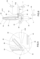
- Figure 1 shows a constructive and plant diagram of the device described above relating to the prior art, where it is possible to recognize the two pushers and the unthreading function with the two dedicated solenoid valves.
- figure 2 shows the time trend of the corresponding supply pressures p_1 (t) and p_3 (t) of the two solenoid valves.
- reference numeral 4 globally denotes a winding machine comprising a plurality of winding units 8.
- At least one winding unit 8 comprises a spool changing device 12, for changing spools 16 comprising yarn 20 wound on a tube 24 supported by a plate 26.
- the tube 24 extends along a vertical axis Y-Y, preferably perpendicular to the plate 26.
- thread or single thread or continuous thread refers to a single filament or continuous filament (for example in the case of silk, artificial or synthetic fibres) while the term yarn refers to a group of fibrils of varying lengths which are paralleled and joined together by twisting.
- thread or single thread or continuous thread refers to a single filament or continuous filament (for example in the case of silk, artificial or synthetic fibres) while the term yarn refers to a group of fibrils of varying lengths which are paralleled and joined together by twisting.
- one or the other term will be used indifferently, it being understood that the applications of the present invention are generic and all-encompassing, i.e., not limited to one or the other type/material.
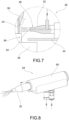
- the spool changing device 12 is provided with a tube locking pusher 28, provided with a locking stem 32 configured to pass from a retracted configuration, in which it does not interfere with the tube 24 of the spool 16, to an extracted configuration in which it obtains a constraint, preferably but not exclusively along a radial direction R-R, at a lower portion 36 of the tube 24 of the spool 16, facing said plate 26.
- the radial direction R-R is preferably perpendicular and incident with respect to the vertical axis Y-Y of the tube 24.
- the winding unit 8 further comprises a plate centring pusher 40 configured to influence, in an extracted configuration, the plate 26 abutting against a frame 44 of the spool changing device 12.
- the spool changing device 12 is provided with at least one nozzle 48 positioned and configured so as to direct, through at least one delivery hole 52, a jet of compressed air near said lower portion 36 of the tube 24 of the spool 16 influenced by the tube locking pusher 28, to prevent said tube locking pusher 28 from clamping a thread 56 of said yarn 20 wound on the tube 24 and positioned near said lower portion 36.
- said pushers slide axially inside relative cylinders 60.
- said nozzle 48 is integral with the frame 44 of the spool changing device 12. In such an embodiment, the nozzle 48 does not move with the passage of the tube locking pusher 28 from the retracted configuration to the extracted configuration.
- said nozzle 48 is integrally fixed to said locking stem 32.
- the nozzle 48 injects air at a delivery pressure p_2, for example by means of a second pneumatic solenoid valve 64, through said at least one delivery hole 52 obtained at the tip of the locking stem near the contact area (lower portion 36) during the stroke of the tube locking pusher 28 to move the thread 56 away and prevent the latter from being accidentally clamped by the locking stem 32.
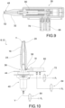
- the tube locking pusher 28 is configured as a pneumatic cylinder provided with a first chamber 68, placed under pressure p_1 by a first solenoid valve 72, and a second chamber 76, placed under pressure p_2 by the second solenoid valve 64. Both chambers 68,76 are in fluid communication with said locking stem 32 of the tube locking pusher 28.
- the second chamber 76 is hermetic and coaxial with respect to the first chamber 68.
- the second chamber 76 houses an elastic return element 80 of the locking stem 32 which elastically influences said locking stem 32 in said extracted position.
- the tube locking pusher 28 is provided at the tip with a cylindrical delivery hole 52 coaxial with the locking stem 32 and fluidly connected to the second chamber 76.
- the puff of air is integrated with the movement of the tube locking pusher 28 from both a constructive and a functional point of view, resulting in a greater compactness of the device and in a greater effectiveness of controlling the position of the thread 56, so that the latter is not accidentally clamped by the tube locking pusher 28.
- said at least one delivery hole 52 is arranged coaxial with respect to a main extension axis of the locking stem 32, arranged parallel to said radial direction R-R.
- the delivery hole 52 of the nozzle 48 has a diameter between 0.2 mm and 1.2 mm, preferably equal to 0.5 mm.
- the stroke of the tube locking pusher 28, equal to the distance between the retracted position and the extracted position, is between 5 mm and 15 mm, preferably 10 mm.
- the first solenoid valve 72 which controls the locking/unlocking of the tube locking pusher 28, is of the normally closed 3/2 type.
- the second solenoid valve 64 which controls the puff of air as well as the stroke of the locking stem 32, is of the normally closed 2/2 type.
- the winding unit 8 is provided with a spool unthreading jet fed by a third solenoid valve 84.
- supply pressures p_1 and p_2 can be distinct or equal to each other, and may or may not coincide with the line pressure of the plant. The same applies to the unthreading pressure p_3.
- said plate centring pusher 40 comprises a centring stem 88 provided with a through hole 92 configured so that, when it is extracted in the locking position of the plate 26, it allows a jet of unthreading air to flow therein, through said through hole 92.
- the jet of unthreading air exits through at least one circular sector-shaped slot 94 obtained on a sleeve 96 of the axial centring cylinder 98 which houses and guides said plate centring pusher 40.
- the plate centring pusher 40 is configured so that when the centring stem 88 retracts disengaging the plate 26, it blocks the unthreading flow by occluding the at least one slot 94 with the centring stem 88 and pressing against a hermetic closing element 100.
- the at least one slot 94 is kept open by the hermetic closing element 100, for example in the form of a rubber plug, coaxial to the centring stem 88, which abuts against a shoulder 104 of the axial centring cylinder 98, by virtue of the action of a spring 102, and thus creates a by-pass for the air.
- the hermetic closing element 100 for example in the form of a rubber plug, coaxial to the centring stem 88, which abuts against a shoulder 104 of the axial centring cylinder 98, by virtue of the action of a spring 102, and thus creates a by-pass for the air.
- the interval t_3-t_2 which determines the delay of extinguishing the puff of the tube locking pusher 28, cannot be chosen arbitrarily, having to reconcile on the one hand the need to reach the tube 24 with certainty and on the other to prevent the undesired triggering of unthreading. Therefore, the duration of such an interval t_3-t_2 is assumed to be 20 ms. By virtue of this configuration, it will therefore be possible to perform the unthreading separately and independently during the interval t_5-t_4 with one less solenoid valve, certain of the fact that upon the unthreading the air will only exit from the stem of the plate centring pusher 40, the puff being plugged by the contact with the tube 24 itself.
- a jet of compressed air is directed, through the delivery hole 52 of said nozzle 48 (whether it is separated or integrated in the tube locking pusher 28), near said lower portion 36 of the tube 24 of the spool 16, to prevent said tube locking pusher 28 from clamping a thread 56 of said yarn 20 wound on the tube 24.
- the operation continues with the step of switching the second solenoid valve 64 which allows the air to flow into the second chamber 76 and then through the delivery hole 52 at the tip of the tube locking pusher 28, with consequent deviation of the thread 56 free of yarn from the tube 24.
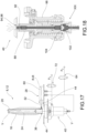
- the air flow rate of the puff is significantly lower than the inlet flow rate to the second chamber 76, the latter is gradually pressurized, progressively overcoming the elastic load of the elastic return element 80 compressed by the first chamber 68 and gradually releasing the tube locking pusher 28 towards the tube 24 ( figure 14 ).
- the plate centring pusher 40 exits, pressing the plate 26 against the frame 44 of the spool changing device 12 to lock it in position.
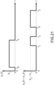
- the time interval t_2-t_1 is approximately 30 ms and coincides with the time necessary to achieve the nominal stroke of the tube locking stem 28.
- the switching off of the second solenoid valve 64 is delayed to an instant t_3 to ensure that the locking stem 32 of the tube locking pusher 28 actually reaches the tube 24 and that at the same time the thread 56 continues to be deflected precisely at upon the locking ( figure 16 ).
- the third solenoid valve 84 responsible for controlling the unthreading and independent of the other two solenoid valves 64,72, is switched after the instant t_3 and feeds the air jet inside the tube at a pressure p_3 for a predefined interval t_5-t_4.
- the interval t_3-t_2, which determines the delay of extinguishing the puff of the tube locking pusher 28, is chosen so as to reconcile, on the one hand, the need to reach the tube 24 with certainty and, on the other, the need to prevent the undesired triggering of unthreading.
- the duration of said interval t_3-t_2 is between 18 ms and 22 ms, and preferably is 20 ms.
- the present invention makes it possible to overcome the drawbacks mentioned of the prior art and to obtain considerable operational advantages.
- the sensorization on board the winding unit is reduced, as systems for controlling the presence of yarn at the end of the tube (e.g., photocells), with the consequent elimination of the risk of dirtying them.
- the fundamental concept underlying the invention relates to the juxtaposition of a pneumatic puff substantially simultaneous with the advancement stroke of the tube locking pusher.
- the adverb "substantially" is intended to protect also those embodiments in which the puff is not exactly simultaneous with the stroke of the tube locking pusher, but starts and ends respectively immediately before and/or immediately after the start and end of the stroke of the tube locking pusher.
- the impulsive action of the puff pushes the thread away during the stroke of the pusher, eliminating the undesired risk of clamping and allowing in particular the control of the thread only when really necessary, i.e., from the beginning of the stroke of the tube locking pusher until contact with the tube itself.
Landscapes
- Engineering & Computer Science (AREA)
- Textile Engineering (AREA)
- Replacing, Conveying, And Pick-Finding For Filamentary Materials (AREA)
- Winding Filamentary Materials (AREA)
- Replacement Of Web Rolls (AREA)
- Storage Of Web-Like Or Filamentary Materials (AREA)
Claims (14)
- Wickeleinheit (8), umfassend eine Spulenwechselvorrichtung (12) zum Wechseln von Spulen (16) mit Garn (20), das auf eine von einer Platte (26) getragene Hülse (24) gewickelt ist, wobei die Spulenwechselvorrichtung (12) versehen ist mit:- einem Hülsenverriegelungsdrücker bzw. -schieber (28), der mit einem Verriegelungsschaft (32) versehen ist, der konfiguriert ist, von einer eingefahrenen Konfiguration, in der er nicht mit der Hülse (24) der Spule (16) zusammentrifft, in eine ausgefahrene Konfiguration überzugehen, in der er an einem unteren Abschnitt (36) der Hülse (24) der Spule (16) der Platte (26) zugewandt eine Einschränkung erfährt,- einem Plattenzentrierdrücker bzw. -schieber (40), der konfiguriert ist, in einer ausgefahrenen Konfiguration die Platte (26) zu beeinflussen, die gegen einen Rahmen (44) der Spulenwechselvorrichtung (12) anliegt,dadurch gekennzeichnet, dass die Spulenwechselvorrichtung (12) mit zumindest einer Düse (48) versehen ist, die so positioniert und konfiguriert ist, dass sie durch zumindest ein Zufuhrloch (52) einen Druckluftstrahl nahe des unteren Abschnitts (36) der Hülse (24) der Spule (16) lenkt, der durch den Hülsenverriegelungsschieber (28) beeinflusst wird, um zu verhindern, dass der Hülsenverriegelungsschieber (28) einen Faden (56) des Garns (20) festklemmt, das auf die Hülse (24) gewickelt ist,wobei die Düse (48) integral an dem Verriegelungsschaft (32) fixiert bzw. befestigt ist.
- Wickeleinheit (8) nach Anspruch 1, wobei die Düse (48) Luft durch das zumindest eine Zufuhrloch (52) einbringt, das an der Spitze des Verriegelungsschafts (32) erhalten bzw. ausgebildet ist.
- Wickeleinheit (8) nach Anspruch 2, wobei das zumindest eine Zufuhrloch (52) koaxial in Bezug auf eine Haupterstreckungsachse des Verriegelungsschafts (32) angeordnet ist.
- Wickeleinheit (8) nach einem der Ansprüche 1 bis 3, wobei der Hülsenverriegelungsschieber (28) als ein pneumatischer Zylinder (60) konfiguriert ist, der mit einer ersten Kammer (68), die durch ein erstes Magnetventil (72) unter Druck p_1 gesetzt wird, und einer zweiten Kammer (76) versehen ist, die durch ein zweites Magnetventil (64) unter Druck p_2 gesetzt wird, wobei beide Kammern (68, 76) in Fluidverbindung mit dem Verriegelungsschaft (32) des Hülsenverriegelungsschiebers (28) sind.
- Wickeleinheit (8) nach Anspruch 4, wobei die zweite Kammer (76) hermetisch und koaxial in Bezug auf die erste Kammer (68) ist.
- Wickeleinheit (8) nach Anspruch 4 oder 5, wobei die zweite Kammer (76) ein elastisches Rückstellelement (80) des Verriegelungsschafts (32) aufnimmt, das den Verriegelungsschaft (32) in der ausgefahrenen Position elastisch beeinflusst.
- Wickeleinheit (8) nach Anspruch 4, 5 oder 6, wobei der Hülsenverriegelungsschieber (28) an der Spitze mit einem zylindrischen Zufuhrloch (52) versehen ist, das koaxial zu dem Verriegelungsschaft (32) ist und fluidisch mit der zweiten Kammer (76) verbunden ist.
- Wickeleinheit (8) nach einem der Ansprüche 4 bis 7, wobei die Wickeleinheit (8) mit einem Spulenausfädelstrahl versehen ist, der von einem dritten Magnetventil (84) gespeist wird.
- Wickeleinheit (8) nach einem der Ansprüche 4 bis 8, wobei der Plattenzentrierschieber (40) einen Zentrierschaft (88) umfasst, der mit einem inneren Durchgangsloch (92) versehen und so konfiguriert ist, dass er, wenn er in die Plattenverriegelungsposition ausgefahren ist, einen Strahl von Ausfädelluft durch das innere Durchgangsloch (92) in sich hindurchströmen lässt, wobei der Strahl von Ausfädelluft durch zumindest einen kreissektorförmigen Schlitz (94) austritt, der an einer Buchse (96) eines axialen Zentrierzylinders (98) erhalten bzw. ausgebildet ist, der den Plattenzentrierschieber (40) aufnimmt und führt.
- Wickeleinheit (8) nach Anspruch 9, wobei der Plattenzentrierschieber (40) so konfiguriert ist, dass er, wenn der Zentrierschaft (88) eingefahren ist und die Platte (26) außer Eingriff ist, den Ausfädelfluss blockiert, indem er den zumindest einen Schlitz (94) mit dem Zentrierschaft (88) verschließt und gegen ein hermetisches Verschlusselement (100) presst, wobei der zumindest eine Schlitz (94) durch das hermetische Verschlusselement (100), beispielsweise in der Form eines Gummidübels, offen gehalten wird, und zwar koaxial zu dem Zentrierschaft (88), und das an einer Schulter (104) des axialen Zentrierzylinders (98) anliegt.
- Steuerungs- bzw. Regelungsverfahren einer Wickelmaschine (4), umfassend die Schritte:- Bereitstellen einer Wickeleinheit (8) nach einem der Ansprüche 1 bis 10;- während des Durchgangs in der ausgefahrenen Konfiguration des Verriegelungsschafts (32) des Hülsenverriegelungsschiebers (28), Richten eines Druckluftstrahls durch das Zufuhrloch (52) der Düse (48) nahe des unteren Abschnitts (36) der Hülse (24) der Spule (16), um zu verhindern, dass der Hülsenverriegelungsschieber (28) einen Faden (56) des Garns (20), das auf die Hülse (24) gewickelt ist, festklemmt.
- Steuerungs- bzw. Regelungsverfahren nach Anspruch 11, umfassend die Schritte:- Bereitstellen einer Wickeleinheit (8) nach einem der Ansprüche 6 bis 7,- zu einem Anfangszeitpunkt t_0, wenn die Spule (16) die Platte (26) erreicht hat, Beaufschlagen der ersten Kammer (68) mit einem Druck p_1 und Einfahren des Hülsenverriegelungsschiebers (28) mit relativer Kompression des elastischen Rückstellelements (80), das auf den Verriegelungsschaft (32) einwirkt,- zu einem Zeitpunkt t_1, Umschalten des zweiten Magnetventils (64), das Luft in die zweite Kammer (76) und dann durch das Zufuhrloch (52) an der Spitze des Hülsenverriegelungsschiebers (28) strömen lässt, mit daraus folgender Abweichung des Fadens (56), der frei von Garn (20) ist, von der Hülse (24),- wobei, da während des Füllschritts die Luftdurchflussrate des Lufthauchs deutlich niedriger ist als die Einlassdurchflussrate zu der zweiten Kammer (76), letztere allmählich unter Druck gesetzt wird, wobei die elastische Last des elastischen Rückstellelements (80), das durch die erste Kammer (68) komprimiert wird und den Hülsenverriegelungsschieber (28) allmählich zu der Hülse (24) hin freigibt, schrittweise überwunden wird.
- Steuerungs- bzw. Regelungsverfahren nach Anspruch 12, wobei- zu einem Zeitpunkt t_2, die Position des ersten Magnetventils (72) umgeschaltet wird und das elastische Rückstellelement (80) die dadurch gespeicherte restliche elastische Last auf die Hülse (24) entlädt, was somit das Zurückhalten der Hülse (24) sicherstellt, wobei der Plattenzentrierschieber (40) austritt und die Platte (26) gegen den Rahmen (44) der Spulenwechselvorrichtung (12) presst, um sie an ihrem Platz zu verriegeln.
- Steuerungs- bzw. Regelungsverfahren nach Anspruch 12 oder 13, wobei das Ausschalten des zweiten Magnetventils (64) bis zu einem Zeitpunkt t_3 verzögert wird, um sicherzustellen, dass der Verriegelungsschaft (32) des Hülsenverriegelungsschiebers (28) tatsächlich die Hülse (24) erreicht und dass gleichzeitig der Faden (56) beim Verriegeln weiterhin präzise ausgelenkt wird, wobei ein drittes Magnetventil (84), das zum Steuern bzw. Regeln des Ausfädelns zuständig und unabhängig von den beiden anderen Magnetventilen (64, 72) ist, nach dem Zeitpunkt t_3 geschaltet wird und den Luftstrahl innerhalb der Hülse (24) mit einem Druck p_3 für ein vordefiniertes Intervall t_5-t_4 speist.
Applications Claiming Priority (1)
| Application Number | Priority Date | Filing Date | Title |
|---|---|---|---|
| IT102021000031307A IT202100031307A1 (it) | 2021-12-14 | 2021-12-14 | Unità di roccatura con spintore di bloccaggio tubetto e spintore di centratura piattello perfezionati e relativo metodo di controllo |
Publications (2)
| Publication Number | Publication Date |
|---|---|
| EP4197950A1 EP4197950A1 (de) | 2023-06-21 |
| EP4197950B1 true EP4197950B1 (de) | 2025-02-26 |
Family
ID=80448560
Family Applications (1)
| Application Number | Title | Priority Date | Filing Date |
|---|---|---|---|
| EP22202362.4A Active EP4197950B1 (de) | 2021-12-14 | 2022-10-19 | Wickeleinheit mit verbessertem rohrverriegelungsschieber und plattenzentrierschieber sowie zugehöriges steuerungsverfahren |
Country Status (3)
| Country | Link |
|---|---|
| EP (1) | EP4197950B1 (de) |
| CN (2) | CN116262578A (de) |
| IT (1) | IT202100031307A1 (de) |
Family Cites Families (4)
| Publication number | Priority date | Publication date | Assignee | Title |
|---|---|---|---|---|
| JPS6023260A (ja) * | 1983-07-19 | 1985-02-05 | Murata Mach Ltd | 糸端の口出し装置 |
| US5374000A (en) * | 1992-01-30 | 1994-12-20 | Murata Kikai Kabushiki Kaisha | Cop changing mechanism for a winding unit |
| US5590845A (en) * | 1993-09-24 | 1997-01-07 | Murata Kikai Kabushiki Kaisha | Yarn end finding apparatus and method |
| ITMI20070134A1 (it) * | 2007-01-29 | 2008-07-30 | Savio Macchine Tessili Spa | Stazione di roccatura automatica |
-
2021
- 2021-12-14 IT IT102021000031307A patent/IT202100031307A1/it unknown
-
2022
- 2022-10-19 EP EP22202362.4A patent/EP4197950B1/de active Active
- 2022-11-30 CN CN202211520012.8A patent/CN116262578A/zh active Pending
- 2022-11-30 CN CN202223216794.4U patent/CN218968482U/zh active Active
Also Published As
| Publication number | Publication date |
|---|---|
| IT202100031307A1 (it) | 2023-06-14 |
| CN116262578A (zh) | 2023-06-16 |
| EP4197950A1 (de) | 2023-06-21 |
| CN218968482U (zh) | 2023-05-05 |
Similar Documents
| Publication | Publication Date | Title |
|---|---|---|
| JPH026639A (ja) | オープンエンド紡績装置において糸継ぎを行う方法及び装置 | |
| JP2007513265A (ja) | 被覆弾性糸の製造及び供給スプールの自動交換に関する方法及び装置 | |
| CN101910486B (zh) | 由未加捻的纤维材料制造针织品的方法和编织机 | |
| CZ20022313A3 (cs) | Servisní zařízení k opětovnému zapřadení na pracovních místech dopřádacího stroje | |
| EP4197950A1 (de) | Wickeleinheit mit verbessertem rohrverriegelungsschieber und plattenzentrierschieber sowie zugehöriges steuerungsverfahren | |
| US3544018A (en) | Bobbin handling | |
| CN101910483A (zh) | 由未加捻的纤维材料制造针织品的方法和圆型编织机 | |
| EP0943714B1 (de) | Verfahren und Vorrichtung zum Verringern der Einführfadenlänge an Rundstrickmaschinen | |
| JPH03223073A (ja) | ワインダの巻成部における糸結合並びにコツプ交換を自動的に行うための装置 | |
| EP2230342A1 (de) | Verfahren und Speichervorrichtung zum Speichern von Schussfäden in einer Webmaschine | |
| EP1314673B1 (de) | Vorrichtung und Verfahren zum Entfernen von defekten Fädenteilen auf eine Lieferspule in einem Spulautomaten | |
| IT201900009687A1 (it) | Dispositivo e metodo per il controllo di un balloon durante la dipanatura di un filato da una spola | |
| US5072760A (en) | Device for drawing a yarn into a weft accumulator | |
| US6199598B1 (en) | Measuring feeding device with brake shoe clamp | |
| ITMI20070134A1 (it) | Stazione di roccatura automatica | |
| US5441087A (en) | Yarn storage and feed device utilizing correctional air jet nozzles | |
| US6591600B2 (en) | Rotor spinning machine | |
| EP1712509B1 (de) | Vorrichtung und Verfahren zum Handhaben und Kontrollieren eines Garnes eines Kreuzspulkopfes einer Kreuzspulmaschine während des Startens einer neuen Partie | |
| CS9004713A2 (en) | Weft feeder for jet looms | |
| CZ58394A3 (en) | Weft feeder for gripper shuttle and needle looms | |
| CZ87698A3 (cs) | Zařízení pro blokování útkové nitě během jejího odstřihování pro přiřazení k měřicímu podavači útku | |
| US5018557A (en) | Weft-switching system with telescoping nozzles | |
| US5170822A (en) | Yarn storage and feed device with axially adjustable yarn stopping element | |
| CN113355773A (zh) | 纺纱或绕线机的操作方法以及纺纱或绕线机 | |
| JP2019525017A (ja) | 帯状の繊維集合体を加工する方法ならびに粗紡機 |
Legal Events
| Date | Code | Title | Description |
|---|---|---|---|
| PUAI | Public reference made under article 153(3) epc to a published international application that has entered the european phase |
Free format text: ORIGINAL CODE: 0009012 |
|
| STAA | Information on the status of an ep patent application or granted ep patent |
Free format text: STATUS: THE APPLICATION HAS BEEN PUBLISHED |
|
| AK | Designated contracting states |
Kind code of ref document: A1 Designated state(s): AL AT BE BG CH CY CZ DE DK EE ES FI FR GB GR HR HU IE IS IT LI LT LU LV MC ME MK MT NL NO PL PT RO RS SE SI SK SM TR |
|
| P01 | Opt-out of the competence of the unified patent court (upc) registered |
Effective date: 20230628 |
|
| STAA | Information on the status of an ep patent application or granted ep patent |
Free format text: STATUS: REQUEST FOR EXAMINATION WAS MADE |
|
| 17P | Request for examination filed |
Effective date: 20231219 |
|
| RBV | Designated contracting states (corrected) |
Designated state(s): AL AT BE BG CH CY CZ DE DK EE ES FI FR GB GR HR HU IE IS IT LI LT LU LV MC ME MK MT NL NO PL PT RO RS SE SI SK SM TR |
|
| GRAP | Despatch of communication of intention to grant a patent |
Free format text: ORIGINAL CODE: EPIDOSNIGR1 |
|
| STAA | Information on the status of an ep patent application or granted ep patent |
Free format text: STATUS: GRANT OF PATENT IS INTENDED |
|
| GRAS | Grant fee paid |
Free format text: ORIGINAL CODE: EPIDOSNIGR3 |
|
| INTG | Intention to grant announced |
Effective date: 20241127 |
|
| GRAA | (expected) grant |
Free format text: ORIGINAL CODE: 0009210 |
|
| STAA | Information on the status of an ep patent application or granted ep patent |
Free format text: STATUS: THE PATENT HAS BEEN GRANTED |
|
| AK | Designated contracting states |
Kind code of ref document: B1 Designated state(s): AL AT BE BG CH CY CZ DE DK EE ES FI FR GB GR HR HU IE IS IT LI LT LU LV MC ME MK MT NL NO PL PT RO RS SE SI SK SM TR |
|
| REG | Reference to a national code |
Ref country code: GB Ref legal event code: FG4D |
|
| REG | Reference to a national code |
Ref country code: CH Ref legal event code: EP |
|
| REG | Reference to a national code |
Ref country code: DE Ref legal event code: R096 Ref document number: 602022011056 Country of ref document: DE |
|
| REG | Reference to a national code |
Ref country code: IE Ref legal event code: FG4D |
|
| REG | Reference to a national code |
Ref country code: NL Ref legal event code: MP Effective date: 20250226 |
|
| PG25 | Lapsed in a contracting state [announced via postgrant information from national office to epo] |
Ref country code: RS Free format text: LAPSE BECAUSE OF FAILURE TO SUBMIT A TRANSLATION OF THE DESCRIPTION OR TO PAY THE FEE WITHIN THE PRESCRIBED TIME-LIMIT Effective date: 20250526 |
|
| PG25 | Lapsed in a contracting state [announced via postgrant information from national office to epo] |
Ref country code: FI Free format text: LAPSE BECAUSE OF FAILURE TO SUBMIT A TRANSLATION OF THE DESCRIPTION OR TO PAY THE FEE WITHIN THE PRESCRIBED TIME-LIMIT Effective date: 20250226 |
|
| PG25 | Lapsed in a contracting state [announced via postgrant information from national office to epo] |
Ref country code: PL Free format text: LAPSE BECAUSE OF FAILURE TO SUBMIT A TRANSLATION OF THE DESCRIPTION OR TO PAY THE FEE WITHIN THE PRESCRIBED TIME-LIMIT Effective date: 20250226 |
|
| PG25 | Lapsed in a contracting state [announced via postgrant information from national office to epo] |
Ref country code: ES Free format text: LAPSE BECAUSE OF FAILURE TO SUBMIT A TRANSLATION OF THE DESCRIPTION OR TO PAY THE FEE WITHIN THE PRESCRIBED TIME-LIMIT Effective date: 20250226 |
|
| REG | Reference to a national code |
Ref country code: LT Ref legal event code: MG9D |
|
| PG25 | Lapsed in a contracting state [announced via postgrant information from national office to epo] |
Ref country code: NO Free format text: LAPSE BECAUSE OF FAILURE TO SUBMIT A TRANSLATION OF THE DESCRIPTION OR TO PAY THE FEE WITHIN THE PRESCRIBED TIME-LIMIT Effective date: 20250526 Ref country code: IS Free format text: LAPSE BECAUSE OF FAILURE TO SUBMIT A TRANSLATION OF THE DESCRIPTION OR TO PAY THE FEE WITHIN THE PRESCRIBED TIME-LIMIT Effective date: 20250626 |
|
| PG25 | Lapsed in a contracting state [announced via postgrant information from national office to epo] |
Ref country code: NL Free format text: LAPSE BECAUSE OF FAILURE TO SUBMIT A TRANSLATION OF THE DESCRIPTION OR TO PAY THE FEE WITHIN THE PRESCRIBED TIME-LIMIT Effective date: 20250226 |
|
| PG25 | Lapsed in a contracting state [announced via postgrant information from national office to epo] |
Ref country code: HR Free format text: LAPSE BECAUSE OF FAILURE TO SUBMIT A TRANSLATION OF THE DESCRIPTION OR TO PAY THE FEE WITHIN THE PRESCRIBED TIME-LIMIT Effective date: 20250226 |
|
| PG25 | Lapsed in a contracting state [announced via postgrant information from national office to epo] |
Ref country code: PT Free format text: LAPSE BECAUSE OF FAILURE TO SUBMIT A TRANSLATION OF THE DESCRIPTION OR TO PAY THE FEE WITHIN THE PRESCRIBED TIME-LIMIT Effective date: 20250626 Ref country code: LV Free format text: LAPSE BECAUSE OF FAILURE TO SUBMIT A TRANSLATION OF THE DESCRIPTION OR TO PAY THE FEE WITHIN THE PRESCRIBED TIME-LIMIT Effective date: 20250226 |
|
| PG25 | Lapsed in a contracting state [announced via postgrant information from national office to epo] |
Ref country code: GR Free format text: LAPSE BECAUSE OF FAILURE TO SUBMIT A TRANSLATION OF THE DESCRIPTION OR TO PAY THE FEE WITHIN THE PRESCRIBED TIME-LIMIT Effective date: 20250527 Ref country code: BG Free format text: LAPSE BECAUSE OF FAILURE TO SUBMIT A TRANSLATION OF THE DESCRIPTION OR TO PAY THE FEE WITHIN THE PRESCRIBED TIME-LIMIT Effective date: 20250226 |
|
| REG | Reference to a national code |
Ref country code: AT Ref legal event code: MK05 Ref document number: 1770480 Country of ref document: AT Kind code of ref document: T Effective date: 20250226 |
|
| PG25 | Lapsed in a contracting state [announced via postgrant information from national office to epo] |
Ref country code: SE Free format text: LAPSE BECAUSE OF FAILURE TO SUBMIT A TRANSLATION OF THE DESCRIPTION OR TO PAY THE FEE WITHIN THE PRESCRIBED TIME-LIMIT Effective date: 20250226 |
|
| PG25 | Lapsed in a contracting state [announced via postgrant information from national office to epo] |
Ref country code: SM Free format text: LAPSE BECAUSE OF FAILURE TO SUBMIT A TRANSLATION OF THE DESCRIPTION OR TO PAY THE FEE WITHIN THE PRESCRIBED TIME-LIMIT Effective date: 20250226 |
|
| PG25 | Lapsed in a contracting state [announced via postgrant information from national office to epo] |
Ref country code: DK Free format text: LAPSE BECAUSE OF FAILURE TO SUBMIT A TRANSLATION OF THE DESCRIPTION OR TO PAY THE FEE WITHIN THE PRESCRIBED TIME-LIMIT Effective date: 20250226 |
|
| PG25 | Lapsed in a contracting state [announced via postgrant information from national office to epo] |
Ref country code: AT Free format text: LAPSE BECAUSE OF FAILURE TO SUBMIT A TRANSLATION OF THE DESCRIPTION OR TO PAY THE FEE WITHIN THE PRESCRIBED TIME-LIMIT Effective date: 20250226 |
|
| PG25 | Lapsed in a contracting state [announced via postgrant information from national office to epo] |
Ref country code: EE Free format text: LAPSE BECAUSE OF FAILURE TO SUBMIT A TRANSLATION OF THE DESCRIPTION OR TO PAY THE FEE WITHIN THE PRESCRIBED TIME-LIMIT Effective date: 20250226 Ref country code: CZ Free format text: LAPSE BECAUSE OF FAILURE TO SUBMIT A TRANSLATION OF THE DESCRIPTION OR TO PAY THE FEE WITHIN THE PRESCRIBED TIME-LIMIT Effective date: 20250226 |
|
| PG25 | Lapsed in a contracting state [announced via postgrant information from national office to epo] |
Ref country code: RO Free format text: LAPSE BECAUSE OF FAILURE TO SUBMIT A TRANSLATION OF THE DESCRIPTION OR TO PAY THE FEE WITHIN THE PRESCRIBED TIME-LIMIT Effective date: 20250226 |
|
| PG25 | Lapsed in a contracting state [announced via postgrant information from national office to epo] |
Ref country code: SK Free format text: LAPSE BECAUSE OF FAILURE TO SUBMIT A TRANSLATION OF THE DESCRIPTION OR TO PAY THE FEE WITHIN THE PRESCRIBED TIME-LIMIT Effective date: 20250226 |
|
| REG | Reference to a national code |
Ref country code: DE Ref legal event code: R097 Ref document number: 602022011056 Country of ref document: DE |
|
| PLBE | No opposition filed within time limit |
Free format text: ORIGINAL CODE: 0009261 |
|
| STAA | Information on the status of an ep patent application or granted ep patent |
Free format text: STATUS: NO OPPOSITION FILED WITHIN TIME LIMIT |
|
| PGFP | Annual fee paid to national office [announced via postgrant information from national office to epo] |
Ref country code: DE Payment date: 20251027 Year of fee payment: 4 |
|
| PGFP | Annual fee paid to national office [announced via postgrant information from national office to epo] |
Ref country code: IT Payment date: 20251031 Year of fee payment: 4 |
|
| PGFP | Annual fee paid to national office [announced via postgrant information from national office to epo] |
Ref country code: TR Payment date: 20251006 Year of fee payment: 4 |
|
| 26N | No opposition filed |
Effective date: 20251127 |