EP4197943B1 - Procédé de manipulation de couches de boîtes vides et dispositif de manipulation de couches de boîtes vides - Google Patents
Procédé de manipulation de couches de boîtes vides et dispositif de manipulation de couches de boîtes vides Download PDFInfo
- Publication number
- EP4197943B1 EP4197943B1 EP22211340.9A EP22211340A EP4197943B1 EP 4197943 B1 EP4197943 B1 EP 4197943B1 EP 22211340 A EP22211340 A EP 22211340A EP 4197943 B1 EP4197943 B1 EP 4197943B1
- Authority
- EP
- European Patent Office
- Prior art keywords
- empty cans
- layer
- empty
- cans
- suctioned
- Prior art date
- Legal status (The legal status is an assumption and is not a legal conclusion. Google has not performed a legal analysis and makes no representation as to the accuracy of the status listed.)
- Active
Links
Images

Classifications
-
- B—PERFORMING OPERATIONS; TRANSPORTING
- B65—CONVEYING; PACKING; STORING; HANDLING THIN OR FILAMENTARY MATERIAL
- B65G—TRANSPORT OR STORAGE DEVICES, e.g. CONVEYORS FOR LOADING OR TIPPING, SHOP CONVEYOR SYSTEMS OR PNEUMATIC TUBE CONVEYORS
- B65G47/00—Article or material-handling devices associated with conveyors; Methods employing such devices
- B65G47/74—Feeding, transfer, or discharging devices of particular kinds or types
- B65G47/90—Devices for picking-up and depositing articles or materials
- B65G47/91—Devices for picking-up and depositing articles or materials incorporating pneumatic, e.g. suction, grippers
- B65G47/917—Devices for picking-up and depositing articles or materials incorporating pneumatic, e.g. suction, grippers control arrangements
-
- B—PERFORMING OPERATIONS; TRANSPORTING
- B07—SEPARATING SOLIDS FROM SOLIDS; SORTING
- B07C—POSTAL SORTING; SORTING INDIVIDUAL ARTICLES, OR BULK MATERIAL FIT TO BE SORTED PIECE-MEAL, e.g. BY PICKING
- B07C5/00—Sorting according to a characteristic or feature of the articles or material being sorted, e.g. by control effected by devices which detect or measure such characteristic or feature; Sorting by manually actuated devices, e.g. switches
- B07C5/34—Sorting according to other particular properties
-
- B—PERFORMING OPERATIONS; TRANSPORTING
- B65—CONVEYING; PACKING; STORING; HANDLING THIN OR FILAMENTARY MATERIAL
- B65G—TRANSPORT OR STORAGE DEVICES, e.g. CONVEYORS FOR LOADING OR TIPPING, SHOP CONVEYOR SYSTEMS OR PNEUMATIC TUBE CONVEYORS
- B65G43/00—Control devices, e.g. for safety, warning or fault-correcting
-
- G—PHYSICS
- G01—MEASURING; TESTING
- G01N—INVESTIGATING OR ANALYSING MATERIALS BY DETERMINING THEIR CHEMICAL OR PHYSICAL PROPERTIES
- G01N33/00—Investigating or analysing materials by specific methods not covered by groups G01N1/00 - G01N31/00
- G01N33/0078—Testing material properties on manufactured objects
- G01N33/0081—Containers; Packages; Bottles
Definitions
- the present invention relates to a method for handling layers of empty cans and a device for handling layers of empty cans.
- the present invention relates to a method and a device for removing defective empty cans before further processing, for example before filling and closing them.
- a method and a device for removing defective empty cans before further processing for example before filling and closing them.
- Such a method and such a device are used in particular in the beverage industry.
- the empty cans used for this purpose are provided as new container cans in pallet layers.
- the new container cans are in particular empty cans without a top lid.
- an intermediate layer made of a flat material for example a paper layer, a thin plastic layer, a cardboard intermediate layer or similar, can be arranged between the stacked empty can layers.
- the layers of empty cans are generally completely encompassed by a gripping device and pushed onto a transport device, via which the layer of empty cans is fed for further processing.
- a defect in a faulty empty can can be caused by a production error, damage during transport or similar factors.
- the defect can be in the form of bends, dents, kinks, cuts or similar on the empty cans. Since defective or faulty empty cans should preferably not be processed, as this would result in defective products, it is desirable to identify them in good time and to remove them from the processing before further processing.
- the patent specification EP 0 040 661 B1 refers to a method for automatically sorting out defective empty cans and to a corresponding device. These include a flange section inspection process and a print quality inspection process and are equipped with an empty can feed mechanism and/or empty can discharge mechanism to intermittently convey a continuously arriving group of empty cans to a predetermined position in an inspection station one at a time.
- the empty can positioned one at a time in the inspection station of the device is rotated by a rotating mechanism. During rotation, a change in a static magnetic field is detected by a magnetic head, whereby defects can be detected.
- the patent specification EP 0 055 296 B1 refers to a rotating light tester for inspecting empty cans.
- the empty cans are examined for various defects, whereby the empty cans are not damaged during the inspection. In this way, for example, cracks in the empty cans can be identified, which would lead to a leak in the filled empty cans.
- DE202017104004U1 discloses a method according to the preamble of claim 1 and a device according to the preamble of claim 9.
- the object of the invention is to eliminate the disadvantages of the known prior art and in particular to provide a simple method and a corresponding device which allows defective empty cans to be identified in a simple and time-saving manner and to be removed from the ongoing production before handling by subsequent processing devices.
- An empty can layer comprises a plurality of regularly arranged empty cans with openings on the top and side surfaces.
- the core of the invention relates to the dropping and disposal of defective empty cans from a layer of empty cans, so that only intact empty cans are fed for further processing, in particular filling, etc.
- Defective or faulty empty cans are understood to mean in particular those which are already bent or dented or which have other deformations. Cracks in the empty can material also represent a defect which would lead to faulty products. It is therefore also necessary to identify such faulty empty cans 24 and to remove them from the production process before further processing. In particular, the effect is exploited here that cracks in empty cans also lead to the faulty empty cans becoming deformed when a negative pressure increased to a limit is applied.
- the layers of empty cans are provided at a receiving location.
- several layers of empty cans stacked on top of each other on a pallet are provided at the receiving location.
- all empty cans in an empty can layer are sucked in and held in place by applying a negative pressure to the top openings of the empty cans.
- all empty cans in an empty can layer are sucked in and held in place by applying a negative pressure to the top openings of the empty cans at the same time.
- the suction vacuum is increased up to a predefined limit.
- the limit is formed by a vacuum at which the The compressive forces acting on the outer surfaces of the empty cans of intact empty cans are compensated by their inherent stability at least to the extent that the outer surfaces elastically return to their original contour after the negative pressure is removed or reduced.
- the limit value depends on the respective empty cans and is determined, for example, based on their volume, the empty can material, the wall thickness and possibly other parameters.
- empty cans In particular, mechanically intact and/or undeformed empty cans continue to be held under suction until the negative pressure limit is reached.
- faulty empty cans are plastically deformed before or when the limit is reached.
- faulty empty cans can implode before or when the limit is reached.
- One embodiment provides that the mechanically intact and/or undeformed empty cans held by suction are fed to a storage location and/or for further processing.
- the defective empty cans are removed from the production facility.
- Another embodiment provides that the empty can layer is sucked in with a first suction pressure and held in place by suction.
- the empty can layer held in place by suction is arranged above a collecting container.
- the suction negative pressure is then increased to the limit value, whereby faulty empty cans are released from the empty can layer and fall into the collecting container.
- the mechanically intact and/or undeformed empty cans, which are still held in place by suction, are then fed for further processing.
- An alternative embodiment provides that the empty can layer is sucked in and held in place by suction.
- the negative pressure can be set directly to the limit value during suction.
- the empty can layer held in place by suction is then lifted.
- the faulty empty cans remain at the receiving location and can be removed from the production process using suitable equipment, such as a sliding element or similar.
- a further embodiment provides that the layer of empty cans held by suction is guided over a rejection or collection area after the limit value has been set, which rejection or collection area is characterized by a lower height level, so that defective empty cans fall into the rejection or collection area and are thus removed from the production process.
- a detection system can be provided to detect intact empty can layers, i.e. empty can layers that only contain mechanically intact and/or undeformed empty cans.
- a control device detects the falling of defective empty cans due to the need for pressure adjustment. If a defective empty can comes loose, the suction pressure must be increased in order to continue to achieve the desired negative pressure for the entire empty can layer. If, however, an empty can layer does not contain any defective empty cans, such adjustment is not necessary.
- the control device can therefore control a faster transfer of the empty container layer to the storage location, since no detour via a sorting or collection area or no time delay in a sorting or collection area is necessary.
- a layer of empty cans recognized as intact is fed directly to the storage location and/or further processing without a detour via the sorting or collection area, or such an intact layer of empty cans is fed to the storage location and/or further processing without a time delay to remove faulty empty cans.
- a device for handling layers of empty cans which comprises a receiving station, a storage station, a layer gripper, a device for receiving and/or removing faulty empty cans and a control device.
- the layers of empty cans are provided at the receiving location.
- several layers of empty cans stacked on top of each other on a pallet are provided at a support location.
- the intact empty cans from the empty can layer are then transferred to a storage location for the empty cans, which storage location is formed by a removal transport device or to which storage location a removal transport device is assigned.
- the layer of empty cans is grasped by a layer gripper, which is equipped to grasp a complete layer of empty cans at the receiving location by suction, transport them to the storage location and release them there.
- the control device is used in particular to control the layer gripper and, if necessary, other machine components.
- the control device includes a program for controlling the layer gripper, which program provides at least the following process parameters.
- a layer of empty cans is detected at the receiving location by applying an initial negative pressure. This negative pressure is increased to a predefined limit. Mechanically intact and/or undeformed empty cans are then released at the deposit location.
- the device for receiving and/or removing faulty empty cans can comprise a sorting or collecting area.
- this sorting or collecting area is formed in the area of the receiving location.
- a further embodiment can provide that the sorting or collecting area is formed adjacent to the receiving location or that the sorting or collecting area is formed between the receiving location and the storage location.
- the separation or collection area can be arranged at a height level which is below a height level of the receiving area and/or below a height level of the storage area.
- the height of the stack changes when the stack is unstacking. Either the layer gripper must compensate for this height difference when picking up the empty can layer.
- an adjustment device for setting the height of the picking up position can be assigned to the picking up position, so that the topmost empty can layer to be picked up is always at the same height.
- An embodiment can accordingly provide that the receiving location at which the empty can layers are provided is designed to be height-adjustable.
- the receiving location can assume different height levels depending on the load on the pallet, so that the top empty can to be picked up is preferably always arranged at the same height level.
- the detection and sorting of faulty empty cans can be carried out in connection with the destacking of layers of empty cans arranged one above the other.
- a further embodiment may provide that the layers of empty cans are first unstacked and then grasped by suction to sort out the defective empty cans and handled according to the method described above.
- One embodiment provides that a layer of empty cans is sucked in and held in place by suction.
- the negative pressure can be set directly to the limit value.
- the layer of empty cans held in place by suction is then lifted.
- the faulty empty cans remain at the receiving location and can be removed from the production process using suitable equipment, such as a sliding element.
- the layer of empty cans, which only contains intact empty cans, is now transferred to the storage location and set down there.
- the receiving space and the storage space can coincide, for example, a sucked layer is lifted, the Empty cans that have fallen out are pushed out of the area using a slider or something similar and the layer is put back in place.
- the invention uses a travel-controlled suction plate gripper to lift the empty can layer, which is equipped with a suction surface for the empty cans of the empty can layer.
- the layer gripper has a flat elastic foam plate on its underside that is equipped with suction holes, for example an elastic suction foam or a rubber plate equipped with suction holes or the like.
- a receiving connection of the layer gripper to the empty cans is designed in such a way that the suction foam presses from above onto the edge of the top openings of the empty cans. This creates an airtight, flush pressure connection between the suction foam and the empty cans.
- the faulty empty can Depending on the degree of damage to the faulty empty can, it will begin to deform at a certain negative pressure level. If the damage is at its most severe, the defective empty can may even collapse or implode completely.
- an intact empty can can be charged with a significantly higher negative pressure, i.e. a significantly greater pressure difference compared to normal pressure.
- care must be taken to ensure that the physical break point characteristic of the respective empty can is not reached.
- the suction surface can also be formed by an elastic foam plate with suction holes that is adapted to the position of the empty cans to be detected and can be supplied with negative pressure.
- the foam plate is pressed from above onto the top openings of the empty cans and the negative pressure is applied.
- the layer gripper can also comprise a flat suction rubber plate or a plurality of suction cups arranged flatly and in an appropriate number and arrangement.
- the negative pressure level can be increased up to a predefined limit.
- the faulty empty cans deform and/or implode, which means that the system tightness required for suction is lost in the area of the upper opening.
- the faulty empty cans are therefore no longer held in place by suction, but fall downwards out of the empty can position due to gravity.
- a centering device around the stack can be advantageous.
- an additional, in particular free-standing, intermediate layer lifter can be provided at the receiving location, which in particular comprises a standing sliding plate on the intermediate layer gripper head and is intended to lift the respective intermediate layer after the lateral removal of faulty empty cans into a collecting container.
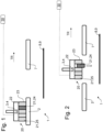
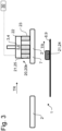
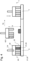
- the Figures 1 to 3 show a first embodiment of a method for handling layers of empty cans 20 using a schematically illustrated device 1 for handling layers of empty cans 20.
- Layers of empty cans 20 are provided at a receiving location 2.
- a single layer of empty cans 20 is provided.
- several layers of empty cans 20 stacked on top of each other on a pallet are provided at the receiving location 2.
- the empty can layer 20 comprises a plurality of regularly arranged empty cans 21 with top openings 22 and lateral surfaces 23.
- the empty can layer 20 includes defective or faulty empty cans 24.
- Defective or faulty empty cans 24 are understood to mean in particular those that are bent and/or dented or have other deformations. Cracks in the empty can material also represent a defect that would lead to faulty products. It is therefore also necessary to identify such faulty empty cans 24 and to remove them from the production process before further processing.
- a layer gripper 3 To detect the empty can layer 20, preferably all empty cans 21 of an empty can layer 20, i.e. both intact empty cans 25 and faulty empty cans 24, are detected by a layer gripper 3.
- the layer gripper 3 is particularly equipped to grasp the empty can layer 20 at the receiving location 2 by suction, to move it to the storage location 7 and to release it there.
- the empty cans 21 are sucked in and held in place by applying a negative pressure to the upper openings 22.
- the layer gripper 3 is designed as a travel-controlled suction plate gripper 4, which is equipped with a suction surface 5 for empty can layer 20.
- the layer gripper 3 has a flat elastic suction foam 6 on its underside. A receiving connection of the layer gripper 3 to the empty cans 21 is carried out in such a way that the suction foam 6 is applied from above to the edge of the upper openings 22. This creates an airtight, flush pressure connection between the suction surface 4 and the empty containers 21.
- the suction surface 5 can also be formed by an elastic foam plate equipped with suction holes, adapted to the respective empty can layer 20 to be grasped, to which negative pressure can be supplied.
- the foam plate is pressed from above onto the top openings of the empty cans and the negative pressure is applied.
- the layer gripper 3 can also comprise a flat suction rubber plate or a plurality of suction cups arranged flatly and in a corresponding number and arrangement.
- the layer gripper 3 now transfers the sucked-in empty can layer 20 to a storage location 7, wherein the layer gripper 3 guides the sucked-in empty can layer 20 over a sorting or collecting area 8.
- the suction negative pressure is increased up to a predefined limit value.
- the limit value depends on the respective empty cans 21 and is determined, for example, on the basis of their volume, the empty can material, the wall thickness and, if applicable, other parameters.
- the limit value is formed by a negative pressure at which the pressure forces of intact empty cans 25 acting on the outer surfaces 23 of the empty cans 21 are compensated by the inherent stability at least to such an extent that the outer surfaces 23 of the intact empty cans 25 elastically deform back into their original contour after the negative pressure is removed or reduced.
- faulty empty cans 24 are plastically deformed before or when the limit value is reached.
- faulty empty cans 24 can implode before or when the limit value is reached. This is caused by tensile forces inside the faulty empty cans 24, which tensile forces, when the negative pressure increases, cause the faulty empty cans 24 to plastically deform by mechanical contraction.
- the area of the top opening 22 of the faulty empty can 24 is usually deformed in such a way that it no longer closes off the suction surface 5. This opens the closed system and the faulty empty can 24 falls off the suction surface 5, while the intact empty cans 25 continue to be held by suction.
- an intact empty can 25 can be charged with a significantly higher negative pressure, i.e. a significantly greater pressure difference compared to normal pressure.
- care must be taken to ensure that the physical bending point characteristic of the respective empty cans 21 is not reached.
- the sorting or collection area 8 comprises, for example, a conveyor device 9 which removes the sorted out defective empty cans 24 in a transport direction TR from the sorting or collection area 8.
- the separation or collection area 8 can also be formed by a collection container 13 in which the defective empty cans 24 are collected (see Fig.5 ).
- the empty can layer 20 does not have to be raised significantly when it is collected at the receiving area 2 and transferred to the storage area 7.
- a substantially horizontal displacement movement in a Transport direction TR is sufficient, whereby a slight lifting of the detected empty can layer 20 can be advantageous to overcome the friction.
- the thus corrected empty can layer 20k which only includes intact empty cans 25, is now placed by the layer gripper 3 at the depositing location 3 and released ( Fig.3 ).
- the storage location 7 can be formed, for example, by a discharge transport device or the storage location 7 can be assigned a discharge transport device 7.
- the intact empty cans 25 can now be passed on for further processing (not shown).
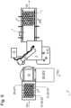
- the Fig.4 shows a second embodiment of a device 1 and a method for handling layers of empty cans 20.
- the detected layer of empty cans 20 is moved in the transport direction TR from the receiving location 2 to the depositing location 7, wherein the detected layer of empty cans 20 is raised to a height H, which height H corresponds to at least half a can height H21.
- the negative pressure is increased to the limit value so that defective empty cans 24 are released from the empty can layer 20.
- the defective empty cans 24 removed from the empty can layer 20 are removed, for example, by means of a side-acting pusher (not shown) or similar and transferred to a collecting container or similar.
- the corrected empty can layer 20k is arranged in the storage location 7 by lowering it and released by the layer gripper 3 for further processing.
- the Figures 5A to 5E show a third embodiment of a device 1 and a method for handling empty can layers 20.
- the receiving location 2 and the depositing location 7 are the same and form a combined receiving location/depositing location 15.
- This embodiment is particularly advantageous when the empty can layers 20 are already unstacked in individual layers and thus unstacking is not necessary. Otherwise, it can be advantageous to integrate the sorting out of faulty empty cans directly into the unstacking process.
- the empty can layer 20 is sucked in by the layer gripper 3 and held in place by suction ( Fig. 5A ). It is then intended that the empty can layer 20 is raised so that faulty empty cans 24, which become detached from the empty can layer 20 when the negative pressure increases, fall down ( Fig. 5B ). The fallen faulty empty cans 24 are removed from the combined receiving area/storage area 15 by a pusher or similar (not shown) ( Fig. 5C ) and the corrected empty can position 20 is now placed back in the combined receiving/storage location 15 ( Fig. 5D ). The intact empty cans 25 are removed in the transport direction TR after release by the layer gripper 3 and fed for further processing ( Fig. 5E ).
- the negative pressure can be set to the limit value directly when the empty can layer 20 is sucked in.
- the empty can layer 20 held in place by suction is now lifted.
- the faulty empty cans 24 remain directly at the combined receiving/depositing location 15 and can be removed from the production process by suitable devices, for example a sliding element.
- the schematic top view of the Fig.6 shows a fourth embodiment of a device 1 for handling layers of empty cans 20.
- the layers of empty cans 20 are provided in particular stacked on top of each other on pallets 26.
- the pallets 20 loaded with layers of empty cans 20 are fed in a first transport direction TR1.
- the empty pallet 26 is removed in a second transport direction TR2.
- the pallet 26 is arranged on a pallet rotating segment 10, by means of which the cleared pallet 26 can be transferred from a first working position AP1 forming the receiving location 2 to a second working position AP2, from which the empty pallet 26 can be transported away.
- the layer gripper 3 is arranged in particular on a rotatable robot arm 11, which can move the layer gripper 3 between the receiving location 2 and the storage location 7.
- a side channel compressor 12 is assigned to the layer gripper 3.
- a sorting or collecting area 8 with a collecting container 13 is provided between the receiving area 2 and the depositing area 7.
- the layer gripper 3 positions the sucked-in empty can layer 20 above the sorting or collecting area 8 and the negative pressure is increased to the limit value so that the defective empty cans 24 are released from the empty can layer 20 and fall into the collecting container 13.
- the corrected empty can layer 20k can now be removed from the storage location 7 in the transport direction TR and fed for further processing.
- the gaps formed by the sorted out faulty empty cans 24 within the corrected empty can layer 20k are marked with an L.
- the height of the stack changes as a result of the destacking.
- the layer gripper 3 must compensate for this height difference when grasping the empty can layer 20.
- an adjustment device (not shown) for adjusting a height level of the grasping position 2 can be assigned to the receiving station 2, so that the top empty can layer 20 to be grasped is always at the same height for grasping.
- a detection can also be provided with which intact empty can layers 20 are detected, ie empty can layers 20 which only include mechanically intact and/or undeformed empty cans 25.
- the control device 30 shown as an example prevents defective empty cans 24 from falling off due to a necessary pressure adjustment. If a defective empty can 24 comes off, the suction pressure must be increased in order to continue to maintain the desired negative pressure for to reach the entire empty can layer 20. However, if an empty can layer 20 does not contain any faulty empty cans 24, then such a readjustment is not necessary.
- the control device 30 can accordingly control a faster transfer of the empty container layer 20 to the storage location 7, since no detour via or no time delay in a sorting or collection area 8 is necessary.
- such an intact empty container layer 20 is fed directly to the storage location 7 and/or further processing without a detour via the sorting or collection area 8, or such an intact empty container layer 20 is fed to the storage location 7 and/or further processing without a time delay for the removal of faulty empty containers 24.
- a centering device around the stack may be advantageous (not shown).
- an additional, in particular free-standing intermediate layer lifter can be provided at the receiving location 2, which in particular comprises a standing sliding plate on the intermediate layer gripper head and is intended to lift the respective intermediate layer into a collecting container 13 after the lateral removal of faulty empty cans 24.
Landscapes
- Chemical & Material Sciences (AREA)
- Engineering & Computer Science (AREA)
- Health & Medical Sciences (AREA)
- Life Sciences & Earth Sciences (AREA)
- Analytical Chemistry (AREA)
- Food Science & Technology (AREA)
- Medicinal Chemistry (AREA)
- Physics & Mathematics (AREA)
- Mechanical Engineering (AREA)
- Biochemistry (AREA)
- General Health & Medical Sciences (AREA)
- General Physics & Mathematics (AREA)
- Immunology (AREA)
- Pathology (AREA)
- Stacking Of Articles And Auxiliary Devices (AREA)
- Specific Conveyance Elements (AREA)
Claims (13)
- Procédé de manipulation de couches de boîtes vides (20), lesquelles couches de boîtes vides (20) comprennent une pluralité de boîtes vides (21) qui sont disposées régulièrement et présentent des ouvertures supérieures (22) et des surfaces latérales (23) latérales,lesquelles couches de boîtes vides (20) sont fournies sur un emplacement de réception (2),dans lequel procédé toutes les boîtes vides (21) d'une couche de boîtes vides (20) sont aspirées et maintenues par aspiration en appliquant une pression négative aux ouvertures supérieures (22) des boîtes vides (21),dans lequel la pression négative d'aspiration est augmentée jusqu'à une valeur limite,caractérisé par le fait queà la valeur limite, les forces de pression de boîtes vides (21) intactes, qui agissent sur les surfaces latérales (23) des boîtes vides (21), sont compensées par la stabilité inhérente de celles-ci au moins dans la mesure où les surfaces latérales (23) se déforment élastiquement de manière à reprendre leur contour initial une fois la pression négative supprimée ou réduite.
- Procédé selon la revendication 1, dans lequel des boîtes vides (21) mécaniquement intactes et/ou non déformées continuent d'être maintenues par aspiration jusqu'à la valeur limite de la pression négative, tandis que des boîtes vides (21) défectueuse sont déformées plastiquement avant que ou lorsque la valeur limite soit/est atteinte.
- Procédé selon la revendication 1, dans lequel des boîtes vides (21) mécaniquement intactes et/ou non déformées continuent d'être maintenues par aspiration jusqu'à la valeur limite de la pression négative, tandis que des boîtes vides (21) défectueuse implosent avant que ou lorsque la valeur limite soit/est atteinte, et se détachent ainsi de la couche de boîtes vides (20).
- Procédé selon l'une quelconque des revendications précédentes, dans lequel les boîtes vides (21) mécaniquement intactes et/ou non déformées qui sont maintenues par aspiration sont amenées à un emplacement de dépôt (7) et/ou à un traitement ultérieur.
- Procédé selon l'une quelconque des revendications précédentes, dans lequel la couche de boîtes vides (20) est aspirée au moyen d'une première pression d'aspiration et est maintenue par aspiration, dans lequel la couche de boîtes vides (20) aspirée est disposée au-dessus d'un récipient collecteur (13), ce après quoi la pression négative d'aspiration est augmentée jusqu'à la valeur limite, dans lequel des boîtes vides (21) défectueuses se détachent de la couche de boîtes vides (20) et tombent dans le récipient collecteur (13), dans lequel les boîtes vides (21) mécaniquement intactes et/ou non déformées qui sont toujours maintenus par aspiration sont amenées au traitement ultérieur.
- Procédé selon l'une quelconque des revendications précédentes, dans lequel les couches de boîtes vides (20) maintenues par aspiration sont soulevées afin d'isoler les boîtes vides (21) défectueuses pour les retirer du processus de production ou
dans lequel la couche de boîtes vides (20) maintenue par aspiration est guidée sur une zone de tri ou de collecte (8) après avoir réglé la valeur limite, laquelle zone de tri ou de collecte (8) est caractérisée par un niveau de hauteur plus faible, dans lequel des boîtes vides (21) défectueuses tombent dans la zone de tri ou de collecte (8) et sont retirées du processus de production. - Procédé selon l'une quelconque des revendications 1 à 5, dans lequel, après avoir réglé la valeur limite, la couche de boîtes vides (20) maintenue par aspiration est guidée perpendiculairement à une direction de transport (TR) sur une zone de tri ou de collecte (8), laquelle zone de tri ou de collecte (8) est caractérisée par un niveau de hauteur plus faible, dans lequel des boîtes vides (21) défectueuses tombent dans la zone de tri ou de collecte (8), et dans lequel les boîtes vides (21) mécaniquement intactes et/ou non déformées qui sont maintenues par aspiration sont ensuite amenées dans la direction de transport (TR) au traitement ultérieur.
- Procédé selon l'une quelconque des revendications 6 ou 7, dans lequel on reconnaît qu'une couche de boîtes vides (20) maintenue par aspiration ne comprend que des boîtes vides (21) mécaniquement intactes et/ou non déformées,dans lequel une telle couche de boîtes vides (20) est amenée directement à l'emplacement de dépôt (7) et/ou au traitement ultérieur sans détour par la zone de tri ou de collecte (8), oudans lequel une telle couche de boîtes vides (20) est amenée à l'emplacement de dépôt (7) et/ou au traitement ultérieur sans aucun délai afin d'éliminer des boîtes vides (21) défectueuses.
- Dispositif (1) de manipulation de couches de boîtes vides (20), lesquelles couches de boîtes vides (20) comprennent une pluralité de boîtes vides (21) qui sont disposées régulièrement et présentent des ouvertures supérieures (22) et des surfaces latérales (23) latérales, le dispositif (1) comprenantun emplacement de réception (2) où sont fournies les couches de boîtes vides (20),un emplacement de dépôt (7) pour les boîtes vides (21), lequel emplacement de dépôt (7) est formé par un dispositif de transport qui évacue ou auquel emplacement de dépôt (7) est associé un dispositif de transport qui évacue,un dispositif de préhension de couche (3), lequel dispositif de préhension de couche (3) est équipé pour saisir par aspiration la couche de boîtes vides (20) à l'emplacement de réception (2), et lequel dispositif de préhension de couche (3) est équipé pour déplacer la couche de boîtes vides (20) vers l'emplacement de dépôt (7) et pour y libérer celle-ci,un dispositif de commande (30) pour commander le dispositif de préhension de couche (3) et d'autres composants de machine,caractérisé par le fait quele dispositif (1) comprend un dispositif de réception et/ou d'évacuation de boîtes vides défectueuses,dans lequel le dispositif de commande (30) comprend un programme pour commander le dispositif de préhension de couche (3), lequel programme prévoit les paramètres de procédé suivants:- saisir une couche de boîtes vides (20) à l'emplacement de réception (2) en appliquant une première pression négative;- augmenter la pression négative à une valeur limite prédéfinie; à laquelle valeur limite, les forces de pression de boîtes vides (21) intactes, qui agissent sur les surfaces latérales (23) des boîtes vides (21), sont compensées par la stabilité inhérente de celles-ci au moins dans la mesure où les surfaces latérales (23) se déforment élastiquement de manière à reprendre leur contour initial une fois la pression négative supprimée ou réduite;- libérer des boîtes vides (21) mécaniquement intactes et/ou non déformées, à l'emplacement de dépôt (7).
- Dispositif (1) selon la revendication 9, dans lequel le dispositif de réception et/ou d'évacuation de boîtes vides (21) défectueuses comprend une zone de tri ou de collecte (8), laquelle zone de tri ou de collecte (8) est réalisée dans la zone de l'emplacement de réception (2), oulaquelle zone de tri ou de collecte (8) est formée de manière voisine de l'emplacement de réception (2), oulaquelle zone de tri ou de collecte (8) est réalisée entre l'emplacement de réception (2) et l'emplacement de dépôt (7).
- Dispositif (1) selon la revendication 10, dans lequel la zone de tri ou de collecte (8) est disposée à un niveau de hauteur, lequel niveau de hauteur est disposé en dessous d'un niveau de hauteur de l'emplacement de réception (2) et/ou en dessous d'un niveau de hauteur de l'emplacement de dépôt (7).
- Dispositif (1) selon l'une quelconque des revendications 9 à 11, dans lequel à l'emplacement de réception (2) est associé un dispositif de réglage destiné à régler un niveau de hauteur de l'emplacement de réception (2).
- Dispositif (1) selon l'une quelconque des revendications 9 à 11, dans lequel le dispositif de préhension de couche (3) est une ventouse à déplacement commandé qui est équipée d'une surface d'aspiration pour les boîtes vides (21) de la couche de boîtes vides (20).
Priority Applications (1)
| Application Number | Priority Date | Filing Date | Title |
|---|---|---|---|
| SI202230043T SI4197943T1 (sl) | 2021-12-13 | 2022-12-05 | Postopek za ravnanje s plastmi praznih pločevink in naprava za ravnanje s plastmi praznih pločevink |
Applications Claiming Priority (1)
| Application Number | Priority Date | Filing Date | Title |
|---|---|---|---|
| DE102021132817.9A DE102021132817A1 (de) | 2021-12-13 | 2021-12-13 | Verfahren zum Handhaben von Leerdosenlagen und Vorrichtung zum Handhaben von Leerdosenlagen |
Publications (2)
| Publication Number | Publication Date |
|---|---|
| EP4197943A1 EP4197943A1 (fr) | 2023-06-21 |
| EP4197943B1 true EP4197943B1 (fr) | 2024-05-01 |
Family
ID=84767045
Family Applications (1)
| Application Number | Title | Priority Date | Filing Date |
|---|---|---|---|
| EP22211340.9A Active EP4197943B1 (fr) | 2021-12-13 | 2022-12-05 | Procédé de manipulation de couches de boîtes vides et dispositif de manipulation de couches de boîtes vides |
Country Status (4)
| Country | Link |
|---|---|
| EP (1) | EP4197943B1 (fr) |
| CN (1) | CN219078455U (fr) |
| DE (1) | DE102021132817A1 (fr) |
| SI (1) | SI4197943T1 (fr) |
Family Cites Families (9)
| Publication number | Priority date | Publication date | Assignee | Title |
|---|---|---|---|---|
| US3180499A (en) | 1962-04-12 | 1965-04-27 | Emhart Corp | Apparatus for removing articles from pallets |
| JPS5951875B2 (ja) | 1980-05-28 | 1984-12-17 | 東洋製罐株式会社 | 不良空缶自動弁別除去方法および装置 |
| JPS577545A (en) | 1980-06-18 | 1982-01-14 | Toyo Seikan Kaisha Ltd | Rotary type continuously optical inspecter for empty can |
| DE9002033U1 (de) | 1990-02-21 | 1990-04-26 | Krones Ag Hermann Kronseder Maschinenfabrik, 8402 Neutraubling | Sauggreifer für Gefäße |
| DE19505474C2 (de) * | 1995-02-17 | 1998-04-02 | Kronseder Maschf Krones | Verfahren und Vorrichtung zum Prüfen von Flaschen aus Kunststoff auf Kontaminationen |
| DE29707324U1 (de) * | 1997-04-23 | 1998-09-03 | Certus Maschinenbau GmbH, 86316 Friedberg | Vorrichtung zum Sammeln und Palettieren von Flaschen |
| JP3361463B2 (ja) | 1998-10-28 | 2003-01-07 | 株式会社キトー | 缶状物搬送クレーン |
| DE202017104004U1 (de) * | 2017-07-05 | 2018-10-09 | Autefa Solutions Germany Gmbh | Greifeinrichtung für Behälter |
| DE102018132242A1 (de) | 2018-12-14 | 2020-06-18 | Krones Aktiengesellschaft | Vorrichtung und Verfahren zur schichtweisen Handhabung von übereinander angeordneten Stückgutlagen |
-
2021
- 2021-12-13 DE DE102021132817.9A patent/DE102021132817A1/de active Pending
-
2022
- 2022-12-05 SI SI202230043T patent/SI4197943T1/sl unknown
- 2022-12-05 EP EP22211340.9A patent/EP4197943B1/fr active Active
- 2022-12-12 CN CN202223355799.5U patent/CN219078455U/zh active Active
Also Published As
| Publication number | Publication date |
|---|---|
| EP4197943A1 (fr) | 2023-06-21 |
| CN219078455U (zh) | 2023-05-26 |
| DE102021132817A1 (de) | 2023-06-15 |
| SI4197943T1 (sl) | 2024-08-30 |
Similar Documents
| Publication | Publication Date | Title |
|---|---|---|
| DE60013500T2 (de) | Automatisches Tafelzuführungssystem | |
| EP3085470B1 (fr) | Agencement mecanique pour le traitement de pieces en forme de plaque, notamment des toles et procede de manipulation d'un produit traitè sur un tel agencement mecanique | |
| EP3666696B1 (fr) | Dispositif et procede pour manipuler des couches de marchandises unitaires superposees | |
| EP1321397A1 (fr) | Procédé et dispositif pour désempiler des piles de découpés | |
| DE102020124432B4 (de) | Anleger einer Bogen be- oder verarbeitende Maschine sowie Verfahren zur Erfassung und/oder Korrektur von in Lage und/oder Abmessungen abweichenden Bogen in einem Anleger einer Bogen be- oder verarbeitende Maschine | |
| EP3837177A1 (fr) | Procédé de transfert et d'insertion d'articles dans des suremballages et dispositif de mise en oeuvre du procédé | |
| EP3247662B1 (fr) | Procédé et dispositif permettant de séparer des couches intermédiaires individuelles d'une pile de couches intermédiaires | |
| EP2243732B1 (fr) | Dispositif et procédé destinés à transférer des gerbes ou des couches d'articles dans une station de chargement | |
| DE102018105269A1 (de) | Verpackungsvorrichtung für Artikel und Verfahren zum Bereitstellen von flächigen Verpackungszuschnitten für Artikel | |
| DE102015119321B4 (de) | Vorrichtung zum Umgang mit Stückgütern mit einer hiermit in Zusammenhang stehenden Erzeugung und Handhabung von Zwischenlagen | |
| EP3348501A1 (fr) | Dispositif de préhension de produit | |
| DE102021131446B4 (de) | Stapelentpacker und Verfahren zu dessen Betrieb | |
| EP2923975A1 (fr) | Dispositif et procédé de dépalettisation pour le prélèvement de couches à partir de paquets d'une pile de marchandises | |
| EP4197943A1 (fr) | Procédé de manipulation de couches de boîtes vides et dispositif de manipulation de couches de boîtes vides | |
| EP4277868B1 (fr) | Procédé et système de séparation d'une pluralité d'ébauches d'emballage destinées à l'emballage d'articles | |
| EP2689645A1 (fr) | Procédé de fabrication d'un empilement de films et installation pour la fabrication d'un empilement de films | |
| EP3529183B1 (fr) | Procédé et dispositif pour la manutention de découpes planes d'une pile comprenant une pluralité de découpes planes | |
| DE10302953B4 (de) | Abladeanordnung und Verfahren zum sortierten Abladen von in Format und/oder Aufdruck unterschiedlicher Lagen aus blattförmigen Materialien | |
| DE102015200727B4 (de) | Vorrichtung und Verfahren zum Positionieren einzelner Zwischenlagen eines Zwischenlagenstapels auf zugeordneten Paletten | |
| DE19831068A1 (de) | Verfahren und Vorrichtung zum Einlegen von Produkten in eine Tiefzieh-Verpackungsmaschine | |
| DE102024128387A1 (de) | Vorrichtung und Verfahren zur Entnahme von Elektrodenblättern aus einem Magazin | |
| DE102023114672A1 (de) | Depalettierstation für Umverpackungen und Verpackungssystem | |
| DE102024116475A1 (de) | Verfahren zum Be- und Entladen eines Siegelwerkzeugs | |
| EP4215466A1 (fr) | Procédé de chargement mécanique ou de déchargement de matériau d'une machine de traitement et machine de traitement pour la mise en oeuvre du procédé | |
| EP4378864A1 (fr) | Procédé et dispositif de séparation d'un récipient ainsi que système de remplissage de récipients |
Legal Events
| Date | Code | Title | Description |
|---|---|---|---|
| PUAI | Public reference made under article 153(3) epc to a published international application that has entered the european phase |
Free format text: ORIGINAL CODE: 0009012 |
|
| STAA | Information on the status of an ep patent application or granted ep patent |
Free format text: STATUS: THE APPLICATION HAS BEEN PUBLISHED |
|
| AK | Designated contracting states |
Kind code of ref document: A1 Designated state(s): AL AT BE BG CH CY CZ DE DK EE ES FI FR GB GR HR HU IE IS IT LI LT LU LV MC ME MK MT NL NO PL PT RO RS SE SI SK SM TR |
|
| STAA | Information on the status of an ep patent application or granted ep patent |
Free format text: STATUS: REQUEST FOR EXAMINATION WAS MADE |
|
| 17P | Request for examination filed |
Effective date: 20230829 |
|
| RBV | Designated contracting states (corrected) |
Designated state(s): AL AT BE BG CH CY CZ DE DK EE ES FI FR GB GR HR HU IE IS IT LI LT LU LV MC ME MK MT NL NO PL PT RO RS SE SI SK SM TR |
|
| GRAP | Despatch of communication of intention to grant a patent |
Free format text: ORIGINAL CODE: EPIDOSNIGR1 |
|
| STAA | Information on the status of an ep patent application or granted ep patent |
Free format text: STATUS: GRANT OF PATENT IS INTENDED |
|
| RIC1 | Information provided on ipc code assigned before grant |
Ipc: B65G 47/91 20060101ALI20231103BHEP Ipc: B08B 9/46 20060101ALI20231103BHEP Ipc: B07C 5/34 20060101ALI20231103BHEP Ipc: B65G 43/00 20060101AFI20231103BHEP |
|
| INTG | Intention to grant announced |
Effective date: 20231204 |
|
| P01 | Opt-out of the competence of the unified patent court (upc) registered |
Effective date: 20240207 |
|
| GRAS | Grant fee paid |
Free format text: ORIGINAL CODE: EPIDOSNIGR3 |
|
| GRAA | (expected) grant |
Free format text: ORIGINAL CODE: 0009210 |
|
| STAA | Information on the status of an ep patent application or granted ep patent |
Free format text: STATUS: THE PATENT HAS BEEN GRANTED |
|
| AK | Designated contracting states |
Kind code of ref document: B1 Designated state(s): AL AT BE BG CH CY CZ DE DK EE ES FI FR GB GR HR HU IE IS IT LI LT LU LV MC ME MK MT NL NO PL PT RO RS SE SI SK SM TR |
|
| REG | Reference to a national code |
Ref country code: GB Ref legal event code: FG4D Free format text: NOT ENGLISH |
|
| REG | Reference to a national code |
Ref country code: CH Ref legal event code: EP |
|
| REG | Reference to a national code |
Ref country code: DE Ref legal event code: R096 Ref document number: 502022000841 Country of ref document: DE |
|
| REG | Reference to a national code |
Ref country code: IE Ref legal event code: FG4D Free format text: LANGUAGE OF EP DOCUMENT: GERMAN |
|
| REG | Reference to a national code |
Ref country code: LT Ref legal event code: MG9D |
|
| REG | Reference to a national code |
Ref country code: NL Ref legal event code: MP Effective date: 20240501 |
|
| PG25 | Lapsed in a contracting state [announced via postgrant information from national office to epo] |
Ref country code: IS Free format text: LAPSE BECAUSE OF FAILURE TO SUBMIT A TRANSLATION OF THE DESCRIPTION OR TO PAY THE FEE WITHIN THE PRESCRIBED TIME-LIMIT Effective date: 20240901 |
|
| PG25 | Lapsed in a contracting state [announced via postgrant information from national office to epo] |
Ref country code: BG Free format text: LAPSE BECAUSE OF FAILURE TO SUBMIT A TRANSLATION OF THE DESCRIPTION OR TO PAY THE FEE WITHIN THE PRESCRIBED TIME-LIMIT Effective date: 20240501 |
|
| PG25 | Lapsed in a contracting state [announced via postgrant information from national office to epo] |
Ref country code: FI Free format text: LAPSE BECAUSE OF FAILURE TO SUBMIT A TRANSLATION OF THE DESCRIPTION OR TO PAY THE FEE WITHIN THE PRESCRIBED TIME-LIMIT Effective date: 20240501 Ref country code: HR Free format text: LAPSE BECAUSE OF FAILURE TO SUBMIT A TRANSLATION OF THE DESCRIPTION OR TO PAY THE FEE WITHIN THE PRESCRIBED TIME-LIMIT Effective date: 20240501 |
|
| PG25 | Lapsed in a contracting state [announced via postgrant information from national office to epo] |
Ref country code: GR Free format text: LAPSE BECAUSE OF FAILURE TO SUBMIT A TRANSLATION OF THE DESCRIPTION OR TO PAY THE FEE WITHIN THE PRESCRIBED TIME-LIMIT Effective date: 20240802 |
|
| PG25 | Lapsed in a contracting state [announced via postgrant information from national office to epo] |
Ref country code: PT Free format text: LAPSE BECAUSE OF FAILURE TO SUBMIT A TRANSLATION OF THE DESCRIPTION OR TO PAY THE FEE WITHIN THE PRESCRIBED TIME-LIMIT Effective date: 20240902 |
|
| PG25 | Lapsed in a contracting state [announced via postgrant information from national office to epo] |
Ref country code: NL Free format text: LAPSE BECAUSE OF FAILURE TO SUBMIT A TRANSLATION OF THE DESCRIPTION OR TO PAY THE FEE WITHIN THE PRESCRIBED TIME-LIMIT Effective date: 20240501 |
|
| PG25 | Lapsed in a contracting state [announced via postgrant information from national office to epo] |
Ref country code: ES Free format text: LAPSE BECAUSE OF FAILURE TO SUBMIT A TRANSLATION OF THE DESCRIPTION OR TO PAY THE FEE WITHIN THE PRESCRIBED TIME-LIMIT Effective date: 20240501 |
|
| PG25 | Lapsed in a contracting state [announced via postgrant information from national office to epo] |
Ref country code: PL Free format text: LAPSE BECAUSE OF FAILURE TO SUBMIT A TRANSLATION OF THE DESCRIPTION OR TO PAY THE FEE WITHIN THE PRESCRIBED TIME-LIMIT Effective date: 20240501 |
|
| PG25 | Lapsed in a contracting state [announced via postgrant information from national office to epo] |
Ref country code: LV Free format text: LAPSE BECAUSE OF FAILURE TO SUBMIT A TRANSLATION OF THE DESCRIPTION OR TO PAY THE FEE WITHIN THE PRESCRIBED TIME-LIMIT Effective date: 20240501 |
|
| PG25 | Lapsed in a contracting state [announced via postgrant information from national office to epo] |
Ref country code: PT Free format text: LAPSE BECAUSE OF FAILURE TO SUBMIT A TRANSLATION OF THE DESCRIPTION OR TO PAY THE FEE WITHIN THE PRESCRIBED TIME-LIMIT Effective date: 20240902 Ref country code: PL Free format text: LAPSE BECAUSE OF FAILURE TO SUBMIT A TRANSLATION OF THE DESCRIPTION OR TO PAY THE FEE WITHIN THE PRESCRIBED TIME-LIMIT Effective date: 20240501 Ref country code: NO Free format text: LAPSE BECAUSE OF FAILURE TO SUBMIT A TRANSLATION OF THE DESCRIPTION OR TO PAY THE FEE WITHIN THE PRESCRIBED TIME-LIMIT Effective date: 20240801 Ref country code: NL Free format text: LAPSE BECAUSE OF FAILURE TO SUBMIT A TRANSLATION OF THE DESCRIPTION OR TO PAY THE FEE WITHIN THE PRESCRIBED TIME-LIMIT Effective date: 20240501 Ref country code: LV Free format text: LAPSE BECAUSE OF FAILURE TO SUBMIT A TRANSLATION OF THE DESCRIPTION OR TO PAY THE FEE WITHIN THE PRESCRIBED TIME-LIMIT Effective date: 20240501 Ref country code: IS Free format text: LAPSE BECAUSE OF FAILURE TO SUBMIT A TRANSLATION OF THE DESCRIPTION OR TO PAY THE FEE WITHIN THE PRESCRIBED TIME-LIMIT Effective date: 20240901 Ref country code: HR Free format text: LAPSE BECAUSE OF FAILURE TO SUBMIT A TRANSLATION OF THE DESCRIPTION OR TO PAY THE FEE WITHIN THE PRESCRIBED TIME-LIMIT Effective date: 20240501 Ref country code: GR Free format text: LAPSE BECAUSE OF FAILURE TO SUBMIT A TRANSLATION OF THE DESCRIPTION OR TO PAY THE FEE WITHIN THE PRESCRIBED TIME-LIMIT Effective date: 20240802 Ref country code: FI Free format text: LAPSE BECAUSE OF FAILURE TO SUBMIT A TRANSLATION OF THE DESCRIPTION OR TO PAY THE FEE WITHIN THE PRESCRIBED TIME-LIMIT Effective date: 20240501 Ref country code: ES Free format text: LAPSE BECAUSE OF FAILURE TO SUBMIT A TRANSLATION OF THE DESCRIPTION OR TO PAY THE FEE WITHIN THE PRESCRIBED TIME-LIMIT Effective date: 20240501 Ref country code: BG Free format text: LAPSE BECAUSE OF FAILURE TO SUBMIT A TRANSLATION OF THE DESCRIPTION OR TO PAY THE FEE WITHIN THE PRESCRIBED TIME-LIMIT Effective date: 20240501 Ref country code: RS Free format text: LAPSE BECAUSE OF FAILURE TO SUBMIT A TRANSLATION OF THE DESCRIPTION OR TO PAY THE FEE WITHIN THE PRESCRIBED TIME-LIMIT Effective date: 20240801 |
|
| REG | Reference to a national code |
Ref country code: DE Ref legal event code: R082 Ref document number: 502022000841 Country of ref document: DE Representative=s name: BENNINGER, JOHANNES, DIPL.-ING., DE |
|
| PG25 | Lapsed in a contracting state [announced via postgrant information from national office to epo] |
Ref country code: DK Free format text: LAPSE BECAUSE OF FAILURE TO SUBMIT A TRANSLATION OF THE DESCRIPTION OR TO PAY THE FEE WITHIN THE PRESCRIBED TIME-LIMIT Effective date: 20240501 |
|
| PG25 | Lapsed in a contracting state [announced via postgrant information from national office to epo] |
Ref country code: EE Free format text: LAPSE BECAUSE OF FAILURE TO SUBMIT A TRANSLATION OF THE DESCRIPTION OR TO PAY THE FEE WITHIN THE PRESCRIBED TIME-LIMIT Effective date: 20240501 |
|
| PG25 | Lapsed in a contracting state [announced via postgrant information from national office to epo] |
Ref country code: CZ Free format text: LAPSE BECAUSE OF FAILURE TO SUBMIT A TRANSLATION OF THE DESCRIPTION OR TO PAY THE FEE WITHIN THE PRESCRIBED TIME-LIMIT Effective date: 20240501 |
|
| PG25 | Lapsed in a contracting state [announced via postgrant information from national office to epo] |
Ref country code: RO Free format text: LAPSE BECAUSE OF FAILURE TO SUBMIT A TRANSLATION OF THE DESCRIPTION OR TO PAY THE FEE WITHIN THE PRESCRIBED TIME-LIMIT Effective date: 20240501 Ref country code: SK Free format text: LAPSE BECAUSE OF FAILURE TO SUBMIT A TRANSLATION OF THE DESCRIPTION OR TO PAY THE FEE WITHIN THE PRESCRIBED TIME-LIMIT Effective date: 20240501 |
|
| PG25 | Lapsed in a contracting state [announced via postgrant information from national office to epo] |
Ref country code: SM Free format text: LAPSE BECAUSE OF FAILURE TO SUBMIT A TRANSLATION OF THE DESCRIPTION OR TO PAY THE FEE WITHIN THE PRESCRIBED TIME-LIMIT Effective date: 20240501 |
|
| PG25 | Lapsed in a contracting state [announced via postgrant information from national office to epo] |
Ref country code: SM Free format text: LAPSE BECAUSE OF FAILURE TO SUBMIT A TRANSLATION OF THE DESCRIPTION OR TO PAY THE FEE WITHIN THE PRESCRIBED TIME-LIMIT Effective date: 20240501 Ref country code: SK Free format text: LAPSE BECAUSE OF FAILURE TO SUBMIT A TRANSLATION OF THE DESCRIPTION OR TO PAY THE FEE WITHIN THE PRESCRIBED TIME-LIMIT Effective date: 20240501 Ref country code: RO Free format text: LAPSE BECAUSE OF FAILURE TO SUBMIT A TRANSLATION OF THE DESCRIPTION OR TO PAY THE FEE WITHIN THE PRESCRIBED TIME-LIMIT Effective date: 20240501 Ref country code: EE Free format text: LAPSE BECAUSE OF FAILURE TO SUBMIT A TRANSLATION OF THE DESCRIPTION OR TO PAY THE FEE WITHIN THE PRESCRIBED TIME-LIMIT Effective date: 20240501 Ref country code: DK Free format text: LAPSE BECAUSE OF FAILURE TO SUBMIT A TRANSLATION OF THE DESCRIPTION OR TO PAY THE FEE WITHIN THE PRESCRIBED TIME-LIMIT Effective date: 20240501 Ref country code: CZ Free format text: LAPSE BECAUSE OF FAILURE TO SUBMIT A TRANSLATION OF THE DESCRIPTION OR TO PAY THE FEE WITHIN THE PRESCRIBED TIME-LIMIT Effective date: 20240501 |
|
| REG | Reference to a national code |
Ref country code: DE Ref legal event code: R097 Ref document number: 502022000841 Country of ref document: DE |
|
| PLBE | No opposition filed within time limit |
Free format text: ORIGINAL CODE: 0009261 |
|
| STAA | Information on the status of an ep patent application or granted ep patent |
Free format text: STATUS: NO OPPOSITION FILED WITHIN TIME LIMIT |
|
| 26N | No opposition filed |
Effective date: 20250204 |
|
| PG25 | Lapsed in a contracting state [announced via postgrant information from national office to epo] |
Ref country code: MC Free format text: LAPSE BECAUSE OF FAILURE TO SUBMIT A TRANSLATION OF THE DESCRIPTION OR TO PAY THE FEE WITHIN THE PRESCRIBED TIME-LIMIT Effective date: 20240501 |
|
| PG25 | Lapsed in a contracting state [announced via postgrant information from national office to epo] |
Ref country code: LU Free format text: LAPSE BECAUSE OF NON-PAYMENT OF DUE FEES Effective date: 20241205 |
|
| PG25 | Lapsed in a contracting state [announced via postgrant information from national office to epo] |
Ref country code: SE Free format text: LAPSE BECAUSE OF FAILURE TO SUBMIT A TRANSLATION OF THE DESCRIPTION OR TO PAY THE FEE WITHIN THE PRESCRIBED TIME-LIMIT Effective date: 20240501 |
|
| REG | Reference to a national code |
Ref country code: BE Ref legal event code: MM Effective date: 20241231 |
|
| PG25 | Lapsed in a contracting state [announced via postgrant information from national office to epo] |
Ref country code: BE Free format text: LAPSE BECAUSE OF NON-PAYMENT OF DUE FEES Effective date: 20241231 |
|
| PG25 | Lapsed in a contracting state [announced via postgrant information from national office to epo] |
Ref country code: IE Free format text: LAPSE BECAUSE OF NON-PAYMENT OF DUE FEES Effective date: 20241205 |
|
| PGFP | Annual fee paid to national office [announced via postgrant information from national office to epo] |
Ref country code: DE Payment date: 20251104 Year of fee payment: 4 |
|
| PGFP | Annual fee paid to national office [announced via postgrant information from national office to epo] |
Ref country code: AT Payment date: 20260113 Year of fee payment: 4 |
|
| PGFP | Annual fee paid to national office [announced via postgrant information from national office to epo] |
Ref country code: FR Payment date: 20251110 Year of fee payment: 4 |
|
| PGFP | Annual fee paid to national office [announced via postgrant information from national office to epo] |
Ref country code: SI Payment date: 20251113 Year of fee payment: 4 |
|
| PG25 | Lapsed in a contracting state [announced via postgrant information from national office to epo] |
Ref country code: CY Free format text: LAPSE BECAUSE OF FAILURE TO SUBMIT A TRANSLATION OF THE DESCRIPTION OR TO PAY THE FEE WITHIN THE PRESCRIBED TIME-LIMIT; INVALID AB INITIO Effective date: 20221205 |
|
| PGFP | Annual fee paid to national office [announced via postgrant information from national office to epo] |
Ref country code: IT Payment date: 20251231 Year of fee payment: 4 |
|
| PG25 | Lapsed in a contracting state [announced via postgrant information from national office to epo] |
Ref country code: TR Free format text: LAPSE BECAUSE OF FAILURE TO SUBMIT A TRANSLATION OF THE DESCRIPTION OR TO PAY THE FEE WITHIN THE PRESCRIBED TIME-LIMIT Effective date: 20240501 |
|
| PG25 | Lapsed in a contracting state [announced via postgrant information from national office to epo] |
Ref country code: HU Free format text: LAPSE BECAUSE OF FAILURE TO SUBMIT A TRANSLATION OF THE DESCRIPTION OR TO PAY THE FEE WITHIN THE PRESCRIBED TIME-LIMIT; INVALID AB INITIO Effective date: 20221205 |
|
| PG25 | Lapsed in a contracting state [announced via postgrant information from national office to epo] |
Ref country code: LT Free format text: LAPSE BECAUSE OF FAILURE TO SUBMIT A TRANSLATION OF THE DESCRIPTION OR TO PAY THE FEE WITHIN THE PRESCRIBED TIME-LIMIT Effective date: 20240501 |
|
| PG25 | Lapsed in a contracting state [announced via postgrant information from national office to epo] |
Ref country code: ME Free format text: LAPSE BECAUSE OF FAILURE TO SUBMIT A TRANSLATION OF THE DESCRIPTION OR TO PAY THE FEE WITHIN THE PRESCRIBED TIME-LIMIT Effective date: 20240501 |
|
| REG | Reference to a national code |
Ref country code: CH Ref legal event code: H13 Free format text: ST27 STATUS EVENT CODE: U-0-0-H10-H13 (AS PROVIDED BY THE NATIONAL OFFICE) Effective date: 20260723 |