EP4197861A1 - Verfahren zur befestigung eines emblems an einer abdeckung eines kraftfahrzeuglenkrads - Google Patents
Verfahren zur befestigung eines emblems an einer abdeckung eines kraftfahrzeuglenkrads Download PDFInfo
- Publication number
- EP4197861A1 EP4197861A1 EP22211433.2A EP22211433A EP4197861A1 EP 4197861 A1 EP4197861 A1 EP 4197861A1 EP 22211433 A EP22211433 A EP 22211433A EP 4197861 A1 EP4197861 A1 EP 4197861A1
- Authority
- EP
- European Patent Office
- Prior art keywords
- emblem
- glue
- cover
- bead
- process according
- Prior art date
- Legal status (The legal status is an assumption and is not a legal conclusion. Google has not performed a legal analysis and makes no representation as to the accuracy of the status listed.)
- Pending
Links
- 238000000034 method Methods 0.000 title claims abstract description 43
- 239000003292 glue Substances 0.000 claims abstract description 109
- 239000011324 bead Substances 0.000 claims abstract description 54
- 238000005304 joining Methods 0.000 claims abstract description 6
- 238000000151 deposition Methods 0.000 claims abstract description 5
- 238000003825 pressing Methods 0.000 claims abstract description 5
- 229920002397 thermoplastic olefin Polymers 0.000 claims description 15
- 239000000463 material Substances 0.000 claims description 13
- 238000004026 adhesive bonding Methods 0.000 claims description 12
- 239000004411 aluminium Substances 0.000 claims description 12
- XAGFODPZIPBFFR-UHFFFAOYSA-N aluminium Chemical compound [Al] XAGFODPZIPBFFR-UHFFFAOYSA-N 0.000 claims description 12
- 229910052782 aluminium Inorganic materials 0.000 claims description 12
- 239000000203 mixture Substances 0.000 claims description 12
- 238000004140 cleaning Methods 0.000 claims description 8
- 229920000515 polycarbonate Polymers 0.000 claims description 7
- 239000004417 polycarbonate Substances 0.000 claims description 7
- 239000004676 acrylonitrile butadiene styrene Substances 0.000 claims description 6
- 238000002203 pretreatment Methods 0.000 claims description 6
- 229920002725 thermoplastic elastomer Polymers 0.000 claims description 6
- LFQSCWFLJHTTHZ-UHFFFAOYSA-N Ethanol Chemical compound CCO LFQSCWFLJHTTHZ-UHFFFAOYSA-N 0.000 claims description 4
- 239000004721 Polyphenylene oxide Substances 0.000 claims description 4
- 238000009832 plasma treatment Methods 0.000 claims description 4
- 229920000570 polyether Polymers 0.000 claims description 4
- 239000002904 solvent Substances 0.000 claims description 4
- 238000011282 treatment Methods 0.000 claims description 4
- RYGMFSIKBFXOCR-UHFFFAOYSA-N Copper Chemical compound [Cu] RYGMFSIKBFXOCR-UHFFFAOYSA-N 0.000 claims description 3
- 239000004952 Polyamide Substances 0.000 claims description 3
- 239000004793 Polystyrene Substances 0.000 claims description 3
- NIXOWILDQLNWCW-UHFFFAOYSA-N acrylic acid group Chemical group C(C=C)(=O)O NIXOWILDQLNWCW-UHFFFAOYSA-N 0.000 claims description 3
- XECAHXYUAAWDEL-UHFFFAOYSA-N acrylonitrile butadiene styrene Chemical compound C=CC=C.C=CC#N.C=CC1=CC=CC=C1 XECAHXYUAAWDEL-UHFFFAOYSA-N 0.000 claims description 3
- 229920000122 acrylonitrile butadiene styrene Polymers 0.000 claims description 3
- 229920001577 copolymer Polymers 0.000 claims description 3
- 239000010949 copper Substances 0.000 claims description 3
- 229910052802 copper Inorganic materials 0.000 claims description 3
- 229920006335 epoxy glue Polymers 0.000 claims description 3
- 229920002647 polyamide Polymers 0.000 claims description 3
- 229920002223 polystyrene Polymers 0.000 claims description 3
- 230000037452 priming Effects 0.000 claims description 3
- 239000003707 silyl modified polymer Substances 0.000 claims description 3
- 230000001066 destructive effect Effects 0.000 description 13
- 229920003023 plastic Polymers 0.000 description 9
- 239000004033 plastic Substances 0.000 description 9
- 238000004519 manufacturing process Methods 0.000 description 7
- 239000000853 adhesive Substances 0.000 description 2
- 230000001070 adhesive effect Effects 0.000 description 2
- 230000008021 deposition Effects 0.000 description 2
- 230000000670 limiting effect Effects 0.000 description 2
- 238000005259 measurement Methods 0.000 description 2
- 238000002844 melting Methods 0.000 description 2
- 230000008018 melting Effects 0.000 description 2
- 238000005457 optimization Methods 0.000 description 2
- 239000003973 paint Substances 0.000 description 2
- 238000000926 separation method Methods 0.000 description 2
- 206010042674 Swelling Diseases 0.000 description 1
- 229920006895 TPC ET Polymers 0.000 description 1
- 229920006417 TPC-ET Polymers 0.000 description 1
- 208000027418 Wounds and injury Diseases 0.000 description 1
- 230000004913 activation Effects 0.000 description 1
- 230000006835 compression Effects 0.000 description 1
- 238000007906 compression Methods 0.000 description 1
- 230000006378 damage Effects 0.000 description 1
- 238000005034 decoration Methods 0.000 description 1
- 238000009826 distribution Methods 0.000 description 1
- 150000002334 glycols Chemical class 0.000 description 1
- 239000012535 impurity Substances 0.000 description 1
- 208000014674 injury Diseases 0.000 description 1
- 230000002427 irreversible effect Effects 0.000 description 1
- 230000003287 optical effect Effects 0.000 description 1
- 230000036961 partial effect Effects 0.000 description 1
- -1 polybutylene terephthalate Polymers 0.000 description 1
- 229920001707 polybutylene terephthalate Polymers 0.000 description 1
- 229920000728 polyester Polymers 0.000 description 1
- 230000001681 protective effect Effects 0.000 description 1
- 230000003068 static effect Effects 0.000 description 1
- 239000000126 substance Substances 0.000 description 1
- 230000008961 swelling Effects 0.000 description 1
- 230000001360 synchronised effect Effects 0.000 description 1
- 238000009864 tensile test Methods 0.000 description 1
- 238000002604 ultrasonography Methods 0.000 description 1
Images


Classifications
-
- B—PERFORMING OPERATIONS; TRANSPORTING
- B60—VEHICLES IN GENERAL
- B60R—VEHICLES, VEHICLE FITTINGS, OR VEHICLE PARTS, NOT OTHERWISE PROVIDED FOR
- B60R13/00—Elements for body-finishing, identifying, or decorating; Arrangements or adaptations for advertising purposes
- B60R13/005—Manufacturers' emblems, name plates, bonnet ornaments, mascots or the like; Mounting means therefor
-
- B—PERFORMING OPERATIONS; TRANSPORTING
- B60—VEHICLES IN GENERAL
- B60R—VEHICLES, VEHICLE FITTINGS, OR VEHICLE PARTS, NOT OTHERWISE PROVIDED FOR
- B60R21/00—Arrangements or fittings on vehicles for protecting or preventing injuries to occupants or pedestrians in case of accidents or other traffic risks
- B60R21/02—Occupant safety arrangements or fittings, e.g. crash pads
- B60R21/16—Inflatable occupant restraints or confinements designed to inflate upon impact or impending impact, e.g. air bags
- B60R21/20—Arrangements for storing inflatable members in their non-use or deflated condition; Arrangement or mounting of air bag modules or components
- B60R21/215—Arrangements for storing inflatable members in their non-use or deflated condition; Arrangement or mounting of air bag modules or components characterised by the covers for the inflatable member
- B60R21/2165—Arrangements for storing inflatable members in their non-use or deflated condition; Arrangement or mounting of air bag modules or components characterised by the covers for the inflatable member characterised by a tear line for defining a deployment opening
- B60R21/21656—Steering wheel covers or similar cup-shaped covers
-
- B—PERFORMING OPERATIONS; TRANSPORTING
- B60—VEHICLES IN GENERAL
- B60R—VEHICLES, VEHICLE FITTINGS, OR VEHICLE PARTS, NOT OTHERWISE PROVIDED FOR
- B60R21/00—Arrangements or fittings on vehicles for protecting or preventing injuries to occupants or pedestrians in case of accidents or other traffic risks
- B60R21/02—Occupant safety arrangements or fittings, e.g. crash pads
- B60R21/16—Inflatable occupant restraints or confinements designed to inflate upon impact or impending impact, e.g. air bags
- B60R21/20—Arrangements for storing inflatable members in their non-use or deflated condition; Arrangement or mounting of air bag modules or components
- B60R21/215—Arrangements for storing inflatable members in their non-use or deflated condition; Arrangement or mounting of air bag modules or components characterised by the covers for the inflatable member
- B60R2021/21543—Arrangements for storing inflatable members in their non-use or deflated condition; Arrangement or mounting of air bag modules or components characterised by the covers for the inflatable member with emblems
Definitions
- the present invention relates in general to the automotive sector.
- the present invention relates to the sector of the production of covers for motor-vehicle steering wheels.
- the present invention relates to a process for fixing an emblem, for example an emblem bearing the trademark of the motor-vehicle manufacturer, onto a cover of a motor-vehicle steering wheel.
- the present invention also relates to a cover of a motor-vehicle steering wheel comprising an emblem glued to it by means of this process.
- the steering wheel of a motor vehicle typically has a central part. This central part is typically called a cover.
- a cover of the steering wheel has a visible surface on which an emblem is positioned, said emblem for example reproducing the trademark of the motor-vehicle manufacturer or the trademark of the vehicle model.
- the cover is shaped so that it covers the driver airbag system which is designed to be activated in the event of a collision.
- the cover has two pre-weakened lines which, when the airbag is activated, allows the plastic to be broken and the partial opening of a compartment from which the protective bag is expelled.
- the aforementioned emblem is positioned on the portion of the cover, called flap, which can be opened.
- the flap must necessarily remain attached to the rest of the cover and the emblem must remain attached thereto. Otherwise, at the moment when the airbag is opened, these parts would be expelled with force and risk causing injury to the occupants of the vehicle.
- the emblems for steering wheels may be of different types: i.e. made of aluminium (from sheets), plastic, aluminium and plastic, or pressed aluminium.
- the assembly of the emblem on the steering-wheel cover is performed by passing fixing elements formed on the emblem through holes formed in the cover and fastening these fixing elements at the rear.
- the emblem is made of aluminium, it has perimetral legs which, once they have been passed through the holes in the cover, are folded over and fixed by melting the plastic over the aluminium by means of ultrasound or hot-riveting.
- the emblem is made of plastic, pins are formed on the rear thereof and, after being passed through the holes in the cover, they are melted so as to create "swellings" which retain the emblem during inflation.
- the emblem must be mounted on a plastic base-piece.
- the production process therefore involves fixing the aluminium element to the base-piece and then fixing the base-piece to the cover by melting the pins, as described above for the emblems made of plastic.
- a method of this type is for example disclosed in US2007035111 .
- the emblem has a main support body made of pressed aluminium
- fixing must be performed by means of one or more pins which, after passing through the cover, are mechanically riveted and allow the gripping action to be achieved owing to the presence of washers more or less friction-mounted on said pin.
- the latter in order to perform fixing of the emblem at the rear of the cover, the latter must be made with suitable thicknesses, and this therefore increases both the rear dimensions, reducing the amount of space available for the airbag system, as well as the overall weight of the cover.
- the Applicant has defined the aim of developing a process for fixing an emblem on a cover of a motor-vehicle or vehicle steering wheel which is able to overcome, at least partly, the drawbacks of the processes of the prior art, as described above.
- the Applicant has defined the aim of developing a process which may be applied to any type of emblem among those typically used in the art and which allows the production of emblems and covers of various types without specific constructional constraints resulting from said process.
- said process should also allow minimization of the impact which fixing of the emblem has on the overall weight and rear dimensions of the cover.
- the Applicant has defined the aim of developing a process which is more efficient and economically advantageous than those which are known in the art and which, once optimized, allows reproducible results to be achieved, minimizing the need to carry out post-production checks on each part.
- the Applicant has found that it is possible to achieve substantially irreversible fixing of an emblem, irrespective as to the material from which it is made, to a cover using an optimized gluing process in which the type of glue, the quantity used, and the method of application are carefully controlled.
- the present invention relates to a process for fixing an emblem on a cover of a motor-vehicle steering wheel, which comprises the steps of:
- the bead of glue is defined by a continuous line comprising a plurality of segments.
- the bead of glue is defined by a continuous line which does not form a closed loop.
- the distance between each end (A, B) of the bead of glue and the portion of the bead closest to it is preferably equal to at least the width of the bead of glue itself.
- the bead of glue follows a path which is at least partially substantially parallel to the perimeter of the emblem (10).
- the bead of glue along the whole of its path is placed at a distance from the edge of emblem (10) equal to at least the width of said bead.
- the bead of glue follows a path which comprises at least one section substantially parallel to an imaginary straight line (C) passing through the centre (O) of the emblem (10).
- the covers and the emblems (10) are made using the same material or using materials different from each other.
- the emblems (10) are produced using materials selected from thermoplastic polyolefins (TPO), mixtures of polycarbonate (PC) and acrylonitrile-butadiene-styrene (ABS) copolymers, polycarbonate, aluminium, copper, acrylonitrile-butadiene-styrene copolymers, polyamide (Pa), polyester-polyether block thermoplastic elastomers, and mixtures thereof; while the covers are produced using materials selected from thermoplastic polyolefins (TPO), reinforced polystyrene (TPS), vulcanized thermoplastic elastomers (TPV), and mixtures thereof.
- the glue is selected from the group comprising monocomponent glues based on modified silane polymers, bicomponent epoxy glues, bicomponent acrylic glues, monocomponent hydro-hardening glues, and mixtures thereof.
- the process also comprises a step of pre-treatment of the surfaces to be glued.
- the pre-treatment step involves one or more of the following treatments: priming, flaming, plasma treatment, mechanical cleaning, and cleaning with alcohol or solvents.
- the present invention relates to a cover of a motor-vehicle steering wheel comprising an emblem (10) glued to it by means of the process described above.
- the present invention relates to a cover of a motor-vehicle steering wheel comprising an emblem (10) fixed to it by means of gluing of the rear surface of said emblem (10) onto a portion of the external surface of said cover.
- no element is provided between the emblem and the steering wheel cover.
- the first step of the process according to the present invention is that of loading the emblems (10) and the covers in the machine (step a).
- This step is performed using methods known in the art depending on the types of machines used. For example, loading may be performed by means of belts which are fed manually and then managed using robots with viewing systems or using pre-formed trays which contain the covers and the emblems (10) to be loaded.
- the covers, and therefore the flaps, which are useful for the purposes of the present invention may be produced for example using thermoplastic polyolefins (TPO), reinforced polystyrene (TPS), vulcanized thermoplastic elastomers (TPV) and mixtures thereof.
- TPO thermoplastic polyolefins
- TPS reinforced polystyrene
- TPV vulcanized thermoplastic elastomers
- the surface of the cover, including also that of the flap, may be painted and in this case the glues must be suitable for adhering to the paint.
- the emblems (10) useful for the purposes of the present invention may be produced for example using thermoplastic polyolefins (TPO), mixtures of polycarbonate (PC) and acrylonitrile-butadiene-styrene (ABS) copolymers, polycarbonate, aluminium, copper, acrylonitrile-butadiene-styrene copolymers, polyamide (Pa), polyester-polyether block thermoplastic elastomers, for example TPC-ET composed of a crystalline segment of polybutylene terephthalate and an amorphous segment based on a long chain of polyether and/or polyester glycols, and mixtures thereof.
- TPO thermoplastic polyolefins
- PC polycarbonate
- ABS acrylonitrile-butadiene-styrene copolymers
- Pa polyamide
- polyester-polyether block thermoplastic elastomers for example TPC-ET composed of a crystalline segment of polybutylene terephthalate
- the process according to the present invention also comprises a step of pre-treating the surfaces to be glued, intended to prepare them for gluing and to maximize the performance of the glue used.
- the pre-treatment comprises treatments for deep-cleaning and/or activation of the surface which may be selected from among: priming, flaming, plasma treatment, mechanical cleaning, or cleaning with alcohol or solvents.
- the pre-treatment step involves two or more of the treatments listed above.
- the application of the primer consists in the deposition of a layer of paint (primer) on the surface to be glued, which facilitates said gluing operation.
- Flaming is an operation which is performed using gas torches which irradiate heat onto the surface of the plastic, increasing the wettability thereof and consequently the adherence of the glues.
- the same process may be performed using plasma, in which case it is referred to as plasma treatment.
- the cleaning operation whether it is mechanical, i.e. performed using brushes which rotate or rub the surface of the parts in order to physically remove the impurities, or chemical, using alcohol or other solvents, helps improve the adhesion of the glue to the surface.
- the amount of glue to be used for each pair of emblems (10) and covers is defined by means of a system for optimization of the process conditions, depending, for example, on the shapes and the materials of the specific emblems and covers to be used.
- the process according to the present invention allows to obtain results which are highly reproducible in terms of positioning of the emblem on the cover, fixing force, in relation to the requirements of the automobile industry, etc.
- step b) of the process according to the present invention the glue is provided in the amounts established during optimization and during step c) is then deposited on the surfaces to be glued in the form of a bead with controlled shape and dimensions and along a predetermined path.
- bead is used to describe a substantially tubular-shaped distribution of the glue with a substantially uniform volume at all the points of the bead.
- the deposition of the glue is performed via nozzles and systems which are able to ensure a constant volume thereof. These systems are mounted on robotic arms which allow the metering to be synchronized with the movement so as to reproduce exactly and in a constant manner over time the same bead of glue in terms of both shape and volume.
- the glues are specifically chosen depending on the materials to be joined together.
- the emblems and the covers may be produced using similar materials, for example thermoplastic polyolefins (TPO) or polycarbonate, or may be produced using materials which are completely different, for example when emblems made of aluminium are assembled on covers made using thermoplastic polyolefins.
- the glues which are useful for the purposes of the invention may be monocomponent or bicomponent glues of varying nature such as monocomponent glues based on modified silane polymers, bicomponent epoxy glues, bicomponent acrylic glues, monocomponent hydro-hardening glues and mixtures thereof.
- the bead of glue is preferably defined by a continuous line which does not form a closed loop.
- the continuous line may comprise a plurality of segments.
- the distance between each end (A, B) of the bead of glue and the portion of the bead closest to it is preferably equal to at least the width of the bead of glue itself.
- the bead of glue follows a path which is at least partly substantially parallel to the perimeter of the emblem (10), preferably without touching the edge of the emblem (10). More preferably, the bead of glue is deposited at a distance from the edge of emblem (10) equal to at least the width of said bead.
- the bead of glue follows a path which comprises at least one section substantially parallel to an imaginary straight line (C) passing through the centre (O) of the emblem.
- the step d) of joining together the emblems (10) and the covers must be very precise: the permitted position tolerances are a few tenths of a millimetre.
- the emblems (10) may have symmetrical or non-symmetrical shapes and may have or not have a seat.
- the joining operation is simplified by the possibility of mechanical centring and in some cases by the presence of a housing which limits the possibility of incorrect positioning of the part.
- the joining operation involving symmetrical shapes must instead be guided by viewing systems which perfectly position the emblem in the correct position.
- the walls of the glued parts must be pressed with a force and for a duration designed to ensure the strength of the joint owing to the correct alignment of the surfaces and compression of the bead of glue.
- the pressing force must not negatively affect the positioning and orientation of the part.
- a cover for a motor-vehicle steering wheel comprising an emblem fixed to it by means of gluing of the rear surface of the emblem onto a portion of the external surface of the cover.
- the emblem is glued directly onto the cover: the portion of the external surface of the cover in fact forms an integral part of said cover, forming a single body with it.
- the emblem is stably fixed to the cover without the need to use any type of pin or rivet and therefore without the need to form holes in the surface of the cover.
- No element (other than the adhesive or glue) is provided between the emblem and the steering wheel cover.
- the process further comprises a step during which the cover already equipped with an emblem (10) is provided with a primary key, for example a sequential number, a bar code or a QR code, able to make available all the results of the checks (images, scanners, measurements, weights, etc.), for example by referring to a database.
- a primary key for example a sequential number, a bar code or a QR code, able to make available all the results of the checks (images, scanners, measurements, weights, etc.), for example by referring to a database.
- the process according to the present invention involves a check of the strength of the glued joint, performed statistically on samples removed during production since it consists of a destructive test.
- This test involves the cover being fixed to a part of the machine for tensile tests, while the glued emblem is secured to the movable part of the machine.
- a portion of the emblem is raised and fixed to grippers, a hole is formed with a larger diameter in the plastic part and with a smaller diameter in the emblem part and an instrument similar to a threaded screw is inserted, the head thereof making contact with the emblem and the shank passing though the emblem and being fixed to the test machine.
- Table 1 shows the data relating to the gripping force and the ratio between the gripping force and the surface area of the emblem and the amount of glue used, as measured by means of the destructive test described above in five samples representing some specific embodiments of the invention.
- Table 1 SAMPLE Surface covered by glue Gripping force (N) Ratio between force and surface area (N/mm 2 ) Ratio between force and amount of glue (N/mm 3 ) 1 54% 300 0.395 0.735 2 58% 480 0.176 0.300 3 62% 470 0.239 0.385 4 62% 650 0.315 0.512 5 94% 300 0.395 0.420
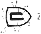
- Figure 1 is a schematic drawing which shows the shape of the emblem used in Example 1 and the shape of the bead of glue used.
- the emblem has the shape of a substantially triangular shield, with a convex curved upper side and two convex curved sides which meet at a vertex.
- the glue pattern shown in Figure 1 will be described starting from the right-hand bottom end (A) and proceeding in an anti-clockwise direction.
- the glue pattern has a first side which is substantially parallel to the convex curved right-hand side, a top side which is substantially parallel to the upper side of the shield, and a second side substantially parallel to the convex curved left-hand side.
- One or more of the sides of the glue pattern may also be segmented.
- the ends (A, B) of the glue pattern do not coincide.
- a distance substantially corresponding to the width of the bead of glue is provided between the two ends of the glue pattern.
- the distance between the two ends (A, B) of the glue pattern may also be greater than the width of the bead of glue.
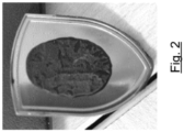
- Table 1 shows the data relating to the gripping force and the ratio between the gripping force and the surface area of the emblem and the amount of glue used, as measured by means of the destructive test described above.
- Figure 2 shows the emblem and the residual glue at the end of this destructive test.
- the glue after gluing covers a portion of the surface of the emblem equal to about 50-60%. This percentage also depends on the concavity of the emblem and therefore may also be smaller or greater than this range.
- the glue pattern shown in Figure 3 is substantially in the shape of a G.
- two perpendicular diameters (C, D) dividing the emblem into four quadrants are shown.
- the glue pattern will be described starting from the top end A (top right-hand quadrant) and proceeding in an anti-clockwise direction. It follows a curved path substantially parallel to the circumference of the emblem up to the diameter C in the bottom right-hand quadrant, where it curves towards the centre O forming a segment substantially parallel to the diameter C.
- the end B may coincide with the centre of the circumference O or may be close thereto.
- the end A is not situated on the diameter C.
- a distance substantially corresponding to the width of the bead of glue is provided between the end A and the segment of the bead of glue which lies on the diameter C. According to embodiments, this distance may also be greater than the width of the bead of glue.
- Table 1 shows the data relating to the gripping force and the ratio between the gripping force and the surface area of the emblem and the amount of glue used, as measured by means of the destructive test described above.
- Figure 4 shows the emblem and the residual glue at the end of this destructive test.
- the glue after gluing covers a portion of the surface of the emblem equal to about 55-65%. This percentage also depends on the concavity of the emblem and therefore may also be smaller or greater than this range.
- Figure 5 shows the circle-shaped emblem used in Example 3.
- the glue pattern shown in Figure 5 is substantially in the shape of a S.
- two perpendicular diameters (C, D) dividing the emblem into four quadrants are shown.
- the glue pattern will be described starting from the top end A (top right-hand quadrant) and proceeding in an anti-clockwise direction. It follows a curved path, from the top right-hand quadrant to the top left-hand quadrant, substantially parallel to the circumference of the emblem up to the diameter C. Then it proceeds with a segment substantially parallel to the diameter C and continues along a curved path, from the bottom right-hand quadrant to the bottom left-hand quadrant, substantially parallel to the circumference of the emblem.
- the ends A and B are not situated on the diameter C.
- a distance substantially corresponding to the width of the bead of glue is provided between the ends A and/or B and the bead segment lying on the diameter C. According to embodiments, this distance may also be greater than the width of the bead of glue.
- Table 1 shows the data relating to the gripping force and the ratio between the gripping force and the surface area of the emblem and the amount of glue used, as measured by means of the destructive test described above.
- Figure 6 shows the emblem and the residual glue at the end of this destructive test.
- the glue after gluing covers a portion of the surface of the emblem equal to about 60-70%. This percentage also depends on the concavity of the emblem and therefore may also be smaller or greater than this range.
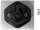
- the glue pattern shown in Figure 7 is substantially in the shape of a G.
- two perpendicular straight lines (A, C) dividing the emblem into four quadrants are shown.
- the glue pattern will be described starting from the top end A (top right-hand quadrant) and proceeding in an anti-clockwise direction. It follows a path with segments substantially parallel to each side of the hexagon, namely the perimeter of the emblem, up to the straight line C in the bottom right-hand quadrant, where it curves towards the centre O forming a segment substantially parallel to the straight line C.
- the end B may coincide with the centre of the circumference O, or may be close thereto.
- the end A is not situated on the straight line C.
- a distance substantially corresponding to the width of the bead of glue is provided between the end A and the segment of the bead of glue lying on the straight line C. According to embodiments, this distance may also be greater than the width of the bead of glue.
- Table 1 shows the data relating to the gripping force and the ratio between the gripping force and the surface area of the emblem and the amount of glue used, as measured by means of the destructive test described above.
- Figure 8 shows the emblem and the residual glue at the end of this destructive test.
- the glue after gluing covers a portion of the surface of the emblem equal to about 60-70%. This percentage also depends on the concavity of the emblem and therefore may also be smaller or greater than this range.
- Example 5 An emblem in the shape of a substantially triangular shield, with convex curved upper side and two convex curved sides which meet at a vertex, was used in Example 5 ( Fig. 9 ).
- the glue pattern shown in Figure 9 has a shape comparable to that of a question mark.
- two perpendicular straight lines (C, D) dividing the emblem into four quadrants are shown.
- the straight line D divides the emblem longitudinally, passing through the vertex
- the straight line C divides the emblem horizontally passing through the point of curvature of the right-hand and left-hand sides.
- the bead of glue will be described starting from the bottom point (A) and proceeding in an anti-clockwise direction. It comprises a first segment substantially parallel to the straight line D, a second oblique segment extending from the straight line D towards the straight line C, then a segment substantially parallel to the right-hand convex curved side, a top segment substantially parallel to the upper side of the shield, and finally a segment substantially parallel to the left-hand convex curved side.
- the ends (A, B) of the bead of glue do not coincide.
- a distance substantially corresponding to the width of the bead of glue is provided between the two ends (A, B) of the bead of glue.
- the distance between the two ends (A, B) of the bead of glue may also be greater than the width of the bead of glue.
- Table 1 shows the data relating to the gripping force and the ratio between the gripping force and the surface area of the emblem and the amount of glue used, as measured by means of the destructive test described above.
- Figure 10 shows the emblem and the residual glue at the end of this destructive test.
- the glue after gluing covers a portion of the surface of the emblem equal to about 90-96%. This percentage also depends on the concavity of the emblem and therefore may also be smaller or greater than this range.
Landscapes
- Engineering & Computer Science (AREA)
- Mechanical Engineering (AREA)
- Vehicle Waterproofing, Decoration, And Sanitation Devices (AREA)
Applications Claiming Priority (1)
| Application Number | Priority Date | Filing Date | Title |
|---|---|---|---|
| IT202100030791 | 2021-12-06 |
Publications (1)
| Publication Number | Publication Date |
|---|---|
| EP4197861A1 true EP4197861A1 (de) | 2023-06-21 |
Family
ID=80461576
Family Applications (1)
| Application Number | Title | Priority Date | Filing Date |
|---|---|---|---|
| EP22211433.2A Pending EP4197861A1 (de) | 2021-12-06 | 2022-12-05 | Verfahren zur befestigung eines emblems an einer abdeckung eines kraftfahrzeuglenkrads |
Country Status (1)
| Country | Link |
|---|---|
| EP (1) | EP4197861A1 (de) |
Citations (6)
| Publication number | Priority date | Publication date | Assignee | Title |
|---|---|---|---|---|
| KR200385471Y1 (ko) * | 2005-03-04 | 2005-05-27 | 주식회사 엘지화학 | 엠블렘 하우징 및 이를 이용한 에어백용 엠블렘 조립체 |
| DE202006008504U1 (de) * | 2006-05-29 | 2006-08-17 | Schreiner Group Gmbh & Co. Kg | Selbstklebendes Dekor-Element |
| US20070035111A1 (en) | 2005-08-09 | 2007-02-15 | Hyundai Mobis Co., Ltd. | Emblum assembly of automobile |
| US20110101653A1 (en) * | 2009-09-16 | 2011-05-05 | Gm Global Technology Operations, Inc. | Passenger protection device for a vehicle |
| FR3010360A1 (fr) * | 2013-09-11 | 2015-03-13 | Peugeot Citroen Automobiles Sa | Module airbag |
| WO2020112430A1 (en) * | 2018-11-29 | 2020-06-04 | Corning Incorporated | Adhering glass cover sheet to a frame |
-
2022
- 2022-12-05 EP EP22211433.2A patent/EP4197861A1/de active Pending
Patent Citations (6)
| Publication number | Priority date | Publication date | Assignee | Title |
|---|---|---|---|---|
| KR200385471Y1 (ko) * | 2005-03-04 | 2005-05-27 | 주식회사 엘지화학 | 엠블렘 하우징 및 이를 이용한 에어백용 엠블렘 조립체 |
| US20070035111A1 (en) | 2005-08-09 | 2007-02-15 | Hyundai Mobis Co., Ltd. | Emblum assembly of automobile |
| DE202006008504U1 (de) * | 2006-05-29 | 2006-08-17 | Schreiner Group Gmbh & Co. Kg | Selbstklebendes Dekor-Element |
| US20110101653A1 (en) * | 2009-09-16 | 2011-05-05 | Gm Global Technology Operations, Inc. | Passenger protection device for a vehicle |
| FR3010360A1 (fr) * | 2013-09-11 | 2015-03-13 | Peugeot Citroen Automobiles Sa | Module airbag |
| WO2020112430A1 (en) * | 2018-11-29 | 2020-06-04 | Corning Incorporated | Adhering glass cover sheet to a frame |
Similar Documents
| Publication | Publication Date | Title |
|---|---|---|
| US6620371B1 (en) | Method of manufacturing an in-mold laminate component | |
| US7384061B2 (en) | Trim panel and a method of manufacture | |
| US8104813B2 (en) | Vehicle interior trim panel | |
| US6756003B2 (en) | Method of attaching thermoplastic attachments to a substrate | |
| JPH10258699A (ja) | エアバッグ用パッドとその製造方法 | |
| EP2998102B1 (de) | Vibrationsschweissvorrichtung und vibrationsschweissverfahren | |
| JP5676753B2 (ja) | 車両内装アセンブリ | |
| EP4197861A1 (de) | Verfahren zur befestigung eines emblems an einer abdeckung eines kraftfahrzeuglenkrads | |
| US20070042157A1 (en) | Trim panel with edge seal | |
| JP2011207380A (ja) | 自動車用内装部品並びにその製造方法 | |
| WO2006072177A1 (en) | In-mould coating of polycarbonate panels | |
| JP4440555B2 (ja) | 加飾成形品の製造方法およびその装置 | |
| JPH06170883A (ja) | 樹脂製ウィンド部材の製造方法 | |
| JP2009078419A (ja) | 内装品の真空成形方法 | |
| US20070278770A1 (en) | Insert molded feature for airbag covers | |
| US9713997B2 (en) | Interior panels including substrates with film inserts for defining integrated airbag deployment doors for motor vehicles and methods of making the same | |
| US20120074675A1 (en) | Cover for airbag apparatus | |
| US20200269471A1 (en) | Method for producing a trim part for vehicles, using a temporary seal | |
| JP6744254B2 (ja) | 車体の樹脂パネル部品及びその製造方法 | |
| KR101163608B1 (ko) | 스티어링 휠용 에어백 커버 제조방법 | |
| EP3659775B1 (de) | Airbagschacht mit integrierter dichtung | |
| CN216173885U (zh) | 具有翻转功能的固化装置 | |
| US11897206B2 (en) | Method for attaching emblem to vehicle seat | |
| JP5930659B2 (ja) | 車両用内装部品 | |
| US20160311391A1 (en) | Interior panels including substrates with inserts for defining integrated airbag deployment doors for motor vehicles and methods of making the same |
Legal Events
| Date | Code | Title | Description |
|---|---|---|---|
| PUAI | Public reference made under article 153(3) epc to a published international application that has entered the european phase |
Free format text: ORIGINAL CODE: 0009012 |
|
| STAA | Information on the status of an ep patent application or granted ep patent |
Free format text: STATUS: THE APPLICATION HAS BEEN PUBLISHED |
|
| AK | Designated contracting states |
Kind code of ref document: A1 Designated state(s): AL AT BE BG CH CY CZ DE DK EE ES FI FR GB GR HR HU IE IS IT LI LT LU LV MC ME MK MT NL NO PL PT RO RS SE SI SK SM TR |
|
| STAA | Information on the status of an ep patent application or granted ep patent |
Free format text: STATUS: REQUEST FOR EXAMINATION WAS MADE |
|
| 17P | Request for examination filed |
Effective date: 20231218 |
|
| RBV | Designated contracting states (corrected) |
Designated state(s): AL AT BE BG CH CY CZ DE DK EE ES FI FR GB GR HR HU IE IS IT LI LT LU LV MC ME MK MT NL NO PL PT RO RS SE SI SK SM TR |