EP4197832B1 - Wärmeverwaltungsschleife für elektrofahrzeug, steuerungsverfahren und reines elektrofahrzeug - Google Patents
Wärmeverwaltungsschleife für elektrofahrzeug, steuerungsverfahren und reines elektrofahrzeug Download PDFInfo
- Publication number
- EP4197832B1 EP4197832B1 EP22213081.7A EP22213081A EP4197832B1 EP 4197832 B1 EP4197832 B1 EP 4197832B1 EP 22213081 A EP22213081 A EP 22213081A EP 4197832 B1 EP4197832 B1 EP 4197832B1
- Authority
- EP
- European Patent Office
- Prior art keywords
- pipe system
- port
- power battery
- pipe
- series
- Prior art date
- Legal status (The legal status is an assumption and is not a legal conclusion. Google has not performed a legal analysis and makes no representation as to the accuracy of the status listed.)
- Active
Links
Images


Classifications
-
- B—PERFORMING OPERATIONS; TRANSPORTING
- B60—VEHICLES IN GENERAL
- B60H—ARRANGEMENTS OF HEATING, COOLING, VENTILATING OR OTHER AIR-TREATING DEVICES SPECIALLY ADAPTED FOR PASSENGER OR GOODS SPACES OF VEHICLES
- B60H1/00—Heating, cooling or ventilating devices
- B60H1/00271—HVAC devices specially adapted for particular vehicle parts or components and being connected to the vehicle HVAC unit
- B60H1/00278—HVAC devices specially adapted for particular vehicle parts or components and being connected to the vehicle HVAC unit for the battery
-
- B—PERFORMING OPERATIONS; TRANSPORTING
- B60—VEHICLES IN GENERAL
- B60H—ARRANGEMENTS OF HEATING, COOLING, VENTILATING OR OTHER AIR-TREATING DEVICES SPECIALLY ADAPTED FOR PASSENGER OR GOODS SPACES OF VEHICLES
- B60H1/00—Heating, cooling or ventilating devices
- B60H1/00485—Valves for air-conditioning devices, e.g. thermostatic valves
-
- B—PERFORMING OPERATIONS; TRANSPORTING
- B60—VEHICLES IN GENERAL
- B60H—ARRANGEMENTS OF HEATING, COOLING, VENTILATING OR OTHER AIR-TREATING DEVICES SPECIALLY ADAPTED FOR PASSENGER OR GOODS SPACES OF VEHICLES
- B60H1/00—Heating, cooling or ventilating devices
- B60H1/00642—Control systems or circuits; Control members or indication devices for heating, cooling or ventilating devices
- B60H1/00814—Control systems or circuits characterised by their output, for controlling particular components of the heating, cooling or ventilating installation
- B60H1/00878—Control systems or circuits characterised by their output, for controlling particular components of the heating, cooling or ventilating installation the components being temperature regulating devices
- B60H1/00885—Controlling the flow of heating or cooling liquid, e.g. valves or pumps
-
- B—PERFORMING OPERATIONS; TRANSPORTING
- B60—VEHICLES IN GENERAL
- B60H—ARRANGEMENTS OF HEATING, COOLING, VENTILATING OR OTHER AIR-TREATING DEVICES SPECIALLY ADAPTED FOR PASSENGER OR GOODS SPACES OF VEHICLES
- B60H1/00—Heating, cooling or ventilating devices
- B60H1/02—Heating, cooling or ventilating devices the heat being derived from the propulsion plant
- B60H1/03—Heating, cooling or ventilating devices the heat being derived from the propulsion plant and from a source other than the propulsion plant
-
- B—PERFORMING OPERATIONS; TRANSPORTING
- B60—VEHICLES IN GENERAL
- B60H—ARRANGEMENTS OF HEATING, COOLING, VENTILATING OR OTHER AIR-TREATING DEVICES SPECIALLY ADAPTED FOR PASSENGER OR GOODS SPACES OF VEHICLES
- B60H1/00—Heating, cooling or ventilating devices
- B60H1/02—Heating, cooling or ventilating devices the heat being derived from the propulsion plant
- B60H1/14—Heating, cooling or ventilating devices the heat being derived from the propulsion plant other than from cooling liquid of the plant
- B60H1/143—Heating, cooling or ventilating devices the heat being derived from the propulsion plant other than from cooling liquid of the plant the heat being derived from cooling an electric component, e.g. electric motors, electric circuits, fuel cells or batteries
-
- B—PERFORMING OPERATIONS; TRANSPORTING
- B60—VEHICLES IN GENERAL
- B60H—ARRANGEMENTS OF HEATING, COOLING, VENTILATING OR OTHER AIR-TREATING DEVICES SPECIALLY ADAPTED FOR PASSENGER OR GOODS SPACES OF VEHICLES
- B60H1/00—Heating, cooling or ventilating devices
- B60H1/22—Heating, cooling or ventilating devices the heat source being other than the propulsion plant
- B60H1/2215—Heating, cooling or ventilating devices the heat source being other than the propulsion plant the heat being derived from electric heaters
- B60H1/2221—Heating, cooling or ventilating devices the heat source being other than the propulsion plant the heat being derived from electric heaters arrangements of electric heaters for heating an intermediate liquid
-
- B—PERFORMING OPERATIONS; TRANSPORTING
- B60—VEHICLES IN GENERAL
- B60H—ARRANGEMENTS OF HEATING, COOLING, VENTILATING OR OTHER AIR-TREATING DEVICES SPECIALLY ADAPTED FOR PASSENGER OR GOODS SPACES OF VEHICLES
- B60H1/00—Heating, cooling or ventilating devices
- B60H1/32—Cooling devices
- B60H1/3204—Cooling devices using compression
- B60H1/3228—Cooling devices using compression characterised by refrigerant circuit configurations
- B60H1/32284—Cooling devices using compression characterised by refrigerant circuit configurations comprising two or more secondary circuits, e.g. at evaporator and condenser side
-
- B—PERFORMING OPERATIONS; TRANSPORTING
- B60—VEHICLES IN GENERAL
- B60K—ARRANGEMENT OR MOUNTING OF PROPULSION UNITS OR OF TRANSMISSIONS IN VEHICLES; ARRANGEMENT OR MOUNTING OF PLURAL DIVERSE PRIME-MOVERS IN VEHICLES; AUXILIARY DRIVES FOR VEHICLES; INSTRUMENTATION OR DASHBOARDS FOR VEHICLES; ARRANGEMENTS IN CONNECTION WITH COOLING, AIR INTAKE, GAS EXHAUST OR FUEL SUPPLY OF PROPULSION UNITS IN VEHICLES
- B60K11/00—Arrangement in connection with cooling of propulsion units
- B60K11/02—Arrangement in connection with cooling of propulsion units with liquid cooling
-
- B—PERFORMING OPERATIONS; TRANSPORTING
- B60—VEHICLES IN GENERAL
- B60L—PROPULSION OF ELECTRICALLY-PROPELLED VEHICLES; SUPPLYING ELECTRIC POWER FOR AUXILIARY EQUIPMENT OF ELECTRICALLY-PROPELLED VEHICLES; ELECTRODYNAMIC BRAKE SYSTEMS FOR VEHICLES IN GENERAL; MAGNETIC SUSPENSION OR LEVITATION FOR VEHICLES; MONITORING OPERATING VARIABLES OF ELECTRICALLY-PROPELLED VEHICLES; ELECTRIC SAFETY DEVICES FOR ELECTRICALLY-PROPELLED VEHICLES
- B60L58/00—Methods or circuit arrangements for monitoring or controlling batteries or fuel cells, specially adapted for electric vehicles
- B60L58/10—Methods or circuit arrangements for monitoring or controlling batteries or fuel cells, specially adapted for electric vehicles for monitoring or controlling batteries
- B60L58/24—Methods or circuit arrangements for monitoring or controlling batteries or fuel cells, specially adapted for electric vehicles for monitoring or controlling batteries for controlling the temperature of batteries
- B60L58/26—Methods or circuit arrangements for monitoring or controlling batteries or fuel cells, specially adapted for electric vehicles for monitoring or controlling batteries for controlling the temperature of batteries by cooling
-
- B—PERFORMING OPERATIONS; TRANSPORTING
- B60—VEHICLES IN GENERAL
- B60L—PROPULSION OF ELECTRICALLY-PROPELLED VEHICLES; SUPPLYING ELECTRIC POWER FOR AUXILIARY EQUIPMENT OF ELECTRICALLY-PROPELLED VEHICLES; ELECTRODYNAMIC BRAKE SYSTEMS FOR VEHICLES IN GENERAL; MAGNETIC SUSPENSION OR LEVITATION FOR VEHICLES; MONITORING OPERATING VARIABLES OF ELECTRICALLY-PROPELLED VEHICLES; ELECTRIC SAFETY DEVICES FOR ELECTRICALLY-PROPELLED VEHICLES
- B60L58/00—Methods or circuit arrangements for monitoring or controlling batteries or fuel cells, specially adapted for electric vehicles
- B60L58/10—Methods or circuit arrangements for monitoring or controlling batteries or fuel cells, specially adapted for electric vehicles for monitoring or controlling batteries
- B60L58/24—Methods or circuit arrangements for monitoring or controlling batteries or fuel cells, specially adapted for electric vehicles for monitoring or controlling batteries for controlling the temperature of batteries
- B60L58/27—Methods or circuit arrangements for monitoring or controlling batteries or fuel cells, specially adapted for electric vehicles for monitoring or controlling batteries for controlling the temperature of batteries by heating
-
- H—ELECTRICITY
- H01—ELECTRIC ELEMENTS
- H01M—PROCESSES OR MEANS, e.g. BATTERIES, FOR THE DIRECT CONVERSION OF CHEMICAL ENERGY INTO ELECTRICAL ENERGY
- H01M10/00—Secondary cells; Manufacture thereof
- H01M10/60—Heating or cooling; Temperature control
- H01M10/61—Types of temperature control
- H01M10/613—Cooling or keeping cold
-
- H—ELECTRICITY
- H01—ELECTRIC ELEMENTS
- H01M—PROCESSES OR MEANS, e.g. BATTERIES, FOR THE DIRECT CONVERSION OF CHEMICAL ENERGY INTO ELECTRICAL ENERGY
- H01M10/00—Secondary cells; Manufacture thereof
- H01M10/60—Heating or cooling; Temperature control
- H01M10/61—Types of temperature control
- H01M10/615—Heating or keeping warm
-
- H—ELECTRICITY
- H01—ELECTRIC ELEMENTS
- H01M—PROCESSES OR MEANS, e.g. BATTERIES, FOR THE DIRECT CONVERSION OF CHEMICAL ENERGY INTO ELECTRICAL ENERGY
- H01M10/00—Secondary cells; Manufacture thereof
- H01M10/60—Heating or cooling; Temperature control
- H01M10/62—Heating or cooling; Temperature control specially adapted for specific applications
- H01M10/625—Vehicles
-
- H—ELECTRICITY
- H01—ELECTRIC ELEMENTS
- H01M—PROCESSES OR MEANS, e.g. BATTERIES, FOR THE DIRECT CONVERSION OF CHEMICAL ENERGY INTO ELECTRICAL ENERGY
- H01M10/00—Secondary cells; Manufacture thereof
- H01M10/60—Heating or cooling; Temperature control
- H01M10/63—Control systems
- H01M10/635—Control systems based on ambient temperature
-
- H—ELECTRICITY
- H01—ELECTRIC ELEMENTS
- H01M—PROCESSES OR MEANS, e.g. BATTERIES, FOR THE DIRECT CONVERSION OF CHEMICAL ENERGY INTO ELECTRICAL ENERGY
- H01M10/00—Secondary cells; Manufacture thereof
- H01M10/60—Heating or cooling; Temperature control
- H01M10/63—Control systems
- H01M10/637—Control systems characterised by the use of reversible temperature-sensitive devices, e.g. NTC, PTC or bimetal devices; characterised by control of the internal current flowing through the cells, e.g. by switching
-
- H—ELECTRICITY
- H01—ELECTRIC ELEMENTS
- H01M—PROCESSES OR MEANS, e.g. BATTERIES, FOR THE DIRECT CONVERSION OF CHEMICAL ENERGY INTO ELECTRICAL ENERGY
- H01M10/00—Secondary cells; Manufacture thereof
- H01M10/60—Heating or cooling; Temperature control
- H01M10/65—Means for temperature control structurally associated with the cells
- H01M10/655—Solid structures for heat exchange or heat conduction
- H01M10/6556—Solid parts with flow channel passages or pipes for heat exchange
-
- H—ELECTRICITY
- H01—ELECTRIC ELEMENTS
- H01M—PROCESSES OR MEANS, e.g. BATTERIES, FOR THE DIRECT CONVERSION OF CHEMICAL ENERGY INTO ELECTRICAL ENERGY
- H01M10/00—Secondary cells; Manufacture thereof
- H01M10/60—Heating or cooling; Temperature control
- H01M10/65—Means for temperature control structurally associated with the cells
- H01M10/656—Means for temperature control structurally associated with the cells characterised by the type of heat-exchange fluid
- H01M10/6567—Liquids
- H01M10/6568—Liquids characterised by flow circuits, e.g. loops, located externally to the cells or cell casings
-
- H—ELECTRICITY
- H01—ELECTRIC ELEMENTS
- H01M—PROCESSES OR MEANS, e.g. BATTERIES, FOR THE DIRECT CONVERSION OF CHEMICAL ENERGY INTO ELECTRICAL ENERGY
- H01M10/00—Secondary cells; Manufacture thereof
- H01M10/60—Heating or cooling; Temperature control
- H01M10/65—Means for temperature control structurally associated with the cells
- H01M10/656—Means for temperature control structurally associated with the cells characterised by the type of heat-exchange fluid
- H01M10/6569—Fluids undergoing a liquid-gas phase change or transition, e.g. evaporation or condensation
-
- H—ELECTRICITY
- H01—ELECTRIC ELEMENTS
- H01M—PROCESSES OR MEANS, e.g. BATTERIES, FOR THE DIRECT CONVERSION OF CHEMICAL ENERGY INTO ELECTRICAL ENERGY
- H01M10/00—Secondary cells; Manufacture thereof
- H01M10/60—Heating or cooling; Temperature control
- H01M10/65—Means for temperature control structurally associated with the cells
- H01M10/657—Means for temperature control structurally associated with the cells by electric or electromagnetic means
- H01M10/6571—Resistive heaters
-
- H—ELECTRICITY
- H01—ELECTRIC ELEMENTS
- H01M—PROCESSES OR MEANS, e.g. BATTERIES, FOR THE DIRECT CONVERSION OF CHEMICAL ENERGY INTO ELECTRICAL ENERGY
- H01M10/00—Secondary cells; Manufacture thereof
- H01M10/60—Heating or cooling; Temperature control
- H01M10/66—Heat-exchange relationships between the cells and other systems, e.g. central heating systems or fuel cells
- H01M10/663—Heat-exchange relationships between the cells and other systems, e.g. central heating systems or fuel cells the system being an air-conditioner or an engine
-
- B—PERFORMING OPERATIONS; TRANSPORTING
- B60—VEHICLES IN GENERAL
- B60H—ARRANGEMENTS OF HEATING, COOLING, VENTILATING OR OTHER AIR-TREATING DEVICES SPECIALLY ADAPTED FOR PASSENGER OR GOODS SPACES OF VEHICLES
- B60H1/00—Heating, cooling or ventilating devices
- B60H1/00271—HVAC devices specially adapted for particular vehicle parts or components and being connected to the vehicle HVAC unit
- B60H2001/00307—Component temperature regulation using a liquid flow
-
- Y—GENERAL TAGGING OF NEW TECHNOLOGICAL DEVELOPMENTS; GENERAL TAGGING OF CROSS-SECTIONAL TECHNOLOGIES SPANNING OVER SEVERAL SECTIONS OF THE IPC; TECHNICAL SUBJECTS COVERED BY FORMER USPC CROSS-REFERENCE ART COLLECTIONS [XRACs] AND DIGESTS
- Y02—TECHNOLOGIES OR APPLICATIONS FOR MITIGATION OR ADAPTATION AGAINST CLIMATE CHANGE
- Y02E—REDUCTION OF GREENHOUSE GAS [GHG] EMISSIONS, RELATED TO ENERGY GENERATION, TRANSMISSION OR DISTRIBUTION
- Y02E60/00—Enabling technologies; Technologies with a potential or indirect contribution to GHG emissions mitigation
- Y02E60/10—Energy storage using batteries
-
- Y—GENERAL TAGGING OF NEW TECHNOLOGICAL DEVELOPMENTS; GENERAL TAGGING OF CROSS-SECTIONAL TECHNOLOGIES SPANNING OVER SEVERAL SECTIONS OF THE IPC; TECHNICAL SUBJECTS COVERED BY FORMER USPC CROSS-REFERENCE ART COLLECTIONS [XRACs] AND DIGESTS
- Y02—TECHNOLOGIES OR APPLICATIONS FOR MITIGATION OR ADAPTATION AGAINST CLIMATE CHANGE
- Y02T—CLIMATE CHANGE MITIGATION TECHNOLOGIES RELATED TO TRANSPORTATION
- Y02T10/00—Road transport of goods or passengers
- Y02T10/60—Other road transportation technologies with climate change mitigation effect
- Y02T10/70—Energy storage systems for electromobility, e.g. batteries
Definitions
- the present invention belongs to a technical field of thermal management of a whole vehicle of a new energy vehicle, and especially to an electric vehicle thermal management loop, a control method, and a pure electric vehicle.
- New energy vehicles become a main development direction in an automotive industry.
- Current new energy vehicles are mainly pure electric and hydrogen fueled vehicles.
- Pure electric vehicles are limited by current battery material characteristics and capacity bottleneck, endurance of pure electric vehicles cannot have equivalent endurance of traditional fuel vehicles, especially the endurance in low-temperature environment in winter, which is also a main concern of consumers over pure electric vehicles.
- Both a passenger compartment and a power battery need to be heated in a low-temperature environment in winter.
- a heating source is generally realized through PTC.
- electric heating efficiency of PTC is only about 0.95. Therefore, in the low-temperature environment, a level of the heating energy consumption of the pure electric vehicle directly affects the endurance of the whole vehicle.
- energy consumption of temperature control of power batteries is large, which affects vehicle endurance and fails to meet actual demands.
- US 2021/0053412 A1 discloses a heat pump system for a vehicle, the system may include a cooling apparatus including a radiator, a first water pump, a first valve, and a reservoir tank which are connected through a coolant line, and configured to circulate a coolant in the coolant line to cool at least one electrical component provided in the coolant line; a battery cooling apparatus configured to include a battery coolant line connected to the reservoir tank through a second valve, and a second water pump and a battery module which are connected through the battery coolant line to circulate the coolant in the battery module; and a heating apparatus including a heating line connected to the coolant line through a third valve to heat a vehicle interior by use of a coolant and a third water pump provided on the heating line, and a heater.
- a cooling apparatus including a radiator, a first water pump, a first valve, and a reservoir tank which are connected through a coolant line, and configured to circulate a coolant in the coolant line to cool at least one electrical component
- an objective of the present invention is to provide a thermal management loop of an electric vehicle, a control method, and a pure electric vehicle, which use thermal coupling of heating pump, cooling loops of driving motor, and thermal management loops of a power battery to achieve efficient thermal management of a whole vehicle and reduce energy consumption of the whole vehicle.
- the present invention provides a thermal management loop of an electric vehicle according to claim 1, comprising:
- a passenger compartment temperature control pipe system which comprises an electric compressor, an outdoor heat exchanger, an evaporator, a gas-liquid separator, an in-vehicle condenser, and a heat exchange pipe, and A second control pipe system, configured to enable the passenger compartment temperature control pipe system to switch between the following two states:
- the first control pipe system is configured to enable the motor cooling pipe system and the power battery temperature control pipe system to be switched to state 4;
- the first control pipe system comprises a four-way valve, a first three-way valve, and a second three-way valve;
- the second control pipe system comprises:
- the first sub-pipe system is provided with a first electronic expansion valve, which is located at a liquid outlet end of the in-vehicle condenser;
- the power battery temperature control pipe system is provided with a first PTC heater, which is located between the second water pump and the battery cooler; the evaporator and the in-vehicle condenser are both located in an air duct of a vehicle air conditioning system; and a second PTC heater is disposed in the air duct of the vehicle air conditioning system.
- the present invention also provides a control method according to claim 7 for an electric vehicle thermal management loop
- the electric vehicle thermal management loop comprises a driving motor cooling pipe system, a power battery temperature control pipe system, and a passenger compartment temperature control pipe system
- the driving motor cooling pipe system comprises an expansion kettle, a first water pump, a driving motor, and a low-temperature radiator connected in sequence
- the power battery temperature control pipe system comprises a second water pump, a first PTC heater, a battery cooler, and a power battery connected in sequence
- the passenger compartment temperature control pipe system comprises an electric compressor, an outdoor heat exchanger, an evaporator, a gas-liquid separator, an in-vehicle condenser, a heat exchange pipe, and a second PTC heater
- the heat exchange pipe passes through the battery cooler to realize heat exchange with the power battery temperature control pipe system
- the control method comprises:
- the present invention also provides a pure electric vehicle according to claim 8, comprising:
- the electric vehicle thermal management loop also comprises a third pipe system, which comprises a third water pump, a PTC heater, and a heater core connected in series, the heater core is located in an air duct of a vehicle air conditioning system, and the heater core is connected in parallel with both ends of the power battery;
- the third pipe system is provided with a second reversing module, and the second reversing module is configured to enable the third pipe system to switch among following three stations:
- the third pipe system is connected in series with a water-cooled condenser
- the water-cooled condenser comprises a flow channel a and a flow channel b
- the flow channel a and the flow channel b are independent from each other and are able to conduct heat exchange therebetween
- the flow channel a is connected in series with the third-pipe system
- the flow channel b is connected to a high-temperature pipe of the vehicle air conditioning system
- the vehicle air conditioning system comprises an electric compressor, an outdoor heat exchanger, an evaporator, and a gas-liquid separator connected to each other
- the vehicle air conditioning system also comprises a third reversing module, which is configured to enable the vehicle air conditioning system to switch between the following two stations:
- the first reversing module is configured to enable the first pipe system and the second pipe system to be switched to station 5, and the station 5 means that: the expansion kettle, the first water pump, and the driving motor form a closed loop separately; the second water pump and the power battery form a closed loop separately.
- the electric compressor, the outdoor heat exchanger, the evaporator, and the gas-liquid separator are connected in series on a main pipe system, and the main pipe system is a closed loop; one end of the flow channel b is connected to one main pipe system between the electric compressor and the outdoor heat exchanger, and another end of the flow channel b is connected to the main pipe system between the outdoor heat exchanger and the evaporator; and both ends of the second flow channel are respectively connected to both ends of the evaporator;
- the third reversing module comprises:
- the vehicle air conditioning system also comprises a first electronic expansion valve located on a pipe leading from the flow channel b to the outdoor heat exchanger under the status of station II;
- the first reversing module comprises a six-way valve, a first branch pipe, and a second branch pipe;
- the present invention realizes series and parallel operations of the electric vehicle driving motor cooling loop and the power battery cooling loop, which not only enables the power battery to be cooled or heated separately, but also uses heat generated by the motor to heat the power battery, realizes energy recovery and utilization, and reduces vehicle energy consumption.
- the present invention can bypass the power battery, thermally couple a water loop and a cooling loop, thereby transferring the heat generated by the motor to the passenger compartment, realizing auxiliary heating of the passenger compartment, and reducing energy consumption of the air conditioning system.
- the present invention can realize reversing function of cooling and heating conditions of the outdoor heat exchanger through simple control, effectively reduce the energy consumption of the systems and improve battery endurance on a premise of meeting cooling and heating demands.
- the present invention can use the cooling loop of the driving motor to cool the power battery, and can effectively reduce load of the air conditioning system when cooling demand of the power battery is not high.
- the present invention can use the air conditioning system to cool the power battery, and can effectively improve cooling efficiency when the power battery cooling demand is high.
- the present invention can use the PTC heater to heat the power battery, and can effectively improve the heating efficiency when the power battery has a high heating demand.
- the present invention realizes the series and parallel operations of the driving motor cooling loop and the power battery cooling loop of the electric vehicle, the low-temperature radiator of the bypass driving motor loop, the bypass power battery, the thermal coupling of the water loop and the cooling loop, the bypass of the passenger compartment heat exchanger, the reversing of the cooling and heating conditions of the outdoor heat exchanger, the use of heat pumps for heating the power battery and other functions. While ensuring the temperature control efficiency, the present invention can reduce energy consumption of the systems and improve vehicle endurance.
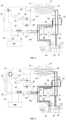
- an electric vehicle thermal management loop comprises a driving motor cooling pipe system, a power battery temperature control pipe system, a passenger compartment temperature control pipe system, a first control pipe system, and a second control pipe system.
- the low-temperature radiator 14 and the outdoor heat exchanger 42 are both located behind a grille 71 on a front face of the vehicle, and the low-temperature radiator 14 is located in front of the outdoor heat exchanger 42, and a cooling fan 72 is disposed a rear side of the outdoor heat exchanger 42.
- the first control pipe system is located between the driving motor cooling pipe system and the power battery temperature control pipe system.
- the first control pipe system is configured to enable the driving motor cooling pipe system and the power battery temperature control pipe system to switch among following four states:
- the above four states can be selectively set, for example, only state 1, state 2, and state 3 can be set.
- the first control pipe system comprises a six-way valve 31, which comprises:
- the six-way valve 31 is configured to be able to switch among at least following four working stations:
- the station 1, the station 2, the station 3, and the station 4 of the six-way valve 31 respectively realize the state 1, the state 2, the state 3, and the state 4.
- the second control pipe system is configured to enable the passenger compartment temperature control pipe system to switch between the following two states:
- the second control pipe system comprises:
- the passenger compartment temperature control pipe system is in a refrigeration state.
- the passenger compartment temperature control pipe system is in a heating state.
- the communication with or disconnection of the second sub-pipe system 402 is related to heat exchange between the passenger compartment temperature control pipe system and the power battery temperature control pipe system.
- Effects of the heat exchange are mainly in two aspects.
- the power battery 24 is cooled simultaneously during a cooling process of the passenger compartment temperature control pipe system; and on the other hand, the power battery temperature control pipe system absorbs heat generated by the motor during a heating process of the passenger compartment temperature control pipe system, thereby improving the heating effect of the passenger compartment temperature control pipe system, realizing energy recovery and reducing heating energy consumption.
- the first control valve assembly comprises:
- the two-way solenoid valves of the present invention are stop valves, the stop valve has two stations of conduction and disconnection.
- the second control valve assembly comprises a third two-way solenoid valve 53 disposed on the third sub-pipe system 403.
- a first electronic expansion valve 54 is disposed on the first sub-pipe system 401, and the first electronic expansion valve 54 is located at an outlet end of the in-vehicle condenser 45.
- a second electronic expansion valve 56 is disposed on the second sub-pipe system 402, and the second electronic expansion valve 56 is located at an inlet end of the heat exchange pipe 46.
- a third electronic expansion valve 55 is disposed at an inlet end of the evaporator 43.
- the present invention can realize independent control of the in-vehicle condenser 45, the evaporator 43, and heat exchange pipe 46 through the above electronic expansion valves, so as to finely control the pipe systems according to actual temperature control demands.
- the main pipe system 400 is provided with a one-way valve 57, which is located on the main pipe system 400 between the first sub-pipe system 401 and the second sub-pipe system 402.
- the following positions are provided with temperature sensors: an outlet of the electric compressor 41, a surface of the outdoor heat exchanger 42, a suction port of the electric compressor 41, a surface of the evaporator 43, an inlet of the driving motor 13, and an inlet of the power battery 24.
- an outlet of the in-vehicle condenser 45 and an outlet of the evaporator 43 are provided with pressure sensors and temperature sensors.
- temperature sensors and pressure temperature sensors can be connected to a trip computer or an independent controller, so as to adjust operation status of the pipe systems in real time according to ambient temperature and pipe operation parameters.
- the present invention also provides a control method of the electric vehicle thermal management loop, comprises: controlling the driving motor cooling pipe system and the power battery temperature control pipe system to form independent closed loops respectively, when both the passenger compartment and the power battery 24 have cooling requirements; controlling the electric compressor 41, the outdoor heat exchanger 42, the evaporator 43, and the gas-liquid separator 44 to be connected in series in sequence to form a closed loop, and the heat exchange pipe 46 is connected in parallel with the evaporator 43; controlling the first PTC heater 22 to close; this working condition is often used in hot summer environment, for example, when the ambient temperature is greater than 30 ° C.
- the present invention can improve heating efficiency of the power battery 24 and the passenger compartment through a first PTC heater 22 and a second PTC heater 47.
- a difference between the present embodiment and the embodiment 1 is that only specific embodiments of the first control pipe system and the first control valve assembly are different.
- the first control pipe system comprises a four-way valve 34, a first three-way valve 35, and a second three-way valve 37;
- the first control valve assembly comprises a third three-way valve 58, which is located at a connection node between a front end of the first sub-pipe 401 and the main pipe 400.
- a difference between the present embodiment and embodiment 1 is that only the specific implementation methods of the first control valve assembly are different.
- the first control valve assembly comprises a third three-way valve 58, which is located at a connection node between a front end of the first sub pipe system 401 and the main pipe system 400.
- the present invention realizes a series parallel operation of the cooling loop of the driving motor 13 and the cooling loop of the power battery 24 of the electric vehicle, the low-temperature radiator 14 of the loop of the bypass driving motor 13, the bypass power battery 24, the thermal coupling of the water loop and the refrigerant loop, the bypass of the heat exchanger in the passenger compartment, the reversing of the cooling and heating conditions of the outdoor heat exchanger 42, and effectively reduces energy consumption of the system and improves battery life on a premise of meeting cooling and heating demands .
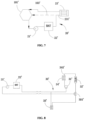
- an electric vehicle thermal management loop comprises a first pipe system 10', a second pipe system 20', and a first reversing module.
- the first pipe system 10' comprises an expansion kettle 11', a first water pump 12', a driving motor 13', and a low-temperature radiator 14' which are connected in series.
- the second pipe system 20' comprises a second water pump 21', a power battery 22', and a battery cooler 23' connected in series.
- the first reversing module is connected between the first pipe system 10' and the second pipe system 20'.
- the first reversing module is configured to enable the first pipe system 10' and the second pipe system 20' to switch among the following four stations:
- the battery cooler 23' comprises a first flow channel 231' and a second flow channel 232'.
- the first flow channel 231' and the second flow channel 232' are independent with each other and can conduct heat exchange therebetween.
- the first flow channel 231' is connected in series to the second pipe system 20', and the second flow channel 232' is connected to the low-temperature pipe of the vehicle air conditioning system.
- the driving motor 13' refers to the cooling water loop of the driving motor 13', not the power structure of the driving motor 13' itself.
- the power battery 22' refers to the cooling water loop of the power battery 22', not the electrochemical structure of the power battery 22'.
- the present invention can selectively connect the power battery 22' to the air conditioning system or the driving motor 13'.
- the battery When connected to the air conditioning system, the battery is cooled.
- cooling liquid of the driving motor 13' can be used to cool the battery; on the other hand, residual heat of the driving motor 13' can be used to heat the battery and reduce system energy consumption.
- the present invention can directly conduct heat exchange between the cooling liquid of the driving motor 13' and the air conditioning system, and can absorb residual heat of the driving motor 13' when the air conditioning system is in heating, thereby reducing the system energy consumption while ensuring the heating effect.
- the third pipe system 30' comprises a third water pump 31', a PTC heater 32', and a heating core 33' connected in series.
- the heating core 33' is located in an air duct of the vehicle air conditioning system, and the heating core 33' is connected in parallel to both ends of the power battery 22';
- the third pipe 30' is provided with a second reversing module, and the second reversing module is configured to enable the third pipe system 30' to switch among following three stations:
- the second reversing module in the present invention can be a three-way proportional valve 301', for example. It can be foreseen that the present invention can also use two stop valves to replace the three-way proportional valve 301'.
- the present invention can also auxiliarily heat the power battery 22' and the passenger compartment through the PTC heater 32', so as to ensure that the power battery 22' works at a suitable temperature and improve electric energy conversion rate.
- the third pipe system 30' is connected in series with a water-cooled condenser 34'.
- the water-cooled condenser 34' comprises a flow channel a341' and a flow channel b342'.
- the flow channel a341' and the flow channel b342' are independent with each other and can conduct heat exchange therebetween.
- the flow channel a341' is connected in series with the third pipe system 30', and the flow channel b 342' is connected to high-temperature pipe of the vehicle air conditioning system.
- the present invention can realize the heat exchange between the third pipe system 30' and the air conditioning system.
- the air conditioning system can be used to heat the passenger compartment.
- the air conditioning system can recover residual heat of the driving motor 13', which reduces the system energy consumption while ensuring heating effect of the passenger compartment.
- the vehicle air conditioning system comprises an electric compressor 41', an outdoor heat exchanger 42', an evaporator 43', and a gas-liquid separator 44' connected to each other; it also comprises a third reversing module, which is configured to enable the vehicle air conditioning system to switch between the following two stations:
- the above station I corresponds to the cooling state of the air conditioner
- the above station II corresponds to the heating state of the air conditioner
- the first reversing module is configured to enable the first pipe system 10' and the second pipe system 20' to be switched to station 5, the station 5 is: the expansion kettle 11', the first water pump 12', and the driving motor 13' form a closed loop independently; the second water pump 21' and the power battery 22' form a closed loop independently.
- the first reversing module can be adjusted to the station 5.
- the first pipe system 10' can conduct cyclic heat storage.
- the first reversing module can be switched to the station 4, so as to transfer the heat in the first pipe system 10' to the air conditioning system, further improving residual heat utilization rate of the driving motor 13', and reducing the system energy consumption.
- the electric compressor 41', the outdoor heat exchanger 42', the evaporator 43' and the gas-liquid separator 44' are connected in series on a main pipe system 40', and the main pipe system 40' is a closed loop.
- One end of the flow channel b342' is connected with the main pipe system 40' between the electric compressor 41' and the outdoor heat exchanger 42', and another end of the flow channel b342' is connected to the main pipe system 40' between the outdoor heat exchanger 42' and the evaporator 43'.
- Both ends of the second flow channel 232' are respectively connected to both ends of the evaporator 43'.
- the power battery 22' when the vehicle is charged, the power battery 22' has a heating demand while the passenger compartment has no heating demand. At this status, the power battery 22' can be communicated with the third pipe system 30', and the heating core 33' can be disconnected from the third pipe system 30'. The third pipe system 30' can be heated either by the air conditioning system or the PTC heater 32' for heating.
- the third reversing module comprises a first stop valve 401', a second stop valve 402', a return branch pipe 404', and a third stop valve 403'.
- the first stop valve 401' is located on the main pipe system 40' between the electric compressor 41' and the outdoor heat exchanger 42';
- the vehicle air conditioning system further comprises a first electronic expansion valve 405', and the first electronic expansion valve 405' is located on a pipe leading from the flow channel b to the outdoor heat exchanger 42' in the station II. Both ends of the first electronic expansion valve 405' are connected in parallel with the first one-way valve 408'. A second one-way valve 409' is connected in series on the return branch pipe 404'. A second electronic expansion valve 406' is connected in series on the second flow channel 232'.
- the vehicle air conditioning system further comprises a third electronic expansion valve 407', and the third electronic expansion valve 407' is located on a pipe leading from the outdoor heat exchanger 42' to the evaporator 43' under the status of station I.
- the first reversing module comprises a six-way valve 101', a first branch pipe 102', and a second branch pipe 103'; one end of the first branch pipe 102' is connected to the pipe between the driving motor 13' and the low-temperature radiator 14', and another end is connected to the six-way valve 101'; one end of the second branch pipe 103' is connected to the pipe between the power battery 22' and the battery cooler 23', and another end is connected to the six-way valve 101'.
- the six-way valve 101' has a first port 1', a second port 2', a third port 3', a fourth port 4', a fifth port 5', and a sixth port 6'.
- the first port 1' is connected to the battery cooler 23'; the second port 2' is connected to the second branch pipe 103'; the third port 3' is connected to the second water pump 21'; the fourth port 4' is connected to the expansion kettle 11'; the fifth port 5' is connected to the first branch pipe 102'; and the sixth port 6' is connected to the low-temperature radiator 14'.
- the six-way valve 101' is configured as follows: the first port 1' is able to be communicated with or disconnected from any one of the third port 3' and the fourth port 4'; the second port 2' is able to be communicated with or disconnected from any one of the third port 3' and the fourth port 4'; the fifth port 5' is able to be communicated with or disconnected from any one of the third port 3' and the fourth port 4'; and the sixth port 6' is able to be communicated with or disconnected from any one of the third port 3' and the fourth port 4'.
- the present invention can also use a combination of multiple stop valves to achieve the above-mentioned control process.
- the low-temperature radiator 14' and the outdoor heat exchanger 42' are located behind a grille 50' on a front face of the vehicle, and a cooling fan 60' is disposed behind the low-temperature radiator 14' and/or outdoor heat exchanger 42'.
- the first pipe system 10' also passes through a wireless charging module 15', an intelligent driving module 16', and a vehicle charger 17' to cool these components.
- the present invention further provides a pure electric vehicle, which comprises: a passenger compartment; a power system; and a thermal management loop, and the thermal management loop comprises a first pipe system 10', a second pipe system 20', and a first reversing module.
- the first pipe system 10' comprises an expansion kettle 11', a first water pump 12', a driving motor 13', and a low-temperature radiator 14' connected in series;
- the second pipe system 20' comprises a second water pump 21', a power battery 22', and a battery cooler 23' connected in series;
- the first reversing module is connected between the first pipe system 10' and the second pipe system 20', and the first reversing module is configured to enable the first pipe system 10' and the second pipe system 20' to switch among the following four stations:
- the present invention also provides a control method of an electric vehicle thermal management loop, specifically: under a high temperature working condition in summer, for example, when the ambient temperature is greater than 30 ° C, both the passenger compartment and the power battery 22' have cooling demands, the electric compressor 41', the cooling fan 60', and an active grid are all turned on, a refrigerant in high temperature and high pressure state enters the outdoor heat exchanger 42' through the first stop valve 401' and becomes liquid after cooling; it reaches the second electronic expansion valve 406' and the third electronic expansion valve 407' respectively through the first one-way valve 408'; the refrigerant throttled by the second electronic expansion valve 406' enters the battery cooler 23' to cool a power battery 22' loop; the refrigerant throttled by the third electronic expansion valve 407' enters the evaporator 43' to cool the passenger compartment.
- the second stop valve 402' since the second stop valve 402' is turned off, the refrigerant will not enter the water-cooled condenser 34' and the third water pump 31' will not work, which can reduce heat load of cooling in the vehicle; under this working condition, the six-way valve 101' on a water way side is in an initial state, the second water pump 21' drives coolant to enter the power battery 22', and then enters the battery cooler 23' for cooling; the cooled coolant returns to the second water pump 21' through the first port 1 and the third port 3 of the six-way valve 101' to cool the battery's internal battery cell.
- the coolant of the loop of the driving motor 13' comes out of the first water pump 12' and is divided into two paths to front and rear driving motors 13' and other components requiring liquid cooling, and then combined into one path to enter the low-temperature radiator 14'; the high temperature coolant is cooled in the low-temperature radiator 14' and then returns to the expansion kettle 11' through the sixth port 6' and the fourth port 4' of the six-way valve 101', and then enters the first water pump 12' again.
- the second electronic expansion valve 406' When ambient temperature is relatively high in spring and autumn working conditions, for example, when the ambient temperature is in the range of 20°C- 30°C, when the passenger compartment has cooling demand, the second electronic expansion valve 406' is turned off, and a working mode of other refrigerant loop components is the same as that in the summer working condition.
- a working mode of the six-way valve 101' is that, the sixth port 6' is communicated with the third port 3', the second port 2' is communicated with the fourth port 4', the driving motor 13' and the loop of the power battery 22' operate in series, and the power battery 22' dissipates heat through the low-temperature radiator 14'.
- the parallel operation mode at the waterway side is the same as that in the summer cooling working condition.
- the working mode of the six-way valve 101' is that, the fifth port 5' is communicated with the third port 3', the second port 2' is communicated with the fourth port 4', bypass the low-temperature radiator 14'; and the coolant enters the second water pump 21' through the fifth port 5' and the third port 3' of the six-way valve 101' after coming out of the front and rear driving motors 13', and then enters into the power battery 22'. After coming out of the power battery 22', the coolant enters the expansion kettle 11' through the second port 2' and the fourth port 4' of the six-way valve 101', and then returns to the first water pump 12' again.
- the high temperature coolant of the loop to the passenger compartment will heat air in the passenger compartment through the heater core 33', and then returns to the water-cooled condenser 34' through the third water pump 31'.
- the high temperature coolant of the loop to the power battery 22' enters the power battery 22' through the second water pump 21' to heat the battery, and returns to the third water pump 31' and then to the water-cooled condenser 34' again.
- Refrigerant at the refrigerant side comes out of the water-cooled condenser 34', and then is throttled by the first electronic expansion valve 405', and enters the outdoor heat exchanger 42' to absorb external environment heat, then enters the gas-liquid separator 44' through the third stop valve 403' and the second one-way valve 409', and returns to the electric compressor 41'.
- the fifth port 5' of the six-way valve 101' is connected to the fourth port 4' of the six-way valve 101', the second port 2' is connected to the third port 3', and the loop of the driving motor 13' bypasses the low-temperature radiator 14' for independent operation to store heat.
- the refrigerant comes out of the water-cooled condenser 34' and arrives at the first electronic expansion valve 405' and the second electronic expansion valve 406' respectively.
- the refrigerant passing through the first electronic expansion valve 405' enters the outdoor heat exchanger 42' to absorb ambient heat, and then enters the gas-liquid separator 44' through the third stop valve 403' and the second one-way valve 409', and returns to the electric compressor 41'.
- the refrigerant passing through the second electronic expansion valve 406' enters the battery cooler 23' to absorb heat at a coolant side, and then returns to the electric compressor 41' again after passing through the gas-liquid separator 44'.
- a state of the six-way valve 101' on a waterway side is that the fifth port 5' is communicated with the first port 1', the second port 2' is communicated with the fourth port 4'.
- the coolant After coming out of the battery cooler 23', the coolant enters the expansion kettle 11' through the second port 2' and the fourth port 4' of the six-way valve 101', and then flows through the front and rear driving motors 13' respectively through the first water pump 12' in two paths, and then it returns to the battery cooler 23' again through the fifth port 5' and the first port 1' of the six-way valve 101'.
- the present invention can heat the coolant in the heating loop through the water-cooled condenser 34' to realize heating of the power battery 22' under a fast charging condition of a low-temperature battery, that is, when only the power battery 22' has the heating demand.
- the present invention realizes the series and parallel operations of the cooling loop of the driving motor 13' and the cooling loop of the power battery 22' of the electric vehicle, the low-temperature radiator 14' of the loop of the bypass driving motor 13', the bypass power battery 22', the thermal coupling of the water loop and the cooling loop, the bypass of the passenger compartment and heat exchanger, the reversing of the cooling and heating conditions of the outdoor heat exchanger, the use of heat pumps for heating the power battery 22' and other functions. While ensuring the temperature control efficiency, the present invention reduces the energy consumption of the systems and improves the vehicle endurance.
- any arrow in the drawings should be considered as an example only, not a limitation.
- the term "or” used here is generally intended to mean “and/or”. When the term is foreseen because it is unclear to provide separation or combination capability, the combination of components or steps will also be deemed to have been specified.
Landscapes
- Engineering & Computer Science (AREA)
- Chemical & Material Sciences (AREA)
- Mechanical Engineering (AREA)
- Physics & Mathematics (AREA)
- Electrochemistry (AREA)
- Manufacturing & Machinery (AREA)
- Chemical Kinetics & Catalysis (AREA)
- Thermal Sciences (AREA)
- General Chemical & Material Sciences (AREA)
- Combustion & Propulsion (AREA)
- Transportation (AREA)
- Automation & Control Theory (AREA)
- Life Sciences & Earth Sciences (AREA)
- Sustainable Development (AREA)
- Sustainable Energy (AREA)
- Power Engineering (AREA)
- Electromagnetism (AREA)
- Air-Conditioning For Vehicles (AREA)
Claims (13)
- Ein Wärmemanagementkreislauf für ein Elektrofahrzeug, der Folgendes umfasst:ein Kühlrohrsystem für den Antriebsmotor, das einen Expansionskessel (11), eine erste Wasserpumpe (12), einen Antriebsmotor (13) und einen Niedertemperaturkühler (14) umfasst, die hintereinander geschaltet sind;ein Strombatterie-Temperaturregelungsrohrsystem, das eine zweite Wasserpumpe (21), einen Batteriekühler (23) und eine Strombatterie (24) umfasst, die hintereinander geschaltet sind;ein erstes Steuerrohrsystem, das zwischen dem Kühlrohrsystem des Antriebsmotors und dem Temperaturregelungssystem der Leistungsbatterie angeordnet ist, wobei das erste Steuerrohrsystem so konfiguriert ist, dass es das Kühlrohrsystem des Antriebsmotors und das Temperaturregelungssystem der Leistungsbatterie in die Lage versetzt, zwischen den folgenden drei Zuständen zu wechseln:Zustand 1: Das Kühlleitungssystem des Antriebsmotors und das Temperaturregelungssystem der Batterie bilden jeweils unabhängige geschlossene Kreisläufe;Zustand 2: das Kühlrohrsystem des Antriebsmotors und das Temperaturregelrohrsystem der Leistungsbatterie sind in Reihe zu einem geschlossenen Kreislauf verbunden; undZustand 3: Der Expansionskessel (11), die erste Wasserpumpe (12), der Antriebsmotor (13), die zweite Wasserpumpe (21), der Batteriekühler (23) und die Strombatterie (24) sind zu einem geschlossenen Kreislauf in Reihe geschaltet;der Wärmemanagementkreislauf des Elektrofahrzeugs ferner ein Fahrgastraum-Temperaturregelungsrohrsystem umfasst, und das Fahrgastraum-Temperaturregelungsrohrsystem einen elektrischen Kompressor (41), einen Außenwärmetauscher (42), einen Verdampfer (43), einen Gas-Flüssigkeits-Abscheider (44), einen fahrzeuginternen Kondensator (45) und ein Wärmeaustauschrohr (46) umfasst, unddadurch gekennzeichnet, dass das Fahrgastraumtemperatur-Steuerrohrsystem ferner ein zweites Steuerrohrsystem umfasst, das so konfiguriert ist, dass das Fahrgastraumtemperatur-Steuerrohrsystem zwischen den folgenden zwei Zuständen umschalten kann:Zustand a, der elektrische Kompressor (41), der Außenwärmetauscher (42), der Verdampfer (43) und der Gas-Flüssigkeits-Abscheider (44) sind hintereinander in Reihe geschaltet, um einen geschlossenen Kreislauf zu bilden, und das Wärmeaustauschrohr (46) ist parallel zum Verdampfer (43) geschaltet; undZustand b, der elektrische Kompressor (41), der fahrzeuginterne Kondensator (45), der Außenwärmetauscher (42) und der Gas-Flüssigkeits-Abscheider (44) sind nacheinander in Reihe geschaltet, um einen geschlossenen Kreislauf zu bilden, und das Wärmeaustauschrohr (46) ist parallel zum Außenwärmetauscher (42) geschaltet; unddas Wärmeaustauschrohr (46) verläuft durch den Batteriekühler (23), um einen Wärmeaustausch mit dem Temperaturkontrollrohrsystem der Leistungsbatterie zu realisieren.
- Thermomanagementkreislauf für ein Elektrofahrzeug nach Anspruch 1, dadurch gekennzeichnet, dass das erste Steuerrohrsystem so konfiguriert ist, dass das Motorkühlrohrsystem und das Strombatterie-Temperatursteuerrohrsystem in den Zustand 4 geschaltet werden können;Zustand 4: Der Expansionskessel (11), die erste Wasserpumpe (12), der Antriebsmotor (13), die zweite Wasserpumpe (21) und der Batteriekühler (23) sind hintereinander zu einem geschlossenen Kreislauf verbunden;wobei das erste Steuerleitungssystem ein Sechs-Wege-Ventil (31) umfasst und das Sechs-Wege-Ventil (31) umfasst:einen ersten Anschluss (1), der mit dem Niedertemperaturkühler (14) verbunden ist;einen zweiten Anschluss (2), der mit einem Ende einer ersten Abzweigleitung (32) verbunden ist, und ein anderes Ende der ersten Abzweigleitung (32), das mit einem Wasserauslassende des Antriebsmotors (13) verbunden ist;einen dritten Anschluss (3), der mit dem Expansionskessel (11) verbunden ist;eine vierte Öffnung (4), die mit einem Wasserauslass der Energiebatterie (24) verbunden ist;einen fünften Anschluss (5), der mit einem Ende einer zweiten Abzweigleitung (33) verbunden ist, und ein anderes Ende der zweiten Abzweigleitung (33), das mit einer Leitung zwischen dem Batteriekühler (23) und der Leistungsbatterie verbunden ist
(24); undeinen sechsten Anschluss (6), der mit der zweiten Wasserpumpe (21) verbunden ist;wobei das Sechswegeventil (31) so konfiguriert ist, dass es zwischen den folgenden Stationen umschaltet:Station 1, der erste Anschluss (1) ist mit dem dritten Anschluss (3) verbunden, und der vierte Anschluss (4) ist mit dem sechsten Anschluss (6) verbunden;Station 2, wobei der erste Anschluss (1) mit dem sechsten Anschluss (6) und der vierte Anschluss (4) mit dem dritten Anschluss (3) verbunden ist;Station 3, wobei der zweite Anschluss (2) mit dem sechsten Anschluss (6) und der vierte Anschluss (4) mit dem dritten Anschluss (3) verbunden ist; undStation 4, wobei der zweite Anschluss (2) mit dem sechsten Anschluss (6) und der fünfte Anschluss (5) mit dem dritten Anschluss (3) verbunden ist. - Thermomanagementkreislauf für Elektrofahrzeuge nach Anspruch 2, dadurch gekennzeichnet, dass das erste Steuerrohrsystem ein Vierwegeventil (34), ein erstes Dreiwegeventil (35) und ein zweites Dreiwegeventil (37) umfasst;die vier Anschlüsse des Vierwegeventils (34) sind jeweils mit dem Niedertemperaturheizkörper (14), dem Ausdehnungskessel (11), der Strombatterie (24) und der zweiten Wasserpumpe (21) verbunden;zwei Anschlüsse des ersten Dreiwegeventils (35) in der Leitung zwischen dem Antriebsmotor (13) und dem Niedertemperaturheizkörper (14) in Reihe geschaltet sind, der dritte Anschluss mit einem Ende einer dritten Zweigleitung (36) verbunden ist und ein anderes Ende der dritten Zweigleitung (36) mit einer Leitung zwischen dem Niedertemperaturheizkörper (14) und dem Vierwegeventil (34) verbunden ist; undzwei Anschlüsse des zweiten Dreiwegeventils (37) sind in der Leitung zwischen dem Batteriekühler (23) und der Leistungsbatterie (24) in Reihe geschaltet, der dritte Anschluss ist mit einem Ende einer vierten Abzweigleitung (28) verbunden, und ein anderes Ende der vierten Abzweigleitung (28) ist mit einer Leitung zwischen der Leistungsbatterie (24) und dem Vierwegeventil (34) verbunden.
- Wärmemanagementkreislauf für Elektrofahrzeuge nach Anspruch 2 oder 3, dadurch gekennzeichnet, dass das zweite Steuerrohrsystem umfasst:ein Hauptrohrsystem (400), das nacheinander mit dem elektrischen Verdichter (41), dem Außenwärmetauscher (42), dem Verdampfer (43) und dem Gas-Flüssigkeits-Abscheider (44) verbunden ist, um einen geschlossenen Kreislauf zu bilden;ein erstes Teilrohrsystem (401), das parallel zum Außenwärmetauscher (42) geschaltet ist, und den bordeigenen Kondensator (45), der mit dem ersten Teilrohrsystem (401) verbunden ist;ein zweites Teilrohrsystem (402), das parallel zum Verdampfer (43) geschaltet ist, und das Wärmeaustauschrohr (46), das mit dem zweiten Teilrohrsystem (402) verbunden ist;ein drittes Teilrohrsystem (403), das zwischen dem Außenwärmetauscher (42) und dem Gas-Flüssigkeits-Abscheider (44) angeschlossen ist;eine erste Steuerventilbaugruppe, die zur Steuerung eines Flüssigkeitsauslassendes des elektrischen Kompressors verwendet wird(41), der entweder an den Außenwärmetauscher (42) oder den bordeigenen Kondensator (45) angeschlossen wird, undeine zweite Steuerventilbaugruppe, die zur Steuerung der Verbindung mit dem dritten Teilleitungssystem (403) oder zur Trennung von diesem dient.
- Wärmemanagementkreislauf für ein Elektrofahrzeug nach Anspruch 4, dadurch gekennzeichnet, dass das erste Teilrohrsystem (401) mit einem ersten elektronischen Expansionsventil (54) versehen ist, und das erste elektronische Expansionsventil (54) an einem Flüssigkeitsauslassende des fahrzeuginternen Kondensators angeordnet ist.
(45); das zweite Nebenrohrsystem (402) ist mit einem zweiten elektronischen Expansionsventil (56) versehen, und das zweite elektronische Expansionsventil (56) ist an einem Flüssigkeitseinlassende des Wärmetauscherrohrs (46) angeordnet; ein Flüssigkeitseinlassende des Verdampfers (43) ist mit einem dritten elektronischen Expansionsventil (55) versehen; das Hauptrohrsystem (400) mit einem Einwegventil (57) versehen ist und das Einwegventil (57) an dem Hauptrohrsystem (400) zwischen dem ersten Teilrohrsystem (401) und dem zweiten Teilrohrsystem (402) angeordnet ist; ein Druck- und Temperatursensor an einem Auslass des bordeigenen Kondensators (45) und/oder einem Auslass des Verdampfers (43) angeordnet ist. - Wärmemanagementkreislauf für ein Elektrofahrzeug nach einem der Ansprüche 1 bis 5, dadurch gekennzeichnet, dass das Leistungsbatterie-Temperaturregelungsrohrsystem mit einer ersten PTC-Heizung (22) versehen ist und die erste PTC-Heizung (22) zwischen der zweiten Wasserpumpe (21) und dem Batteriekühler (23) angeordnet ist; der Verdampfer (43) und der fahrzeuginterne Kondensator (45) beide in einem Luftkanal einer Fahrzeugklimaanlage angeordnet sind; und eine zweite PTC-Heizung (47) in dem Luftkanal der Fahrzeugklimaanlage angeordnet ist.
- Steuerungsverfahren für einen Wärmemanagementkreislauf eines Elektrofahrzeugs, dadurch gekennzeichnet, dass der Wärmemanagementkreislauf eines Elektrofahrzeugs ein Kühlrohrsystem für den Antriebsmotor, ein Temperatursteuerungssystem für die Leistungsbatterie, ein Temperatursteuerungssystem für den Fahrgastraum und ein Umkehrmodul umfasst, das zwischen dem Kühlrohrsystem für den Antriebsmotor und dem Temperatursteuerungssystem für die Leistungsbatterie angeschlossen ist, wobei das Kühlrohrsystem für den Antriebsmotor einen Expansionskessel (11), eine erste Wasserpumpe (12), einen Antriebsmotor (13) und einen Niedertemperaturkühler umfasst.(14), die hintereinander geschaltet sind; das Strombatterie-Temperaturregelungsrohrsystem umfasst eine zweite Wasserpumpe (21), einen ersten PTC-Heizer (22), einen Batteriekühler (23) und eine Strombatterie (24), die miteinander in Reihe verbunden sind,das Fahrgastraum-Temperaturregelungsrohrsystem umfasst einen elektrischen Kompressor (41), einen Außenwärmetauscher (42), einen Verdampfer (43), einen Gas-Flüssigkeits-Abscheider (44), einen fahrzeuginternen Kondensator (45), ein Wärmeaustauschrohr (46) und eine zweite PTC-Heizung (47); das Wärmeaustauschrohr (46) führt durch den Batteriekühler (23), um einen Wärmeaustausch mit dem Strombatterie-Temperaturregelungsrohrsystem zu realisieren; unddas Kontrollverfahren umfasst:Steuern des Kühlleitungssystems des Antriebsmotors und des Temperaturregelungsleitungssystems der Leistungsbatterie, um jeweils unabhängige geschlossene Kreisläufe zu bilden, wenn sowohl der Fahrgastraum als auch die Leistungsbatterie Kühlbedarf haben; Steuern des elektrischen Kompressors (41), des Außenwärmetauschers (42), des Verdampfers (43) und des Gas-Flüssigkeits-Abscheiders (44), so dass sie nacheinander in Reihe geschaltet sind, um einen geschlossenen Kreislauf zu bilden, und des Wärmetauscherrohrs (46), das parallel zum Verdampfer (43) geschaltet ist; und Steuern des Abschaltens der ersten PTC-Heizung (22);Steuerung des Kühlleitungssystems des Antriebsmotors und des Temperaturregelungssystems der Leistungsbatterie, um einen geschlossenen Kreislauf in Reihe zu bilden, wenn der Fahrgastraum einen Kühlbedarf hat, der Kühlbedarf der Leistungsbatterie nicht hoch ist und die Auslasswassertemperatur des Antriebsmotorkreislaufs niedriger als die Wassertemperatur der Leistungsbatterie ist; Steuerung des elektrischen Kompressors (41), des Außenwärmetauschers (42), des Verdampfers (43) und des Gas-Flüssigkeits-Abscheiders(44) in Reihe zu schalten, um eine geschlossene Schleife zu bilden, und das Wärmetauscherrohr (46) so zu steuern, dass es von dem Temperaturregelrohrsystem im Fahrgastraum getrennt wird; und das erste PTC-Heizgerät (22) so zu steuern, dass es sich ausschaltet;Steuern des Ausdehnungskessels (11), der ersten Wasserpumpe (12), des Antriebsmotors (13), der zweiten Wasserpumpe (21), des Batteriekühlers (23) und der Leistungsbatterie (24), um eine geschlossene Schleife in Reihe zu bilden, wenn die Leistungsbatterie (24) einen geringen Lastheizbedarf hat und die Auslasswassertemperatur des Antriebsmotors (13) höher ist als die der Leistungsmotorschleife; Steuern des Wärmetauscherrohrs (46), das von dem Fahrgastraum-Temperatursteuerrohrsystem getrennt ist; und Steuern der ersten PTC-Heizung (22), um sie auszuschalten;Steuerung des Kühlleitungssystems des Antriebsmotors und des Temperaturregelleitungssystems der Leistungsbatterie, um jeweils unabhängige geschlossene Kreisläufe zu bilden, wenn sowohl der Fahrgastraum als auch die Leistungsbatterie (24) Heizbedarf haben; Steuerung, um die erste PTC-Heizung (22) einzuschalten; den elektrischen Kompressor (41), den fahrzeuginternen Kondensator (45), den Außenwärmetauscher (42) und den Gas-Flüssigkeits-Abscheider (44) so zu steuern, dass sie nacheinander in Reihe geschaltet werden, um einen geschlossenen Kreislauf zu bilden; und das vom Fahrgastraum-Temperaturregelungsrohrsystem getrennte Wärmetauscherrohr (46) zu steuern; undSteuerung des Ausdehnungskessels (11), der ersten Wasserpumpe (12), des Antriebsmotors (13), der zweiten Wasserpumpe (21) und des Batteriekühlers (23), die nacheinander in Reihe geschaltet werden, um einen geschlossenen Kreislauf zu bilden, wenn nur der Fahrgastraum Heizbedarf hat; Steuern des elektrischen Kompressors (41), des fahrzeuginternen Kondensators (45), des Außenwärmetauschers (42) und des Gas-Flüssigkeits-Abscheiders (44), so dass sie in Reihe geschaltet werden, um einen geschlossenen Kreislauf zu bilden; und Steuern des Wärmeaustauschrohrs (46), das parallel zum Außenwärmetauscher (42) geschaltet ist.
- Ein reines Elektrofahrzeug, das Folgendes umfasst:einen Fahrgastraum;ein Stromversorgungssystem; undeinen Wärmemanagementkreislauf, wobei der Wärmemanagementkreislauf umfasst:ein erstes Rohrsystem (10'), das einen Expansionskessel (11'), eine erste Wasserpumpe (12'), einen Antriebsmotor (13') und einen Niedertemperaturheizkörper (14') umfasst, die in Reihe geschaltet sind;ein zweites Leitungssystem (20'), das eine zweite Wasserpumpe (21'), eine Energiebatterie (22') und einen Batteriekühler (23') umfasst, die in Reihe geschaltet sind;ein erstes Reversiermodul, das zwischen das erste Rohrsystem (10') und das zweite Rohrsystem (20') geschaltet ist, wobei das erste Reversiermodul so konfiguriert ist, dass das erste Rohrsystem (10') und das zweite Rohrsystem (20') zwischen den folgenden vier Stationen wechseln können:Station 1, wobei das erste Rohrsystem (10') und das zweite Rohrsystem (20') jeweils unabhängige geschlossene Kreisläufe bilden;Station 2, der Expansionskessel (11'), die erste Wasserpumpe (12'), der Antriebsmotor (13'), der Niedertemperaturkühler (14') und die Strombatterie (22') sind in Reihe geschaltet und bilden einen geschlossenen Kreislauf;Station 3, der Expansionskessel (11'), die erste Wasserpumpe (12'), der Antriebsmotor (13'), und die Leistungsbatterie (22') sind in Reihe geschaltet, um einen geschlossenen Kreislauf zu bilden;Station 4, der Expansionskessel (11'), die erste Wasserpumpe (12'), der Antriebsmotor (13') und der Batteriekühler (23') sind in Reihe geschaltet, um einen geschlossenen Kreislauf zu bilden;wobei der Batteriekühler (23') einen ersten Strömungskanal (231') und einen zweiten Strömungskanal (232') aufweist, der erste Strömungskanal (231') und der zweite Strömungskanal (232') unabhängig voneinander sind und einen Wärmeaustausch zwischen ihnen durchführen können, der erste Strömungskanal (231') in Reihe mit dem zweiten Rohrsystem verbunden ist, der erste Strömungskanal (231') mit dem zweiten Rohrsystem in Reihe geschaltet ist und der zweite Strömungskanal (232') mit einer Niedertemperaturleitung einer Fahrzeugklimaanlage verbunden ist, dadurch gekennzeichnet, dass das erste Umschaltmodul so ausgestaltet ist, dass das erste Rohrsystem (10') und das zweite Rohrsystem (20') auf Station 5 geschaltet werden können, und die Station 5 diejenige ist: der Expansionskessel (11'), die erste Wasserpumpe (12') und der Antriebsmotor (13') unabhängig voneinander einen geschlossenen Kreislauf bilden; und die zweite Wasserpumpe (21') und die Energiebatterie (22') unabhängig voneinander einen geschlossenen Kreislauf bilden.
- Rein elektrisches Fahrzeug nach Anspruch 8, dadurch gekennzeichnet, dass der Wärmemanagementkreislauf des elektrischen Fahrzeugs ferner ein drittes Rohrsystem (30') umfasst, und das dritte Rohrsystem (30') eine dritte Wasserpumpe (31'), eine PTC-Heizung (32') und einen Heizkern (33') umfasst, die in Reihe geschaltet sind, wobei der Heizkern (33') in einem Luftkanal einer Fahrzeugklimaanlage angeordnet ist und der Heizkern (33') parallel zu beiden Enden der Leistungsbatterie (22') geschaltet ist; das dritte Rohrsystem (30') mit einem zweiten Umkehrmodul versehen ist, und das zweite Umkehrmodul so konfiguriert ist, dass es das dritte Rohrsystem (30') in die Lage versetzt, zwischen den folgenden drei Stationen zu wechseln:Station a, die dritte Wasserpumpe (31'), die PTC-Heizung (32') und der Heizungskern (33') sind in Reihe geschaltet, um einen geschlossenen Kreislauf zu bilden;Station b, die dritte Wasserpumpe (31'), die PTC-Heizung (32') und die Strombatterie (22') sind in Reihe geschaltet, um einen geschlossenen Kreislauf zu bilden;Station c, die dritte Wasserpumpe (31'), die PTC-Heizung (32') und der Heizungskern (33') sind in Reihe geschaltet, um einen geschlossenen Kreislauf zu bilden, während die dritte Wasserpumpe (31'), die PTC-Heizung (32') und die Strombatterie (22') in Reihe geschaltet sind, um einen geschlossenen Kreislauf zu bilden.
- Reines Elektrofahrzeug nach Anspruch 9, dadurch gekennzeichnet, dass das dritte Rohrsystem (30') mit einem wassergekühlten Kondensator (34') in Reihe geschaltet ist, der wassergekühlte Kondensator (34') einen Strömungskanal a (341') und einen Strömungskanal b (342') umfasst, der Strömungskanal a (341') und der Strömungskanal b (342') unabhängig voneinander sind und einen Wärmeaustausch zwischen ihnen durchführen können, der Strömungskanal a (341') mit dem dritten Rohrsystem (30') in Reihe geschaltet ist,
und der Strömungskanal b (342') mit einer Hochtemperaturleitung der Fahrzeugklimaanlage verbunden ist; die Fahrzeugklimaanlage einen elektrischen Kompressor (41'), einen Außenwärmetauscher (42'), einen Verdampfer (43') und einen Gas-Flüssigkeits-Abscheider (44') umfasst, die miteinander verbunden sind; die Fahrzeugklimaanlage ferner ein drittes Umschaltmodul umfasst, das so konfiguriert ist, dass es der Fahrzeugklimaanlage ermöglicht, zwischen den folgenden zwei Stationen zu wechseln:Station I, der elektrische Kompressor (41'), der Außenwärmetauscher (42'), der Verdampfer (43') und der Gas-Flüssigkeits-Abscheider (44') in Reihe geschaltet sind, um einen geschlossenen Kreislauf zu bilden, und der zweite Strömungskanal (232') parallel zum Verdampfer (43') angeschlossen ist;Station II, der elektrische Verdichter (41'), der Strömungskanal b (342'), der Außenwärmetauscher (42') und der Gas-Flüssigkeits-Abscheider (44') sind in Reihe geschaltet, um einen geschlossenen Kreislauf zu bilden, und der zweiten Strömungskanal (232') parallel mit dem Außenwärmetauscher (42') verbunden ist; undden Verdampfer (43') sich im Luftkanal der Fahrzeugklimaanlage befindet. - Reines Elektrofahrzeug nach Anspruch 8 oder 10, dadurch gekennzeichnet, dass der elektrische Kompressor (41'), der Außenwärmetauscher (42'), der Verdampfer (43') und der Gas-Flüssigkeits-Abscheider (44') in einem Hauptrohrsystem (40') in Reihe geschaltet sind, und das Hauptrohrsystem (40') ein geschlossener Kreislauf ist; ein Ende des Strömungskanals b (342') mit einem Hauptrohrsystem (40') zwischen dem elektrischen Kompressor (41') und dem Außenwärmetauscher (42') verbunden ist, und ein anderes Ende des Strömungskanals b (342') mit dem Hauptrohrsystem (40') zwischen dem Außenwärmetauscher (42') und dem Verdampfer (43') verbunden ist; und beide Enden des zweiten Strömungskanals (232') jeweils mit beiden Enden des Verdampfers (43') verbunden sind; das dritte Umkehrmodul umfasst: ein erstes Absperrventil (401') in dem Hauptrohrsystem (40') zwischen dem elektrischenKompressor (41') und dem Außenwärmetauscher (42');ein zweites Absperrventil (402'), das sich im Strömungskanal b (342') befindet;eine Rücklauf-Zweigleitung (404'), wobei ein Ende der Rücklauf-Zweigleitung mit dem Hauptrohrsystem (40') zwischen dem ersten Absperrventil (401') und dem Außenwärmetauscher (42') verbunden ist und das andere Ende mit dem Gas-Flüssigkeits-Abscheider (44') verbunden ist; undein drittes Absperrventil (403'), das sich in der Rücklaufleitung (404') befindet.
- Rein elektrisches Fahrzeug nach Anspruch 11, dadurch gekennzeichnet, dass die Fahrzeugluft- Konditionierungsanlage ferner ein erstes elektronisches Expansionsventil (405') umfasst, das sich an einer vom Strömungskanal b (342') zum Außenwärmetauscher (42') in der Station II führenden Leitung befindet;beide Enden des ersten elektronischen Expansionsventils (405') sind parallel mit einem ersten Einwegventil (408') verbunden;ein zweites Einwegventil (409') wird in Reihe an die Rücklaufleitung (404') angeschlossen;ein zweites elektronisches Expansionsventil (406') ist in Reihe mit dem zweiten Strömungskanal (232') geschaltet;die Fahrzeugklimaanlage auch ein drittes elektronisches Expansionsventil (407') umfasst, und das dritte elektronische Expansionsventil (407') sich auf einer Leitung befindet, die von dem Außenwärmetauscher (42') zu dem Verdampfer (43') unter dem Zustand der Station I führt.
- Reines Elektrofahrzeug nach einem der Ansprüche 7 bis 12, dadurch gekennzeichnet,dass das erste Umkehrmodul ein Sechswegeventil (101'), eine erste Abzweigleitung (102') und eine zweite Abzweigleitung (103') umfasst;ein Ende der ersten Abzweigleitung (102') ist mit der Leitung zwischen dem Antriebsmotor (13') und dem Niedertemperaturheizkörper (14') verbunden, und ein anderes Ende ist mit dem Sechswegeventil (101') verbunden;ein Ende der zweiten Abzweigleitung (103') ist mit der Leitung zwischen der Leistungsbatterie (22') und dem Batteriekühler (23') verbunden, und ein anderes Ende ist mit dem Sechswegeventil (101') verbunden;das Sechs-Wege-Ventil (101') hat:einen ersten Anschluss (1'), der mit dem Batteriekühler (23') verbunden ist;einen zweiten Anschluss (2'), der mit dem zweiten Abzweigrohr (103') verbunden ist; einen dritten Anschluss (3'), der mit der zweiten Wasserpumpe (21') verbunden ist;eine vierte Öffnung (4'), die mit dem Expansionskessel (11') verbunden ist; eine fünfte Öffnung (5'), die mit der ersten Abzweigleitung (102') verbunden ist;einen sechsten Anschluss (6'), der mit dem Niedertemperaturheizkörper (14') verbunden ist; das Sechswegeventil (101') ist wie folgt konfiguriert:der erste Anschluss (1') kann mit dem dritten Anschluss (3') oder dem vierten Anschluss (4') verbunden oder von diesen getrennt werden;der zweite Anschluss (2') kann mit dem dritten Anschluss (3') oder dem vierten Anschluss (4') verbunden oder von diesen getrennt werden;der fünfte Anschluss (5') mit dem dritten Anschluss (3') oder dem vierten Anschluss (4') verbunden oder von diesen getrennt werden kann; undder sechste Anschluss (6') kann mit dem dritten Anschluss (3') oder dem vierten Anschluss (4') verbunden oder von ihnen getrennt werden.
Applications Claiming Priority (1)
| Application Number | Priority Date | Filing Date | Title |
|---|---|---|---|
| CN202111519837.3A CN114056052B (zh) | 2021-12-14 | 2021-12-14 | 一种电动汽车热管理回路、控制方法及纯电车辆 |
Publications (3)
| Publication Number | Publication Date |
|---|---|
| EP4197832A1 EP4197832A1 (de) | 2023-06-21 |
| EP4197832B1 true EP4197832B1 (de) | 2024-10-09 |
| EP4197832C0 EP4197832C0 (de) | 2024-10-09 |
Family
ID=80229262
Family Applications (1)
| Application Number | Title | Priority Date | Filing Date |
|---|---|---|---|
| EP22213081.7A Active EP4197832B1 (de) | 2021-12-14 | 2022-12-13 | Wärmeverwaltungsschleife für elektrofahrzeug, steuerungsverfahren und reines elektrofahrzeug |
Country Status (3)
| Country | Link |
|---|---|
| EP (1) | EP4197832B1 (de) |
| CN (1) | CN114056052B (de) |
| ES (1) | ES2991703T3 (de) |
Families Citing this family (38)
| Publication number | Priority date | Publication date | Assignee | Title |
|---|---|---|---|---|
| CN114590103B (zh) * | 2022-02-25 | 2024-03-19 | 智己汽车科技有限公司 | 一种太阳能供电的车用空调蒸发器干燥装置及其控制方法 |
| CN114523819B (zh) * | 2022-03-30 | 2024-01-19 | 广东美的白色家电技术创新中心有限公司 | 热管理系统、控制方法及装置、计算机程序产品和车辆 |
| CN114709516A (zh) * | 2022-04-06 | 2022-07-05 | 南京工业大学 | 一种结合随车冷却与停车冷却的电动汽车电池冷却系统及方法 |
| CN115122867B (zh) * | 2022-06-27 | 2024-07-05 | 智己汽车科技有限公司 | 电动汽车热管理系统及其控制方法和电动汽车 |
| CN114905959A (zh) * | 2022-06-27 | 2022-08-16 | 安徽江淮松芝空调有限公司 | 一种余热回收热泵型多通阀集成水壶系统 |
| CN115139858B (zh) * | 2022-06-28 | 2024-05-14 | 一汽解放汽车有限公司 | 一种车辆热管理系统及车辆 |
| CN115519965A (zh) * | 2022-07-08 | 2022-12-27 | 联合汽车电子有限公司 | 新能源车整车热管理系统 |
| CN115476646A (zh) * | 2022-08-30 | 2022-12-16 | 浙江极氪智能科技有限公司 | 一种热管理系统 |
| CN115534620B (zh) * | 2022-09-23 | 2024-05-14 | 智己汽车科技有限公司 | 电动汽车热管理系统及其控制方法和电动汽车 |
| WO2024086960A1 (zh) * | 2022-10-24 | 2024-05-02 | 宁德时代(上海)智能科技有限公司 | 热管理系统及车辆 |
| JP2025529219A (ja) * | 2022-11-03 | 2025-09-04 | 寧徳時代(上海)智能科技有限公司 | 交通機器及びその熱管理システムと熱管理方法 |
| CN116653539A (zh) * | 2023-06-15 | 2023-08-29 | 合肥工业大学 | 一种温度自适应的燃料电池汽车整车集成式热管理架构及方法 |
| CN116729067B (zh) * | 2023-06-28 | 2026-03-13 | 深蓝汽车南京研究院有限公司 | 带水冷冷凝器的直接式热泵系统及电动汽车 |
| CN119239230A (zh) * | 2023-07-03 | 2025-01-03 | 比亚迪股份有限公司 | 热管理系统及其的车辆 |
| CN116691293B (zh) * | 2023-07-03 | 2025-12-05 | 浙江吉利控股集团有限公司 | 汽车热管理系统及汽车 |
| CN116872677B (zh) * | 2023-07-10 | 2026-03-31 | 江西新电汽车空调系统有限公司 | 可集成式热泵空调与热管理系统及其控制方法 |
| CN116749796B (zh) * | 2023-07-12 | 2025-07-04 | 江阴标榜汽车部件股份有限公司 | 一种耦合快充充电站及整车的热管理系统 |
| CN117080625B (zh) * | 2023-08-25 | 2024-08-27 | 无锡柯诺威新能源科技有限公司 | 一种直冷电池热管理系统及其控制方法 |
| CN117141195A (zh) * | 2023-09-18 | 2023-12-01 | 东风汽车有限公司东风日产乘用车公司 | 热管理系统、热管理方法、电子设备、存储介质及车辆 |
| CN117248590A (zh) * | 2023-09-20 | 2023-12-19 | 博雷顿科技股份公司 | 一种电动装载机热管理系统及控制方法 |
| CN117341424A (zh) * | 2023-10-09 | 2024-01-05 | 智己汽车科技有限公司 | 电动汽车热管理系统及其控制方法 |
| CN120073131A (zh) * | 2023-11-28 | 2025-05-30 | 比亚迪股份有限公司 | 电池热管理系统和用电设备 |
| CN117673573B (zh) * | 2024-01-24 | 2024-06-07 | 宁德时代新能源科技股份有限公司 | 热管理系统及用电装置 |
| CN117901617B (zh) * | 2024-03-19 | 2024-06-07 | 李斯特技术中心(上海)有限公司 | 舱室热量交换回路及车辆热管理系统 |
| CN118322775B (zh) * | 2024-04-18 | 2025-10-31 | 奇瑞汽车股份有限公司 | 增程式电动汽车的热管理系统 |
| CN118849698B (zh) * | 2024-07-03 | 2025-11-14 | 吉林大学 | 一种纯电动汽车集成式换热器的热管理系统 |
| CN118528729B (zh) * | 2024-07-25 | 2024-10-29 | 比亚迪股份有限公司 | 车辆热管理系统及具有其的车辆 |
| CN119037081B (zh) * | 2024-08-23 | 2025-09-16 | 辰致汽车科技集团有限公司 | 车辆热管理系统及车辆 |
| CN118991364B (zh) * | 2024-08-29 | 2026-01-02 | 中国第一汽车股份有限公司 | 混动车辆储热式热泵系统及车辆 |
| CN118810353B (zh) * | 2024-09-20 | 2024-12-24 | 潍柴雷沃智慧农业科技股份有限公司 | 热管理系统、农用机械、控制方法及存储介质 |
| CN119526975B (zh) * | 2024-10-22 | 2025-11-21 | 东风汽车集团股份有限公司 | 一种集成式热管理系统及其控制方法 |
| CN118991404B (zh) * | 2024-10-23 | 2025-01-28 | 长春市麦迪克智行汽车科技有限公司 | 分布式驱动车辆轮毂电机双水路智能温控冷却系统 |
| CN119159957B (zh) * | 2024-11-08 | 2025-09-30 | 广汽埃安新能源汽车股份有限公司 | 基于十二通阀的热管理系统 |
| CN119283572B (zh) * | 2024-11-12 | 2025-11-07 | 广汽埃安新能源汽车股份有限公司 | 一种车辆的热管理系统及控制方法 |
| CN119459301B (zh) * | 2024-11-26 | 2025-11-07 | 江苏零一汽车科技有限公司 | 一种双电驱桥温度控制系统、方法及车辆 |
| CN119283586B (zh) * | 2024-11-30 | 2025-11-18 | 上海汽车集团股份有限公司 | 电动汽车热管理集成模组 |
| CN119275432B (zh) * | 2024-12-12 | 2025-08-08 | 豫新汽车热管理科技有限公司 | 一种动力电池热管理设备及其控制方法 |
| CN119898158A (zh) * | 2025-02-21 | 2025-04-29 | 江西新电汽车空调系统有限公司 | 一种集成式r290车用热泵空调系统及其控制方法 |
Family Cites Families (23)
| Publication number | Priority date | Publication date | Assignee | Title |
|---|---|---|---|---|
| DE10128164A1 (de) * | 2001-06-09 | 2002-12-12 | Behr Gmbh & Co | Fahrzeug-Kühlsystem für eine temperaturerhöhende Einrichtung sowie Verfahren zur Kühlung der temperaturerhöhenden Einrichtung |
| FR2988460B1 (fr) * | 2012-03-23 | 2014-04-25 | Peugeot Citroen Automobiles Sa | Vanne a six voies a element rotatif pour l’obturation selective, et installation de chauffage/climatisation associee |
| US10336158B2 (en) * | 2013-12-30 | 2019-07-02 | Ford Global Technologies, Llc | Method and system for heating a vehicle |
| KR101836272B1 (ko) * | 2016-06-20 | 2018-03-08 | 현대자동차 주식회사 | 차량용 히트 펌프 시스템 |
| CN106585414B (zh) * | 2016-12-27 | 2018-01-19 | 上海思致汽车工程技术有限公司 | 一种智能化多回路电动汽车冷却系统 |
| US10183549B2 (en) * | 2017-04-27 | 2019-01-22 | Ford Global Technologies, Llc | Modulating vehicle heating and cooling system and control method |
| DE102017121188B3 (de) * | 2017-09-13 | 2019-02-21 | Borgward Trademark Holdings Gmbh | Fahrzeug-Thermomanagementsystem und Fahrzeug |
| CN208559081U (zh) * | 2018-05-21 | 2019-03-01 | 上海思致汽车工程技术有限公司 | 一种热泵型智能化多回路电动汽车热管理系统 |
| CN108482067B (zh) * | 2018-05-21 | 2019-11-29 | 上海思致汽车工程技术有限公司 | 一种节能型多回路电动汽车热管理系统 |
| CN118024849A (zh) * | 2018-11-29 | 2024-05-14 | 比亚迪股份有限公司 | 车辆热管理系统及车辆 |
| CN209365827U (zh) * | 2019-01-04 | 2019-09-10 | 上海银轮热交换系统有限公司 | 一种新能源汽车车用余热回收式热泵空调系统 |
| CN111791663B (zh) * | 2019-04-09 | 2022-06-07 | 广汽埃安新能源汽车有限公司 | 电动车辆热管理系统 |
| US11664545B2 (en) * | 2019-04-26 | 2023-05-30 | Hanon Systems | Fast charging cooling loop heat exchanger |
| CN111976414B (zh) * | 2019-05-21 | 2023-07-25 | 上海汽车集团股份有限公司 | 一种热管理系统的控制方法及系统 |
| KR102703181B1 (ko) * | 2019-08-19 | 2024-09-04 | 현대자동차 주식회사 | 차량용 히트펌프 시스템 |
| CN112406494B (zh) * | 2019-08-23 | 2022-08-09 | 华为技术有限公司 | 用于汽车的热管理系统以及基于该系统的热管理方法 |
| CN111169327B (zh) * | 2020-01-21 | 2021-07-23 | 合肥工业大学 | 基于相变材料的电动汽车整车集成热管理系统 |
| CN113580872B (zh) * | 2020-04-30 | 2023-11-14 | 比亚迪股份有限公司 | 车辆及其热管理系统 |
| CN113580871B (zh) * | 2020-04-30 | 2023-10-17 | 比亚迪股份有限公司 | 车辆及其热管理系统 |
| CN111572313B (zh) * | 2020-05-20 | 2023-03-31 | 东风柳州汽车有限公司 | 利用整车余热的新能源汽车热管理系统 |
| CN112109521B (zh) * | 2020-09-17 | 2022-04-22 | 东风汽车集团有限公司 | 一种纯电动汽车整车热管理系统 |
| CN113400890B (zh) * | 2021-06-30 | 2022-08-30 | 东风汽车集团股份有限公司 | 一种电动汽车热泵型热管理系统 |
| CN115042587B (zh) * | 2022-06-24 | 2024-05-14 | 智己汽车科技有限公司 | 一种整车热管理系统 |
-
2021
- 2021-12-14 CN CN202111519837.3A patent/CN114056052B/zh active Active
-
2022
- 2022-12-13 EP EP22213081.7A patent/EP4197832B1/de active Active
- 2022-12-13 ES ES22213081T patent/ES2991703T3/es active Active
Also Published As
| Publication number | Publication date |
|---|---|
| CN114056052A (zh) | 2022-02-18 |
| EP4197832A1 (de) | 2023-06-21 |
| EP4197832C0 (de) | 2024-10-09 |
| ES2991703T3 (es) | 2024-12-04 |
| CN114056052B (zh) | 2024-03-22 |
Similar Documents
| Publication | Publication Date | Title |
|---|---|---|
| EP4197832B1 (de) | Wärmeverwaltungsschleife für elektrofahrzeug, steuerungsverfahren und reines elektrofahrzeug | |
| WO2023284356A1 (zh) | 热管理系统和电动汽车 | |
| CN113386527B (zh) | 一种纯电动汽车的热管理系统、控制方法及纯电动汽车 | |
| CN114683804A (zh) | 一种电动车的多源热泵系统 | |
| CN113173050B (zh) | 热管理系统 | |
| CN109318679B (zh) | 一种适用于大功率快充工况的热泵式汽车空调系统 | |
| CN116552195B (zh) | 一种利用电机余热的热泵式集成热管理系统 | |
| CN218316143U (zh) | 基于多通阀的集成式电动车热管理系统 | |
| CN114179586B (zh) | 一种电动汽车热管理系统 | |
| CN115742670A (zh) | 一种用于车辆的热管理系统及车辆 | |
| CN220682093U (zh) | 热管理系统及车辆 | |
| CN113173049B (zh) | 热管理系统 | |
| CN112046238B (zh) | 一种热管理系统、控制方法和电动车 | |
| CN119550773B (zh) | 混动车型热管理架构及车辆 | |
| CN114161997A (zh) | 双电堆大功率氢燃料电池汽车热管理系统 | |
| CN114103586A (zh) | 基于热管理的氢能汽车热泵系统和氢能汽车 | |
| CN219029068U (zh) | 新能源电动汽车整车多模式热管理系统设备 | |
| CN115703321B (zh) | 热管理系统 | |
| CN115817099B (zh) | 电动汽车热管理系统及方法 | |
| CN212289436U (zh) | 热管理系统、电动汽车 | |
| CN218400116U (zh) | 车辆热管理系统及车辆 | |
| CN118906737A (zh) | 一种基于热泵空调及集成水壶的增程式汽车热管理系统 | |
| CN116215176A (zh) | 一种余热梯级回收的直接式热泵汽车空调系统 | |
| CN115593173A (zh) | 汽车的热管理系统及汽车 | |
| EP4299343B1 (de) | Wärmeverwaltungssystem |
Legal Events
| Date | Code | Title | Description |
|---|---|---|---|
| PUAI | Public reference made under article 153(3) epc to a published international application that has entered the european phase |
Free format text: ORIGINAL CODE: 0009012 |
|
| STAA | Information on the status of an ep patent application or granted ep patent |
Free format text: STATUS: REQUEST FOR EXAMINATION WAS MADE |
|
| 17P | Request for examination filed |
Effective date: 20221213 |
|
| AK | Designated contracting states |
Kind code of ref document: A1 Designated state(s): AL AT BE BG CH CY CZ DE DK EE ES FI FR GB GR HR HU IE IS IT LI LT LU LV MC ME MK MT NL NO PL PT RO RS SE SI SK SM TR |
|
| RBV | Designated contracting states (corrected) |
Designated state(s): AL AT BE BG CH CY CZ DE DK EE ES FI FR GB GR HR HU IE IS IT LI LT LU LV MC ME MK MT NL NO PL PT RO RS SE SI SK SM TR |
|
| GRAP | Despatch of communication of intention to grant a patent |
Free format text: ORIGINAL CODE: EPIDOSNIGR1 |
|
| STAA | Information on the status of an ep patent application or granted ep patent |
Free format text: STATUS: GRANT OF PATENT IS INTENDED |
|
| INTG | Intention to grant announced |
Effective date: 20240426 |
|
| GRAS | Grant fee paid |
Free format text: ORIGINAL CODE: EPIDOSNIGR3 |
|
| GRAA | (expected) grant |
Free format text: ORIGINAL CODE: 0009210 |
|
| STAA | Information on the status of an ep patent application or granted ep patent |
Free format text: STATUS: THE PATENT HAS BEEN GRANTED |
|
| AK | Designated contracting states |
Kind code of ref document: B1 Designated state(s): AL AT BE BG CH CY CZ DE DK EE ES FI FR GB GR HR HU IE IS IT LI LT LU LV MC ME MK MT NL NO PL PT RO RS SE SI SK SM TR |
|
| REG | Reference to a national code |
Ref country code: CH Ref legal event code: EP |
|
| REG | Reference to a national code |
Ref country code: DE Ref legal event code: R096 Ref document number: 602022006681 Country of ref document: DE |
|
| REG | Reference to a national code |
Ref country code: IE Ref legal event code: FG4D |
|
| REG | Reference to a national code |
Ref country code: ES Ref legal event code: FG2A Ref document number: 2991703 Country of ref document: ES Kind code of ref document: T3 Effective date: 20241204 |
|
| U01 | Request for unitary effect filed |
Effective date: 20241108 |
|
| U07 | Unitary effect registered |
Designated state(s): AT BE BG DE DK EE FI FR IT LT LU LV MT NL PT RO SE SI Effective date: 20241119 |
|
| U20 | Renewal fee for the european patent with unitary effect paid |
Year of fee payment: 3 Effective date: 20241127 |
|
| PG25 | Lapsed in a contracting state [announced via postgrant information from national office to epo] |
Ref country code: IS Free format text: LAPSE BECAUSE OF FAILURE TO SUBMIT A TRANSLATION OF THE DESCRIPTION OR TO PAY THE FEE WITHIN THE PRESCRIBED TIME-LIMIT Effective date: 20250209 Ref country code: HR Free format text: LAPSE BECAUSE OF FAILURE TO SUBMIT A TRANSLATION OF THE DESCRIPTION OR TO PAY THE FEE WITHIN THE PRESCRIBED TIME-LIMIT Effective date: 20241009 |
|
| PG25 | Lapsed in a contracting state [announced via postgrant information from national office to epo] |
Ref country code: NO Free format text: LAPSE BECAUSE OF FAILURE TO SUBMIT A TRANSLATION OF THE DESCRIPTION OR TO PAY THE FEE WITHIN THE PRESCRIBED TIME-LIMIT Effective date: 20250109 |
|
| PG25 | Lapsed in a contracting state [announced via postgrant information from national office to epo] |
Ref country code: GR Free format text: LAPSE BECAUSE OF FAILURE TO SUBMIT A TRANSLATION OF THE DESCRIPTION OR TO PAY THE FEE WITHIN THE PRESCRIBED TIME-LIMIT Effective date: 20250110 |
|
| PG25 | Lapsed in a contracting state [announced via postgrant information from national office to epo] |
Ref country code: PL Free format text: LAPSE BECAUSE OF FAILURE TO SUBMIT A TRANSLATION OF THE DESCRIPTION OR TO PAY THE FEE WITHIN THE PRESCRIBED TIME-LIMIT Effective date: 20241009 |
|
| PG25 | Lapsed in a contracting state [announced via postgrant information from national office to epo] |
Ref country code: RS Free format text: LAPSE BECAUSE OF FAILURE TO SUBMIT A TRANSLATION OF THE DESCRIPTION OR TO PAY THE FEE WITHIN THE PRESCRIBED TIME-LIMIT Effective date: 20250109 |
|
| PG25 | Lapsed in a contracting state [announced via postgrant information from national office to epo] |
Ref country code: SM Free format text: LAPSE BECAUSE OF FAILURE TO SUBMIT A TRANSLATION OF THE DESCRIPTION OR TO PAY THE FEE WITHIN THE PRESCRIBED TIME-LIMIT Effective date: 20241009 |
|
| PG25 | Lapsed in a contracting state [announced via postgrant information from national office to epo] |
Ref country code: MC Free format text: LAPSE BECAUSE OF FAILURE TO SUBMIT A TRANSLATION OF THE DESCRIPTION OR TO PAY THE FEE WITHIN THE PRESCRIBED TIME-LIMIT Effective date: 20241009 |
|
| PG25 | Lapsed in a contracting state [announced via postgrant information from national office to epo] |
Ref country code: SK Free format text: LAPSE BECAUSE OF FAILURE TO SUBMIT A TRANSLATION OF THE DESCRIPTION OR TO PAY THE FEE WITHIN THE PRESCRIBED TIME-LIMIT Effective date: 20241009 |
|
| PG25 | Lapsed in a contracting state [announced via postgrant information from national office to epo] |
Ref country code: CZ Free format text: LAPSE BECAUSE OF FAILURE TO SUBMIT A TRANSLATION OF THE DESCRIPTION OR TO PAY THE FEE WITHIN THE PRESCRIBED TIME-LIMIT Effective date: 20241009 |
|
| PLBE | No opposition filed within time limit |
Free format text: ORIGINAL CODE: 0009261 |
|
| STAA | Information on the status of an ep patent application or granted ep patent |
Free format text: STATUS: NO OPPOSITION FILED WITHIN TIME LIMIT |
|
| 26N | No opposition filed |
Effective date: 20250710 |
|
| PG25 | Lapsed in a contracting state [announced via postgrant information from national office to epo] |
Ref country code: IE Free format text: LAPSE BECAUSE OF NON-PAYMENT OF DUE FEES Effective date: 20241213 |
|
| U20 | Renewal fee for the european patent with unitary effect paid |
Year of fee payment: 4 Effective date: 20251029 |
|
| PGFP | Annual fee paid to national office [announced via postgrant information from national office to epo] |
Ref country code: TR Payment date: 20251208 Year of fee payment: 4 |
|
| PGFP | Annual fee paid to national office [announced via postgrant information from national office to epo] |
Ref country code: ES Payment date: 20260119 Year of fee payment: 4 |