EP4197387B1 - Tragbarer gegenstand mit einem gehäuse, einem abnehmbaren armband und einem system zur befestigung des armbands am gehäuse - Google Patents
Tragbarer gegenstand mit einem gehäuse, einem abnehmbaren armband und einem system zur befestigung des armbands am gehäuse Download PDFInfo
- Publication number
- EP4197387B1 EP4197387B1 EP21216079.0A EP21216079A EP4197387B1 EP 4197387 B1 EP4197387 B1 EP 4197387B1 EP 21216079 A EP21216079 A EP 21216079A EP 4197387 B1 EP4197387 B1 EP 4197387B1
- Authority
- EP
- European Patent Office
- Prior art keywords
- bracelet
- portable object
- viscoelastic
- longitudinal
- end flange
- Prior art date
- Legal status (The legal status is an assumption and is not a legal conclusion. Google has not performed a legal analysis and makes no representation as to the accuracy of the status listed.)
- Active
Links
Images

Classifications
-
- A—HUMAN NECESSITIES
- A44—HABERDASHERY; JEWELLERY
- A44C—PERSONAL ADORNMENTS, e.g. JEWELLERY; COINS
- A44C5/00—Bracelets; Wrist-watch straps; Fastenings for bracelets or wrist-watch straps
- A44C5/14—Bracelets; Wrist-watch straps; Fastenings for bracelets or wrist-watch straps characterised by the way of fastening to a wrist-watch or the like
-
- A—HUMAN NECESSITIES
- A44—HABERDASHERY; JEWELLERY
- A44B—BUTTONS, PINS, BUCKLES, SLIDE FASTENERS, OR THE LIKE
- A44B11/00—Buckles; Similar fasteners for interconnecting straps or the like, e.g. for safety belts
- A44B11/25—Buckles; Similar fasteners for interconnecting straps or the like, e.g. for safety belts with two or more separable parts
- A44B11/2592—Buckles; Similar fasteners for interconnecting straps or the like, e.g. for safety belts with two or more separable parts fastening by sliding in the main plane or a plane parallel to the main plane of the buckle
- A44B11/2596—Buckles; Similar fasteners for interconnecting straps or the like, e.g. for safety belts with two or more separable parts fastening by sliding in the main plane or a plane parallel to the main plane of the buckle the movement being transverse to the longitudinal direction of the strap or chain
-
- A—HUMAN NECESSITIES
- A44—HABERDASHERY; JEWELLERY
- A44C—PERSONAL ADORNMENTS, e.g. JEWELLERY; COINS
- A44C5/00—Bracelets; Wrist-watch straps; Fastenings for bracelets or wrist-watch straps
- A44C5/14—Bracelets; Wrist-watch straps; Fastenings for bracelets or wrist-watch straps characterised by the way of fastening to a wrist-watch or the like
- A44C5/147—Watchcase itself used as fastener
-
- G—PHYSICS
- G04—HOROLOGY
- G04B—MECHANICALLY-DRIVEN CLOCKS OR WATCHES; MECHANICAL PARTS OF CLOCKS OR WATCHES IN GENERAL; TIME PIECES USING THE POSITION OF THE SUN, MOON OR STARS
- G04B37/00—Cases
- G04B37/14—Suspending devices, supports or stands for time-pieces insofar as they form part of the case
- G04B37/1486—Arrangements for fixing to a bracelet
Definitions
- the present invention relates to a portable object comprising a case and a bracelet connected to the case, intended to be worn on the user's wrist.
- the invention relates more particularly to a device for removable attachment of the bracelet to the case of the portable object, allowing the bracelet to be mounted and dismounted without the use of tools.
- the invention relates more particularly to a wristwatch comprising a watch case and a bracelet connected to said watch case, via a removable device for attaching the bracelet to the watch case.
- the fastening devices used to attach a bracelet to a watch case are generally quite complex, both in terms of the number of different parts they require for assembly and the complexity of these parts as well as their difficulty of manufacture.
- each strand of the bracelet as well as the watch case must be specially shaped, machined, in order to be assembled.
- the assembly of these various elements is quite long and therefore expensive.
- the usual fastening devices are based on the presence of two horns, or other projecting elements, arranged around the circumference of the middle of the watch case, of a transverse bar inserted at the end of a bracelet strand, each end of the transverse bar being inserted into an orifice arranged at the level of each horn.
- the horns or other elements protruding from the circumference of the caseband prevent the automation of many operations during the manufacture of the watch case or during finishing. Thus, certain operations need to be carried out manually in order to avoid damaging the horns or other protruding elements.
- fastening devices offering simplified interchangeability of bracelets require significant modifications to the watch case and/or the bracelet without facilitating the manufacturing method of these elements, which generates additional costs during manufacturing.
- the invention aims to propose a removable device for attaching a bracelet to a case of a portable object of simple, inexpensive design, not requiring an intermediate piece. between the bracelet and the casing of the portable object to ensure elastic coupling and locking.
- the invention offers a “monobloc” solution not requiring the use of additional parts for the fitting and locking in position of the bracelet on the casing.
- the invention also aims to propose a fixing device allowing simple assembly and disassembly of the bracelet on the case without the use of tools.
- the user can easily change his bracelet in the event of wear, or to modify the aesthetics, without calling on a professional.
- the invention also aims to provide a fixing device allowing easy manufacture of the parts, so that the bracelet and the case can be fully automated by conventional means and do not require any manual reworking of the fixing device.
- the fixing device makes it possible to propose a case where the middle is devoid of a horn, and of a protruding element for mounting the bracelet, which makes it possible to have a symmetrical and easily automated case.
- the invention relates to a portable object comprising a case having a middle part, a bracelet, and a fastening system for removably securing each end of said bracelet to the middle part, the middle part comprising two longitudinal cavities configured to form a slide, each end of the bracelet comprising a hooking head of complementary shape and configured to cooperate by sliding with one of the longitudinal cavities to form the fastening system, said portable object being characterized in that said hooking head comprises a portion made of viscoelastic material, and in that the fastening system comprises viscoelastic fitting means for locking the axial movement of said hooking head inside the longitudinal cavity by viscoelastic response of the portion, the viscoelastic fitting means being formed by the cooperation of a rigid locking protuberance, arranged in each of the longitudinal cavities, and configured to deform the portion (made of viscoelastic material) when the bracelet is inserted, said locking protuberance being configured to fit into a housing arranged at the level of the portion made of viscoelastic material in
- the wearable object is a wristwatch.
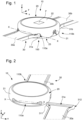
- FIG. 1 illustrates a first perspective view of an exemplary embodiment of a portable object 10 according to the invention.
- This portable object 10 here takes the form of a timepiece, such as a wristwatch intended to be worn on the user's wrist. It will also be understood that the portable object 10 may be, for example, a pedometer, a heart rate monitor, or any other portable object intended to be worn via a bracelet, for example on the wrist.
- FIG. 2 illustrates a second perspective view of the exemplary embodiment of the portable object 10 according to the invention, in which a bracelet strand is shown not fitted into the caseband.
- the portable object 10 comprises a housing 20, intended to receive for example a clockwork movement (not shown here for reasons of clarity).
- the clockwork movement carries and drives means for displaying information, for example the current time.
- the case 20 consists of a caseband 21 closed by a bottom 23 in the lower part and by a crystal 22 in the upper part.
- the case 20 may also include a bezel (not shown) mounted on the caseband 21 and capable of carrying the crystal 22, the bezel being able to be rotatable or not.
- the box 20 defines a main plane P visible, for example, on the figure 1 , with transverse axis x and longitudinal axis y.
- the axis z extends perpendicular to the plane P, and defines the axis of the thickness of the case 20.
- the plane P is advantageously parallel to the flat part of a plate that the watch movement comprises.
- the transverse axis x is parallel to the 3 a.m.-9 a.m. time axis and the longitudinal axis y is parallel to the 6 a.m.-12 p.m. time axis.
- the housing 20 illustrated as an example is of generally circular shape. However, the housing 20 may have other known embodiments without departing from the context of the invention.
- the portable object 10 also comprises a flexible, removable bracelet 30, the two ends of which are intended to be removably coupled to the middle 21 of the case 20, via a fastening system 100.
- the fastening system 100 makes it possible to secure the bracelet 30 to the case 20, to lock the latter in position, and to make easy interchangeability of the bracelet 30 possible, without the use of tools.
- the fastening system 100 makes it possible to achieve a viscoelastic deformation fitting of the bracelet 30, in a reversible manner. Consequently, the fastening system 100 according to the invention is particularly advantageous in contrast to a system by irreversible elastic fitting, requiring the destruction or deterioration of at least one of the elements constituting the fastening system during the disassembly of the bracelet 30 from the case 20.
- the fastening system 100 is an alternative embodiment to an elastic fitting type fastening system.
- a viscoelastic deformation fastening system makes it possible in particular to simplify the production of such a fastening system, in particular by using the viscoelastic deformation properties of the bracelet.
- the bracelet 30 is simpler to design and manufacture.
- the bracelet 30 is in the form of two strands 30a, 30b connected to each other by a closing device (not shown), for example a clasp, a folding buckle or any other ad-hoc element making it possible to perform this function of attaching the two strands 30a, 30b of the bracelet 30 around the user's wrist.
- a closing device for example a clasp, a folding buckle or any other ad-hoc element making it possible to perform this function of attaching the two strands 30a, 30b of the bracelet 30 around the user's wrist.
- the middle 21 comprises two longitudinal cavities 110a, 110b configured to receive the end of each strand 30a, 30b of the bracelet 30, and more particularly attachment heads 31a, 31b forming the ends of each strand 30a, 30b of the bracelet 30.
- a first longitudinal cavity 110a is shown more particularly in FIG. figure 2 .
- the longitudinal cavities 110a, 110b are provided in the middle 21 and advantageously replace the fixing horns commonly used to secure the bracelet 30.
- the longitudinal cavities 110a, 110b cooperate with the attachment heads 31a, 31b of the strands 30a, 30b of the bracelet 30 to form the fixing system 100 of the bracelet 30.
- the middle 21 of the case 20 according to the invention does not include any projecting element for fixing the bracelet 30.
- the manufacture of the case 20 can be carried out entirely in an automated manner.
- the longitudinal cavities 110a, 110b are made at the level of two fixing portions, opposite one another, located on either side of a dial (not shown), and advantageously located at 6 o'clock and 12 o'clock.
- the longitudinal cavities 110a, 110b extend over two circular segments of the caseband 21 located at 6 o'clock and 12 o'clock.
- the longitudinal cavities 110a, 110b form slides extending along a longitudinal axis forming a sliding axis X-X, parallel to the transverse axis x of the housing 20.
- the longitudinal cavities 110a, 110b are configured to receive the attachment heads 31a, 31b of the strands 30a, 30b of the bracelet 30 and to provide translational guidance of the attachment heads 31a, 31b, along of the sliding axis XX, when fitting or removing the bracelet 30.
- the strands 30a, 30b are mounted on the middle 21 by sliding the attachment heads 31a, 31b into the longitudinal cavities 110a, 110b of the middle 21.
- the longitudinal cavities 110a, 110b are open-ended, that is to say they are open at a first end and a second end, such that it is possible to insert and remove the bracelet 30 by sliding both by the first end and by the second end of the longitudinal cavities 110a, 110b, that is to say by the end located on the crown side (3 o'clock side) or by the end located on the side opposite the crown (9 o'clock side).
- the attachment heads 31a, 31b of the strands 30a, 30b have a complementary shape and are adapted to be housed in the longitudinal cavities 110a, 110b and to cooperate by rectilinear sliding, along the sliding axis X-X, in the longitudinal cavities 110a, 110b.
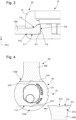
- FIG. 3 represents a section of a portion of the wristwatch 10, along the plane y, z allowing the illustration of the cross section of the longitudinal cavities 110a, 110b and of the attachment heads 31a, 31b locked in the longitudinal cavities 110a, 110b.
- the longitudinal cavities 110a, 110b and the attachment heads 31a, 31b have a section substantially in the shape of a hook.
- the longitudinal cavities 110a, 110b have a lower surface 111 delimiting the lower portion of the cavity, a bottom 112 and an upper surface 113 delimiting the upper portion of the cavity.
- the longitudinal cavities 110a, 110b have an undercut portion making it possible to block the movements of the bracelet with the exception of those of translation along the axis. sliding XX, corresponding to the longitudinal axis of the longitudinal cavities 110a, 110b.
- an undercut portion is provided at the upper surface 113 of the longitudinal cavity 110a, 110b, the lower surface 111 being flat.
- an undercut portion may be provided at the lower surface 111 of the longitudinal cavity 110a, 110b, the upper surface 113 being flat.
- the lower surface 111 and the upper surface 113 of the longitudinal cavity 110a, 110b may have an undercut portion.
- Each attachment head 31a, 31b has an end bead 311 forming the free end of the attachment head 31a, 31b, the end bead 311 having an end surface 312 intended to be positioned opposite or in contact with the bottom 112 of the longitudinal cavity 110a, 110b.
- the end bead 311 has an excess thickness of material compared to the strand 30a, 30b of the bracelet 30.
- Such a shape advantageously allows a translation of the strand 30a, 30b in the corresponding longitudinal cavity 110a, 110b by sliding along the axis X-X, while blocking the other degrees of freedom by the presence of the end bead 311 of material at the end of the attachment head 31a, 31b forming an excess thickness of material relative to the strand 30a, 30b.
- the bead 311 has a shape adapted to cooperate with the undercut portion of the longitudinal cavity 110a, 110b and to form means for holding the bracelet 30.
- the longitudinal cavities 110a, 110b and the heads Additional hooks can have a circular, L-shaped, T-shaped, C-shaped, etc. section.
- the fixing system 100 further comprises viscoelastic fitting means making it possible to secure and lock the axial movement of each strand 30a, 30b in the longitudinal cavities 110a, 110b of the middle part 21, to lock the position of each strand 30a, 30b in a so-called locking position.
- the viscoelastic fitting means are configured to achieve reversible viscoelastic fitting of the attachment heads 31a, 31b of the strands 30a, 30b on the middle 21, by viscoelastic deformation of the attachment heads 31a, 31b, and more particularly of the end beads 311.
- At least the end beads 311 of the attachment heads 31a, 31b are made of a material allowing viscoelastic deformation during insertion of the strands 30a, 30b into the housing 20.
- the viscoelastic fitting means comprise a locking protuberance 210, such as for example a stud or a finger.
- the locking protuberance 210 is advantageously centered longitudinally in each longitudinal cavity 110a, 110b, relative to the sliding axis X-X. However, other positions of the locking protuberance 210 are also envisaged.
- FIG 4 represents a section of the portable object 10 illustrated in the figure 2 according to a median plane of the housing parallel to a plane x, y, making it possible to illustrate the median section of the longitudinal cavities 110a, 110b and the attachment heads 31a, 31b, and in particular the locking protuberance 210 formed inside the longitudinal cavities 110a, 110b.
- the locking protrusion 210 is provided at the bottom 112 of the longitudinal cavity 110a, 110b, and projects relative to the bottom 112, so as to form an obstacle to the assembly of the strands 30a, 30b of the bracelet 30.
- the locking protrusion 210 is rigid.
- the locking protuberance 210 is integral with the case 21.
- the locking protrusion 210 is configured to cooperate with the end surface 312 of the end bead 311 of the attachment heads 31a, 31b, and to deform, in a viscoelastic manner, the end bead 311 during the assembly of the bracelet 30.
- the user must go against a certain assembly resistance due to the efforts necessary to ensure a viscoelastic deformation of the end bead 311 sufficient to ensure the passage of the locking protrusion 210 during the insertion of the bracelet 30 into the longitudinal cavity 110a, 110b.
- a housing 213 is provided at the end surface 312 of the bead 311 of the attachment heads 31a, 31b.
- the housing 213 is configured to receive the locking protuberance 210 and to form blocking means for blocking the axial movement of the strand 30a, 30b in the longitudinal cavity 110a, 110b.
- the housing 213 has a shape complementary to the shape of the locking protuberance 210.
- the locking protrusion 210 cooperates with the housing 213 to form the viscoelastic fitting means of the bracelet 30 and to lock the axial movement of the attachment head 31a, 31b.
- the user To disassemble the bracelet 30, the user must generate sufficient force to remove the locking protrusion 210 from the housing 213 and to deform the end bead 311 of the attachment heads 31a, 31b again.
- the locking protuberance 210 and the complementary housing 213 having clearance angles or even curvilinear shapes at the contact surfaces to facilitate the assembly and disassembly of the bracelet 30.
- the viscoelastic casing means according to the invention are configured to deform the end beads 311 of the attachment heads 31a, 31b by compressing the material in the direction of the bracelet 30, and more particularly of the strands 30a, 30b, substantially along the longitudinal axis y of the case 20.
- the attachment heads 31a, 31b of each strand 30a, 30b of the bracelet 30 are made of a more flexible material than the middle 21 of the case 20 so as to allow the deformation of the end beads 311 of the attachment heads 31a, 31b during assembly of the bracelet 30.
- At least the end bead 311 of the attachment heads 31a, 31b of the bracelet 30 is made of thermoplastic elastomer, of the TPV (for ThermoPlastic Vulcanizate in English), TPU (for thermoplastic polyurethane in English), TPE (for thermoplastic elastomer in English) or TPO (for thermoplastic polyolefin in English).
- TPV for ThermoPlastic Vulcanizate in English
- TPU for thermoplastic polyurethane in English
- TPE for thermoplastic elastomer in English
- TPO thermoplastic polyolefin in English
- at least the end bead 311 of the attachment heads 31a, 31b can be made of Opti-Flex TM .
- the attachment heads 31a, 31b of the bracelet 30 can be made of a material identical to or different from the end beads 311, with viscoelastic characteristics, of identical or different hardness.
- the strands 30a, 30b may be made of a material identical to or different from the attachment heads 31a, 31b of the bracelet 30, with viscoelastic characteristics, of identical or different hardness.
- the case 21 is made of metal or polymer.
- the case 21 is made of polymer thermoplastic.
- the case 21 can be made of polyamide 11, also called polyundecanamide or nylon 11.
- the case 21 is advantageously a single-piece case. However, it is also envisaged to produce a case assembled from several parts manufactured separately.
- the polymer case is a single-piece case made by injection.
- the assembly of the bracelet 30 on the middle 21 of the case 20 is carried out in the following manner.
- the Figures 4 to 6 allow to illustrate different phases of the assembly.
- each strand 30a, 30b is introduced into a longitudinal cavity 110a, 110b of the middle 21.
- the longitudinal cavities 110a, 110b being symmetrical, a mounting of the bracelet 30 can be carried out indifferently by a first end or by a second end of the longitudinal cavities 110a, 110b, that is to say by the end located on the crown side or by the end on the opposite side.
- each strand 30a, 30b is then slid into a longitudinal cavity 110a, 110b along the sliding axis XX of the longitudinal cavity 110a, 110b, in the chosen mounting direction, for example in the direction indicated on the figure 5 .
- the user When inserting the strand 30a, 30b, and when the locking protrusion 210 comes into contact with a lateral end of the end bead 311, the user must provide an effort to viscoelastically deform the portion of the end bead 311 facing the locking protrusion 210, so as to allow the strand 30a, 30b to slide in the longitudinal cavity 110a, 110b until the locking protrusion 210 reaches the housing 213 to ensure a locking of the bracelet 30 by viscoelastic response of the material at the level of the bead 311 returning to its initial shape.
- the user To unlock the bracelet 30 and to disassemble it, the user must provide sufficient force to remove the locking protuberance 210 from the housing 213 and again deform the end bead of the attachment heads 31a, 31b, and in particular the portion of the end bead 311 opposite the locking protuberance 210.
- the end bead 311 is made of deformable material, the thickness of the end bead 311 and the hardness must be determined to prevent the bracelet 30 from being able to be extracted from the longitudinal cavity 110a, 110b by the user by exerting a tensile force on the bracelet 30 in the longitudinal direction of the case 20 by excessively deforming the end bead 311.
- a sufficient thickness it will be ensured that the uncoupling of the bracelet 30 by exerting a tensile force on the strands 30a, 30b is not possible for the user.
- the attachment heads 31a, 31b, and more particularly the end beads 311 have dimensions slightly greater than the dimensions of the longitudinal cavities 110a, 110b.
- an additional deformation is imposed on the attachment heads during the insertion of the strands 30a, 30b.
- Such an embodiment variant makes it possible in particular to increase the force required for fitting and removing the bracelet by sliding.
- the case and the system for attaching a bracelet to the case according to the invention make it possible to greatly facilitate the process for producing the case, since the latter is devoid of attachment lugs and is entirely symmetrical.
- the manufacture of the case and the bracelet can be automated.
- the manufacturing costs of such an assembly and such a portable object are consequently reduced, in particular by the absence of a reworking operation at the case level and by the absence of use of additional elements, such as bars, for attaching the bracelet to the case.
- the fastening system according to the invention advantageously makes it possible to avoid the use of additional or intermediate parts between the bracelet and the middle of the case, such as bars, elastic clips, etc., or the need to use tools (whether specific or commonly used) for securing and/or disassembling the bracelet.
- the fastening system according to the invention makes it possible to simplify the interchangeability of the bracelets, which makes it possible to easily renew the bracelet in the event of wear, or to modify the aesthetics, with simple handling, without the use of tools and without damaging one of the elements of the fastening system when disassembling the bracelet.
Landscapes
- Physics & Mathematics (AREA)
- General Physics & Mathematics (AREA)
- Adornments (AREA)
- Purses, Travelling Bags, Baskets, Or Suitcases (AREA)
- Clamps And Clips (AREA)
Claims (13)
- Tragbarer Gegenstand (10), der eine Schale (20), die einen Mittelteil (21) aufweist, ein Armband (30) und ein Befestigungssystem (100) umfasst, um jedes Ende des Armbands (30) abnehmbar am Mittelteil (21) festzumachen, wobei der Mittelteil (21) zwei längliche Hohlräume (110a, 110b) umfasst, die so konfiguriert sind, dass sie eine Gleitschiene bilden, wobei jedes Ende des Armbands (30) einen Einhängekopf (31a, 31b) umfasst, der von komplementärer Form und so konfiguriert ist, dass er durch Gleiten mit einem der länglichen Hohlräume (110a, 110b) zusammenwirkt, um das Befestigungssystem (100) zu bilden, wobei der Einhängekopf (31a, 31b) einen Endwulst (311) aus viskoelastischem Material umfasst, wobei der tragbare Gegenstand (10) dadurch gekennzeichnet ist, dass das Befestigungssystem (100) viskoelastische Einschalmittel umfasst, um die axiale Bewegung des Einhängekopfes (31a, 31b) im Inneren des länglichen Hohlraums (110a, 110b) durch viskoelastische Reaktion des Endwulstes (311) zu verriegeln, wobei die viskoelastischen Einschalmittel durch das Zusammenwirken eines starren Verriegelungsvorsprungs (210) gebildet werden, der in jedem der länglichen Hohlräume (110a, 110b) ausgestaltet und so konfiguriert ist, dass er den Endwulst (311) aus viskoelastischem Material beim Einfügen des Armbands (30) verformt, wobei der Verriegelungsvorsprung (210) so konfiguriert ist, dass er sich in eine Aufnahme (213) einfügt, die im Bereich des Endwulstes (311) aus viskoelastischem Material ausgestaltet ist, um die axiale Bewegung des Einhängekopfs (31a, 31b) zu verriegeln.
- Tragbarer Gegenstand (10) nach dem vorstehenden Anspruch, dadurch gekennzeichnet, dass der Endwulst (311) aus viskoelastischem Material ein Endabschnitt der Einhängeköpfe (31a, 31b) ist.
- Tragbarer Gegenstand (10) nach einem der vorstehenden Ansprüche, dadurch gekennzeichnet, dass der Endwulst (311) aus viskoelastischem Material einen Endwulst bildet.
- Tragbarer Gegenstand (10) nach einem der vorstehenden Ansprüche, dadurch gekennzeichnet, dass der Endwulst (311) aus viskoelastischem Material aus thermoplastischem Elastomer ist.
- Tragbarer Gegenstand (10) nach einem der vorstehenden Ansprüche, dadurch gekennzeichnet, dass der Einhängekopf (31a, 31b) jedes Endes des Armbands (30) aus thermoplastischem Elastomer ist.
- Tragbarer Gegenstand (10) nach einem der vorstehenden Ansprüche, dadurch gekennzeichnet, dass die Aufnahme (213) in einem zentralen Bereich des Endwulstes (311) aus viskoelastischem Material ausgestaltet ist, und dass der Verriegelungsvorsprung (210) in Längsrichtung im länglichen Hohlraum (110a, 110b) zentriert ist.
- Tragbarer Gegenstand (10) nach einem der vorstehenden Ansprüche, dadurch gekennzeichnet, dass das Armband (30) zwei Stränge (30a, 30b) umfasst, wobei jeder Strang einen Einhängekopf (31a, 31b) umfasst, der das Ende des Stranges (30a, 30b) bildet, und dass der Einhängekopf (31a, 31b) einstückig mit dem Strang (30a, 30b) des Armbands (30) ausgebildet ist.
- Tragbarer Gegenstand (10) nach einem der vorstehenden Ansprüche, dadurch gekennzeichnet, dass der Verriegelungsvorsprung (210) einstückig mit dem Mittelteil (21) ausgebildet ist.
- Tragbarer Gegenstand (10) nach einem der vorstehenden Ansprüche, dadurch gekennzeichnet, dass der Mittelteil (21) aus Thermoplast und vorzugsweise aus Polyamid 11 ist.
- Tragbarer Gegenstand (10) nach einem der vorstehenden Ansprüche, dadurch gekennzeichnet, dass der Einhängekopf (31a, 31b) Abmessungen aufweist, die größer sind als die Abmessungen des länglichen Hohlraums (110a, 110b).
- Tragbarer Gegenstand (10) nach einem der vorstehenden Ansprüche, dadurch gekennzeichnet, dass das Befestigungssystem (100) so konfiguriert ist, dass es das unterschiedslose Anbringen und Abnehmen des Armbands (30) über ein erstes Ende oder ein zweites Ende des länglichen Hohlraums (110a, 110b) ermöglicht.
- Tragbarer Gegenstand (10) nach einem der vorstehenden Ansprüche, dadurch gekennzeichnet, dass sich die länglichen Hohlräume (110a, 110b) an zwei Kreissegmenten des Mittelteils (21) erstrecken, die sich bei 6 Uhr und 12 Uhr befinden.
- Tragbarer Gegenstand (10) nach einem der vorstehenden Ansprüche, dadurch gekennzeichnet, dass der tragbare Gegenstand eine Armbanduhr ist.
Priority Applications (7)
| Application Number | Priority Date | Filing Date | Title |
|---|---|---|---|
| EP21216079.0A EP4197387B1 (de) | 2021-12-20 | 2021-12-20 | Tragbarer gegenstand mit einem gehäuse, einem abnehmbaren armband und einem system zur befestigung des armbands am gehäuse |
| US17/823,178 US12471682B2 (en) | 2021-12-20 | 2022-08-30 | Portable object comprising a case, a removable bracelet and a system for attaching the bracelet to the case |
| JP2022142729A JP7559019B2 (ja) | 2021-12-20 | 2022-09-08 | ケースと、取り外し可能なブレスレットと、及びブレスレットをケースに取り付けるシステムとを備える携行可能な物 |
| KR1020220128111A KR20230094121A (ko) | 2021-12-20 | 2022-10-06 | 케이스, 제거가능한 팔찌 및 케이스에 팔찌를 부착하기 위한 시스템을 포함하는 휴대용 물체 |
| CN202211302800.XA CN116268726A (zh) | 2021-12-20 | 2022-10-24 | 可佩戴物体 |
| CN202222805086.8U CN218483915U (zh) | 2021-12-20 | 2022-10-24 | 可佩戴物体 |
| KR1020250033417A KR20250040920A (ko) | 2021-12-20 | 2025-03-14 | 케이스, 제거가능한 팔찌 및 케이스에 팔찌를 부착하기 위한 시스템을 포함하는 휴대용 물체 |
Applications Claiming Priority (1)
| Application Number | Priority Date | Filing Date | Title |
|---|---|---|---|
| EP21216079.0A EP4197387B1 (de) | 2021-12-20 | 2021-12-20 | Tragbarer gegenstand mit einem gehäuse, einem abnehmbaren armband und einem system zur befestigung des armbands am gehäuse |
Publications (2)
| Publication Number | Publication Date |
|---|---|
| EP4197387A1 EP4197387A1 (de) | 2023-06-21 |
| EP4197387B1 true EP4197387B1 (de) | 2024-09-25 |
Family
ID=78957445
Family Applications (1)
| Application Number | Title | Priority Date | Filing Date |
|---|---|---|---|
| EP21216079.0A Active EP4197387B1 (de) | 2021-12-20 | 2021-12-20 | Tragbarer gegenstand mit einem gehäuse, einem abnehmbaren armband und einem system zur befestigung des armbands am gehäuse |
Country Status (5)
| Country | Link |
|---|---|
| US (1) | US12471682B2 (de) |
| EP (1) | EP4197387B1 (de) |
| JP (1) | JP7559019B2 (de) |
| KR (2) | KR20230094121A (de) |
| CN (2) | CN116268726A (de) |
Families Citing this family (2)
| Publication number | Priority date | Publication date | Assignee | Title |
|---|---|---|---|---|
| KR20220126080A (ko) * | 2021-03-08 | 2022-09-15 | 삼성전자주식회사 | 하우징에 연결되는 스트랩 구조 및 이를 포함하는 웨어러블 전자 장치 |
| EP4197387B1 (de) * | 2021-12-20 | 2024-09-25 | ETA SA Manufacture Horlogère Suisse | Tragbarer gegenstand mit einem gehäuse, einem abnehmbaren armband und einem system zur befestigung des armbands am gehäuse |
Citations (1)
| Publication number | Priority date | Publication date | Assignee | Title |
|---|---|---|---|---|
| JP2000253913A (ja) * | 1999-03-11 | 2000-09-19 | Citizen Watch Co Ltd | 時計ケースとバンド並びにバンド駒間の連結構造 |
Family Cites Families (20)
| Publication number | Priority date | Publication date | Assignee | Title |
|---|---|---|---|---|
| US4432655A (en) * | 1982-10-13 | 1984-02-21 | Bulova Watch Company, Inc. | Integrated watch case and bracelet assembly |
| US4664533A (en) * | 1986-10-06 | 1987-05-12 | Bulova Watch Co., Inc. | Watch case and bracelet assembly |
| JPH0682590U (ja) | 1993-05-07 | 1994-11-25 | セイコー電子工業株式会社 | 携帯時計のバンド取付構造 |
| JP2001112517A (ja) | 1999-10-21 | 2001-04-24 | Arii Gosei Kogyosho:Kk | 時計バンドの製造方法 |
| JP5196054B2 (ja) * | 2012-05-29 | 2013-05-15 | カシオ計算機株式会社 | バンド取付構造 |
| US9357817B2 (en) * | 2013-01-31 | 2016-06-07 | Salutron, Inc. | Reversible wrist strap insert and curved cutout for centering wrist strap |
| WO2016016832A2 (en) * | 2014-07-30 | 2016-02-04 | Zero S.A. | Wrist watch |
| US10184506B2 (en) * | 2014-08-11 | 2019-01-22 | Apple Inc. | Captive elements of an attachment system |
| US9894964B2 (en) * | 2014-08-11 | 2018-02-20 | Apple Inc. | Consumer product attachment systems having a locking assembly |
| CN106539207B (zh) * | 2016-12-08 | 2018-07-31 | 歌尔科技有限公司 | 一种穿戴设备的表带连接结构 |
| US10418693B2 (en) * | 2017-04-11 | 2019-09-17 | Fitbit, Inc. | Band latch mechanism and housing with integrated antenna |
| US10327520B1 (en) * | 2017-08-17 | 2019-06-25 | Apple Inc. | Attachment system for watchband |
| EP3572209B1 (de) | 2018-05-24 | 2021-12-29 | The Swatch Group Research and Development Ltd | Verkleidungskomponente aus verbundmaterial, und ihr herstellungsverfahren |
| CN208798753U (zh) * | 2018-07-13 | 2019-04-30 | 韩东 | 一种智能手表 |
| US11241068B2 (en) * | 2019-04-15 | 2022-02-08 | Apple Inc. | Watch band with braided strands |
| US11611372B1 (en) * | 2020-03-13 | 2023-03-21 | Apple Inc. | Band identifier system for wearable devices |
| KR20250023607A (ko) * | 2020-05-13 | 2025-02-18 | 애플 인크. | 유리 쉘을 갖는 웨어러블 전자 디바이스 |
| US11803162B2 (en) * | 2020-09-25 | 2023-10-31 | Apple Inc. | Watch with sealed housing and sensor module |
| EP4197387B1 (de) * | 2021-12-20 | 2024-09-25 | ETA SA Manufacture Horlogère Suisse | Tragbarer gegenstand mit einem gehäuse, einem abnehmbaren armband und einem system zur befestigung des armbands am gehäuse |
| EP4197386B1 (de) * | 2021-12-20 | 2024-08-07 | ETA SA Manufacture Horlogère Suisse | Tragbarer gegenstand mit einem gehäuse, einem abnehmbaren armband und einem system zur befestigung des armbands am gehäuse |
-
2021
- 2021-12-20 EP EP21216079.0A patent/EP4197387B1/de active Active
-
2022
- 2022-08-30 US US17/823,178 patent/US12471682B2/en active Active
- 2022-09-08 JP JP2022142729A patent/JP7559019B2/ja active Active
- 2022-10-06 KR KR1020220128111A patent/KR20230094121A/ko not_active Ceased
- 2022-10-24 CN CN202211302800.XA patent/CN116268726A/zh active Pending
- 2022-10-24 CN CN202222805086.8U patent/CN218483915U/zh active Active
-
2025
- 2025-03-14 KR KR1020250033417A patent/KR20250040920A/ko active Pending
Patent Citations (1)
| Publication number | Priority date | Publication date | Assignee | Title |
|---|---|---|---|---|
| JP2000253913A (ja) * | 1999-03-11 | 2000-09-19 | Citizen Watch Co Ltd | 時計ケースとバンド並びにバンド駒間の連結構造 |
Also Published As
| Publication number | Publication date |
|---|---|
| JP2023091726A (ja) | 2023-06-30 |
| KR20230094121A (ko) | 2023-06-27 |
| CN218483915U (zh) | 2023-02-17 |
| KR20250040920A (ko) | 2025-03-25 |
| CN116268726A (zh) | 2023-06-23 |
| EP4197387A1 (de) | 2023-06-21 |
| US20230189943A1 (en) | 2023-06-22 |
| JP7559019B2 (ja) | 2024-10-01 |
| US12471682B2 (en) | 2025-11-18 |
Similar Documents
| Publication | Publication Date | Title |
|---|---|---|
| EP4202571A1 (de) | Tragbarer gegenstand mit einem gehäusemittelteil ohne befestigungshörner und einem abnehmbaren armband | |
| EP4197386B1 (de) | Tragbarer gegenstand mit einem gehäuse, einem abnehmbaren armband und einem system zur befestigung des armbands am gehäuse | |
| EP2322997B1 (de) | Tragbares Objekt mit austauschbarem Armband | |
| EP4197387B1 (de) | Tragbarer gegenstand mit einem gehäuse, einem abnehmbaren armband und einem system zur befestigung des armbands am gehäuse | |
| EP3674815B1 (de) | Armbanduhrengehäuse, das mit einem kreisförmigen ring ausgestattet ist, und armbanduhr sowie montagekit für ein uhrenarmband, das dieses umfasst | |
| EP3502791A1 (de) | Armbanduhrengehäuse mit austauschbarem drehbarem aussenring | |
| EP3958069B1 (de) | Armbanduhrgehäuse, das mit einem verkleidungselement ausgestattet ist | |
| CH704810B1 (fr) | Brin de bracelet flexible. | |
| EP3246765B1 (de) | Zwischen-armband-verbindung für armbanduhr | |
| EP3454136B1 (de) | Armbanduhrengehäuse, armbanduhr und montagekit für eine armbanduhr, die dieses umfasst | |
| CH719278A2 (fr) | Objet portable comportant un boîtier, un bracelet amovible et un système de fixation du bracelet au boîtier. | |
| CH715870A1 (fr) | Système de fixation pour bracelets. | |
| CH719280A2 (fr) | Objet portable comportant un boîtier, un bracelet amovible et un système de fixation du bracelet au boîtier. | |
| CH715003B1 (fr) | Système d'attache d'un bracelet à une boîte de montre. | |
| EP4151116B1 (de) | Befestigungssystem für austauschbares band | |
| CH719310A2 (fr) | Objet portable comportant une carrure dépourvue de cornes de fixation et un bracelet amovible. | |
| WO2021209922A1 (fr) | Système de boucle interchangeable | |
| EP3569090B1 (de) | Befestigungssystem eines armbands an einem armbanduhrgehäuse | |
| EP1785784A2 (de) | Vorrichtung zur Verbindung eines Uhrarmbands | |
| EP4018875A1 (de) | Armband | |
| CH720830A2 (fr) | Dispositif de boucle interchangeable | |
| CH712466A2 (fr) | Maillon de liaison pour bracelet de montre. | |
| CH715154B1 (fr) | Organe de fixation d'un bracelet et montre-bracelet. | |
| EP4473862A1 (de) | Austauschbare schnallenvorrichtung | |
| EP0683993B1 (de) | Anschlussvorrichtung für ein Uhrarmband |
Legal Events
| Date | Code | Title | Description |
|---|---|---|---|
| PUAI | Public reference made under article 153(3) epc to a published international application that has entered the european phase |
Free format text: ORIGINAL CODE: 0009012 |
|
| STAA | Information on the status of an ep patent application or granted ep patent |
Free format text: STATUS: THE APPLICATION HAS BEEN PUBLISHED |
|
| AK | Designated contracting states |
Kind code of ref document: A1 Designated state(s): AL AT BE BG CH CY CZ DE DK EE ES FI FR GB GR HR HU IE IS IT LI LT LU LV MC MK MT NL NO PL PT RO RS SE SI SK SM TR |
|
| P01 | Opt-out of the competence of the unified patent court (upc) registered |
Effective date: 20230701 |
|
| STAA | Information on the status of an ep patent application or granted ep patent |
Free format text: STATUS: REQUEST FOR EXAMINATION WAS MADE |
|
| 17P | Request for examination filed |
Effective date: 20231221 |
|
| RBV | Designated contracting states (corrected) |
Designated state(s): AL AT BE BG CH CY CZ DE DK EE ES FI FR GB GR HR HU IE IS IT LI LT LU LV MC MK MT NL NO PL PT RO RS SE SI SK SM TR |
|
| GRAP | Despatch of communication of intention to grant a patent |
Free format text: ORIGINAL CODE: EPIDOSNIGR1 |
|
| STAA | Information on the status of an ep patent application or granted ep patent |
Free format text: STATUS: GRANT OF PATENT IS INTENDED |
|
| RIC1 | Information provided on ipc code assigned before grant |
Ipc: A44B 11/25 20060101ALI20240411BHEP Ipc: G04B 37/14 20060101ALI20240411BHEP Ipc: A44C 5/14 20060101AFI20240411BHEP |
|
| INTG | Intention to grant announced |
Effective date: 20240513 |
|
| GRAS | Grant fee paid |
Free format text: ORIGINAL CODE: EPIDOSNIGR3 |
|
| GRAA | (expected) grant |
Free format text: ORIGINAL CODE: 0009210 |
|
| STAA | Information on the status of an ep patent application or granted ep patent |
Free format text: STATUS: THE PATENT HAS BEEN GRANTED |
|
| AK | Designated contracting states |
Kind code of ref document: B1 Designated state(s): AL AT BE BG CH CY CZ DE DK EE ES FI FR GB GR HR HU IE IS IT LI LT LU LV MC MK MT NL NO PL PT RO RS SE SI SK SM TR |
|
| REG | Reference to a national code |
Ref country code: GB Ref legal event code: FG4D Free format text: NOT ENGLISH |
|
| RIN1 | Information on inventor provided before grant (corrected) |
Inventor name: SCHLICHTIG, DOHAN Inventor name: MUELLER, ROGER |
|
| REG | Reference to a national code |
Ref country code: CH Ref legal event code: EP |
|
| REG | Reference to a national code |
Ref country code: DE Ref legal event code: R096 Ref document number: 602021019262 Country of ref document: DE |
|
| REG | Reference to a national code |
Ref country code: IE Ref legal event code: FG4D Free format text: LANGUAGE OF EP DOCUMENT: FRENCH |
|
| PGFP | Annual fee paid to national office [announced via postgrant information from national office to epo] |
Ref country code: DE Payment date: 20241121 Year of fee payment: 4 |
|
| REG | Reference to a national code |
Ref country code: LT Ref legal event code: MG9D |
|
| PG25 | Lapsed in a contracting state [announced via postgrant information from national office to epo] |
Ref country code: NO Free format text: LAPSE BECAUSE OF FAILURE TO SUBMIT A TRANSLATION OF THE DESCRIPTION OR TO PAY THE FEE WITHIN THE PRESCRIBED TIME-LIMIT Effective date: 20241225 |
|
| PG25 | Lapsed in a contracting state [announced via postgrant information from national office to epo] |
Ref country code: GR Free format text: LAPSE BECAUSE OF FAILURE TO SUBMIT A TRANSLATION OF THE DESCRIPTION OR TO PAY THE FEE WITHIN THE PRESCRIBED TIME-LIMIT Effective date: 20241226 Ref country code: FI Free format text: LAPSE BECAUSE OF FAILURE TO SUBMIT A TRANSLATION OF THE DESCRIPTION OR TO PAY THE FEE WITHIN THE PRESCRIBED TIME-LIMIT Effective date: 20240925 |
|
| PG25 | Lapsed in a contracting state [announced via postgrant information from national office to epo] |
Ref country code: BG Free format text: LAPSE BECAUSE OF FAILURE TO SUBMIT A TRANSLATION OF THE DESCRIPTION OR TO PAY THE FEE WITHIN THE PRESCRIBED TIME-LIMIT Effective date: 20240925 |
|
| PGFP | Annual fee paid to national office [announced via postgrant information from national office to epo] |
Ref country code: FR Payment date: 20241121 Year of fee payment: 4 |
|
| PG25 | Lapsed in a contracting state [announced via postgrant information from national office to epo] |
Ref country code: LV Free format text: LAPSE BECAUSE OF FAILURE TO SUBMIT A TRANSLATION OF THE DESCRIPTION OR TO PAY THE FEE WITHIN THE PRESCRIBED TIME-LIMIT Effective date: 20240925 |
|
| PG25 | Lapsed in a contracting state [announced via postgrant information from national office to epo] |
Ref country code: RS Free format text: LAPSE BECAUSE OF FAILURE TO SUBMIT A TRANSLATION OF THE DESCRIPTION OR TO PAY THE FEE WITHIN THE PRESCRIBED TIME-LIMIT Effective date: 20241225 |
|
| REG | Reference to a national code |
Ref country code: NL Ref legal event code: MP Effective date: 20240925 |
|
| PG25 | Lapsed in a contracting state [announced via postgrant information from national office to epo] |
Ref country code: RS Free format text: LAPSE BECAUSE OF FAILURE TO SUBMIT A TRANSLATION OF THE DESCRIPTION OR TO PAY THE FEE WITHIN THE PRESCRIBED TIME-LIMIT Effective date: 20241225 Ref country code: NO Free format text: LAPSE BECAUSE OF FAILURE TO SUBMIT A TRANSLATION OF THE DESCRIPTION OR TO PAY THE FEE WITHIN THE PRESCRIBED TIME-LIMIT Effective date: 20241225 Ref country code: LV Free format text: LAPSE BECAUSE OF FAILURE TO SUBMIT A TRANSLATION OF THE DESCRIPTION OR TO PAY THE FEE WITHIN THE PRESCRIBED TIME-LIMIT Effective date: 20240925 Ref country code: GR Free format text: LAPSE BECAUSE OF FAILURE TO SUBMIT A TRANSLATION OF THE DESCRIPTION OR TO PAY THE FEE WITHIN THE PRESCRIBED TIME-LIMIT Effective date: 20241226 Ref country code: FI Free format text: LAPSE BECAUSE OF FAILURE TO SUBMIT A TRANSLATION OF THE DESCRIPTION OR TO PAY THE FEE WITHIN THE PRESCRIBED TIME-LIMIT Effective date: 20240925 Ref country code: BG Free format text: LAPSE BECAUSE OF FAILURE TO SUBMIT A TRANSLATION OF THE DESCRIPTION OR TO PAY THE FEE WITHIN THE PRESCRIBED TIME-LIMIT Effective date: 20240925 |
|
| REG | Reference to a national code |
Ref country code: AT Ref legal event code: MK05 Ref document number: 1725886 Country of ref document: AT Kind code of ref document: T Effective date: 20240925 |
|
| PG25 | Lapsed in a contracting state [announced via postgrant information from national office to epo] |
Ref country code: NL Free format text: LAPSE BECAUSE OF FAILURE TO SUBMIT A TRANSLATION OF THE DESCRIPTION OR TO PAY THE FEE WITHIN THE PRESCRIBED TIME-LIMIT Effective date: 20240925 |
|
| PG25 | Lapsed in a contracting state [announced via postgrant information from national office to epo] |
Ref country code: IS Free format text: LAPSE BECAUSE OF FAILURE TO SUBMIT A TRANSLATION OF THE DESCRIPTION OR TO PAY THE FEE WITHIN THE PRESCRIBED TIME-LIMIT Effective date: 20250125 Ref country code: PT Free format text: LAPSE BECAUSE OF FAILURE TO SUBMIT A TRANSLATION OF THE DESCRIPTION OR TO PAY THE FEE WITHIN THE PRESCRIBED TIME-LIMIT Effective date: 20250127 |
|
| PG25 | Lapsed in a contracting state [announced via postgrant information from national office to epo] |
Ref country code: RO Free format text: LAPSE BECAUSE OF FAILURE TO SUBMIT A TRANSLATION OF THE DESCRIPTION OR TO PAY THE FEE WITHIN THE PRESCRIBED TIME-LIMIT Effective date: 20240925 Ref country code: SM Free format text: LAPSE BECAUSE OF FAILURE TO SUBMIT A TRANSLATION OF THE DESCRIPTION OR TO PAY THE FEE WITHIN THE PRESCRIBED TIME-LIMIT Effective date: 20240925 |
|
| PG25 | Lapsed in a contracting state [announced via postgrant information from national office to epo] |
Ref country code: ES Free format text: LAPSE BECAUSE OF FAILURE TO SUBMIT A TRANSLATION OF THE DESCRIPTION OR TO PAY THE FEE WITHIN THE PRESCRIBED TIME-LIMIT Effective date: 20240925 |
|
| PG25 | Lapsed in a contracting state [announced via postgrant information from national office to epo] |
Ref country code: AT Free format text: LAPSE BECAUSE OF FAILURE TO SUBMIT A TRANSLATION OF THE DESCRIPTION OR TO PAY THE FEE WITHIN THE PRESCRIBED TIME-LIMIT Effective date: 20240925 Ref country code: EE Free format text: LAPSE BECAUSE OF FAILURE TO SUBMIT A TRANSLATION OF THE DESCRIPTION OR TO PAY THE FEE WITHIN THE PRESCRIBED TIME-LIMIT Effective date: 20240925 |
|
| PGFP | Annual fee paid to national office [announced via postgrant information from national office to epo] |
Ref country code: CH Payment date: 20250101 Year of fee payment: 4 |
|
| PG25 | Lapsed in a contracting state [announced via postgrant information from national office to epo] |
Ref country code: CZ Free format text: LAPSE BECAUSE OF FAILURE TO SUBMIT A TRANSLATION OF THE DESCRIPTION OR TO PAY THE FEE WITHIN THE PRESCRIBED TIME-LIMIT Effective date: 20240925 Ref country code: PL Free format text: LAPSE BECAUSE OF FAILURE TO SUBMIT A TRANSLATION OF THE DESCRIPTION OR TO PAY THE FEE WITHIN THE PRESCRIBED TIME-LIMIT Effective date: 20240925 |
|
| PG25 | Lapsed in a contracting state [announced via postgrant information from national office to epo] |
Ref country code: IT Free format text: LAPSE BECAUSE OF FAILURE TO SUBMIT A TRANSLATION OF THE DESCRIPTION OR TO PAY THE FEE WITHIN THE PRESCRIBED TIME-LIMIT Effective date: 20240925 Ref country code: SK Free format text: LAPSE BECAUSE OF FAILURE TO SUBMIT A TRANSLATION OF THE DESCRIPTION OR TO PAY THE FEE WITHIN THE PRESCRIBED TIME-LIMIT Effective date: 20240925 |
|
| REG | Reference to a national code |
Ref country code: DE Ref legal event code: R097 Ref document number: 602021019262 Country of ref document: DE |
|
| PG25 | Lapsed in a contracting state [announced via postgrant information from national office to epo] |
Ref country code: MC Free format text: LAPSE BECAUSE OF FAILURE TO SUBMIT A TRANSLATION OF THE DESCRIPTION OR TO PAY THE FEE WITHIN THE PRESCRIBED TIME-LIMIT Effective date: 20240925 |
|
| PG25 | Lapsed in a contracting state [announced via postgrant information from national office to epo] |
Ref country code: DK Free format text: LAPSE BECAUSE OF FAILURE TO SUBMIT A TRANSLATION OF THE DESCRIPTION OR TO PAY THE FEE WITHIN THE PRESCRIBED TIME-LIMIT Effective date: 20240925 |
|
| PLBE | No opposition filed within time limit |
Free format text: ORIGINAL CODE: 0009261 |
|
| STAA | Information on the status of an ep patent application or granted ep patent |
Free format text: STATUS: NO OPPOSITION FILED WITHIN TIME LIMIT |
|
| PG25 | Lapsed in a contracting state [announced via postgrant information from national office to epo] |
Ref country code: LU Free format text: LAPSE BECAUSE OF NON-PAYMENT OF DUE FEES Effective date: 20241220 |
|
| 26N | No opposition filed |
Effective date: 20250626 |
|
| PG25 | Lapsed in a contracting state [announced via postgrant information from national office to epo] |
Ref country code: SE Free format text: LAPSE BECAUSE OF FAILURE TO SUBMIT A TRANSLATION OF THE DESCRIPTION OR TO PAY THE FEE WITHIN THE PRESCRIBED TIME-LIMIT Effective date: 20240925 |
|
| REG | Reference to a national code |
Ref country code: BE Ref legal event code: MM Effective date: 20241231 |
|
| PG25 | Lapsed in a contracting state [announced via postgrant information from national office to epo] |
Ref country code: BE Free format text: LAPSE BECAUSE OF NON-PAYMENT OF DUE FEES Effective date: 20241231 |
|
| PG25 | Lapsed in a contracting state [announced via postgrant information from national office to epo] |
Ref country code: IE Free format text: LAPSE BECAUSE OF NON-PAYMENT OF DUE FEES Effective date: 20241220 |