EP4196409B1 - Verschluss für einen ausguss in einer dünnwandigen verpackung - Google Patents
Verschluss für einen ausguss in einer dünnwandigen verpackung Download PDFInfo
- Publication number
- EP4196409B1 EP4196409B1 EP21762797.5A EP21762797A EP4196409B1 EP 4196409 B1 EP4196409 B1 EP 4196409B1 EP 21762797 A EP21762797 A EP 21762797A EP 4196409 B1 EP4196409 B1 EP 4196409B1
- Authority
- EP
- European Patent Office
- Prior art keywords
- guarantee
- cap
- spout
- ring
- closure
- Prior art date
- Legal status (The legal status is an assumption and is not a legal conclusion. Google has not performed a legal analysis and makes no representation as to the accuracy of the status listed.)
- Active
Links
Images


Classifications
-
- B—PERFORMING OPERATIONS; TRANSPORTING
- B65—CONVEYING; PACKING; STORING; HANDLING THIN OR FILAMENTARY MATERIAL
- B65D—CONTAINERS FOR STORAGE OR TRANSPORT OF ARTICLES OR MATERIALS, e.g. BAGS, BARRELS, BOTTLES, BOXES, CANS, CARTONS, CRATES, DRUMS, JARS, TANKS, HOPPERS, FORWARDING CONTAINERS; ACCESSORIES, CLOSURES, OR FITTINGS THEREFOR; PACKAGING ELEMENTS; PACKAGES
- B65D41/00—Caps, e.g. crown caps or crown seals, i.e. members having parts arranged for engagement with the external periphery of a neck or wall defining a pouring opening or discharge aperture; Protective cap-like covers for closure members, e.g. decorative covers of metal foil or paper
- B65D41/02—Caps or cap-like covers without lines of weakness, tearing strips, tags, or like opening or removal devices
- B65D41/04—Threaded or like caps or cap-like covers secured by rotation
- B65D41/0485—Threaded or like caps or cap-like covers secured by rotation with means specially adapted for facilitating the operation of opening or closing
-
- B—PERFORMING OPERATIONS; TRANSPORTING
- B65—CONVEYING; PACKING; STORING; HANDLING THIN OR FILAMENTARY MATERIAL
- B65D—CONTAINERS FOR STORAGE OR TRANSPORT OF ARTICLES OR MATERIALS, e.g. BAGS, BARRELS, BOTTLES, BOXES, CANS, CARTONS, CRATES, DRUMS, JARS, TANKS, HOPPERS, FORWARDING CONTAINERS; ACCESSORIES, CLOSURES, OR FITTINGS THEREFOR; PACKAGING ELEMENTS; PACKAGES
- B65D41/00—Caps, e.g. crown caps or crown seals, i.e. members having parts arranged for engagement with the external periphery of a neck or wall defining a pouring opening or discharge aperture; Protective cap-like covers for closure members, e.g. decorative covers of metal foil or paper
- B65D41/32—Caps or cap-like covers with lines of weakness, tearing-strips, tags, or like opening or removal devices, e.g. to facilitate formation of pouring openings
- B65D41/34—Threaded or like caps or cap-like covers provided with tamper elements formed in, or attached to, the closure skirt
- B65D41/3442—Threaded or like caps or cap-like covers provided with tamper elements formed in, or attached to, the closure skirt with rigid bead or projections formed on the tamper element and coacting with bead or projections on the container
- B65D41/3447—Threaded or like caps or cap-like covers provided with tamper elements formed in, or attached to, the closure skirt with rigid bead or projections formed on the tamper element and coacting with bead or projections on the container the tamper element being integrally connected to the closure by means of bridges
-
- B—PERFORMING OPERATIONS; TRANSPORTING
- B65—CONVEYING; PACKING; STORING; HANDLING THIN OR FILAMENTARY MATERIAL
- B65D—CONTAINERS FOR STORAGE OR TRANSPORT OF ARTICLES OR MATERIALS, e.g. BAGS, BARRELS, BOTTLES, BOXES, CANS, CARTONS, CRATES, DRUMS, JARS, TANKS, HOPPERS, FORWARDING CONTAINERS; ACCESSORIES, CLOSURES, OR FITTINGS THEREFOR; PACKAGING ELEMENTS; PACKAGES
- B65D55/00—Accessories for container closures not otherwise provided for
- B65D55/16—Devices preventing loss of removable closure members
-
- B—PERFORMING OPERATIONS; TRANSPORTING
- B65—CONVEYING; PACKING; STORING; HANDLING THIN OR FILAMENTARY MATERIAL
- B65D—CONTAINERS FOR STORAGE OR TRANSPORT OF ARTICLES OR MATERIALS, e.g. BAGS, BARRELS, BOTTLES, BOXES, CANS, CARTONS, CRATES, DRUMS, JARS, TANKS, HOPPERS, FORWARDING CONTAINERS; ACCESSORIES, CLOSURES, OR FITTINGS THEREFOR; PACKAGING ELEMENTS; PACKAGES
- B65D75/00—Packages comprising articles or materials partially or wholly enclosed in strips, sheets, blanks, tubes or webs of flexible sheet material, e.g. in folded wrappers
- B65D75/52—Details
- B65D75/58—Opening or contents-removing devices added or incorporated during package manufacture
- B65D75/5861—Spouts
- B65D75/5872—Non-integral spouts
- B65D75/5883—Non-integral spouts connected to the package at the sealed junction of two package walls
-
- B—PERFORMING OPERATIONS; TRANSPORTING
- B65—CONVEYING; PACKING; STORING; HANDLING THIN OR FILAMENTARY MATERIAL
- B65D—CONTAINERS FOR STORAGE OR TRANSPORT OF ARTICLES OR MATERIALS, e.g. BAGS, BARRELS, BOTTLES, BOXES, CANS, CARTONS, CRATES, DRUMS, JARS, TANKS, HOPPERS, FORWARDING CONTAINERS; ACCESSORIES, CLOSURES, OR FITTINGS THEREFOR; PACKAGING ELEMENTS; PACKAGES
- B65D85/00—Containers, packaging elements or packages, specially adapted for particular articles or materials
- B65D85/70—Containers, packaging elements or packages, specially adapted for particular articles or materials for materials not otherwise provided for
- B65D85/72—Containers, packaging elements or packages, specially adapted for particular articles or materials for materials not otherwise provided for for edible or potable liquids, semiliquids, or plastic or pasty materials
-
- B—PERFORMING OPERATIONS; TRANSPORTING
- B65—CONVEYING; PACKING; STORING; HANDLING THIN OR FILAMENTARY MATERIAL
- B65D—CONTAINERS FOR STORAGE OR TRANSPORT OF ARTICLES OR MATERIALS, e.g. BAGS, BARRELS, BOTTLES, BOXES, CANS, CARTONS, CRATES, DRUMS, JARS, TANKS, HOPPERS, FORWARDING CONTAINERS; ACCESSORIES, CLOSURES, OR FITTINGS THEREFOR; PACKAGING ELEMENTS; PACKAGES
- B65D2401/00—Tamper-indicating means
- B65D2401/15—Tearable part of the closure
- B65D2401/30—Tamper-ring remaining connected to closure after initial removal
-
- B—PERFORMING OPERATIONS; TRANSPORTING
- B65—CONVEYING; PACKING; STORING; HANDLING THIN OR FILAMENTARY MATERIAL
- B65D—CONTAINERS FOR STORAGE OR TRANSPORT OF ARTICLES OR MATERIALS, e.g. BAGS, BARRELS, BOTTLES, BOXES, CANS, CARTONS, CRATES, DRUMS, JARS, TANKS, HOPPERS, FORWARDING CONTAINERS; ACCESSORIES, CLOSURES, OR FITTINGS THEREFOR; PACKAGING ELEMENTS; PACKAGES
- B65D2575/00—Packages comprising articles or materials partially or wholly enclosed in strips, sheets, blanks, tubes or webs of flexible sheet material, e.g. in folded wrappers
- B65D2575/52—Details
- B65D2575/58—Opening or contents-removing devices added or incorporated during package manufacture
- B65D2575/586—Opening or contents-removing devices added or incorporated during package manufacture with means for reclosing
Definitions
- the present invention is in the field of thin-walled packages provided with a spout, usually referred to as a "pouch".
- the present invention refers to a closure for a spout of said package.
- Said packages are primarily used to contain fruit juices, yoghurt, fruit puree, energy drinks, and similar products for children. These packages have become very popular, due to their compact size, great practicality of use, and playful aspect linked to the use of the spout, which attracts the attention of children. Several hundred million units are produced and sold every year.
- spout closures made of plastic, comprise a cap and a guarantee seal, which comprises a guarantee ring joined to the cap by a plurality of breakable bridges. When the cap is unscrewed for the first time, the bridges break, separating the cap from the guarantee ring and making the first opening apparent.
- US 2008/197135 A1 discloses a closure assembly according to the preamble of claim 1.
- the package 1 comprises a pouch 2 for containing the product, comprising a front wall 4 and a rear wall 6, facing each other, made of a flexible, single-layer or multi-layer film.
- the walls 4, 6 are welded together or, in a variant embodiment, sides are provided made of flexible film and welded to the walls 4, 6.
- the package 1 further comprises a spout assembly 10, typically made in one piece of plastic material by injection molding.
- the spout assembly 10 has an internal spout duct 12 extending from a lower end 14a, intended to be contained in the pouch 2, to an upper end 14b in which is found a mouth 16 for dispensing product along a spout axis X.
- the spout assembly 10 comprises a connection portion 20, referred to as a "weld boat,” intended to be hermetically applied to the pouch 2, between the top edges of the walls 4, 6, for example, by welding.
- the connection portion 20 is axially delimited by a first plate 22 orthogonal to the spout axis X.
- the second plate 24 has two opposing straight edges 25', 25", connected by two leading edges 26', 26", which are, for example, arched.
- the spout assembly 10 further comprises a spout 30 extending axially from the second plate 24 and ending with the mouth 16.
- the spout assembly 10 further comprises an engagement plate 26a - 26e, which is orthogonal to the spout axis X and projecting radially outward from the outer side surface of the spout 30.
- the projection of the engagement plate template 26a - 26e along the spout axis X onto the second plate 24 is entirely contained within said second plate 24, so as not to interfere with the movement of the packages along the filling lines.
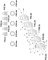
- said engagement plate 26a - 26e has a cross section having various shapes ( Fig. 4a through 4e ): cylindrical circular crown shape; cylindrical circular crown chamfered by straight portions at the straight edges 25', 25" of the second plate 24; grooved with arched edges; grooved with straight edges; cylindrical circular crown chamfered by mixed straight and arched segments.
- the package 1 further comprises a closure 40 applicable to the spout assembly 10.
- the closure 40 comprises a cap assembly 42 and an over-cap 44, which are made separately and joined together.
- the cap assembly 42 comprises a cap 46, having a central cap axis Y and comprising an annular, internally threaded cap wall 48, a cap base 50 which closes the cap wall 48 at one end, and a cap flange 52, radially projecting externally from the cap wall 48, on the other end.
- the cap assembly 42 further comprises a guarantee seal 54 comprising a guarantee ring 56, a guarantee band 58, and a plurality of breakable bridges 60 joining the guarantee ring 56 to the guarantee band 58 and the guarantee band 58 to the cap flange 52.
- the guarantee band 58 which extends between an initial portion 58a and an end portion 58b, is wound about the cap axis Y in a circumferential pattern, whereby, in an unbroken seal configuration, the initial portion 58a is circumferentially opposite the end portion 58b and spaced apart therefrom.
- the guarantee band 58 is also superimposed on the guarantee ring 56, from which it is axially separated by a first separation line 62, along which some bridges 60 are arranged; the cap flange 52 is in turn axially superimposed on the guarantee band 58, from which it is axially separated by a second separation line 64, along which some bridges 60 are arranged.
- the guarantee seal 54 further comprises a first attachment portion 66, which is more resistant than the bridges 60 and joins the guarantee band 58, and in particular the initial portion 58a thereof, to the guarantee ring 56.
- the guarantee seal 54 further comprises a second attachment portion 68, which is more resistant than the bridges 60 and joins the guarantee band 58, and in particular the end portion 58b thereof, to the cap flange 52.
- the guarantee seal 54 comprises a predominantly circumferentially extending breakable segment 70, which joins the initial portion 58a of the band 58 with the end portion 58b.
- the breakable segment 70 is configured to encounter a preferential breakage at the initial portion 58a, whereby the part remaining after the first opening remains attached to the end portion 58b ( Fig. 7a and 7b ).
- the breakable segment 70 has a cross section with decreasing resistance from the end portion 58b to the initial portion 58a.
- the bridges 60 are configured to preferentially break at the guarantee band 58, whereby any residual protrusions remaining after the first opening remain attached to the guarantee ring 56 or cap flange 52, leaving the guarantee band 58 free of protrusions ( Fig. 7a and 7c ).
- the bridges 60 have a cross section with decreasing resistance from the guarantee band 58 toward the guarantee ring 56 or toward the cap flange 52, whereby, at the guarantee ring 56 or the cap flange 52, the cross section is small and particularly weak.
- the first separation line 62 has a fret ( Fig. 8a through 8d ) or wavy circumferential pattern ( Fig. 9a through 9d ), whereby the guarantee band 58 and the guarantee ring 56 interpenetrate axially, forming reliefs and respective indents.
- the guarantee band 58 has at least one axial relief 80, which corresponds to the respective axial indent 82 of the guarantee ring 56; according to a further example, the guarantee ring 56 has at least one axial relief 84 which corresponds to the respective axial indent 86 of the guarantee band 58.
- the reliefs 80 of the guarantee band 58 thrust on the reliefs 84 of the guarantee ring 56, which act as circumferential abutments, dragging the guarantee ring 56 in rotation, thus avoiding the breakage of the bridges 60 between the guarantee band 58 and the guarantee ring 56.
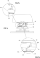
- the over-cap 44 preferably made of plastic material in one piece, for example by injection molding, comprises a shell 90 integral with the cap 46, for example so that it covers, at least partially, the outer surface of the cap wall 48.
- the over-cap 44 further comprises an annular handle 92, radially spaced externally from the shell 90, and spokes 94 that make the handle 92 integral with the shell 90.
- the handle 92 has a handle opening 94 at the top, i.e., on the side of the cap base 50, delimited by an opening edge 96 that surmounts the cap base 50 and is arranged axially spaced therefrom.
- the handle 92 has a lower perimeter edge 98 substantially coplanar with the lower edge of the cap wall 48, below which the cap flange 52 is located.
- the closure 40 is made of plastic material in a single piece, for example by injection molding.
- the shell is integrated with the cap.
- the guarantee ring 56 is at least partially received in the ring seat 100, which is impossible to be pulled out axially without damaging it.
- the guarantee band 58 is located outside of the ring seat 100, above the engagement plate 26a - 26e.
- the guarantee ring 56 is freely rotatable in the ring seat 100; according to a further embodiment, locking means are provided to prevent or limit the free rotation of the guarantee ring 56 in the ring seat 100.
- the breakable segment 70 breaks, as do the bridges 60, so that after unscrewing, the guarantee band 58 takes the form of a strap 58', connected to the guarantee ring 56 by the first attachment portion 66 and to the cap 46, and in particular to the cap flange 52, by the second attachment portion 68 ( Fig. 1a through 1d ).
- the closure 40 although unscrewed from the spout 30, thus remains connected to the spout assembly 10 (open configuration) .
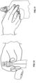
- the guarantee band 58 is configured whereby in the open configuration, the handle 92 may be sufficiently far from the spout 30 so as to be able to place a user's fingers on the extended guarantee band 58, between the spout 30 and the handle 92, whereby the handle 92 is not in the way when using the spout ( Fig. 11 and 12 ).
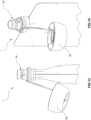
- the guarantee band 58 when the package is in a use configuration in which it is substantially taut and straight, has a length such that the end portion 58b, to which the cap 46, and in particular the cap flange 52, is attached, is below the connection portion 20 of the spout assembly 10 ( Fig. 13 and 14 ). Because the end portion 58b is deformable, the handle 92 may be easily rotated and positioned out of the way.
- the attachment of the guarantee band 58 to the guarantee ring 56 and the cap 46 is configured whereby if the cap is pulled so that it causes a breakage and separation from the spout assembly, such breakage preferably occurs at the attachment between the guarantee band 58 and the guarantee ring 56.
- the resistant cross section of the first attachment portion 66 is smaller than the resistant cross section of the second attachment portion 68 and the resistant cross section of the guarantee band 58 so as to cause preferential breakage in said region ( Fig. 15 and 16 ).
- the closure according to the present invention achieves the aforementioned object, in that it meets the industry requirement of being provided with a guarantee seal, while at the same time allowing the cap and handle to remain fastened to the spout assembly even after the package has been opened and allowing the spout to be used without the cap or handle being in the way.
- the closure assembly is equipped with a guarantee seal, the broken condition of which is particularly apparent.
- the guarantee seal of the present invention allows the user to evaluate the condition of the closure assembly.
- the breakable segment allows the user to easily determine whether the closure assembly has been even partially opened.
- the breakable segment is another visible sign that determines whether the guarantee seal has been breached.
- the breakable segment increases the resistance of the guarantee seal, avoiding the accidental breakage of said seal and the resulting opening of the closure assembly, compromising its conformity.
Landscapes
- Engineering & Computer Science (AREA)
- Mechanical Engineering (AREA)
- Closures For Containers (AREA)
- Bag Frames (AREA)
- Cartons (AREA)
- Laminated Bodies (AREA)
Claims (11)
- Verschlussanordnung für eine Verpackung (1) mit flexiblem dünnwandigem Beutel (2) für die Aufnahme von Fruchtsäften und -püree, Joghurt, Energydrinks und dergleichen, umfassend:- eine Ausgussanordnung (10), die einen Verbindungsabschnitt (12), der geeignet ist, hermetisch auf den Beutel aufgebracht zu werden, und einen Gewindeausguss (30) umfasst, der außen mit einem Ringsitz (100) versehen ist;- einen Verschluss (40), der eine Kappenanordnung (42) umfasst, umfassenda) eine Kappe (46), die mit dem Ausguss (30) verschraubbar ist;b) ein Garantiesiegel (54) zum Hervorheben der ersten Öffnung des Verschlusses (40), umfassend:i) einen Garantiering (56), der zumindest teilweise in dem Ringsitz (100) des Ausgusses (30) aufgenommen ist;ii) ein ringförmiges Garantieband (58), das in einer Konfiguration mit ungebrochenem Siegel den Garantiering (56) axial überlappt und von dem Garantiering (56) durch eine erste Trennlinie (62) und von der Kappe (46) durch eine zweite Trennlinie (64) getrennt ist;iii) eine Mehrzahl von brechbaren Brücken (60), die in der Konfiguration mit ungebrochenem Siegel den Garantiering (56) mit dem Garantieband (58) und das Garantieband (58) mit der Kappe (46) verbinden;iv) einen ersten Anbringungsabschnitt (66), der widerstandsfähiger ist als die Brücken (60) und das Garantieband (58) mit dem Garantiering (56) verbindet, und einen zweiten Anbringungsabschnitt (68), der widerstandsfähiger ist als die Brücken (60) und das Garantieband (58) mit der Kappe (46) verbindet;- wobei in einer offenen Konfiguration des Verschlusses (40), in der die Kappe (46) abgeschraubt ist und die Brücken (60) gebrochen sind, das Garantieband (58) einen Riemen (58') bildet, der die Kappe (46) an dem Garantiering (56) befestigt hält;- wobei das Garantieband (58) eine solche Länge aufweist, dass in einer Gebrauchskonfiguration, in der das Garantieband (58) gestreckt ist, der zweite Anbringungsabschnitt (68) axial unterhalb des Verbindungsabschnitts (12) der Ausgussanordnung (10) angeordnet ist;wobei sich das Garantieband (58) zwischen einem Anfangsabschnitt (58a) und einem Endabschnitt (58b) erstreckt und in der Konfiguration mit ungebrochenem Siegel der Anfangsabschnitt (58a) in Umfangsrichtung zu dem bzw. an den Endabschnitt (58b) benachbart ist bzw. angrenzt und von diesem beabstandet ist;dadurch gekennzeichnet, dass das Garantiesiegel (54) ein sich überwiegend in Umfangsrichtung erstreckendes brechbares Segment (70) umfasst, das den Anfangsabschnitt (58a) des Garantiebands (58) mit dem Endabschnitt (58b) verbindet, wobei in der offenen Konfiguration das brechbare Segment (70) gebrochen ist.
- Verschlussanordnung nach Anspruch 1, wobei der erste Anbringungsabschnitt (66) an dem Anfangsabschnitt (58a) ist und der zweite Anbringungsabschnitt (68) an dem Endabschnitt (58b) ist.
- Verschlussanordnung nach einem der vorhergehenden Ansprüche, wobei das brechbare Segment (70) so bemessen ist, dass es einem bevorzugten Bruch an dem Anfangsabschnitt (58a) unterliegt.
- Verschlussanordnung nach einem der vorhergehenden Ansprüche, wobei die Brücken (60) so bemessen sind, dass sie einem bevorzugten Bruch an dem Garantieband (58) unterliegen.
- Verschlussanordnung nach einem der vorhergehenden Ansprüche, wobei die erste Trennlinie (62) ein Mäander- oder Wellenmuster in Umfangsrichtung aufweist, um mindestens ein Relief (80) des Garantiebands (58) zu bilden, das in einer ersten Schraubkonfiguration auf ein jeweiliges Relief (84) des Garantierings (56) drückt, wodurch der Garantiering (56) in Drehung versetzt wird.
- Verschlussanordnung nach einem der vorhergehenden Ansprüche, wobei der Garantiering (56) in dem Ringsitz (100) frei drehbar ist.
- Verschlussanordnung nach einem der vorhergehenden Ansprüche, umfassend Verriegelungsmittel, welche die freie Drehung des Garantierings (56) in dem Ringsitz (100) verhindern oder begrenzen.
- Verschlussanordnung nach einem der vorhergehenden Ansprüche, wobei der erste Anbringungsabschnitt (66) so bemessen ist, dass wenn an der Kappe (46) gezogen wird, um einen Bruch und eine Trennung von der Ausgussanordnung (10) zu verursachen, ein solcher Bruch an dem ersten Anbringungsabschnitt (66) auftritt.
- Verschlussanordnung nach einem der vorhergehenden Ansprüche, wobei der Verschluss (40) eine Überkappe (44), die eine mit der Kappe (46) einstückige bzw. integrale Schale (90) und einen ringförmigen Griff (92) umfasst, der radial außen von der Schale (90) beabstandet ist, und Speichen (94) umfasst, die den Griff (92) einstückig bzw. integral mit der Schale (90) machen.
- Verschlussanordnung nach einem der vorhergehenden Ansprüche, wobei der Ringsitz (100) durch eine zweite Platte (24) und durch eine Eingriffsplatte (26a - 26e) begrenzt ist, wodurch die Projektion der Form der Eingriffsplatte (26a - 26e) entlang der Ausgussachse (X) auf die zweite Platte (24) vollständig in der zweiten Platte (24) enthalten ist.
- Verpackung (1), umfassend:- einen dünnwandigen flexiblen Beutel (2); und- eine Verschlussanordnung nach einem der vorhergehenden Ansprüche, wobei die Ausgussanordnung (10) der Verschlussanordnung hermetisch auf den Beutel (2) aufgebracht ist.
Applications Claiming Priority (2)
| Application Number | Priority Date | Filing Date | Title |
|---|---|---|---|
| IT102020000019939A IT202000019939A1 (it) | 2020-08-11 | 2020-08-11 | Chiusura per una cannuccia di un imballo a pareti sottili |
| PCT/IB2021/057266 WO2022034459A1 (en) | 2020-08-11 | 2021-08-06 | Closure for a spout in a thin-walled package |
Publications (2)
| Publication Number | Publication Date |
|---|---|
| EP4196409A1 EP4196409A1 (de) | 2023-06-21 |
| EP4196409B1 true EP4196409B1 (de) | 2024-12-25 |
Family
ID=72886087
Family Applications (1)
| Application Number | Title | Priority Date | Filing Date |
|---|---|---|---|
| EP21762797.5A Active EP4196409B1 (de) | 2020-08-11 | 2021-08-06 | Verschluss für einen ausguss in einer dünnwandigen verpackung |
Country Status (9)
| Country | Link |
|---|---|
| US (1) | US20230303294A1 (de) |
| EP (1) | EP4196409B1 (de) |
| BR (1) | BR112023002482A2 (de) |
| CL (1) | CL2023000403A1 (de) |
| CR (1) | CR20230080A (de) |
| ES (1) | ES3008009T3 (de) |
| IT (1) | IT202000019939A1 (de) |
| MX (1) | MX2023001645A (de) |
| WO (1) | WO2022034459A1 (de) |
Families Citing this family (2)
| Publication number | Priority date | Publication date | Assignee | Title |
|---|---|---|---|---|
| IT202200002990A1 (it) | 2022-02-17 | 2023-08-17 | Guala Pack Spa | Chiusura per una cannuccia di un imballo a pareti sottili |
| DE102022111669A1 (de) * | 2022-05-10 | 2023-11-16 | Georg Menshen Gmbh & Co. Kg | Ausgießvorrichtung |
Family Cites Families (80)
| Publication number | Priority date | Publication date | Assignee | Title |
|---|---|---|---|---|
| US2961119A (en) * | 1957-11-25 | 1960-11-22 | Charles F Leach | Closure devices |
| US4343408A (en) * | 1980-04-21 | 1982-08-10 | General Kap (P.R.) Corporation | Tamper-evident plastic closure |
| US4380299A (en) * | 1980-09-10 | 1983-04-19 | Precision Plastic Products Corporation | Tamper proof closure |
| US4339056A (en) * | 1980-11-03 | 1982-07-13 | Berkstresser Jr Harold | Lid tidy |
| US4550843A (en) * | 1982-12-14 | 1985-11-05 | Maxcap, Inc. | Bottle caps |
| US4549667A (en) * | 1984-03-15 | 1985-10-29 | Owens-Illinois, Inc. | Tamper indicating package |
| US4567993A (en) * | 1984-07-06 | 1986-02-04 | Aluminum Company Of America | Tamper-evident closure |
| US4909404A (en) * | 1984-12-10 | 1990-03-20 | Oleg Rozenberg | Tamper-evident closures |
| DE3677102D1 (de) * | 1985-07-31 | 1991-02-28 | A C I Australia Ltd | Garantieverschluss fuer behaelter. |
| US4904435A (en) * | 1985-12-19 | 1990-02-27 | The West Company | Method for making tamper-evident container closure |
| US4744480A (en) * | 1985-12-19 | 1988-05-17 | The West Company | Tamper-evident container-closure |
| GB2191766A (en) * | 1986-06-17 | 1987-12-23 | Grace W R & Co | Screw container with tamper-evident feature |
| US4753358A (en) * | 1987-03-02 | 1988-06-28 | Promega Corporation | Vial cap coupling device |
| US4741447A (en) * | 1987-04-27 | 1988-05-03 | American National Can Company | Linerless cap closure |
| US4878589A (en) * | 1987-04-27 | 1989-11-07 | American National Can Company | Linerless cap closure |
| US4923073A (en) * | 1989-01-30 | 1990-05-08 | H-C Industries, Inc. | Tamper-indicating plastic closure |
| US4989740A (en) * | 1990-03-07 | 1991-02-05 | Continental White Cap, Inc. | Composite cap including tamper indicating feature |
| US5097974A (en) * | 1991-02-07 | 1992-03-24 | Oleg Rozenberg | Tamper-evident closures |
| US5215204A (en) * | 1992-03-09 | 1993-06-01 | Creative Packaging Corp. | Tamper evident closure with hinged band |
| US5246125A (en) * | 1992-05-04 | 1993-09-21 | Sunbeam Plastics Corporation | Tamper indicating closure with attached tamper indicating band |
| CA2107041A1 (en) * | 1993-02-09 | 1994-08-10 | Jose Carvalheiro | Stopper device for recipient |
| US6279774B1 (en) * | 1996-08-30 | 2001-08-28 | Southcorp Packaging Usa | Cover locking mechanism |
| US20010030164A1 (en) * | 1996-10-09 | 2001-10-18 | Romeo Corvaglia | Tamper-proof bottle cap |
| US5755346A (en) * | 1996-11-04 | 1998-05-26 | Phoenix Closures, Inc. | Tamper indicating closure with dual-camming projection band |
| US5848686A (en) * | 1997-10-31 | 1998-12-15 | Dean; Carl Andy | Collating structure |
| US5971182A (en) * | 1998-05-18 | 1999-10-26 | Creative Packaging Corp. | Closure with tamper-evident band |
| US6325227B1 (en) * | 2000-03-20 | 2001-12-04 | Phoenix Closures, Inc. | Tamper-indicating closure with horizontal undercuts |
| DE10146817A1 (de) * | 2001-09-20 | 2003-04-17 | Alcoa Deutschland Gmbh | Schraubverschluss |
| US6931821B2 (en) * | 2003-07-29 | 2005-08-23 | Evergreen Industries, Inc. | Tamper evident vial cap and integrity assurance method |
| PL1973794T3 (pl) * | 2005-11-23 | 2010-02-26 | Alcan Packaging Capsules | Kompozytowy kapsel do korkowania |
| JP4921944B2 (ja) * | 2006-12-07 | 2012-04-25 | 株式会社細川洋行 | 口栓ユニット及びそれを用いた袋体 |
| US20080197135A1 (en) * | 2007-02-20 | 2008-08-21 | Berman Ronald H | Beverage spout with safety tether |
| GB0816643D0 (en) * | 2008-09-11 | 2008-10-22 | Obrist Closures Switzerland | A closure |
| JP5086465B2 (ja) * | 2011-01-14 | 2012-11-28 | 相伍 林 | 容器用キャップ |
| US8715562B2 (en) * | 2011-04-12 | 2014-05-06 | Graham Packaging Company, L.P. | Method of making a container having a tethered closure |
| JP5291175B2 (ja) * | 2011-12-16 | 2013-09-18 | 日本クロージャー株式会社 | 合成樹脂製容器蓋及びこれと容器との組み合わせ |
| US11180290B2 (en) * | 2012-02-21 | 2021-11-23 | John Phillip Sundnes | Container with multiple covers |
| NL2008558C2 (en) * | 2012-03-29 | 2013-10-01 | Ipn Ip Bv | Container closure assemblies. |
| US10196169B2 (en) * | 2014-03-10 | 2019-02-05 | Sam Tung Tsui | Collapsible household containers |
| CA2987070A1 (en) * | 2014-05-29 | 2015-12-03 | My Replenishment Inc. | Apparatus, system, and method for delivering refill liquid to a destination container |
| US11027901B2 (en) * | 2014-09-08 | 2021-06-08 | Neomed, Inc. | Transfer lid |
| US9533802B2 (en) * | 2014-10-31 | 2017-01-03 | Silgan White Cap LLC | Closure with tamper band and spout |
| US9926185B2 (en) * | 2014-12-08 | 2018-03-27 | Neomed, Inc. | Fluid transfer lid |
| USD762117S1 (en) * | 2015-02-05 | 2016-07-26 | Ignite Usa, Llc | Bottle lid |
| TWI687352B (zh) * | 2015-06-08 | 2020-03-11 | 日商美樂迪安股份有限公司 | 附有流出口之容器及其製造方法 |
| US10894642B2 (en) * | 2015-07-17 | 2021-01-19 | Societe Des Produits Nestle S.A. | Tamper-evident closure |
| USD799322S1 (en) * | 2015-07-27 | 2017-10-10 | Guala Pack S.P.A. | Cap for containers especially for bottles or pouches |
| WO2017035037A1 (en) * | 2015-08-21 | 2017-03-02 | Acorn Bay | Valve system |
| US9751677B2 (en) * | 2015-09-21 | 2017-09-05 | Scholle Ipn Corporation | Pouch assembly having a plug |
| NL2016212B1 (en) * | 2016-02-03 | 2017-08-11 | Scholle Ipn Ip Bv | A closure assembly and container provided with said closure assembly. |
| WO2017135958A1 (en) * | 2016-02-04 | 2017-08-10 | Silgan White Cap LLC | Container assembly with vent |
| US10610045B2 (en) * | 2016-06-14 | 2020-04-07 | Pepsico, Inc. | Beverage system including a removable piercer |
| US20190133356A1 (en) * | 2016-07-25 | 2019-05-09 | Leslie Kessler-Seed | Natural Drinking Training Apparatus and Training System Facilitating Normal Development of Oral Postures, Oral Movements, and Jaw/Mouth Anatomy |
| IT201600080146A1 (it) * | 2016-07-29 | 2018-01-29 | Guala Pack Spa | Chiusura con sigillo di garanzia |
| US11014715B2 (en) * | 2016-12-19 | 2021-05-25 | Joongang Platec Co.,Ltd | Safety cap spout |
| WO2018136068A1 (en) * | 2017-01-19 | 2018-07-26 | Silgan White Cap LLC | Mounting portion for a spout |
| US10618706B2 (en) * | 2017-10-09 | 2020-04-14 | Henkel IP & Holding GmbH | Child-resistant containers having spinning collar cap assemblies and methods for the manufacture thereof |
| DE102017009693A1 (de) * | 2017-10-13 | 2019-04-18 | Georg Menshen Gmbh & Co. Kg | Ausgießer für Beutelverpackungen |
| US20190177044A1 (en) * | 2017-12-12 | 2019-06-13 | Hoffer Plastics Corporation | Tamper evident closure |
| US10421593B1 (en) * | 2018-01-05 | 2019-09-24 | Susan Taslimi Litten | Cap tether accessory for drinking bottle |
| WO2019207149A1 (en) * | 2018-04-26 | 2019-10-31 | Obrist Closures Switzerland Gmbh | Closure |
| WO2020014077A1 (en) * | 2018-07-11 | 2020-01-16 | Closure Systems International Inc. | Twist and flip closure |
| EP3847106A4 (de) * | 2018-09-02 | 2022-05-18 | NOVEMBAL USA Inc. | Angebundener kunststoffstopfen |
| IT201800009967A1 (it) * | 2018-10-31 | 2020-05-01 | Guala Pack Spa | Chiusura per cannuccia di un imballo flessibile a pareti sottili |
| IT201900001829A1 (it) * | 2019-02-08 | 2020-08-08 | Guala Pack Spa | Chiusura per cannuccia di un imballo flessibile a pareti sottili |
| EP3938288B1 (de) * | 2019-03-11 | 2024-05-01 | ALPLA Werke Alwin Lehner GmbH & Co. KG | Behälterverschluss und behälter |
| IT201900004141A1 (it) * | 2019-03-21 | 2020-09-21 | Guala Pack Spa | Imballo flessibile a pareti sottili (pouch) |
| IT201900007497A1 (it) * | 2019-05-29 | 2020-11-29 | Guala Pack Spa | Chiusura per una cannuccia per imballi flessibili a pareti sottili |
| US11312549B2 (en) * | 2019-06-19 | 2022-04-26 | Taiwan Hon Chuan Enterprise Co., Ltd. | Bottle cap with non-break plates |
| CN113316546B (zh) * | 2019-07-22 | 2023-08-18 | 萨克米伊莫拉机械合作社合作公司 | 用于容器的盖、盖和容器的颈部的组合及其制造方法 |
| CA3154253A1 (en) * | 2019-10-11 | 2021-04-15 | Husky Injection Molding Systems Ltd. | Closure device for container |
| US11059633B2 (en) * | 2019-10-31 | 2021-07-13 | Cheer Pack North America | Flip-top closure for container |
| IT202000017998A1 (it) * | 2020-07-24 | 2022-01-24 | Guala Pack Spa | Chiusura per un imballo a parete sottile munito di cannuccia |
| US12280921B2 (en) * | 2020-08-20 | 2025-04-22 | Sidel Participations Sas | Hinged closure |
| US20220097928A1 (en) * | 2020-09-28 | 2022-03-31 | Novembal Usa Inc. | Closure with flexible hinge |
| WO2022170416A1 (en) * | 2021-02-12 | 2022-08-18 | Husky Injection Molding Systems Ltd. | Closure devices and mold components for molding closure devices |
| NL2028243B1 (en) * | 2021-05-19 | 2022-12-05 | Daklapack Europe B V | Assembly of spout and plug element; plug element for connection to a spout; pouch comprising plug element. |
| US12263996B2 (en) * | 2021-09-17 | 2025-04-01 | Cheer Pack North America LLC | Tamper-evident cap |
| US11702252B2 (en) * | 2021-09-17 | 2023-07-18 | Cheer Pack North America LLC | Tamper-evident closure for container |
| US20240101324A1 (en) * | 2022-09-22 | 2024-03-28 | Cheer Pack North America | Container and Cap Assembly |
-
2020
- 2020-08-11 IT IT102020000019939A patent/IT202000019939A1/it unknown
-
2021
- 2021-08-06 ES ES21762797T patent/ES3008009T3/es active Active
- 2021-08-06 CR CR20230080A patent/CR20230080A/es unknown
- 2021-08-06 MX MX2023001645A patent/MX2023001645A/es unknown
- 2021-08-06 BR BR112023002482A patent/BR112023002482A2/pt unknown
- 2021-08-06 EP EP21762797.5A patent/EP4196409B1/de active Active
- 2021-08-06 WO PCT/IB2021/057266 patent/WO2022034459A1/en not_active Ceased
- 2021-08-06 US US18/041,097 patent/US20230303294A1/en active Pending
-
2023
- 2023-02-08 CL CL2023000403A patent/CL2023000403A1/es unknown
Also Published As
| Publication number | Publication date |
|---|---|
| WO2022034459A1 (en) | 2022-02-17 |
| CL2023000403A1 (es) | 2023-08-04 |
| CR20230080A (es) | 2023-03-02 |
| MX2023001645A (es) | 2023-03-09 |
| US20230303294A1 (en) | 2023-09-28 |
| BR112023002482A2 (pt) | 2023-04-04 |
| IT202000019939A1 (it) | 2022-02-11 |
| ES3008009T3 (en) | 2025-03-21 |
| EP4196409A1 (de) | 2023-06-21 |
Similar Documents
| Publication | Publication Date | Title |
|---|---|---|
| US5215204A (en) | Tamper evident closure with hinged band | |
| US4709823A (en) | Tamper evident bottle or package closure | |
| US4792054A (en) | Tamper-evident closure for dispensers | |
| US4948003A (en) | Container and closure with internal tamper indication | |
| JP7775193B2 (ja) | ねじ蓋を確実に繋ぎ留めておくためのアンカーリングを有する厚紙/プラスチック積層包装体用の再封可能な注ぎ口要素 | |
| AU2017304110B2 (en) | Closure with tamper-evident band | |
| US20070284399A1 (en) | A closure assembly having a spout with a memory band for spout directing | |
| JPH0419097B2 (de) | ||
| US20030071042A1 (en) | Closure including cap and fitment having gripping member | |
| JPS643751B2 (de) | ||
| US5950849A (en) | Container closure with ribbed enlarged grasping region | |
| US11072473B2 (en) | Flip-top tube with tamper-evident seal | |
| US4936475A (en) | Threaded tamper indicating closure | |
| EP4196409B1 (de) | Verschluss für einen ausguss in einer dünnwandigen verpackung | |
| JP2023503321A (ja) | 初開封を示す不正開封防止封着部を有する、厚紙/プラスチック複合包装体のための再封着可能な注ぎ口要素 | |
| WO2021074728A1 (en) | Tethered plastic screw stopper | |
| JPS59500961A (ja) | 容器蓋 | |
| US5121859A (en) | Non-resealable dispenser cap construction | |
| US5046646A (en) | Non-resealable dispenser cap construction | |
| US20240327079A1 (en) | Dispensing closure | |
| EP4267483B1 (de) | Verschluss für einen strohhalm einer dünnwandigen flexiblen verpackung | |
| WO2023012663A1 (en) | Closure for a spout of a thin-walled package | |
| KR100985326B1 (ko) | 개봉 흔적이 남는 밀봉장치를 구비한 액체용기용 클로저 | |
| US20070284398A1 (en) | Container closure assembly with extendable spout and tamper-evident portion | |
| US20040173644A1 (en) | Fitment assembly for containers |
Legal Events
| Date | Code | Title | Description |
|---|---|---|---|
| STAA | Information on the status of an ep patent application or granted ep patent |
Free format text: STATUS: UNKNOWN |
|
| STAA | Information on the status of an ep patent application or granted ep patent |
Free format text: STATUS: THE INTERNATIONAL PUBLICATION HAS BEEN MADE |
|
| PUAI | Public reference made under article 153(3) epc to a published international application that has entered the european phase |
Free format text: ORIGINAL CODE: 0009012 |
|
| STAA | Information on the status of an ep patent application or granted ep patent |
Free format text: STATUS: REQUEST FOR EXAMINATION WAS MADE |
|
| 17P | Request for examination filed |
Effective date: 20230125 |
|
| AK | Designated contracting states |
Kind code of ref document: A1 Designated state(s): AL AT BE BG CH CY CZ DE DK EE ES FI FR GB GR HR HU IE IS IT LI LT LU LV MC MK MT NL NO PL PT RO RS SE SI SK SM TR |
|
| P01 | Opt-out of the competence of the unified patent court (upc) registered |
Effective date: 20230714 |
|
| DAV | Request for validation of the european patent (deleted) | ||
| DAX | Request for extension of the european patent (deleted) | ||
| GRAP | Despatch of communication of intention to grant a patent |
Free format text: ORIGINAL CODE: EPIDOSNIGR1 |
|
| STAA | Information on the status of an ep patent application or granted ep patent |
Free format text: STATUS: GRANT OF PATENT IS INTENDED |
|
| INTG | Intention to grant announced |
Effective date: 20240905 |
|
| GRAS | Grant fee paid |
Free format text: ORIGINAL CODE: EPIDOSNIGR3 |
|
| GRAA | (expected) grant |
Free format text: ORIGINAL CODE: 0009210 |
|
| STAA | Information on the status of an ep patent application or granted ep patent |
Free format text: STATUS: THE PATENT HAS BEEN GRANTED |
|
| AK | Designated contracting states |
Kind code of ref document: B1 Designated state(s): AL AT BE BG CH CY CZ DE DK EE ES FI FR GB GR HR HU IE IS IT LI LT LU LV MC MK MT NL NO PL PT RO RS SE SI SK SM TR |
|
| REG | Reference to a national code |
Ref country code: GB Ref legal event code: FG4D |
|
| REG | Reference to a national code |
Ref country code: CH Ref legal event code: EP |
|
| REG | Reference to a national code |
Ref country code: DE Ref legal event code: R096 Ref document number: 602021023935 Country of ref document: DE |
|
| REG | Reference to a national code |
Ref country code: IE Ref legal event code: FG4D |
|
| REG | Reference to a national code |
Ref country code: ES Ref legal event code: FG2A Ref document number: 3008009 Country of ref document: ES Kind code of ref document: T3 Effective date: 20250321 |
|
| REG | Reference to a national code |
Ref country code: LT Ref legal event code: MG9D |
|
| PG25 | Lapsed in a contracting state [announced via postgrant information from national office to epo] |
Ref country code: HR Free format text: LAPSE BECAUSE OF FAILURE TO SUBMIT A TRANSLATION OF THE DESCRIPTION OR TO PAY THE FEE WITHIN THE PRESCRIBED TIME-LIMIT Effective date: 20241225 |
|
| PG25 | Lapsed in a contracting state [announced via postgrant information from national office to epo] |
Ref country code: FI Free format text: LAPSE BECAUSE OF FAILURE TO SUBMIT A TRANSLATION OF THE DESCRIPTION OR TO PAY THE FEE WITHIN THE PRESCRIBED TIME-LIMIT Effective date: 20241225 |
|
| PG25 | Lapsed in a contracting state [announced via postgrant information from national office to epo] |
Ref country code: BG Free format text: LAPSE BECAUSE OF FAILURE TO SUBMIT A TRANSLATION OF THE DESCRIPTION OR TO PAY THE FEE WITHIN THE PRESCRIBED TIME-LIMIT Effective date: 20241225 |
|
| PG25 | Lapsed in a contracting state [announced via postgrant information from national office to epo] |
Ref country code: NO Free format text: LAPSE BECAUSE OF FAILURE TO SUBMIT A TRANSLATION OF THE DESCRIPTION OR TO PAY THE FEE WITHIN THE PRESCRIBED TIME-LIMIT Effective date: 20250325 |
|
| PG25 | Lapsed in a contracting state [announced via postgrant information from national office to epo] |
Ref country code: GR Free format text: LAPSE BECAUSE OF FAILURE TO SUBMIT A TRANSLATION OF THE DESCRIPTION OR TO PAY THE FEE WITHIN THE PRESCRIBED TIME-LIMIT Effective date: 20250326 Ref country code: LV Free format text: LAPSE BECAUSE OF FAILURE TO SUBMIT A TRANSLATION OF THE DESCRIPTION OR TO PAY THE FEE WITHIN THE PRESCRIBED TIME-LIMIT Effective date: 20241225 |
|
| PG25 | Lapsed in a contracting state [announced via postgrant information from national office to epo] |
Ref country code: RS Free format text: LAPSE BECAUSE OF FAILURE TO SUBMIT A TRANSLATION OF THE DESCRIPTION OR TO PAY THE FEE WITHIN THE PRESCRIBED TIME-LIMIT Effective date: 20250325 |
|
| REG | Reference to a national code |
Ref country code: NL Ref legal event code: MP Effective date: 20241225 |
|
| PG25 | Lapsed in a contracting state [announced via postgrant information from national office to epo] |
Ref country code: NL Free format text: LAPSE BECAUSE OF FAILURE TO SUBMIT A TRANSLATION OF THE DESCRIPTION OR TO PAY THE FEE WITHIN THE PRESCRIBED TIME-LIMIT Effective date: 20241225 |
|
| REG | Reference to a national code |
Ref country code: AT Ref legal event code: MK05 Ref document number: 1754006 Country of ref document: AT Kind code of ref document: T Effective date: 20241225 |
|
| PG25 | Lapsed in a contracting state [announced via postgrant information from national office to epo] |
Ref country code: SM Free format text: LAPSE BECAUSE OF FAILURE TO SUBMIT A TRANSLATION OF THE DESCRIPTION OR TO PAY THE FEE WITHIN THE PRESCRIBED TIME-LIMIT Effective date: 20241225 |
|
| PG25 | Lapsed in a contracting state [announced via postgrant information from national office to epo] |
Ref country code: PL Free format text: LAPSE BECAUSE OF FAILURE TO SUBMIT A TRANSLATION OF THE DESCRIPTION OR TO PAY THE FEE WITHIN THE PRESCRIBED TIME-LIMIT Effective date: 20241225 |
|
| PG25 | Lapsed in a contracting state [announced via postgrant information from national office to epo] |
Ref country code: IS Free format text: LAPSE BECAUSE OF FAILURE TO SUBMIT A TRANSLATION OF THE DESCRIPTION OR TO PAY THE FEE WITHIN THE PRESCRIBED TIME-LIMIT Effective date: 20250425 |
|
| PG25 | Lapsed in a contracting state [announced via postgrant information from national office to epo] |
Ref country code: PT Free format text: LAPSE BECAUSE OF FAILURE TO SUBMIT A TRANSLATION OF THE DESCRIPTION OR TO PAY THE FEE WITHIN THE PRESCRIBED TIME-LIMIT Effective date: 20250428 |
|
| PG25 | Lapsed in a contracting state [announced via postgrant information from national office to epo] |
Ref country code: EE Free format text: LAPSE BECAUSE OF FAILURE TO SUBMIT A TRANSLATION OF THE DESCRIPTION OR TO PAY THE FEE WITHIN THE PRESCRIBED TIME-LIMIT Effective date: 20241225 |
|
| PG25 | Lapsed in a contracting state [announced via postgrant information from national office to epo] |
Ref country code: RO Free format text: LAPSE BECAUSE OF FAILURE TO SUBMIT A TRANSLATION OF THE DESCRIPTION OR TO PAY THE FEE WITHIN THE PRESCRIBED TIME-LIMIT Effective date: 20241225 Ref country code: AT Free format text: LAPSE BECAUSE OF FAILURE TO SUBMIT A TRANSLATION OF THE DESCRIPTION OR TO PAY THE FEE WITHIN THE PRESCRIBED TIME-LIMIT Effective date: 20241225 |
|
| PG25 | Lapsed in a contracting state [announced via postgrant information from national office to epo] |
Ref country code: SK Free format text: LAPSE BECAUSE OF FAILURE TO SUBMIT A TRANSLATION OF THE DESCRIPTION OR TO PAY THE FEE WITHIN THE PRESCRIBED TIME-LIMIT Effective date: 20241225 |
|
| PG25 | Lapsed in a contracting state [announced via postgrant information from national office to epo] |
Ref country code: CZ Free format text: LAPSE BECAUSE OF FAILURE TO SUBMIT A TRANSLATION OF THE DESCRIPTION OR TO PAY THE FEE WITHIN THE PRESCRIBED TIME-LIMIT Effective date: 20241225 |
|
| PG25 | Lapsed in a contracting state [announced via postgrant information from national office to epo] |
Ref country code: SE Free format text: LAPSE BECAUSE OF FAILURE TO SUBMIT A TRANSLATION OF THE DESCRIPTION OR TO PAY THE FEE WITHIN THE PRESCRIBED TIME-LIMIT Effective date: 20241225 |
|
| REG | Reference to a national code |
Ref country code: DE Ref legal event code: R097 Ref document number: 602021023935 Country of ref document: DE |
|
| PGFP | Annual fee paid to national office [announced via postgrant information from national office to epo] |
Ref country code: ES Payment date: 20250901 Year of fee payment: 5 |
|
| PG25 | Lapsed in a contracting state [announced via postgrant information from national office to epo] |
Ref country code: DK Free format text: LAPSE BECAUSE OF FAILURE TO SUBMIT A TRANSLATION OF THE DESCRIPTION OR TO PAY THE FEE WITHIN THE PRESCRIBED TIME-LIMIT Effective date: 20241225 |
|
| PGFP | Annual fee paid to national office [announced via postgrant information from national office to epo] |
Ref country code: DE Payment date: 20250822 Year of fee payment: 5 |
|
| PGFP | Annual fee paid to national office [announced via postgrant information from national office to epo] |
Ref country code: IT Payment date: 20250725 Year of fee payment: 5 |
|
| PGFP | Annual fee paid to national office [announced via postgrant information from national office to epo] |
Ref country code: GB Payment date: 20250820 Year of fee payment: 5 Ref country code: BE Payment date: 20250820 Year of fee payment: 5 |
|
| PGFP | Annual fee paid to national office [announced via postgrant information from national office to epo] |
Ref country code: FR Payment date: 20250730 Year of fee payment: 5 |
|
| PLBE | No opposition filed within time limit |
Free format text: ORIGINAL CODE: 0009261 |
|
| STAA | Information on the status of an ep patent application or granted ep patent |
Free format text: STATUS: NO OPPOSITION FILED WITHIN TIME LIMIT |
|
| 26N | No opposition filed |
Effective date: 20250926 |